D-MRP IT-GB-DE Ed 01-2007 - Varvel
D-MRP IT-GB-DE Ed 01-2007 - Varvel
D-MRP IT-GB-DE Ed 01-2007 - Varvel
- No tags were found...

You also want an ePaper? Increase the reach of your titles
YUMPU automatically turns print PDFs into web optimized ePapers that Google loves.
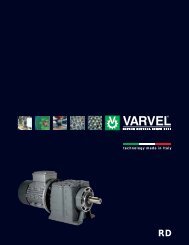
VARVELRPRIDUTTORI PER SISTEMI DI ALIMENTAZIONE A V<strong>IT</strong>E - SERIE RPGEARBOXES FOR FEEDING-SYSTEM SCREW CONVEYOR - SERIES RPGETRIEBE FÜR FUTTERUNGSANLAGER - BAUREIHE RPIl riduttore FRP71 è stato progettatoespressamente per l’azionamento deglialimentatori dei convogliatori a vite dei sistemid’alimentazione avicola a terra e fornisceun’ampia scelta di fissaggioall’alimentatore secondo i vari sistemiadottati. Il corpo monoblocco del riduttore èampiamente dimensionato per diminuire ledannose vibrazioni all’intero sistema ed ècostruito in lega d’alluminio pressofusaadatta a sopportare condizioni d’esercizioparticolarmente gravose. Gli ingranaggisono costruiti in acciaio legato, cementatoe temperato, sbarbati, dimensionati e verificatisecondo le norme ISO 6336 e DIN3990; i cuscinetti sono dimensionati peruna vita media di almeno 15.000 ore difunzionamento. Sedi linguette secondoDIN 6884. I riduttori sono spediti già riempiticon lubrificante sintetico a lunga durata(senza tappi), nella quantità adeguata perpermetterne l’installazione in tutte le posizionidi montaggio senza specificarle infase d’ordine.The gearbox FRP71 is expressly designedto be fitted on pick-up boots for feedingsystemscrew conveyors; the gearbox/bootfitting does not comply with any standardand a wide range of fittings is offered tomatch the customer’s need.The one-piece aluminium die-cast body isabundantly sized to avoid any harmful vibrationto the feeding system and to withstandheavy operations.Helical gears - made of alloy steel, casehardened,tempered and shaved - are designedand verified according to ISO 6336and DIN 3990.Bearings are calculated for at least 15,000running hour average lifetime. Keywaysaccording to DIN 6884.The gearboxes are delivered filled withsynthetic long-life oil (without plugs), in theappropriate quantity to install them in anymounting position without any prior specification.Das Getriebe FRP71 ist ausdrücklich entwickeltum auf Hebeeinrichtungen vonSchneckenförderern für Fütterungs-Systememontiert zu werden; die Getriebe/Antriebsmontage entspricht keinem sonstigenStandard und eine breite Reihe vonAnbaumöglichkeiten wird angeboten, umKundenwünsche zu erfüllen. Das einteiligeAluminium-Druckgussgehäuse ist ausreichenddimensioniert, um alle schädlichenVibrationen auf das Fütterungssystem zuvermeiden und um schweren Betriebsbedingungenzu widerstehen die Stirnräder,hergestellt aus gehärtetem Legierungsstahl,sind ausgelegt und gefertigt nachISO 6336 und DIN 3990. Die Lager sind füreine durchschnittliche Mindestlebensdauervon 15000 Betriebsstunden ausgelegt.Passfeder-Verbindungen entsprechen DIN6884. Die Getriebe werden mit synthetischemÖl Lebensdauer geschmiert geliefert(ohne Füllschrauben), um sie in allenEinbaulagen ohne Einschränkung einsetzenzu können.<strong>DE</strong>SIGNAZIONE <strong>DE</strong>SIGNATION BEZEICHNUNGF RP71 B5/160 3,94 IEC80-B14 905Albero Uscita - Output shaft - AbtriebswelleGrandezza IEC & Forma motore - IEC motor size & mounting - Baugröße Motor u. BauformRapporto di riduzione - Reduction ratio - UntersetzungsverhältnisFlangia uscita & diametro - Output flange & diameter - Abtriebsflansch u. DurchmesserF = Flangia entrata IEC - IEC metric input - Eingangsflansch IECM = Motoriduttore - Geared Motor - GetriebemotorGiri entrata 1400 min -1 - Input speed 1400 min -1 - Eingangsdrehzahl 1400 min -1P 1 i rn 2 M 2 M 2 max FS IEC P 1 i rn 2 M 2 M 2 max[kW][min -1 ] [Nm] [Nm][kW][min -1 ] [Nm] [Nm]FSIEC0,25 7,91 177 13,2 21 1,6 71B5 & 0,55 7,00 200 25,7 23 0,9 80B5 &7,00 200 11,7 23 2,0 71B14 5,70 246 21,0 25 1,2 80B145,70 246 9,5 25 2,6 5,07 276 18,6 28 1,55,07 276 8,5 28 3,3 4,73 296 17,4 29 1,74,73 296 7,9 29 3,7 3,94 355 14,5 30 2,13,94 355 6,6 30 4,6 3,20 437 11,8 33 2,83,20 437 5,3 33 6,2 2,52 556 9,3 35 3,82,52 556 4,2 35 8,3 0,75 5,70 246 28,6 25 0,9 80B5 &0,37 7,91 177 19,6 21 1,1 71B5 & 5,07 276 25,4 28 1,1 80B147,00 200 17,3 23 1,3 71B14 4,73 296 23,7 29 1,25,70 246 14,1 25 1,8 3,94 355 19,8 30 1,55,07 276 12,5 28 2,2 3,20 437 16,0 33 2,14,73 296 11,7 29 2,5 2,52 556 12,6 35 2,83,94 355 9,7 30 3,1 1,1 5,07 276 37,3 28 0,8 80B5 &3,20 437 7,9 33 4,2 4,73 296 34,8 29 0,8 80B142,52 556 6,2 35 5,6 3,94 355 29,0 30 1,03,20 437 23,5 33 1,02,52 556 18,5 35 1,9- 2 -
VARVELRPDIMENSIONI DI INGOMBROOVERALL DIMENSIONSABMESSUNGENFRP71 B5/1FRP71 SQFRP71 SQ/1* - Solo / Only / Nur IEC71-B14IEC 71 IEC 80B5 B14 B5 B14A 160 105 200 120B 130 85 165 100C E8 110 70 130 80D 10 7 10 7E 16.3 16.3 21.8 21.8F E8 14 14 19 19G 5 5 5 5- 3 -
VARVEL RPDIMENSIONI DI INGOMBROOVERALL DIMENSIONSABMESSUNGENFRP71 B5FRP71 B5/140FRP71 B5/160* - Solo / Only / Nur IEC71-B14IEC 71 IEC 80B5 B14 B5 B14A 160 105 200 120B 130 85 165 100C E8 110 70 130 80D 10 7 10 7E 16.3 16.3 21.8 21.8F E8 14 14 19 19G 5 5 5 5- 4 -
VARVEL RPDIMENSIONI DI INGOMBROOVERALL DIMENSIONSABMESSUNGENOpzioniOptions Ref. No. 1 Ref. No. 2 Ref. No. 3OptionenFRP71B5 - FRP71B5/1 - FRP71 B5/140 - FRP71B5/1N. CodiceCode No.Artikel Nr.Ref.No.A B C C’ D D’ E F G904 2 22 52 23 38 6.5 6.5 --- --- ---905 1 22 52 23 --- 8.5 --- --- --- ---906 3 19 40 --- --- --- --- 5 30 6908 1 22 52 20 --- 6.0 --- --- --- ---909 1 19.7 100 50 --- 6.0 --- --- --- ---913 1 22 52 26 --- 6.5 --- --- --- ---914 1 22 80 15 --- 8.5 --- --- --- ---915 1 19 77 38.5 --- 6.0 --- --- --- ---916 1 19 40 14 --- 8.5 --- --- --- ---917 1 20 85 45 --- 6.5 --- --- --- ---919 & 919.0<strong>01</strong>* 1 20 84 30 --- 6.0 --- --- --- ---923 1 19.7 100 50 --- 6.5 --- --- --- ---924 3 20 40 --- --- --- --- 5 30 6925 1 22 54 20 --- 8.0 --- --- --- ---926 1 20 40 20 --- 8.5 --- --- --- ---928 & 928.0<strong>01</strong>* 1 21 52 23 --- 6.0 --- --- --- ---929 2 20 84 30 40 7.0 7.0 --- --- ---930 & 930.0<strong>01</strong>* 1 21.6 80 15 --- 8.5 --- --- --- ---934 1 18.8 80 15 --- 8.5 --- --- --- ---935 & 935.0<strong>01</strong>* 1 20 52 23 --- 6.5 --- --- --- ---938 2 19.7 100 30 50 6.0 6.0 --- --- ---943.0<strong>01</strong>* 3 20 40 --- --- --- --- 5 30 6944.0<strong>01</strong>* 1 20 50 25 --- 6.0 --- --- --- ---FRP71SQ - FRP71SQ/1918 1 16 50 21 --- 7.0 --- --- --- ---921 1 19 57 23 --- 6.5 --- --- --- ---922 1 22 57 23 --- 8.5 --- --- --- ---932 1 19 57 23 --- 6.5 --- --- --- ---933 1 22 57 23 --- 8.5 --- --- --- ---936 1 21 57 23 --- 6.0 --- --- --- ---940 1 16 50 21 --- 6.5 --- --- --- ---Altre estremità d‘albero a richiesta - Other shaft ends on demand - Andere Ausgangswellen auf Anfrage9xx.0<strong>01</strong>* - FRP71 B5/140 & FRP71 B5/160 - Solo / Only / Nur- 5 -
VARVEL VSEstratto delle ISTRUZIONI D’USO E MANUTENZIONEAbstract of OPERATION AND MAINTENANCE INSTRUCTIONSZusammenfassung der BETRIEBS- UND WARTUNGSANWEISUNGENI riduttori e i variatori di velocità non ricadono nelcampo d’applicazione della Direttiva Macchine,art.1(2) e non possono essere messi in serviziofinché la macchina nella quale devono essereincorporati, sia stata dichiarata conforme all’art.4(2), all. II(B) delle Direttive Macchine 98/37/ CEe, solo per l’Italia, al DL 459/96.InstallazioneAccertarsi che il gruppo da installare abbia lecaratteristiche atte a svolgere la funzione richiestae che la posizione di montaggio sia coerentecon quanto ordinato. Tali caratteristiche sonodeducibili dalla targhetta d’identificazione appostasul riduttore. Eseguire la verifica della stabilitàdel montaggio affinché non avvengano vibrazionio sovraccarichi durante il funzionamento.FunzionamentoIl riduttore può essere collegato per rotazioneoraria o antioraria. Arrestare immediatamente ilriduttore in caso di funzionamento difettoso o dirumorosità anomala, rimuovere il difetto o ritornarel’apparecchio alla fabbrica per un adeguatocontrollo. Se la parte difettosa non è sostituita,anche altri elementi possono essere ulteriormentedanneggiati e originare una più scarsapossibilità di risalire alle cause.ManutenzioneSebbene i gruppi siano provati con funzionamentosenza carico prima della spedizione, èconsigliabile non usarli a carico massimo durantele prime 20-30 ore di funzionamento affinchéle parti interne possano adattarsi reciprocamente.I riduttori sono spediti già riempiti conolio sintetico a lunga durata e, se occorre sostituireo rabboccare il lubrificante, non mescolareoli a base sintetica con oli a base minerale.MovimentazioneIn caso di sollevamenti con paranco, utilizzareposizioni di aggancio sulla struttura della carcassa,golfari ove esistenti, fori dei piedi o sulleflange, evitando tutte le parti mobili.VerniciaturaQualora il gruppo subisca una verniciatura successiva,è necessario proteggere accuratamentegli anelli di tenuta, i piani di accoppiamentoe gli alberi sporgenti.Conservazione prolungata a magazzinoPer permanenze maggiori di tre mesi, è consigliatal’applicazione di antiossidanti su alberiesterni e piani lavorati, e di grasso protettivo suilabbri dei paraolio.Gestione Ambientale del prodottoIn conformità alla Certificazione Ambientale ISO140<strong>01</strong>, sono suggerite le seguenti indicazioniper lo smaltimento del nostro prodotto:- i componenti del gruppo che vengono rottamatidebbono essere consegnati a centri di raccolta autorizzatiper i materiali metallici;gli oli ed i lubrificanti raccolti dal gruppo devonoessere smaltiti consegnandoli ai Consorzi Oliesausti;- gli imballi a corredo dei gruppi (pallet, cartone,carta, plastica, ecc.) vanno avviati per quantopiù possibile al recupero/riciclo, consegnandoli aditte autorizzate per le singole classi di rifiuto.Direttiva ATEXI riduttori VARVEL-ATEX, fornibili su richiesta,sono progettati e costruiti in accordo alla Direttiva94/9/CE “Atex” e sono pertanto idonei allainstallazione in atmosfere potenzialmente esplosive:• Zone di Gruppo II,• Categoria 2 (o 3),• Pericolo di esplosione in presenza di Gas(Zona 1 o 2),• Pericolo di esplosione in presenza di Polvericombustibili (Zona 21 o 22).Variable speed and reduction gearboxes are notpart of the field of application of the MachineryDirective, art.1(2), and they must not be put intoservice until the machinery into which they areto be incorporated, has been declared in conformitywith the provision of art.4(2), annex II(B) ofMachinery Directives 98/37/CE and for Italyonly, of DL 459/96.InstallationCheck if the unit to be installed is properly selectedto perform the required function and thatits mounting position complies with the order.The nameplate reports such information.Check mounting stability to run the unit withoutvibrations or overloads.RunningThe unit may be connected for clockwise orcounter-clockwise rotation.The unit must be stopped as soon as defectiverunning or unexpected noise occur, remove thefaulty part or return the unit to the factory forchecking.If the faulty part is not replaced, other parts canalso be affected, causing more severe damageand making the identification of initial causemore difficult.MaintenanceAlthough the units are no-load run tested in thefactory before despatch, it is recommended notto run them at maximum load for the first 20-30running hours to allow the proper running in.The gearboxes are delivered already filled withlong-life synthetic oil and, in case of replacementor topping, do not mix with mineral lubricants.HandlingWhen hoisting, use relevant housing locations oreyebolts if provided, or foot or flange holesNever hoist on any moving part.PaintingCarefully protect oil seals, coupling faces andshafts when units are re-painted.Long-term storageFor storages longer than 3 months, apply antioxidantsonto shafts and machined surfaces,and protective grease on oil seal lips.Product’s Environmental ManagementIn conformity with Environmental CertificationISO 140<strong>01</strong>, we recommend the following to disposeof our products:- scraped components of the units to deliver to authorizedcentres for metal object collection;oils and lubricants drained from the units to deliverto Exhausted Oil Unions;- packages (pallets, carton boxes, paper, plastic,etc.) to lead into regeneration/recycling circuitsas far as possible, by delivering separate wasteclasses to authorized companies.Directive ATEXThe gearboxes Series VARVEL-ATEX, deliveredon demand, are designed and manufacturedaccording to Directive 94/9/CE “Atex” andtherefore, they are qualified for installation inpotentially explosive atmospheres of:• Zones of Group II,• Category 2 (or 3),• Explosion hazard with gas presence (Zone1 or 2),• Explosion hazard with combustible dustpresence (Zone 21 or 22).<strong>Varvel</strong>-Getriebe und Variatoren fallen nicht unterden Geltungsbereich der Maschinenrichtlinien,Artikel 1 (2): Sie dürfen jedoch nicht in Betriebgesetzt werden, bevor sich nicht Maschinen, indie sie eingebaut werden, mit Artikel 4 (2), AnhangII (B) der Maschinenrichtlinien 98/37/CE,und (nur für Italien) DL 459/96, in Übereinstimmungbefinden.AufstellungVor der Aufstellung ist zu prüfen, dass die Antriebseinheitin bezug auf die Betriebsbedingungenrichtig ausgewählt wurde und die Einbaulagemit der Bestellung übereinstimmt. Angaben hierübersind auf dem Typenschild zu finden. DieStützkonstruktion für die Getriebe ist so stabilauszuführen, dass keine Schwingungen oderÜberlastungen auftreten, eventuell sind elastischeKupplungen oder Drehmomentbegrenzterzu verwenden.InbetriebnahmeDie Antriebseinheit kann in beiden Drehrichtungeneingesetzt werden. Die Einheit müsst sofortangehalten werden, wenn ein unzulässiger Laufoder unerwartete Geräusche auftreten.Das fehlerhafte Teil ist zu ersetzen oder die Einheitist zur Überprüfung einzuschicken. Falls dasfehlerhafte Teil nicht ersetzt wird, kann dies zuweiteren Schäden an anderen Bauteilen führen,was eine Feststellung der Ursachen sehr schwierigmachen kann.WartungObwohl die Einheiten vor der Auslieferung imLeerlauf getestet wurden, ist es ratsam sie in denersten 20-30 Stunden nicht mit vorlast zu betreiben,um ein einwandfreies Einlaufen zu gewährleisten.Die Einheiten werden entsprechend denAngaben auf dem Typenschild mit synthetischemSchmierstoff Lebensdauer geschmiertausgeliefert. Bei einem eventuellen Ölwechseloder Nachfüllen darf der Schmierstoff nicht mitMineralöl vermischt werden.Handhabung und TransportBeim Heben und Transport ist auf standsichereLage und sorgfältige Befestigung geeigneter Hebevorrichtungenzu achten. Bewegliche Teiledürfen nicht zum Anheben benutzt werden.AnstrichBeim Erneuern oder dem zusätzlichen Aufbringeneines Anstriches sind die Dichtungen,Kupplungssitze und Wellen sorgfältig zu schützen.LangzeitlagerungDie Einlagerung der Einheiten muss trocken undstaubfrei erfolgen. Bei einer Einlagerungszeitüber 3 Monate sind bearbeitete Flächen undWellen mit Rostschutzmitteln zu besprühen,Dichtlippen sind mit Fett zu schützen.EntsorgungIn Übereinstimmung mit ISO 140<strong>01</strong> weisen wirdarauf hin, im Falle des Verschrottens die einzelnenMetallteile getrennt zu behandeln undSchmiermittel bei den befugten Stellen zu entsorgen.Verpackungen sollten soweit wie möglich wiederverwendet werden.ATEX RichtlinienDie Getriebe der Serie VARVEL-ATEX, ausschließlichauf Anfrage geliefert, sind entsprechendden Atex-Richtlinien 94/9/EG konstruiertund hergestellt und somit zugelassen für die Installationin potentiell zündfähigen Atmosphäre:• Gefahrenbereiche der Gruppe II,• Kategorie 2 (oder 3),• Explosiongefärdeter Bereich mit Gase (Gefahrenbereiche1 oder 2),• Explosiongefärdeter Bereich mit zündfähigenStäube (Gefahrenbereiche 21 oder22).- 6 -