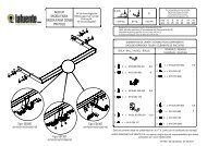
Einbauanleitung - Home - AHK - RATGEBER
Einbauanleitung - Home - AHK - RATGEBER
Einbauanleitung - Home - AHK - RATGEBER
- No tags were found...

You also want an ePaper? Increase the reach of your titles
YUMPU automatically turns print PDFs into web optimized ePapers that Google loves.
<strong>Einbauanleitung</strong>:Elektroanlage für AnhängevorrichtungWestfaliaAudi305 269 300 107 – – Audi A6: Limousine, 05/04 -305 269 300 113 – – Audi A6: Limousine, 05/04 -305 272 300 107 – – Audi A6: Avant 12/04 - , allroad quattro 02/06 -305 272 300 113 – – Audi A6: Avant 12/04 - , allroad quattro 02/06 -5342116 7 8542 316 7 8Audi A6 305 272 391 101 - 004 - 44/07 3
<strong>Einbauanleitung</strong>:Elektroanlage für Anhängevorrichtung<strong>Einbauanleitung</strong>:Elektroanlage für AnhängevorrichtungWichtige HinweiseVor Arbeitsbeginn die <strong>Einbauanleitung</strong> lesen.Der Elektroeinbausatz darf nur von qualifiziertem Fachpersonal eingebaut werden.Vorsicht - Batterie abklemmen!Beschädigung der KFZ-Elektronik, elektronisch gespeicherte Daten können verlorengehen.Vor Arbeitsbeginn den Fehlerspeicher auslesen.HinweisBei der Montage auf folgende Punkte besonders achten:• Leitungen dürfen weder eingeklemmt noch beschädigt sein.• Alle Dichtungselemente ordnungsgemäß anbringen.• Die Steckdosendichtung muss auf dem Isolierschlauch positioniert werden und nicht aufden Einzeladern.• Leitungen so verlegen, dass diese weder am Fahrzeug scheuern noch abknicken.• Leitungen nicht in unmittelbarer Nähe der Abgasanlage verlegen.• Steuergeräte so anbringen, dass keine Feuchtigkeit eindringen kann. DerKabelanschluss soll immer nach unten zeigen.Die zusätzliche Kontroll-Leuchte (C2) zur Kontrolle der Fahrtrichtungsanzeiger am Anhänger istbereits fahrzeugseitig vorhanden und entsprechend vorkonfektioniert.Bei Anhängerbetrieb wird die Nebelschlussleuchte des Zugfahrzeugs abgeschaltet.Bei Anhängern ohne Nebelschlussleuchte muss diese nachgerüstet werden.Ein Steckdosenadapter darf nur im Anhängerbetrieb genutzt werden. Nach dem Anhängerbetriebden Steckdosenadapter entfernen.Die Prüfung der Anhängerfunktionen mit einem Anhänger oder einem Prüfgerät mitBelastungswiderständen durchführen.Technische Änderungen vorbehalten!4 305 272 391 101 - 004 - 44/07 Audi A6
<strong>Einbauanleitung</strong>:Elektroanlage für AnhängevorrichtungElektrosatz einbauen1. Batterie abklemmen.2. Folgende Abdeckungen und Verkleidungen ggf. entfernen:• Im Kofferraum- Abdeckung des Kofferraumbodens- Ladekantenabdeckung- Verkleidung der rechten Seite des Kofferraumes3. Die fahrzeugseitige 40 mm Lochabdeckung links neben der Mitte im Heckabschlussblech(Abb. 1/6) entfernen.4. Das Leitungsende mit dem 16-poligen Stecker von außen durch die Kabel-Durchführung zumGeräteträger (Abb. 1/4) verlegen.5. Die Gummitülle in die Kabel-Durchführung (Abb. 1/6) einsetzen.6. Das Steckdosenende des Leitungssatzes zum Steckdosenhalteblech (Abb. 1/7) verlegen.7. Den Leitungssatz evtl. mit einem Kabelbinder an der Anhängevorrichtung befestigen.Steckdose montieren8. Den Kontakteinsatz in das Steckdosengehäuse eindrücken und die Gummidichtung an dieSteckdose heranschieben.9. Die Steckdose mit den beiliegenden Schrauben am Steckdosenhalteblech (Abb. 1/7)festschrauben.Anhängeranschlussgerät anschließenHinweis (nur für Limousine)Falls der Geräteträger 4F0 907 179 für das Anhängersteuergerät nicht im Fahrzeugvorhanden ist, muss dieser mit einer Duoschraube (N907 717 01) und einer Kombimutter(N902 867 03) über VW Kassel bestellt werden.10. Das Anhängersteuergerät in den Geräteträger (Abb. 1/1) einstecken und verrasten.11. Das Steckergehäuse 16-fach in den vorgesehenen Steckplatz des Anhängersteuergerätesstecken und verrasten.12. Das Steckergehäuse 12-fach des 14-adrigen Leitungssatzes in den vorgesehenen Steckplatzdes Anhängersteuergerätes stecken und verrasten.Audi A6 305 272 391 101 - 004 - 44/07 5
<strong>Einbauanleitung</strong>:Elektroanlage für Anhängevorrichtung13. Den blauen 32-poligen Stecker vom Komfortsteuergerät (Abb. 1/5) abziehen undVerriegelung öffnen. Folgende Leitungen entriegeln und in das am Leitungssatz befindlichen3-polige schwarze Buchsengehäuse einsetzen:- Leitung orange/braun aus Kammer 1 in Kammer 1.- Leitung orange/grün aus Kammer 17 in Kammer 3.14. Aus dem 14-adrigen Leitungssatz die Einzelleitungen orange/braun und orange/grünfarbenrichtig in die freigewordenen Kammern 1 und 17 des 32-poligen Steckers einsetzen.15. Folgende Leitungen entriegeln und in das am Leitungssatz befindlichen 3-polige weißeBuchsengehäuse einsetzen:- Leitung schwarz/weiß (weiß/rot bei Avant RHD) aus Kammer 19 in Kammer 3.- Leitung schwarz/rot aus Kammer 20 in Kammer 2.- Leitung schwarz aus Kammer 21 in Kammer 1.16. Aus dem 14-adrigen Leitungssatz die Einzelleitungen schwarz/weiß, schwarz/rot und schwarzfarbenrichtig in die freigewordenen Kammern 19, 20 und 21 des 32-poligen Steckerseinsetzen.17. Verriegelungen schließen und Stecker wieder auf das Komfortsteuergerät aufstecken.18. Die nun offenen 3-poligen Gehäuse farbenrichtig zusammenstecken.19. Die braunen Leitungen mit den Ringösen an den fahrzeugseitigen Massepunkt (Abb. 1/2)hinten rechts anschließen.20. Am rechten braunen Sicherungsträger (Abb. 1/3) hintere Abdeckung entfernen und violetteVerriegelung öffnen. Folgende Leitungen in die jeweilige Sicherungskammer einsetzen (beiBedarf vorher Geräteträger demontieren):- Leitung rot in Kammer 10.- Leitung rot/schwarz in Kammer 11.- Leitung rot/blau in Kammer 12.HinweisFalls der rechte, braune Sicherungsträger im Fahrzeug nicht vorhanden ist, muss dieserunter 4F0 055 307 (>>MY06), 4F0 055 307 A (MY07>>) über Votex bestellt werden.21. Violette Verriegelung am Sicherungsträger schließen.22. In Sicherungsplatz 10, 11 und 12 beiliegende 15-A-Sicherungen einsetzen.23. Nur für 13-polige Anhängersteckdose:Über den weißen 3-poligen Stecker für die Dauerplus-Vorbereitung (Abb. 1/8) können dieFunktionen "Ladeleitung" und "Masse für Ladeleitung" nachgerüstet werden (im Fachhandelunter Bestellnummer 300 025 300 113 zu beziehen).6 305 272 391 101 - 004 - 44/07 Audi A6
<strong>Einbauanleitung</strong>:Elektroanlage für AnhängevorrichtungFunktion prüfen24. Fahrzeugbatterie wieder anschließen.25. Passen Sie die Codierung des Fahrzeuges bei folgenden SG über geführte Fehlersuche an,in dem sie auf "Anhängerkupplung verbaut" umstellen:- 01 Motorelektrik (motorabhängig, in geführter Fehlersuche ersichtlich)- 13 Distanzregelung ACC- 19 Diagnoseinterface für Datenbus- 34 Niveauregulierung- 45 Bremsenelektronik ESP- 76 Einparkhilfe26. Codieren sie über geführte Fehlersuche das Anhänger-Anschlussgerät auf "ohneSchwenkfunktion".- \Karosserie\Elektrische Anlage\Anhängerfunktion\J345 Steuergerät fürAnhängererkennung, Funktionen- J345 - Codierung - "ohne Schwenkfunktion".27. Die Anhängerfunktionen mit einem geeigneten Prüfgerät (mit Belastungswiderständen) odermit einem Anhänger prüfen.28. Alle Leitungen mit Kabelbindern befestigen.29. Alle ausgebauten Teile wieder einbauen.Audi A6 305 272 391 101 - 004 - 44/07 7
Instructions de montage:Installation électrique pour dispositif d’attelageInstructions de montage:Installation électrique pour dispositif d’attelageRemarques importantesAvant de commencer l'intervention, lire les instructions d'installation.L'installation du module électronique ne doit être réalisée que par des techniciens qualifiés.Attention - débrancher la batterie !Endommagement de l'électronique du véhicule, les données enregistréesélectroniquement peuvent être perdues.Extraire la mémoire des erreurs avant de commencer l'intervention.RemarqueObserver avec attention les points suivants lors du montage :• Les fils ne doivent pas être endommagés ou pincés.• Installer tous les joints dans l'ordre établi.• Le joint de la prise de courant doit être placé sur la gaine isolante et non sur unconducteur unique.• Disposer les fils de façon à ce qu'ils ne puissent pas frotter sur le véhicule ou rompre.• Ne pas placer les fils à proximité immédiate du système d'échappement.• Brancher le dispositif de commande de manière à ce que l’humidité ne puisse pass’infiltrer. Le raccord de câbles doit toujours être dirigé vers le bas.Les feux de contrôle supplémentaires (C2) servant au contrôle de l'afficheur de la direction sur ledispositif d'attelage sont déjà présents côté véhicule et sont pré-configurés de manière adéquate.Lors de l'utilisation de l'attelage, les feux anti-brouillard arrière du véhicule tractant sont mis àl'arrêt.Pour les attelages sans feux anti-brouillard arrière, il faut en installer.Un adaptateur de prise femelle ne doit être utilisé que pour le fonctionnement de l'attelage.Retirer cet adaptateur une fois que l'attelage n'est plus utilisé.Tester le fonctionnement de l'attelage avec un attelage ou un dispositif de contrôle avec unerésistance fixe.Sous réserve de modifications techniques !8 305 272 391 101 - 004 - 44/07 Audi A6
Instructions de montage:Installation électrique pour dispositif d’attelageInstallation du module électronique1. Débrancher la borne négative de la batterie.2. Le cas échéant, retirer les revêtements et garnitures suivants :• Dans le coffre- Revêtement du fond du coffre à bagages- Revêtement de l’arête de chargement- Revêtement du côté droit du coffre à bagages3. Retirer le cache-trou de 40 mm côté véhicule à gauche près du milieu de la plaque deserrage arrière (Fig. 1/6).4. Faire passer l’extrémité du fil avec la fiche à 16 pôles depuis l’extérieur par le passage decâble jusqu’au support du dispositif (Fig. 1/4).5. Insérer le passe-fil en caoutchouc dans le passage du câble (Fig. 1/6).6. Placer l’extrémité de la prise femelle de l’ensemble de fils sur la tôle de retenue de la prise(Fig. 1/7).7. Fixer éventuellement l'ensemble de fils avec un attache-câbles sur le dispositif d'attelage.Montage de la prise8. Appuyer le contact dans le bâti de la prise et faire glisser vers le bas le joint en caoutchoucsur la prise.9. Fixer la prise sur la plaque de retenue de la prise (Fig. 1/7) avec les vis fournies.Brancher le dispositif de connexion du dispositif d’attelageRemarqueSi le support de dispositif 4F0 907 179 pour la commande du dispositif d'attelage n'est pasdisponible dans le véhicule, il doit être commandé auprès de VW Kassel avec une vis Duo(N907 717 01) et un écrou combiné (N902 867 03).10. Placer et insérer le dispositif de commande du dispositif d'attelage dans le support dudispositif (Fig. 1/1).11. Placer et insérer le boîtier de connexion (16) dans l’emplacement du module de commandedu dispositif d’attelage prévu à cet effet.12. Placer et insérer le boîtier de connexion (12) de l’ensemble à 14 fils dans l’emplacement dumodule de commande du dispositif d’attelage prévu à cet effet.Audi A6 305 272 391 101 - 004 - 44/07 9
Instructions de montage:Installation électrique pour dispositif d’attelage13. Retirer la fiche bleue à 32 pôles du dispositif de commande Confort (Fig. 1/5) et ouvrir lesystème de verrouillage. Déverrouiller les fils suivants et les insérer dans le bâti à douillesnoir 3 pôles se trouvant sur l'ensemble de fils :- Fil orange/marron du logement 1 au logement 1.- Fil orange/vert du logement 17 au logement 3.14. Insérer les fils uniques orange/marron et orange/vert de l'ensemble 14 fils dans les logements1 et 17 ainsi libérés de la fiche à 32 pôles en respectant les couleurs.15. Déverrouiller les fils suivants et les insérer dans le bâti à douilles blanc 3 pôles se trouvantsur l'ensemble de fils :- Fil noir/blanc (Avant RHD = blanc/rouge) du logement 19 au logement 3.- Fil noir/rouge du logement 20 au logement 2.- Fil noir du logement 21 au logement 1.16. Insérer les fils uniques noir/blanc, noir/rouge et noir de l'ensemble 14 fils dans les logements19, 20 et 21 ainsi libérés de la fiche à 32 pôles en respectant les couleurs.17. Fermer le système de verrouillage et mettre de nouveau le connecteur en place sur ledispositif de commande Confort.18. Relier ensemble les boîtiers 3 pôle maintenant ouverts en respectant les couleurs.19. Raccorder les fils marron avec les anneaux sur le point matériel du côté du véhicule (Fig. 1/2)dans la partie arrière droite.20. Sur le porte-fusibles droit (Fig. 1/3), retirer le revêtement arrière et ouvrir le système deverrouillage violet. Insérer les fils suivants dans les logements pour fusible correspondants (sinécessaire, démonter auparavant le support du dispositif) :- Fil rouge dans l’emplacement 10.- Fil rouge/noir dans l’emplacement 11.- Fil rouge/bleu dans l’emplacement 12.RemarqueSi le porte-fusibles brun de droite est absent du véhicule, il est nécessaire de le commandersous 4F0 055 307 (>>MY06), 4F0 055 307 A (MY07>>) par Votex.21. Fermer le système de verrouillage violet sur le porte-fusibles.22. Insérer dans les emplacements pour fusible 10, 11 et 12 les fusibles 15 A fournis.23. Uniquement pour la prise de courant de l'attelage à 13 pôles:Les fonctions "Fil de charge" et "Masse pour le fil de charge" peuvent être installées via lafiche 3 pôles blanche pour la préparation du plus permanent (disponible dans la commercesous le numéro de commande 300 025 300 113).10 305 272 391 101 - 004 - 44/07 Audi A6
Installation instructions:Electrical system for towing hitchInstallation instructions:Electrical system for towing hitchImportant notesRead the installation manual prior to starting work.The electrical kit should only be installed by qualified personnel.Caution – Disconnect the battery!Danger of damage to the vehicle’s electronic system. Data which are storedelectronically may get lost.Read out the fault storage prior to starting work.NoteDuring installation special attention has to be paid to the following points:• Cables must not be pinched or damaged.• All sealing elements have to be installed properly.• The socket gasket has to be positioned on the insulating sleeve and not on the individualwires.• Lay the cables such that they do not rub on the vehicle and are not bent.• Do not lay any cables near the exhaust system.• Install the controller such that it is protected against the ingress of humidity. The cableconnection should always face downward.The additional indicator light (C2) for monitoring the direction indicators on the trailer is alreadyinstalled in the vehicle and prepared accordingly.When a trailer is used, the rear fog lamp of the traction vehicle is deactivated.In the case of trailers without rear fog lamp, a rear fog lamp has to be retrofitted.A socket adapter may only be used in conjunction with a trailer. When the trailer is no longerused, remove the socket adapter.Correct trailer operation has to be checked using a trailer or a test instrument with load resistors.Subject to technical alterations!12 305 272 391 101 - 004 - 44/07 Audi A6
Installation instructions:Electrical system for towing hitchInstalling the electrical kit1. Disconnect the negative battery terminal.2. If necessary, remove the following coverings and panels:• In the luggage trunk- Covering of luggage trunk bottom- Loading edge covering- Covering of the right side of the luggage trunk3. Remove the vehicle’s 40 mm hole cover on the left of the centre in the rear end plate(Fig. 1/6).4. Lay the cable end with the 16-pin plug from the outside through the cable leadthrough to thecomponent carrier (Fig. 1/4).5. Insert the rubber grommet into the cable leadthrough (Fig. 1/6).6. Lay the socket end of the cable set to the socket holder plate (Fig. 1/7).7. Attach the cable set to the towing hitch with a cable tie if necessary.Installing the socket8. Press the contact insert into the socket housing and push the rubber grommet towards thesocket.9. Screw the socket onto the socket holding plate (Fig. 1/7) using the supplied screws.Connecting the trailer connection unitNoteIf the component carrier 4F0 907 179 for the trailer control unit does not exist in the vehicle,the component carrier must be ordered via VW Kassel with a twin bolt (N907 717 01) and acombination nut (N902 867 03).10. Insert the trailer control unit into the component carrier (Fig. 1/1) and lock it in place.11. Insert the 16-fold connector housing into the intended slot of the trailer control unit and lock itinto place.12. Insert the 12-fold connector housing of the 14-core cable set into the intended slot of thetrailer control unit and lock it into place.Audi A6 305 272 391 101 - 004 - 44/07 13
Installation instructions:Electrical system for towing hitch13. Disconnect the blue 32-pin connector from the Comfort Control Unit (Fig. 1/5) and open thelatch. Unlock the following wires and insert them into the black 3-pin socket housing providedon the cable set:- The orange/brown wire from compartment 1 into compartment 1.- The orange/green wire from compartment 17 into compartment 3.14. Insert the individual orange/brown and orange/green wires of the 14-core cable set into thenow free compartments 1 and 17 of the 32-pin plug as indicated by the colours.15. Unlock the following wires and insert them into the white 3-pin socket housing provided on thecable set:- Black/white (Avant RHD = white/red) wire from compartment 19 to compartment 3.- The black/red wire from compartment 20 into compartment 2.- Black wire from compartment 21 to compartment 1.16. Insert the individual black/white, black/red and black wires of the 14-core cable set into thenow free compartments 19, 20 and 21 of the 32-pin plug as indicated by the colours.17. Close the latch and re-insert the connector into the Comfort Control Unit.18. Fit the now open 3-pin housings together as indicated by the colours.19. Connect the brown wires with the eyelets to the vehicle’s ground point (Fig. 1/2) at the rearright.20. Remove the rear cover on the right fuse carrier (Fig. 1/3) and open the violet latch. Insert thefollowing wires into the respective fuse chamber (remove component carrier before ifrequired):- The red wire into compartment 10.- The red/black wire into compartment 11.- The red/blue wire into compartment 12.NoteIf there is no brown fuse box on the right in the vehicle, one must be ordered from Votex,number 4F0 055 307 (>>MY06), 4F0 055 307 A (MY07>>).21. Close violet latch on the fuse carrier.22. Insert the supplied 15 A fuses into fuse compartments 10, 11 and 12.23. For 13-pin trailer socket only:Using the white 3-pin connector for the constant plus extension kit, the functions "charginglead" and "ground for charging lead" can be retrofitted (available in specialised shops underthe order number 300 025 300 113).14 305 272 391 101 - 004 - 44/07 Audi A6
Installation instructions:Electrical system for towing hitchChecking correct operation24. Reconnect the ground of the vehicle’s battery.25. Match the vehicle code in the following control units via selected diagnostics by coding“Anhängerkupplung verbaut 1D2" (towing hitch installed 1D2):- 01 Engine control unit- 13 Distance control ACC- 19 Diagnosis interface for data bus- 34 Level control- 45 Brake electronics ESP- 76 Park distance control26. Using the selected diagnostics code the trailer connection unit to "ohne Schwenkfunktion"(without hinge function)- \car body\electrical system\trailer function\J345 control unit for trailer detection, functions- J 345 coding - " ohne Schwenkfunktion" (without hinge function)27. Check the trailer function with the help of a suitable test instrument (with load resistors) orwith the help of a trailer.28. Secure all cables using cable ties.29. Refit any parts removed for installation.Audi A6 305 272 391 101 - 004 - 44/07 15
Istruzioni per l'installazione:Impianto elettrico per il gancio di trainoIstruzioni per l'installazione:Impianto elettrico per il gancio di trainoNote importantiPrima di iniziare i lavori, leggere le istruzioni di montaggio.Il kit elettrico deve essere montato solo da personale qualificato.Attenzione - Staccare la batteria!Danni all'elettronica del veicolo, i dati memorizzati possono essere persi.Prima di iniziare consultare la memoria degli errori.NotaDurante il montaggio prestare molta attenzione a quanto segue:I cavi non devono essere bloccati o danneggiati.Posizionare tutte le guarnizioni a regola d'arte.La guarnizione della presa deve essere posizionata sulla guaina isolante e non sui singoli fili.Posare i cablaggi in modo tale, che non sfreghino contro il veicolo e non risultino piegati.Non posare i cablaggi nelle immediate vicinanze dell'impianto gas di scarico.Montare le centraline in modo tale che non possa entrare umidità. Il collegamento del cavodeve essere sempre rivolto verso il basso.La lampada (C2) di controllo degli indicatori di direzione del rimorchio è già presente epreconfigurata sul veicolo.In caso di funzionamento con rimorchio viene spenta la luce retronebbia del veicolo.In caso di rimorchi non corredati di luce retronebbia, questa dovrà essere prevista.La presa adattatore può essere impiegata solo in presenza del rimorchio. Staccando il rimorchiotogliere anche la presa adattatore.Verificare le funzioni con il rimorchio stesso oppure un dispositivo di misurazione con resistenzedi carico.Con riserva di modifiche tecniche!16 305 272 391 101 - 004 - 44/07 Audi A6
Istruzioni per l'installazione:Impianto elettrico per il gancio di trainoMontaggio del kit elettrico1. Staccare il morsetto negativo dalla batteria.2. Togliere eventualmente le seguenti coperture e rivestimenti:• Nel bagagliaio- copertura del pianale di carico- copertura del bordo di carico- rivestimento del lato destro del bagagliaio3. Rimuovere la copertura del foro da 40 mm a sinistra, in prossimità del centro, della lamieraposteriore del bagagliaio (fig. 1/6).4. Far passare dall'esterno il terminale del cavo con lo spinotto a 16 poli attraverso il passacavie portarlo fino al porta-apparecchi (fig. 1/4).5. Infilare la bussola di gomma nel foro di passaggio cavi (fig. 1/6).6. Portare l'estremità della presa del fascio cavi alla lamiera portapresa (fig. 1/7).7. Se necessario, fissare il fascio di cavi con una fascetta sul gancio di traino.Montaggio della presa8. Inserire il contatto ad innesto nel corpo della presa e avvicinare la guarnizione di gomma allapresa.9. Fissare la presa al suo supporto (fig. 1/7) mediante le viti fornite in dotazione.Allacciamento del modulo di collegamento rimorchioNotaSe il porta-apparecchi 4F0 907 179 per la centralina di comando rimorchio non è presentenel veicolo, deve essere ordinato alla VW Kassel insieme ad una vite doppia (N907 717 01)ed un dado combinato (N902 867 03).10. Inserire e bloccare la centralina di comando rimorchio nel porta-apparecchi (fig. 1/1).11. Inserire e bloccare in posizione il corpo della spina a 16 poli nel relativo connettore dellacentralina di comando rimorchio.12. Inserire e bloccare in posizione il corpo della spina a 12 poli del fascio di cavi a 14 conduttorinel relativo connettore della centralina di comando rimorchio.Audi A6 305 272 391 101 - 004 - 44/07 17
Istruzioni per l'installazione:Impianto elettrico per il gancio di traino13. Estrarre lo spinotto blu a 32 poli dalla centralina di comando comfort (fig. 1/5) ed aprire ilbloccaggio. Sbloccare i seguenti cavi ed applicarli nel corpo bussola nero a 3 poli situato sulfascio di cavi:- conduttore arancione/marrone dalla camera 1 alla camera 1;- conduttore arancione/verde dalla camera 17 alla camera 3.14. Inserire i conduttori arancione/marrone ed arancione/verde del fascio di cavi a 14 conduttorinelle camere 1 e 17 ora libere dello spinotto a 32 poli verificando la correttezza dei colori.15. Sbloccare i seguenti cavi ed applicarli nel corpo bussola bianco a 3 poli situato sul fascio dicavi:- conduttore nero/bianco (Avant RHD = bianco/rosso) dalla camera 19 alla camera 3.- conduttore nero/rosso dalla camera 20 alla camera 2.- conduttore nero dalla camera 21 alla camera 1.16. Inserire i conduttori nero/bianco, nero/rosso e nero del fascio di cavi a 14 conduttori nellecamere 19, 20 e 21 ora libere dello spinotto a 32 poli verificando la correttezza dei colori.17. Chiudere i bloccaggi e ricollegare gli spinotti alla centralina di comando comfort.18. Collegare insieme i corpi a 3 poli ora aperte verificando la correttezza dei colori.19. Collegare i cavi marroni corredati degli occhielli alla massa del veicolo (fig. 1/2) sul latoposteriore destro.20. Togliere il coperchio posteriore del portafusibili destro (fig. 1/3) ed aprire il bloccaggio viola.Applicare i seguenti cavi nelle rispettive camere fusibili (se necessario, prima smontare ilporta-apparecchi):- conduttore rosso nella camera 10.- conduttore rosso/nero nella camera 11.- conduttore rosso/blu nella camera 12.AvvertenzaNel caso in cui il portafusibili destro color marrone non sia presente nel veicolo, deve essereordinato presso Votex con il codice 4F0 055 307 (>>MY06), 4F0 055 307 A (MY07>>).21. Chiudere il bloccaggio viola sul portafusibili.22. Applicare i fusibili da 15 A forniti in dotazione nelle posizioni 10, 11 e 12.23. Solo per presa del rimorchio a 13 poli:Mediante lo spinotto bianco a 13 poli per la preparazione del positivo permanente si possonorealizzare a posteriori le funzioni "Cavo di carica" e "Massa per il cavo di carica" (acquisto darivenditori specializzati con codice articolo 300 025 300 113).18 305 272 391 101 - 004 - 44/07 Audi A6
Istruzioni per l'installazione:Impianto elettrico per il gancio di trainoVerifica del funzionamento24. Ricollegare la massa della batteria del veicolo.25. Adattare la codifica del veicolo per i seguenti SG mediante ricerca guasti eseguita, passandoa "gancio rimorchio montato 1D2":- 01 impianto elettrico del motore (a seconda del motore, visibile dopo aver eseguito laricerca guasti)- 13 regolazione della distanza ACC- 19 interfaccia di diagnosi per bus dati- 34 regolazione del livello- 45 elettronica dei freni ESP- 76 sensore di parcheggio26. Codificare mediante ricerca guasti eseguita lo strumento di aggancio rimorchio su "senzafunzione di ribaltamento".- \Carrozzeria\impianto elettrico\funzionamento rimorchio\centralina J345 perriconoscimento rimorchio, funzioni- Codifica J 345 - " senza funzione di ribaltamento"27. Verificare il funzionamento del rimorchio mediante dispositivo idoneo (con resistenze dicarico) o collegando il rimorchio stesso.28. Fissare tutti i cavi con fascette stringicavo.29. Rimontare tutte le parti smontate precedentemente.Audi A6 305 272 391 101 - 004 - 44/07 19
Inbouwinstructie:Elektrische installatie voor trekhaakInbouwinstructie:Elektrische installatie voor trekhaakBelangrijke opmerkingenLees voor begin van de werkzaamheden de montagehandleiding door.De elektrische montageset mag uitsluitend worden gemonteerd door gekwalificeerd personeel.Pas op – accu afklemmen!Beschadiging van de voertuigelektronica, elektronisch bewaarde gegevens kunnenverloren gaan.Voor begin van de werkzaamheden foutgeheugen uitlezen.Pas opLet bij de montage vooral op de volgende punten:• Leidingen mogen noch worden ingeklemd noch beschadigd.• Alle dichtingselementen goed bevestigen.• De stopcontactpakking moet op de isolatieslang worden gepositioneerd en niet op deenkelvoudige aders.• Leidingen zo leggen dat deze noch aan het voertuig wrijven noch knikken.• Leidingen niet in de directe nabijheid van de uitlaatinstallatie leggen.• Regeleenheden zodanig monteren dat geen vochtigheid binnen kan dringen. Dekabelaansluiting moet altijd naar beneden wijzen.De aanvullende controlelamp (C2) voor de controle van de richtingaanwijzer op de aanhanger isreeds aan het voertuig aanwezig en overeenkomstig voorgeconfectioneerd.Bij rijden met een aanhanger wordt de mistachterlamp van het trekvoertuig uitgeschakeld.Bij aanhangers zonder mistachterlamp moet deze achteraf worden geïnstalleerd.Een adapter voor de contactdoos mag uitsluitend worden gebruikt bij het rijden met aanhanger.In het vervolg de adapter verwijderen.Controleer de aanhangerfuncties door het aansluiten aan een aanhanger of m.b.v. eentestapparaat met belastingsweerstanden.Technische wijzigingen voorbehouden!20 305 272 391 101 - 004 - 44/07 Audi A6
Inbouwinstructie:Elektrische installatie voor trekhaakElektrische set inbouwen1. Minpool van de accu afklemmen.2. De volgende afdekkingen en bekledingen indien nodig verwijderen:• In de kofferruimte- Afdekking van de kofferbakvloer- Laaddrempelafdekking- Bekleding aan de rechterkant van de kofferbak3. De afdekking van het 40 mm gat op het voertuig verwijderen (bevindt zich links naast hetmidden in de achterste afsluitplaat [afb. 1/6]).4. Het kabeleinde met de 16-polige stekker van buiten door de kabeldoorvoer naar dewerktuigdrager (afb. 1/4) leggen.5. De rubberbus in de kabeldoorvoer (afb. 1/6) plaatsen.6. Het stopcontacteinde van de kabelbundel naar de stopcontact-bevestigingsplaat (afb. 1/7)leggen.7. Indien nodig, de kabelset met behulp van een kabelbinder op de trekhaak vastmaken.Montage van het stopcontact8. Het contact-inzetstuk in het huis van het stopcontact induwen en de rubberen pakking tegenhet stopcontact aanschuiven.9. Het stopcontact met de meegeleverde schroeven op de stopcontact-bevestigingsplaat(afb. 1/7) vastschroeven.Aanhangeraansluitapparaat aansluitenPas opIndien het voertuig niet voorzien is van de werktuigdrager 4F0 907 179 voor het aanhangerregelapparaat,dient dit onderdeel in verband met een dubbelschroef (N907 717 01) en eencombimoer (N902 867 03) bij VW Kassel te worden besteld.10. Het aanhanger-regelapparaat in de werktuigdrager (afb. 1/1) plaatsen en ineensluiten.11. Het stekkerhuis (16-voudig) van de stopcontact-kabelset in de hiervoor bedoelde slot van hetaanhanger-regelapparaat plaatsen en ineensluiten.12. Het stekkerhuis (12-voudig) van de kabelset met 14 draden in de hiervoor bedoelde slot vanhet aanhanger-regelapparaat plaatsen en ineensluiten.Audi A6 305 272 391 101 - 004 - 44/07 21
Inbouwinstructie:Elektrische installatie voor trekhaak13. De blauwe 32-polige stekker van het comfort-regelapparaat (afb. 1/5) aftrekken en devergrendeling openen. De volgende leidingen ontgrendelen en in het 3-polige zwartebussenhuis plaatsen dat op de kabelset gemonteerd is:- Kabel oranje/bruin uit kamer 1 in kamer 1.- Kabel oranje/groen uit kamer 17 in kamer 3.14. Neem de enkelvoudige leidingen oranje/bruin en oranje/groen uit de kabelset met 14 dradenen plaats deze met de juiste kleuren in de vrije kamers 1 en 17 van de 32-polige stekker.15. De volgende leidingen ontgrendelen en in het 3-polige witte bussenhuis plaatsen dat op dekabelset gemonteerd is:- Kabel zwart/wit (Avant RHD = wit/rood) uit kamer 19 in kamer 3.- Kabel zwart/rood uit kamer 20 in kamer 2.- Kabel zwart uit kamer 21 in kamer 1.16. Neem de enkelvoudige leidingen zwart/wit, zwart/rood en zwart uit de kabelset met 14 dradenen plaats deze met de juiste kleuren in de vrije kamers 19, 20 en 21 van de 32-polige stekker.17. Vergrendelingen sluiten en stekker weer op het comfort-regelapparaat opsteken.18. De nu geopende 3-polige huizen ineenschuiven. Daarbij op de juiste kleuren letten.19. De bruine leidingen met de ringogen op het massapunt (rechter achterkant) van het voertuig(afb. 1/2) aansluiten.20. De achterste afdekking van de rechter zekeringshouder (afb. 1/3) verwijderen en paarsevergrendeling openen. De volgende leidingen in de passende zekeringskamers plaatsen(indien nodig vooraf de werktuigdrager demonteren):- Kabel rood in kamer 10.- Kabel rood/zwart in kamer 11.- Kabel rood/blauw in kamer 12.OpmerkingAls de rechter, bruine zekeringhouder niet in de wagen aanwezig is, moet deze onder 4F0055 307 (>>MY06), 4F0 055 307 A (MY07>>) bij Votex worden besteld.21. Paarse vergrendeling van de zekeringshouder sluiten.22. De meegeleverde 15 A zekeringen in de zekering-slots 10, 11 en 12 plaatsen.23. Alleen voor het 13-polige aanhanger-stopcontact:Met behulp van de witte 3-polige stekker voor de continu plus voorbereiding kunnen defuncties "Laadleiding" en "Massa voor laadleiding" ook achteraf worden geïnstalleerd (in devakhandel verkrijgbaar onder het bestelnummer 300 025 300 113).22 305 272 391 101 - 004 - 44/07 Audi A6
Inbouwinstructie:Elektrische installatie voor trekhaakFunctie controleren24. Sluit de massa van de accu weer aan.25. Pas de codering van het voertuig bij de volgende regeleenheden aan via de menugestuurdefoutdiagnose, door te schakelen naar "Trekhaak gemonteerd 1D2":- 01 Elektrische installatie van de motor (afhankelijk van de motor, via menugestuurdefoutdiagnose af te lezen)- 13 Afstandsregeling ACC- 19 diagnose-interface voor databus- 34 Niveauregeling- 45 Elektronisch remsysteem ESP- 76 Parkeerhulp26. Codeer via de menugestuurde foutdiagnose de aansluiting van de aanhangwagen op "zonderzwenkfunctie"- \Carrosserie\elektrisch systeem\aanhangerfunctie\J345 regeleenheid vooraanhangerdetectie, functies- J 345-codering - " zonder zwenkfunctie"27. De aanhangerfuncties m.b.v. een geschikt testapparaat (met belastingsweerstanden) of meteen aanhanger controleren.28. Alle leidingen met kabelbinders bevestigen.29. Alle gedemonteerde onderdelen weer plaatsen.Audi A6 305 272 391 101 - 004 - 44/07 23
Návod k instalaci:Elektrické za2ízení pro záv4sné za2ízeníNávod k instalaci:Elektrické za2ízení pro záv4sné za2ízeníDIležitá upozorn4níP'ed za0átkem práce si p'e0t3te návod k montáži.Elektrickou sadu smí instalovat pouze kvalifikovaný odborný personál.Pozor – odpojte akumulátor!Poškození elektroniky motorového vozidla, p'ípadná ztráta elektronicky do pam3tiuložených dat.P'ed za0átkem práce vy0t3te pam3j poruch.Upozorn4níP'i montáži m3jte na z'eteli p'edevším na následující body:• Vedení nesmí být usk'ípnuta nebo poškozena.• Umíst3te 'ádn3 všechny t3snicí prvky.• T3sn3ní zásuvky musí být umíst3no na izola0ní hadici a ne na jednotlivých žilách.• Vodi0e instalujte tak, aby se ned'ely o vozidlo nebo se nenalomily.• Vodi0e nevekte v bezprost'ední blízkosti výfuku.• lídicí jednotky p'ipevn3te tak, aby do nich nemohla vniknout vlhkost. Kabelová p'ípojkamusí vždy ukazovat dolm.P'ídavná kontrolka (C2) pro kontrolu funkce ukazatelm sm3ru jízdy na p'ív3su již ve vozidleexistuje, a je p'ipravena k použití!P'i jízd3 s p'ív3sem se vypne mlhové koncové sv3tlo vozidla.U p'ív3sm bez koncového sv3tla do mlhy, musíte toto sv3tlo dodate0n3 instalovat.Adaptér zásuvky se smí používat pouze p'i jízd3 s p'ív3sem. Po ukon0ení jízdy s p'ív3sem,adaptér zásuvky odstrante.Funkce p'ív3su kontrolujte p'ímo s p'ív3sem nebo pomocí kontrolního p'ístroje se zat3žovacímiodpory.Technické zm3ny vyhrazeny!24 305 272 391 101 - 004 - 44/07 Audi A6
Návod k instalaci:Elektrické za2ízení pro záv4sné za2ízeníInstalace elektrické soupravy1. Odpojte svorku negativního pólu akumulátoru.2. P'ípadn3 odstrante následující kryty a obložení:• V zavazadlovém prostoru- kryt dna zavazadlového prostoru- kryt hrany zavazadlového prostoru- obložení pravé strany zavazadlového prostoru3. Odstrante 40 mm zátku otvoru ve vozidle vlevo od st'edu zadní st3ny zavazadlového prostoru(obr. 1/6).4. Vekte konec vodi0e se 16pólovou zástr0kou zven0í kabelovou prmchodkou k nosníku p'ístroje(obr. 1/4).5. Pryžovou prmchodku vsakte do otvoru pro kabel (obr. 1/6).6. Zásuvkový konec sady vodi0m vekte k plechovému držáku zásuvky (obr. 1/7).7. P'ípadn3 p'ipevn3te sadu vodi0m k záv3snému za'ízení p'ív3su pomocí kabelové svorky.Montáž zásuvky8. Zatla0te dotykovou vložku do t3lesa zásuvky a nasunte na zásuvku pryžové t3sn3ní.9. Pomocí p'iložených šroubm p'išroubujte zásuvku pevn3 na plechový držák zásuvky (obr. 1/7).P2ipojení p2ív4sové jednotkyUpozorn4níPokud není vozidlo vybaveno nosníkem pro 'ídicí jednotku p'ív3su 4F0 907 179, musíte jejobjednat spole0n3 s dvojitým šroubem (N907 717 01) a kombinovanou maticí (N902 867 03)od VW v Kasselu.10. Vsakte 'ídicí jednotku p'ív3su do držáku (obr. 1/1) a zajist3te ji.11. Vsakte 16pólové pouzdro konektoru do odpovídající zásuvky 'ídicí jednotky p'ív3su a zde jezajist3te.12. Pouzdro 12pólového konektoru sady vodi0m se 14 žilami vsakte do odpovídající zásuvky'ídicí jednotky p'ív3su a zde je zajist3te.Audi A6 305 272 391 101 - 004 - 44/07 25
Návod k instalaci:Elektrické za2ízení pro záv4sné za2ízení13. Odpojte modrý 32pólový konektor od komfortní 'ídicí jednotky (obr. 1/5) a otev'ete uzáv3r.Uvoln3te následující vodi0e a vsakte je do 0erného 3pólového zdí'kového pouzdra sadyvodi0m:- Oranžov3 hn3dý vodi0 z p'ed3lu 1 do p'ed3lu 1.- Oranžov3 zelený vodi0 z p'ed3lu 17 do p'ed3lu 3.14. Oranžové hn3dý a oranžov3 zelený jednotlivý vodi0 ze 14 žilové sady vodi0m vsakte podlebarev do uvoln3ných p'ed3lm 1 a 17 32pólového konektoru.15. Uvoln3te následující vodi0e a vsakte je do bílého 3pólového zdí'kového pouzdra sady vodi0m:- pernobílý (Avant RHD = šedo 0ervená) vodi0 z p'ed3lu 19 do p'ed3lu 3.- perno0ervený vodi0 z p'ed3lu 20 do p'ed3lu 2.- perný vodi0 z p'ed3lu 21 do p'ed3lu 1.16. pernobílou, 0erno0ervenou a 0ernou žílu ze 14 žilové sady vodi0m vsakte správn3 podlebarev do uvoln3ných p'ed3lm 19, 20 a 21 32pólového konektoru.17. Uzav'ete aretace a vsakte konektor op3t do komfortní 'ídicí jednotky.18. Nyní otev'ené 3pólové pouzdro op3t správn3 podle barev sesakte.19. Hn3dá vedení s koncovým o0kem p'ipojte k zemnicímu bodu vozidla (obr. 1/2),nacházejícímu se vzadu vpravo.20. Odstrante zadní kryt pravého nosníku pojistek (obr. 1/3) o otev'ete fialový uzáv3r. Dop'íslušných pojistkových p'ed3lm vsakte následující vodi0e (eventuáln3 p'edem odmontujtenosník p'ístroje):- pervený vodi0 do p'ed3lu 10.- perveno0erný vodi0 do p'ed3lu 11.- pervenomodrý vodi0 do p'ed3lu 12.Upozorn4níNení-li pravý, hn3dý nosník pojistek ve vouidle k dispozici, musí se u firmy Votex objednatpod objednacím 0íslem 4F0 055 307 (>>MY06), 4F0 055 307 A (MY07>>).21. Zav'ete fialovou aretaci na nosníku pojistek.22. Do pojistkových míst 10, 11 a 12 vsakte p'iložené 15A pojistky.23. Pouze pro 13-pólové zásuvky pro p'ív3sy:Pomocí bílého 3pólového konektoru pro p'ípravu trvalého kladného pólu lze dodate0n3instalovat funkce "nabíjecí kabel" a "kostra pro nabíjecí kabel" (k dostání ve specializovanémmaloobchodu pod sortimentním 0íslem 300 025 300 113).26 305 272 391 101 - 004 - 44/07 Audi A6
Návod k instalaci:Elektrické za2ízení pro záv4sné za2ízeníKontrola funkce24. Ukost'ete op3t akumulátor vozidla.25. Kódování vozidla p'izpmsobte p'i následujícím SG prost'ednictvím vedeného hledání chybtím, že p'epnete na "záv3sné za'ízení pro p'ipojení p'ív3su zamontováno 1D2":- 01 Elektrika motoru (závislé na motoru, z'etelné ve vedeném hledání chyb)- 13 Regulace vzdálenosti ACC- 19 Rozhraní diagnózy pro datovou sb3rnici- 34 Regulace úrovn3- 45 Elektronika brzd ESP- 76 Pomocný parkovací systém26. Kódujte pomocí prost'ednictvím vedeného hledání chyb p'ístroj k p'ipojení p'ív3su na "bezvýkyvné funkce"- \Karosérie\elektrické za'ízení\funkce p'ív3su\J345 'ídicí p'ístroj pro rozpoznání p'ív3su,funkce- J 345 kódování - " bez výkyvné funkce"27. Funkce p'ív3su p'ekontrolujte vhodným kontrolním p'ístrojem (se zat3žovacími odpory), neboprost'ednictvím p'ív3su.28. Všechna vedení p'ipevn3te kabelovými svorkami.29. Všechny vymontované díly op3t zamontujte.Audi A6 305 272 391 101 - 004 - 44/07 27