CHA-CLK-K 15÷151 CLM 103.7 ab.indd - Klima-Therm
CHA-CLK-K 15÷151 CLM 103.7 ab.indd - Klima-Therm
CHA-CLK-K 15÷151 CLM 103.7 ab.indd - Klima-Therm

You also want an ePaper? Increase the reach of your titles
YUMPU automatically turns print PDFs into web optimized ePapers that Google loves.
<strong>CHA</strong>/<strong>CLK</strong> - <strong>CHA</strong>/K5.2.25.35.3.15.3.2EvaporatoreCollegamenti elettriciGeneralitàConsensi esterni5.2.25.35.3.15.3.2EvaporatorElectrical connectionsGeneralExternal signals6AVVIAMENTO6START UP6.16.26.36.3.16.3.26.4Controlli preliminari all'avviamentoMessa in funzioneVerifiche durante il funzionamentoGeneralitàSbrinamento(Solo unità pompa di calore)Arresto del gruppo6.16.26.36.3.16.3.26.4Preliminary controlsStart upChecks during unit operationGeneralDefrosting(Only heat pump units)Stopping the unit7FUNZIONAMENTO7OPERATION7.17.2GeneralitàFermata stagionale7.17.2GeneralSeasonal shut down8RICERCA GUASTI8TROUBLE SHOOTING9MANUTENZIONE E CONTROLLI PE RIO DI CI9ROUTINE MAINTENANCE AND CON-TROLS9.19.1.19.1.29.29.3AvvertenzeGeneralitàControlli mensiliControlli quadrimestraliRiparazioni del circuito frigoR<strong>ab</strong>bocchi di refrigerante9.19.1.19.1.29.29.3WarningsGeneralMonthly controlsFour-monthly controlsRepairing the refrigerant circuitTopping up the refrigerant liquid10DISMISSIONE E SMALTIMENTO10SHUT DOWN AND DISPOSAL4
<strong>CHA</strong>/<strong>CLK</strong> - <strong>CHA</strong>/K1. PREMESSA1. INTRODUCTION1.1 INFORMAZIONI GENERALIQuesto manuale contiene le norme di installazione, uso emanutenzione dei refrigeratori <strong>CHA</strong>/<strong>CLK</strong> - <strong>CHA</strong>/K, evidenziandoneri schi e pericoli connessi. Esso è stato espressamentestudiato e sviluppato per permettere al personalepre po sto un utilizzo facile e in sicurezza dei refrigeratorid’ac qua <strong>CHA</strong>/<strong>CLK</strong> - <strong>CHA</strong>/K. Leggere attentamente e completamentetutte le informazioni in esso riportate. Prestareparticolare attenzione alle norme evidenziate con1.1 GENERAL INFORMATIONThis manual contains the installation, use and main te nanceinstructions for the <strong>CHA</strong>/<strong>CLK</strong> - <strong>CHA</strong>/K chillers, and highlightsall connected risks and perils. It has been expressly pre paredand written to allow authorised users to use the <strong>CHA</strong>/<strong>CLK</strong>- <strong>CHA</strong>/K water chillers in complete safety and with the greatestof ease. Please read the whole of this manual with care,paying special attention to the sections marked within quanto se non osservate possono causare danno allepersone, all’ambiente e/o alla macchina stessa.La società declina ogni respons<strong>ab</strong>ilità per qual si a si usoim pro prio della macchina, per mo di fi che alla stessa nonau to riz za te o per la non osservanza delle norme riportatesul manuale. Il manuale deve essere conservato in luogosicuro e messo a disposizione del personale addetto allaconduzione ed alla manutenzione del refrigeratore.as non-compliance may cause harm to people, de te ri o ratethe environment and/or damage the unit.The company declines all responsibility for any improperuse of the unit, unauthorised modifications or non-compliance with the instructions contained in this manual.Please keep this manual in a safe place and make itavail<strong>ab</strong>le to chiller operators and maintenance men.1.2 ALLEGATIFanno parte integrale del presente manuale i documentievidenziati a pag. 2.1.2 ATTACHMENTSThe documents shown on page 2 form an integral partof this manual.1.3 AVVERTENZELe unità <strong>CHA</strong>/<strong>CLK</strong> - <strong>CHA</strong>/K sono state progettate e costruiteper ga ran ti re nel tempo grande affid<strong>ab</strong>ilità di esercizio emassima sicurezza; per questo e grazie alle scelte progettualie realizzative, la società può ga ran ti re la totale con for mi tàagli standard di sicurezza CE.Ulteriore garanzia è assicurata dai collaudi cui la macchina è stata sottoposta in f<strong>ab</strong>brica.All’utente resta quindi soltanto l’impegno di un usoproprio e di una manutenzione preventiva conforme alleindicazioni contenute in questo manuale.1.3 WARNINGSThe <strong>CHA</strong>/<strong>CLK</strong> - <strong>CHA</strong>/K units have been designed and built toensure long-term operating reli<strong>ab</strong>ility and maximum safety;for this reason and thanks to the company’s design andconstruction policy, the company is <strong>ab</strong>le to guarantee thatthis product totally complies with EC safety stand ards.A further guarantee of this is provided by the factorytests carried out on the unit.The user, therefore, must only ensure the unit is properlyused and that maintenance operations are carried outaccording to the indications contained in this manual.Ogni intervento, di qualsiasi natura, sullamacchina deve essere preceduto da unaattenta lettura del presente manuale in tuttele sue parti.The unit should not be touched until the wholeof this manual has been carefully read.5
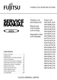
<strong>CHA</strong>/<strong>CLK</strong> - <strong>CHA</strong>/K2 DESCRIZIONE DELLA MACCHINA2 UNIT DESCRIPTIONQuesto capitolo ha lo scopo di fornire una descrizionegenerale delle caratteristiche principali della macchinanel suo insieme, unitamente a quella dei principali componenti,standard e opzionali.This chapter contains a general description of the mainunit characteristics, together with those of its principalstandard and optional components.2.1 IDENTIFICAZIONE2.1 IDENTIFICATION2.1.1 Identificazione della macchinaLa macchina si identifica tramite le targhette poste sultelaio e sul quadro elettrico. Le targhette riportano iseguenti dati:- Ragione sociale del costruttore- Indirizzo del costruttore- Designazione della serie e del tipo di unità- Numero di matricola- Anno di costruzione- Tipo e quantità di refrigerante- Massima pressione ammissibile- Taratura dei pressostati- Simbolo della certificazione CE- Caratteristiche elettriche- Identificazione schema elettrico2.1.1 Unit identificationThe unit can be identified throug the plats attached onthe frame and in the electrical box. This l<strong>ab</strong>el con tainsthe fol low ing in for ma tion:- Manufacturer’s name- Manufacturer’s address- Description of the series and type of unit- Series number- Year of construction- Type and quantity of refrigerant liquid- Max. Allow<strong>ab</strong>le pressure- Pressure switch set point- EC certification symbol- Electrical characteristics- Wiring diagram identificationG.I. HOLDING S.p.AVia Max Piccini, 11/1333050 RIVIGNANO (UD) - ITALYManufactured by BV.ITA.40.02.1230Modello/ModelMatricola/Serial numberModell/Modèle Matrikelnr/Matricule G.I. HOLDING S.p.AVia Max Piccini 11/13Tensioni-Fasi-Frequenza Tensioni circuiti ausiliari 33050 RIVIGNANO (UD)Voltage-Phases-Frequency Auxiliary circuit voltage ITALYSpannung-Phasen-Frequenz Hilfstromkreisspannung Tel. +39 0432 773220Tension-Phases-Fréquence Tension circuits auxiliaires Fax. +39 0432 773855VE-mail: info@clint.itCorrente massima assorbita Corrente massima di spunto Web: www.clint.itMax <strong>ab</strong>sorbed current Max starting current Manufactured by BV.ITA.40.02.1230Maximale Stromaufnahme Max Anlaufstrom DIRETTIVA 97/23/CE del 29 maggio 1997 (P.E.D.) cat ICourant maxi <strong>ab</strong>sorbéeCourant maxi de démarrageA A Modello/ModelTipo di refrigerante Carica refrigerante per circuito Modell/ModèleRefrigerant typeRefrigerant charge per circuitKältemittel Typ Kältemittelfüllung pro Kreislauf Matricola/Serial numberType de réfrigerant Charge de réfrigerant chaque circuit Matrikelnr/MatriculekgTaratura pressostato di alta Press. massima circuito idraulico Anno di costruzioneHigh pressure switch setting Max hydraulic circuit pressure Construction yearHD-Wächter Einstellung Max. Druck im hydraul. Kreislauf BaujahrPréssion maxi refrigerant Préssion maxi circuit hydraulique Année de f<strong>ab</strong>ricationBarBarGruppo del fluido frigorifero Data di produzione PS Max.Press.ammissibile28barALTAALTAHIGH PRESS.HIGH PRESS.HOCHDUCKHOCHDUCKHAUTEHAUTEGroup of the refrigerant fluid Manufacturing date Max Working press.Refrig.sideBASSAKältemittel Klasse Herstellungsdatum Max Betriebsdruck Kältemittelseitug20barLOW PRESS.NIEDERDUCKBASSEGroupe de fluide frigorifique Date de f<strong>ab</strong>rication Press.max.de travail cute refrigerant7
<strong>CHA</strong>/<strong>CLK</strong> - <strong>CHA</strong>/K2.2 DESTINAZIONE D’USOI <strong>CHA</strong>/<strong>CLK</strong> - <strong>CHA</strong>/K sono refrigeratori con condensazionead aria de sti na ti a raffreddare acqua (eventualmente ad di -zio na ta con glicole etilenico inibito) che circola in un anellochiuso. Le unità a pompa di calore pos so no, a se con dadel ciclo di funzionamento scelto, raffred da re o ri scal da rel’acqua dell’anello.Il caldo, o il freddo, così prodotto può essere utilizzato perimpianti di climatizzazione o per processi industriali.2.3 CONTROINDICAZIONINon impiegare in prossimità della macchinaprodotti infiamm<strong>ab</strong>ili.Non impiegare in prossimità della macchinasostanze in grado di formare misceleesplo si ve.Non impiegare la macchina dove sus si sto noproblemi di impatto ambientale (vedi pun to3.5 pag. 13).2.2 INTENDED USEThe <strong>CHA</strong>/<strong>CLK</strong> - <strong>CHA</strong>/K series of air condensation chillers havebeen de signed to cool water (possibly containing inhibitedeth yl ene glycol) circulating in a closed circuit. The heatpump units can cool or heat the water in the closed circuitdepending on which operating cycle is chosen.The heat or cold produced can be used for air-con di -tion ing systems or industrial processes.2.3 CONTRAINDICATIONSDo not use inflamm<strong>ab</strong>le products near theunit.Do not use substances that can form explosive mixtures near the unit.Do not use the unit in conditions that couldbe harmful for the environment (see point3.5 on page 13).2.4 DESCRIZIONE GENERALETutte le strutture sono realizzate in peraluman. La strut tu raè autoportante ed i pannelli sono facilmente rimovibiliin modo da permettere l’ac ces so all’interno della unitàper le operazioni di ma nu ten zio ne e riparazione.2.4 GENERAL DESCRIPTIONAll the unit structures are made from peraluman. Thestruc ture is free standing and the panels are easy toremove in order to allow access to the inside of the unitfor main te nance and repair operations.3 SICUREZZA3 SAFETY3.1 DEFINIZIONIIn questo documento verranno utilizzate le seguentide fi ni zio ni:- Zone pericolose: qualsiasi zona all’interno e/o inpros si mi tà della macchina in cui la presenza di unaper so na esposta costituisca un rischio per la sicurezzae la salute di detta persona.- Persona esposta: qualsiasi persona che si trovi in ter -na men te o in parte in una zona pericolosa.- Operatore/Manutentore: la o le persone incaricate difar funzionare, regolare, eseguire la manutenzione,ri pa ra re, movimentare la macchina.3.1 DEFINITIONThis document uses the following definitions:- Dangerous areas: any area inside and/or near to theunit in which the presence of a person would give riseto a risk for that person’s health.- Exposed person: anyone who is wholly or partly insidea dangerous area.- Operator/Maintenance man: person or persons authorised to operate, adjust, service, repair or movethe unit.8
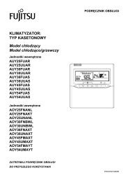
<strong>CHA</strong>/<strong>CLK</strong> - <strong>CHA</strong>/K3.2 REGOLE GENERALI DI SICUREZZAÈ vietato alle persone non autorizzate av vi -ci nar si alla macchina.Prima di ogni intervento di manutenzionesulla macchina, seguire scrupolosamentequanto indicato nel capitolo 9 a pag. 30.È vietata la rimozione delle protezioni e l’esclusionedei dispositivi di sicurezza e di emergenza.È vietato stazionare sulla macchina.3.2 GENERAL SAFETY REGULATIONSIt is forbidden for unauthorised persons toapproach the unit.Scrupulously observe the contents of chapter9 on page 30 before carrying out eachmaintenance operation on the unit.It is forbidden to remove safety guards andby-pass safety and emergency devices.It is forbidden to stand on the unit.- Impiegare la macchina solo per l’uso a cui essa èdestinata.- Il costruttore non risponde dei danni derivanti da unimpiego improprio della macchina o da modifichetec ni che effettuate sulla macchina.- Controllare regolarmente se i dispositivi di sicurezzapresentano un funzionamento corretto.- Non smontare, modificare o mettere fuori funzioneparti della macchina.- Per tutti gli interventi da effettuare sulla macchina,utilizzare esclusivamente attrezzi ed equipaggiamentiidonei e in buone condizioni. Gli operatori dovrannoindossare i normali dispositivi di protezione individuali(guanti, casco, occhiali, ecc.).- I lavori sull’equipaggiamento elettrico devono essereeseguiti solo da un elettricista qualificato.- Gli interventi sul circuito frigorifero possono essereeffettuati solo da personale specializzato.3.3 SIMBOLOGIAVerificare periodicamente lo stato delle targhette e provvede re, in caso di necessità, al loro ripristino.3.3.1 Mappa dei segnali di sicurezza- Only use the unit to do what it was built for.- The manufacturer declines all responsibility for dam agederiving from improper use or technical mod i ficationsmade to the unit.- Check the safety devices are in perfect working orderon a regular basis.- Do not dismount, modify or disconnect unit parts.- When working on the unit, only use suit<strong>ab</strong>le tools andequipment in good condition. Operators must wearnormal personal protection equipment (gloves, hel met,goggles, etc.).- Work on the electrical system of the unit may only becarried out by a qualified electrician.- Work on the refrigerant circuit may only be carried outby specialised staff.3.3 SYMBOLSCheck the state of the plates on a regular basis andrepair them if necessary.3.3.1 Location of safety signs581246 7 39
<strong>CHA</strong>/<strong>CLK</strong> - <strong>CHA</strong>/K3.3.2 Segnali di sicurezza 3.3.2 Safety signs1INGRESSO ACQUA REFRIGERATACHILLED WATER INLETKALTWASSEREINTRITTENTRÉE EAU GLACÉEUSCITA ACQUA REFRIGERATACHILLED WATER OUTLETKALTWASSERAUSTRITTSORTIE EAU GLACÉE23SFIATO ARIAAIR PURGEENTLÜFTUNGSVENTILPURGE AIR45RUBINETTO DI CARICOPLANT JWARGE SHUT OFF VALVEANLAGE DRUCK MIT ABSPERRVENTILROBINET DE JWARGE INSTALLATION68RUBINETTO DI SCARICOPLANT DISJWARGE SHUT OFF VALVEANLAGE ABFLUSS MIT ABSPERRVENTILROBINET DE DÉJWARGE INSTALLATION7- PRESENZA DI ORGANI IN MOVIMENTO- PRESENCE OF MOVING OBJECTS- ANWESENHEIT VON GEGENSTÄNDENIN BEWEGUNG- PRESENCE DES ORGANS EN MOUVEMENT10
<strong>CHA</strong>/<strong>CLK</strong> - <strong>CHA</strong>/K3.4 DISPOSITIVI DI EMERGENZAE DI SI CU REZ ZA3.4 EMERGENCY AND SAFETY DEVICESUn dispositivo di emergenza che tolga tensione dalla macchina deve essere previstoall’esterno della stessa a cura di chi installala macchina.An emergency external circuit breaker mustbe fitted by the unit installer to disconnectthe unit from the power supply.3.5 DESCRIZIONE DEL RISCHIO RESIDUO3.5 DESCRIPTION OF RESIDUE RISKSLa descrizione del rischio residuo prende in con si de r-azione i seguenti elementi:- a quale tipologia di pericoli è soggetto chi opera nell’ambi to della macchina;- la descrizione dei principali pericoli;- chi può essere esposto a tali pericoli;- quali sono le principali misure di sicurezza adottateper ridurre il rischio di infortuni.Le indicazioni per la prevenzione degli infortuni di seguitoriportate, con riferimento alle relative aree a rischiore si duo, devono essere integrate con tutte le indicazionigenerali del presente capitolo e con le norme dipre ven zio ne infortuni vigenti nel paese di de sti na zio nedell’impianto.The description of residue risks includes the followingelements:- the kind of danger the people working on the unit aresubjected to;- description of the main dangers;- who is exposed to such dangers;- the main safety methods used to reduce the risk ofinjury.The following accident prevention instructions, withref er ence to the relative areas concerned by residuerisks, must be integrated with all the general indicationscon tained in the present chapter and with theaccident prevention regulations in force in the countryof installation.3.5.1 Rischio residuo in prossimità della macchina- Folgorazione, se non vengono effettuati cor ret ta men tel’allacciamento elettrico e la messa a terra della macchina.- Tagli o escoriazioni per la presenza di superfici taglienti.- Aspirazione e successiva dispersione in ambientedelle sostanze presenti sul luogo dell’installazione.- Proiezione di eventuali oggetti che possano caderesulle pale dei ventilatori.- Fuoriuscita di acqua (in caso di anomalia).- Formazione di acqua di condensa e di ghiaccio nellazona antistante la macchina durante il funzionamentoin riscaldamento delle macchine a pompa di calore.- Alterazione del microclima (durante il fun zio na -mento).- Emissione di rumore (durante il funzionamento).- Fuoriuscita di olii (per anomalia).- Fuoriuscita del frigorigeno (per anomalia).N.B. Il frigorigeno è una sostanza ad effetto serra.Si tratta di vapori più pesanti dell’aria e chepossono provocare soffocamento riducendol’os si ge no disponibile per la respirazione. Unarapida eva po ra zio ne del liquido può causarecongelamento.3.5.1 Residue risks near the unit- Electrocution if the unit is not properly corrected tothe mains power supply and earth circuit.- Cuts or <strong>ab</strong>rasions caused by sharp surfaces.- Extraction and subsequent dispersion in the en vi -ron ment of substances present in the installationsite.- Ejection of objects falling on the fan blades.- Leaking water (in case of malfunction).- Formation of condensation and ice in front of the unitwhile the unit heat pumps are working.- Alteration of the micro climate (during operation).- Noise (during operation).- Leaking oil (in case of malfunction).- Leaking refrigerant liquid (in case of malfunction).N.B. Refrigerant liquid is a substance which causes agreenhouse effect. Its vapours are heavier thanair and can cause suffocation by reducing theamount of oxygen avail<strong>ab</strong>le for breath ing. Rapidevaporation of the liquid can cause freezing tooccur.11
<strong>CHA</strong>/<strong>CLK</strong> - <strong>CHA</strong>/K3.5.2 Misure da adottare in caso di fuoriuscitadi gas frigorigeno3.5.2 Measures to take in case of leakingrefrigerant gas- Tipo di prodotto:R410A- Misure di pronto soccorso:Informazione generale:non somministrare alcunchè a persone svenute.Inalazione:portare all’aria aperta. Ricorrere all’ossigeno o allarespirazione artificiale se necessario. Non som mi -ni stra re adrenalina o sostanze similari.Contatto con gli occhi:sciacquare accuratamente ed <strong>ab</strong>bondantementecon acqua per almeno 15 minuti e rivolgersi ad unmedico.Contatto con la pelle:Lavare subito <strong>ab</strong>bondantemente con acqua. To glier siimmediatamente tutti gli indumenti con ta mi na ti.- Misure in caso di fuoriuscita accidentale:Precauzioni individuali:evacuare il personale in aree di sicurezza. Pre ve de reuna ventilazione adeguata. Usare mezzi di pro te zio nepersonali.Precauzioni ambientali:intercettare l'emissione.Metodi di pulizia:impiegare prodotti assorbenti.- Product type:R410A- First aid measures:General information:Do not give anything to people who have fainted.Inhalation:take the person out into the open air. Use oxygenor artificial respiration if necessary. Do not giveadren a line or similar substances.Contact with eyes:carefully rinse with <strong>ab</strong>undant water for at least 15minutes and see a doctor.Contact with the skin:Wash with <strong>ab</strong>undant water and remove all con tam i-nated clothing immediately.- Measures to take in case of accidental leaking:Personal precautions:evacuate all staff to safety areas. Make sure thearea is suit<strong>ab</strong>ly ventilated. Use personal protectionequipment.Environmental precautions:to intercept the emission.Cleaning methods:to employ <strong>ab</strong>sorbent products.3.5.3 Operazioni con rimozione dei pannelliAlcune delle operazioni e/o verifiche di seguito descritterichiedono la rimozione dei pannelli del refrigeratore peraccedere all’interno dello stesso.3.5.3 Operations with the panels removedSome of the following operations and/or controls requirethe panels of the unit to be removed in order to accessthe inside of the unit.Prima di rimuovere qualsiasi pannello perime tra le, eccezion fatta per quello chepro teg ge il quadro elettrico, è ob bli ga to riotogliere tensione.Si fa presente che all’interno dell’unità, anche a macchina ferma possono esserci superfici calde (tubazioni,com pres so re, ecc.), o fredde (compressore, separatored’aspi ra zio ne, ecc.), taglienti (alette batterie) o corpi inmovimento (ventilatori).Pertanto tali operazioni devono essere effettua te solo da personale qualificato chein dos si indumenti di sicurezza.Before removing an outer panel, except forthe one protecting the electrical panel, theunit must be disconnected from the mainspower supply.Please note that some surfaces inside the unit may behot (piping, compressor, etc.), cold (compressor, suctionseparator, etc.), sharp (coil fins) or moving (fans) evenwhen the unit is not working.These operations may only be carried out byqualified staff wearing safety clothing.12
<strong>CHA</strong>/<strong>CLK</strong> - <strong>CHA</strong>/KVerifiche di funzionamento possono richiedere il fun zio -na men to (totale o parziale dell’unità) con un pannelloaperto. In tal caso il pannello va rimosso a macchinaferma.Queste verifiche sono particolarmente pe ri -co lo se e sono pertanto riservate a per so na lealtamente qualificato.Operare come segue:- Togliere tensione tramite il sezionatore generale.- Aprire il quadro elettrico e disattivare, togliendo irelativi fusibili, gli organi di cui non è necessario ilfun zio na men to per la verifica che si deve effettuare.- Richiudere il quadro elettrico.- Rimuovere il pannello interessato.- Avviare l’unità.- Effettuare le verifiche richieste con la massima cau te lae con l’utilizzo di protezioni individuali.- Completate le verifiche, arrestare l’unità e rimettereal suo posto il pannello precedentemente tolto.- Togliere tensione e rimettere al loro posto gli eventualifusibili precedentemente tolti.- Richiudere il quadro elettrico.Operating checks may require the unit to work (totallyor partially) while a panel is open. In this case the panelshould be removed when the unit is not working.These checks are particularly dangerous andmay only be carried out by highly qual i fiedstaff.Proceed as follows:- Turn off mains power with the main power switch.- Open the electrical panel and remove the relative fusesto disconnect the components that do not need to beworking in order to carry out the relative check.- Close the electrical panel.- Remove the panel in question.- Start the unit.- Carry out the relative check with the greatest of careand using personal protection equipment.- After completing the check, stop the unit and put thepanel back in place.- Turn off mains power and put back any fuses thatwere previously removed.- Close the electrical panel.13
<strong>CHA</strong>/<strong>CLK</strong> - <strong>CHA</strong>/K4. ISPEZIONE, TRASPORTO4.1 ISPEZIONEAll’atto del ricevimento dell’unità, verificarne l’integrità.Poiché la macchina è stata accuratamente controllataprima di lasciare la f<strong>ab</strong>brica, eventuali danni sono daimputare al trasportatore. Si raccomanda perciò di annotar li sul Foglio di Consegna prima di controfirmarlo.Avvisare tempestivamente la società o l’Agen te sul l’en ti tàdel danno riportato dall’unità.Il Cliente deve sempre compilare un rapporto scritto cheriguarda ogni eventuale danno subito dalla macchina.4.2 STOCCAGGIOLa temperatura dell’ambiente in cui vengono im ma gaz z-i na te le unità deve essere compresa tra -20 e +50°C.4.3 SOLLEVAMENTO E TRASPORTODurante lo scarico ed il posizionamento dell’unità, prestare molta attenzione alle manovre che non devono inalcun modo essere brusche e/o violente. Non utilizzarecome punti di sollevamento le tubature o altri com po -nen ti della macchina.Attenzione!In tutte le operazioni di sollevamento as si cu -rar si di aver ancorato saldamente l’unità perevitare ribaltamenti o cadute ac ci den ta li.4. INSPECTION AND TRANSPORT4.1 INSPECTIONCheck the condition of the unit on receipt. As the unit wascarefully checked before leaving the factory, any claimsfor damages should be addressed to the forwarder. Anydamage should therefore be indicated on the DeliveryNote before signing it.Please inform the company or the Agent of the natureof the damage to the unit immediately.The Customer must always write a report describingany damage caused to the unit.4.2 STORAGEThe temperature in the area where the units are storedmust range between -20 and +50°C.4.3 LIFTING AND TRANSPORTWhen unloading and positioning the unit, take great carenot to make sudden and/or violent manoeuvres. Do notlift the unit by its piping or any other components.The unit should only be moved as shown in the plateattached to it.Attention!Make sure the unit is securely anchoredbefore lifting it in order to prevent it fromaccidentally overturning or falling.4.4 DISIMBALLOL’imballo va tolto solo quando l’unità è giunta sul postodi installazione e non dovrà più essere movimentata.Rimuovere con cura l’imballo della macchina, evitandodi danneggiare la stessa.Poiché i materiali che costituiscono l’imballo sono dinatura diversa (legno, nylon, polistirolo, cartone, ecc.), siconsiglia di conservarli separatamente e di con se gnar lialle ditte specializzate nello smaltimento e nel riciclaggiodegli stessi allo scopo di salvaguardare l’am bien te.4.4 UNPACKINGOnly unpack the unit when it has reached the installationsite and no longer needs to be moved.Remove the packing material with care, making surenot to damage the unit.Given that various kinds of packing materials are used(wood, nylon, polystyrene, cardboard, etc.), they shouldbe separated and delivered to specialised disposal andrecycling companies for environmental reasons.14
<strong>CHA</strong>/<strong>CLK</strong> - <strong>CHA</strong>/K5 INSTALLAZIONE5.1 SCELTA DEL LUOGO DI INSTALLAZIONENella scelta del luogo di installazione si dovrà tenereconto di:- Peso dell’unità:La soletta di appoggio dell’unità deve es se reperfettamente orizzontale ed in grado di sopporta re il peso in funzionamento del l’uni tà.È opportuno costruire una soletta di supporto di di men -sio ni proporzionate all’unità. Ciò si rende in particolarmodo necessario quando l’unità deve es se re posta suterreno inst<strong>ab</strong>ile (giardini, terreni di riporto, ecc.).La soletta deve:• appoggiare su opportune fondamenta, avere un’altezza, rispetto al terreno circostante, di circa 10-15cm;• essere orizzontale ed in grado di sopportare circail 200% del peso di esercizio della macchina.- Spazi:È necessario verificare che gli spazi di rispettoriportati sul foglio dimensionale del l’uni tàsiano lasciati liberi.Ridurre lo spazio richiesto può significare difficoltà oimpossibilità di effettuare le operazioni di ma nu ten zio nee/o malfunzionamento dell’unità a causa di ri du zio nedella portata d’aria che investe la batteria con den san teo di ricircolo della stessa.Si fa presente che non sono ammessi ostacoli quali tettucci, pensiline o coperture ingenere al di sopra della macchina.Si tenga presente che le unità a pompa di caloredanno luogo a formazione di ghiaccio e condensa.Si dovrà per tan to prov ve de re a drenare l’acqua dicondensa e sbrinamento, raccolta dalla vaschettaraccogli condensa, per evitare che il pavimento diventisdruc cio le vo le.Tutta la zona di rispetto dovrà essere interdet ta, fatta eccezione per gli operatori emanutentori addetti alla macchina.- Rumore:Durante il suo funzionamento, l’unità genera del ru mo re;evitare pertanto l’installazione in ambienti ri ver be ran ti.L’unità dovrà essere posizionata con il lato batteria rivoltonella direzione in cui la rumorosità è meno critica.- Venti predominanti:Il vento può alterare le condizioni di funzionamento; perminimizzarne gli effetti si consiglia di posizionare l’unità con illato lungo parallelo alla direzione dei venti pre do mi nan ti.- Vibrazioni:I supporti antivibranti forniti di serie, permettono di eliminareeventuali vibrazioni prodotte dalla macchina.5 INSTALLATION5.1 CHOOSING THE INSTALLATION SITEWhen choosing the installation site the following pointsshould be considered:- The weight of the unit:The supporting surface under the unit mustbe perfectly horizontal and <strong>ab</strong>le to withstandits operating weight.A supporting surface with an appropriate area shouldbe built. This is particularly important if the unit is installedon unst<strong>ab</strong>le ground (gardens, embankments,etc.).The supporting surface must:• lie on suit<strong>ab</strong>le foundations and be <strong>ab</strong>out 10-15 cmhigher than the surrounding ground;• be horizontal and <strong>ab</strong>le to withstand <strong>ab</strong>out 200% ofthe weight of the unit in operation.- Spaces:Make sure that sufficient free space, as indicat ed on the scale drawing, is left aroundthe unit.Less space will make it difficult or impossible to carryout maintenance operations and/or lead to faults inthe unit due to the reduction in the air flow on thecondenser coil or its recirculation.Please note that obstacles such as canopies, shelters or coverings in general arenot permitted.Please note that the heat pump units cause ice andcondensation. This water, collected by the drain pan,must therefore be drained to prevent the floor frombecoming slippery.People may not enter the unit area unlessthey are authorised operators and main te -nance personnel.- Noise:The unit generates noise while it’s working; do notinstall it in reverberating rooms. The unit must be positionedwith the coil side facing the direction wherenoise is less critical.- Prevailing winds:Wind may alter operating conditions; to minimise itseffects the unit should be positioned with the long sideparallel to the direction of prevailing winds.- Vibrations:The shock <strong>ab</strong>sorbers, standard, allow to avoid possiblevibrations of the unit.15
<strong>CHA</strong>/<strong>CLK</strong> - <strong>CHA</strong>/K5.2 COLLEGAMENTO IDRAULICO5.2 WATER CONNECTIONS5.2.1 GeneralitàPer la realizzazione del circuito idraulico dell’acqua re fri -ge ra ta è buona norma seguire attentamente le indicazionisotto riportate oltre che la normativa vigente.5.2.1 GeneralPlease carefully carry out the following instructions andobserve current law when installing the chilled watercircuit.Attenzione!Le tubazioni idrauliche devono essere opportu na men te staffate per non gravare conil loro peso sul refrigeratore.- Raccordare le tubazioni al refrigeratore tramite giuntiflessibili al fine di evitare la trasmissione delle vi bra zio nie compensare le dilatazioni termiche.Attention!The water pipes must be suit<strong>ab</strong>ly supportedwith brackets in order not to weigh on thechiller.- Connect the pipes to the chiller with flexible joints inorder to prevent the transmission of vibrations and tocompensate thermal expansion.- Installare sulle tubazioni i seguenti componenti:• valvole di intercettazione (saracinesche) per isolarel’unità dal circuito idraulico;• indicatori di temperatura e pressione per la normalemanutenzione e controllo del gruppo;• pozzetti sulle tubazioni d’ingresso ed uscita per irilievi di temperatura, qualora non fossero presentiindicatori di temperatura;• filtro metallico (tubazione in ingresso) a rete conmaglia non superiore ad 1mm, per proteggere loscambiatore da scorie o impurità presenti nelletu ba zio ni;• valvola di taratura per la regolazione della portataacqua• valvole di sfiato, da collocare nelle parti più elevate delcircuito idraulico, per permettere lo sfogo del l’aria;• eventuale vaso di espansione supplementare,dimensionato in fun zio ne dellaquantità d’acqua contenuta nell’impiantoe delle escursioni termiche prevedibili.• valvole di carico automatico per il mantenimentodella pressione del sistema e per compensarele dilatazioni ter mi che del fluido.- Install the following components on the pipes:• shut-off valve (moisters) for shutting off the watermains;• temperature and pressure gauges for routine maintenance and inspection purposes;• check points on the inlet and outlet pipes for measuringtemperatures if temperature indicators are notfitted;• metal filter (inlet pipe) with a maximum mesh ap er tureof 1 mm to protect the exchanger from waste orimpurities in the pipes;• waterflow control valve• relief valves, fitted in the uppermost parts of thewater circuit, for expelling air;• eventual supplementary expansion tank of a suit<strong>ab</strong>lesize for the quantity of water contained in thesystem and the expected temperature range.• an automatic inlet valve for maintaining the pressureof the system and com pen sat ing the thermalexpansion of the fluid.16
<strong>CHA</strong>/<strong>CLK</strong> - <strong>CHA</strong>/K5.2.2 Evaporatore5.2.2 EvaporatorÈ di importanza fondamentale che l’in gres sodell’acqua avvenga in corrispondenza dellaconnessione contrassegnata con la targhetta“ENTRATA ACQUA”.Per gli attacchi idraulici vengono utilizzate connessionifilettate maschio (fare riferimento ai disegni dimensionali,così come per la posizione degli attacchi).È di fondamentale importanza realizzare ilcircuito idraulico in modo tale che vengagarantita la costanza della portata d’acquaallo scambiatore in qualsiasi condizione difunzionamento.It is vitally important that the water entersthe unit from the connection point markedwith the “WATER INLET” plate.Threaded male unions (please refer to the scale drawingswhich also show the position of the unions).It is vitally important to connect the watercircuit so that the flow of water to the exchanger is always constant under all op er -at ing conditions.Una valvola di sicurezza sul circuito idraulicofornita di serie, permetterà, in caso di anomaliegravi nell’impianto (ad es. in cen dio),di scaricare il sistema evitando possibiliscoppi. Collegare sem pre lo scarico ad unatubazione di diametro non inferiore a quellodell’apertura della val vo la e convogliarlo inzone nelle quali il getto non possa recaredanno alle persone.A safety valve, serially supplied, on the watercircuit. In case of serious system faults (e.g.fire) this will allow the system to be drainedin order to prevent the risk of ex plo sions.Always connect the drain to a pipe with adiameter not less than that of the valve openingand install the outlet in an area where thejet cannot cause harm to people.Attenzione!Durante le operazioni di allacciamento idraulico non operare mai con fiamme libere inprossimità o all’interno dell’unità.Attention!While connecting the water circuit, neverwork with naked flames near to or insidethe unit.17
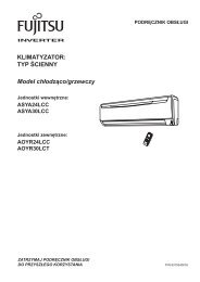
<strong>CHA</strong>/<strong>CLK</strong> - <strong>CHA</strong>/KSchema di collegamento impianto idraulicoHydraulic circuit connection diagramST<strong>CHA</strong>/<strong>CLK</strong>VSIST1VEMNSFAEWCARANTRICVFTRST2SCPDMPSFADENOMINAZIONEANTRIDESIGNATIONANTCVCAREWFTRMNMPPDRIRICGiunti antivibrantiValvola di ritegnoCaricoEvaporatoreFiltro a reteManometro acquaPompa di circolazionePressostato differenziale acquaValvola di intercettazione a sferaValvola carico acqua automaticoEWST1ST2PD<strong>CHA</strong>/KSFAMPANTRI CVRISFARIANT<strong>CHA</strong>/K/SPVEVEFTRVSIRISFASTRIMNRICVibration-proof jointsGate valveLoadEvaporatorMessh filterWater manometerCirculating pumpDifferential water pressure switchBall shut-off valveAutomatic water filling valveANTCVCAREWFTRMNMPPDRIRICSCSFAEWSTScarico acquaSfiato aria automaticoEvaporatoreSerbatoio inerzialeEWST1PDMPSTVSIMNSFAANTSFARICVFTRWater drainAutomatic air purgeEvaporatorInertial tankSCSFAEWSTST1ST2VESonda di lavoroSonda antigeloVaso d'espansioneST2<strong>CHA</strong>/K/STANTRISensor for unit operationAntifreeze sensorExpansion vesselST1ST2VEVSIValvola di sicurezzaST1VEPDMPVSIMNSFAANTRICVFTRSafety valveVSIEWSFAST2ANTRI5.3 COLLEGAMENTI ELETTRICI5.3 ELECTRICAL CONNECTIONS5.3.1 Generalità5.3.1 GeneralQueste operazioni devono essere effettuatesolo da personale specializzato.Prima di effettuare qualsiasi operazione suparti elettriche assicurarsi che non vi siatensione.Verificare che l’energia disponibile corrisponda ai dati nominalidell’unità riportati sulla targhetta (tensione, nu me rodi fasi, frequenza).These operations may only be carried outby specialised staff.Before carrying out any operations on electrical components, make sure the unit is disconnectedfrom the mains power supply.Make sure that the mains power supply corresponds tothe rated values of the unit shown on the plate (voltage,number of phases, frequency).18
<strong>CHA</strong>/<strong>CLK</strong> - <strong>CHA</strong>/KI collegamenti elettrici devono essere effettuati seguendoattentamente le istruzioni riportate sul quaderno tecnicoallegato all’unità.Il collegamento a terra è obbligatorio per legge. Si deveperciò provvedere al collegamento del cavo di terra conla barra di terra situata nel quadro elettrico e con tras -segnata con PE.L’alimentazione del circuito ausiliario è derivata dallalinea di potenza tramite un trasformatore situato nelquadro elettrico.La sezione del cavo e le protezioni di lineadevono essere conformi a quanto indicatonello schema elettrico e nell’apposita sche daallegata all’unità.Electrical connections must be made carefully followingthe instructions shown on the catalogue attachedto the unit.The earth connection is obligatory by law. The earthc<strong>ab</strong>le must be connected to the earth bar located inthe electrical panel and marked with PE.Auxiliary circuit power is supplied by the power line bymeans of a transformer located in the electrical panel.The cross-section of the c<strong>ab</strong>le and the lineprotections must comply with the in di ca tionsshown on the wiring diagram and in the relativesheet attached to the unit.Rispettare la sequenza delle fasi, viceversa la macchinanon potrà funzionare.La tensione di alimentazione non deve subire variazionisuperiori a ±5% e lo squilibrio tra le fasi deve esseresempre inferiore al 2%.Il funzionamento deve avvenire entro i va lo risopra citati, pena la decadenza im me dia tadella garanzia.Observe the phase sequence, otherwise the unit willnot work.Input voltage must not exceed variations of over ±5%and phase unbalance must always be less than 2%.Unit operation must always take place withinthe <strong>ab</strong>ove values as otherwise the guaranteewill immediately become null and void.Una eventuale pompa supplementare deveessere avviata prima della partenza delrefrigeratore e fermata dopo l’arresto diquest’ultimo (ritardo minimo con si glia to:40 secondi).A possible additional pump must be startedup before starting up the chiller while it mustbe stopped after the chiller has stopped (minimumrec om mend ed delay: 40 seconds).5.3.2 Consensi esterniQualora si desideri effettuare un ON-OFF remoto dell’unità è necessario collegare il consenso esterno aicontatti indicati sullo schema elettrico.Per il collegamento elettrico al contatto ON-OFF remotoe funzionamento CHILLER-POMPA DI CALORE remoto,non installare i cavi di comando all’interno delle canalineusate per i cavi di potenza; nel caso non fosse possibile,utilizzare un cavo schermato.Quando si effettuano i collegamenti de scrit tonel paragrafo 5.3.2 attenersi scru po lo s-a men te a quanto riportato nello schemaelettrico e nei kit di istruzione. I cavi di collegamentodevono ave re sezione minima di1,5 mm².5.3.2 External signalsIf a remote ON-OFF command is required, connect theexternal en<strong>ab</strong>le to the contacts shown on the wiringdiagram.For the electrical connection to the remote On-off con tactand remote Chiller heat pump operation, do not installdrive c<strong>ab</strong>les inside the ducts used for power c<strong>ab</strong>les; ifit is not possible, a shielded c<strong>ab</strong>le must be used.When making the connections describedin paragraph 5.3.2, carefully fol low the indicationsshown in the wiring di a gram andinstructions kit. The connecting c<strong>ab</strong>les musthave a min i mum cross-section of 1,5 mm².19
<strong>CHA</strong>/<strong>CLK</strong> - <strong>CHA</strong>/K6 AVVIAMENTO6.1 CONTROLLI PRELIMINARIAL L’AV VIA MEN TO-Verificare che i collegamenti elettrici siano stati ese gui ticorrettamente e che siano stati serrati tutti i morsetti.-Verificare che la tensione sui morsetti L 1, L 2, L 3, sia quellariportata sulla targa dell’unità (tolleranza am mes sa)±5% controll<strong>ab</strong>ile con un tester. Se av ven go no frequentivariazioni di tensione, si prega di con tat ta re l'ufficiotecnico di sede per la scelta di opportune pro te zio ni.- Controllare, eventualmente tramite l’ausilio di un cer ca -fu ghe, che non vi siano perdite di fluido refrigerante.6 START UP6.1 PRELIMINARY CONTROLS- Make sure that the electrical connections have beenmade correctly and that all the terminals have beenwell tightened.- Use a tester to make sure that the voltage on terminalsL 1, L 2, L 3, is equal to that shown on the rating plate(permitted tolerance ±5%). If voltage is subject to frequentvariations, please contact technical main officein order to decide on suit<strong>ab</strong>le protection devices.- Use a leak tester, if necessary to make sure there areno leaks of refrigerant liquid.-Verificare che le resistenze del carter (se presenti) sianocorrettamente alimentate.L’inserimento delle resistenze deve esserefatto almeno 12 ore prima dell’avviamento,ed avviene automaticamente alla chiusuradel sezionatore generale (posizione I).- Check that the heating elements of the sump (if fitted)are correctly powered.The heating elements must be turned onat least 12 hours before start up; this takesplace automatically when the main powerswitch is closed (position I).Per controllare se le resistenze funzionano cor ret ta -men te, verificare che la parte inferiore del com pres so resia ad una temperatura di 10÷15°C superiore a quellaambiente.To check if the heating elements work correctly, makesure that the lower part of the compressor is 10÷15°Chigher than room temperature.- Verificare il corretto collegamento del circuito idrau li co(de vo no essere rispettate le indicazioni sulle targhettea bordo macchina).- Check the water circuit is correctly connected (the indicationson the unit rating plate must be observed).- Assicurarsi che il circuito idraulico sia stato pre ven ti -vamen te pulito: si consiglia di effettuare un lavaggiodel circuito idraulico bypassando l’unità e quindi diverifi ca re lo stato di pulizia del filtro dell’impianto.- Make sure that the water circuit has been cleanedbeforehand: the water circuit should be washed, bypassing the unit, and then the system filter checkedfor dirt.- Le macchine vengono spedite con sfiati e drenaggiaperti. Apposite targhette indicano le loro posizioni.Essi vanno chiusi all’atto dell’installazione quando siriempie il circuito idraulico.- The units are despatched with the relief valves anddrains open. Special plates show where they are located. They must be closed during installation beforethe water circuit is filled.- Verificare che l’impianto idraulico sia stato sfiatato,eli mi nan do ogni eventuale residuo d’aria; l’operazioneva ese gui ta caricando gradualmente e aprendo idi spo si ti vi di sfiato disposti dall’installatore nella partesu pe rio re del l’im pian to (a tale proposito consultare lase zio ne 5.2).- Make sure the water circuit has been well vented toeliminate any air residues; this operation is carriedout by gradually loading and opening the relief valvesfitted to the uppermost part of the unit by the installer(please consult section 5.2 for further information).20
<strong>CHA</strong>/<strong>CLK</strong> - <strong>CHA</strong>/K- Qualora si utilizzi acqua glicolata si può spostare il setpoint antigelo, il valore deve essere pari al valore dellatemperatura di congelamento del fluido più 6K.»- In case water with glycol is used, the anti-freezing setpoint can be moved, the value must be equal to the valueof the freezing temperature of the fluid plus 6K.»Attenzione!Prima di procedere alla messa in funzionedell’unità, assicurarsi che tutti i pannelli dichiusura siano al loro posto e siano stati benfissati con le apposite viti.Attention!Before starting up the unit, make sure thatall the external panels are in place and fixedwith screws.21
<strong>CHA</strong>/<strong>CLK</strong> - <strong>CHA</strong>/K6.2 MESSA IN FUNZIONESelezionare tramite ponte elettrico tra i morsetti 17 e 00 ilciclo di funzionamento. Ponte aperto "Raffreddamento".Ponte chiuso "Riscaldamento".N.B.: questa operazione è richiesta solo per le unitàin versione a pompa di calore.6.2 START UPSelect the functioning cycle by electrical bypass betweenclamps 17 and 00. Open bypass “cooling”;closed bypass “heating”.N.B.: this operation is only required for the versionswith heat pump.Attenzione!La commutazione del ciclo di fun zio na men todovrebbe essere effettuata sta gio nal men te.Frequenti passaggi dal funzionamento estivoa quello invernale e viceversa sono sconsigliatipoiché possono provocare il cattivofunzionamento dei compressori con il loroconseguente danneggiamento.Avviare la macchina ed osservare che si verifichi quantosegue (le indicazioni tra parentesi si riferiscono ad unitàa pompa di calore avviate in ciclo di riscaldamento).Dapprima si avvia la pompa e, se la temperaturadel l’ac qua di ritorno dall’impianto è sufficientementealta (bas sa), dopo circa 2½ minuti si avvieranno au to -ma ti ca men te i ventilatori, e dopo circa 40 secondi, ilcompressore.Al diminuire (aumentare) della temperatura dell’acqua diritorno dall’impianto avverrà l’arresto del com pres so re.Assieme al compressore si arresteranno anche i ven ti -la to ri mentre resterà in funzione la pompa di cir co la zio neacqua.Al risalire (ri<strong>ab</strong>bassarsi) della temperatura dell’acquadi ritorno dall’impianto si riavvierà il compressore even go no avviati tutti i ventilatori.Se la macchina non si avvia, consultare il capitolo 9,parte prima.Attention!The operating cycle should be changed on aseasonal basis. Frequent changes betweensummer and winter modes should be avoid edas they can cause the compressors to workbadly and consequently damage them.Start the unit and make sure the following hap pens(indications between brackets refer to units with heatpumps working in the heating cycle mode).First start the pump and, if the temperature of the returningwater from the playt is high (low) enough, the fanswill start up automatically after <strong>ab</strong>out 2½ minute, after<strong>ab</strong>out 40 sec. later the compressor.When the temperature of the water returning from theunit decreases (increases), the compressor will stop.The fans will stop together with the compressor whilethe water circulation pump will remain operating.When the temperature of the water returning from theunit increases (decreases) the compressor will start upas well as all the fans.If the unit doesn’t start, please consult chapter 9, partone.Si raccomanda di non togliere tensioneal l’uni tà durante i periodi di arresto. Laten sio ne va tolta solo per pause prolungate(ad esempio per fermate stagionali). Per lospe gni men to temporaneo dell’unità, seguireat ten ta men te le istruzioni riportate nelpa ra gra fo 7.The power supply must not be switched offwhile the unit is stopped. Power should onlybe switched off for prolonged pauses (e.g.seasonal shut downs). To shut down the unitfor short periods, please carefully follow theinstructions shown in paragraph 7.22
<strong>CHA</strong>/<strong>CLK</strong> - <strong>CHA</strong>/K6.3 VERIFICHE DURANTE IL FUNZIONAMENTO6.3 CHECKS DURING UNIT OPERATION6.3.1 Generalità- Controllare che la macchina non generi rumori ano ma lio vibrazioni eccessive.6.3.1 General- Check the unit for strange sounds or excessive vi bra -tions.- Controllare che la sequenza precedentemente descritta si ripeta regolarmente, lasciando in funzione ilcom pres so re per almeno 10 minuti (se così non fossesi dovrà aumentare l’inerzia dell’impianto).- Check that the <strong>ab</strong>ove sequence is repeated regularly,leaving the compressor working for at least 10min utes (if this is not the case, unit inertia must bein creas es).- Dopo alcuni minuti dall’avviamento del compressore,durante il ciclo di funzionamento estivo, assicurarsiche la temperatura di condensazione sia di 18±4Ksuperiore alla temperatura dell’aria in ingresso alcondensatore e che la temperatura di evaporazionesia di circa 5K inferiore alla temperatura dell’acqua inuscita dal l’eva po ra to re (a seconda della grandezzadel refrigeratore, del gas refrigerante usato e dellatemperatura ambiente).- A few minutes after the compressor start during thesummer operating cycle, make sure the condensationtemperature is 18 ± 4K higher than the temperatureof the air entering the condenser (depending on thesize of the chiller, the kind of refrigerant gas usedand the room temperature) and that the evaporatingtem per a ture is <strong>ab</strong>out 5K less than the temperature ofthe water leaving the evaporator.- Verificare che la temperatura del surriscaldamento delfluido frigorigeno sia compresa tra 5 e 7K. Per fareciò, rilevare la temperatura da un termometro a contatto posto sul tubo di aspirazione del compressore equella indicata sulla scala di un manometro connessoan ch’es so in aspirazione: la loro differenza fornisce ilvalore del surriscaldamento.- Make sure that the overheating temperature of therefrigerant lies between 5 and 7K. Do this by measuringthe temperature with a contact thermometer placed onthe suction pipe of the compressor and that indicatedon a pressure gauge connected to the suction line aswell: the difference between the two gives the valuesof overheating.- Verificare che la temperatura del sottoraffreddamentodel fluido frigorigeno sia compresa tra 4 e 8K. Per fareciò, rilevare la temperatura da un termometro a con tat toposto sul tubo di uscita dal condensatore e quella indicatasulla scala di un manometro connesso an ch’es sosulla presa del liquido all’uscita del con den sa to re: la lorodifferenza fornisce il valore di sot to raffreddamento.- Make sure that the subcooling temperature of therefrigerant fluid lies between 4 and 8K. Do this bymeasuring the temperature with a contact ther mom e terplaced on the suction pipe of the compressor andthat indicated on a pressure gauge connected to thesuction line as well: the difference between the twogives the values of subcooling.- Verificare, durante il funzionamento, l’assorbimentoelettrico della pompa dell’acqua deve corrispondere aquanto indicato nel quaderno tecnico. In caso contrariosignifica che la pompa non sta lavorando in curva.- Verify, during the operation, the electrical <strong>ab</strong>sorptionof the water pump: it must correspond to the dataindicated on the catalogue. In contrary case it meansthat the pump is not working in curve.23
<strong>CHA</strong>/<strong>CLK</strong> - <strong>CHA</strong>/K6.3.2 Sbrinamento(Solo unità a pompa di calore)Durante il funzionamento in ciclo invernale (pompa dicalore), la batteria lavora come evaporatore, raf fred -dan do e deumidificando l’aria esterna. A seconda dellecon di zio ni termoigronometriche dell’aria esterna, si avràla for ma zio ne di condensa o di brina.La brina accumulata sulla batteria ostruisce il passaggiodell’aria, riducendo la portata della stessa e con se guentementela resa termica.Le unità a pompa di calore sono provviste di organi dicontrollo che provvedono allo sbrinamento automaticodella batteria qualora ve ne fosse la necessità. Tale controlloprevede una sonda di pressione, la quale, quandola pressione rilevata eguaglia o è inferiore al punto ditaratura, attiva il consenso allo sbrinamento, che avràluogo solo se c’è stato un in ter val lo di tempo minimodall’ultimo sbrinamento.6.3.2 Defrosting(Only heat pump units)During operation in the winter cycle (heat pump), thecoil works as an evaporator, cooling and dehumidifyingthe external air. Depending on the temperatureand moisture of the external air, condensation orfrost will form.The frost accumulated on the coil obstructs the airinlet thereby reducing air flow and the heat transferrate.The heat pump units are fitted with control devices thatautomatically defrost the coil whenever necessary.This control device features a pressure probe, whenthe pressure is equal to or lower than the set-point,activates the defrost cycle function which will takeplace only if a certain time has elapsed since the lastdefrosting proc ess.Lo sbrinamento avviene nel modo seguente:- diminuisce la velocità dei ventilatori;- tramite la valvola a 4 vie viene invertito il ciclo difunzionamento e facendo così funzionare la batteriaalettata come condensatore. Il calore di con den sa zio neprovoca lo scioglimento della brina che si riversa nellavaschetta raccogli condensa.Quando viene raggiunta la pressione im po sta ta di finesbrinamento, la valvola a 4 vie viene nuo va men te in ver ti ta,ri pri sti nan do il ciclo di fun zio na men to in ver na le.Lo sbrinamento dura mediamente da 1 a 3 minuti eviene comunque interrotto dopo 3 minuti anche se nonè stato raggiunto il valore di set-point della pres sio nedi fine sbrinamento.Defrosting takes place as follows:- decrease fans speed;- the operating cycle is inverted with the 4-way valve,thereby making the finned coil work like a condenser.The condensation heat causes the frost to melt anddrain to the drain pan.When the end-of-cycle pressure is reached, the 4-wayvalve is inverted once more and the winter op er at ingcycle continues.Defrosting lasts from <strong>ab</strong>out 1 to a maximum of 3 minuteswhen it is interrupted even if the end-of-cycle pressureset-point has not been reached.6.4 ARRESTO DEL GRUPPOLa fermata del gruppo avviene premendo il tasto “OFF”posto sulla maschera del microprocessore.Attenzione!Per la fermata del gruppo non togliere tensione con l’interruttore generale poiché,così facendo, non verrebbero alimentate lere si sten ze del carter, con pregiudizio perl’in te gri tà del compressore alla ripartenza.6.4 STOPPING THE UNITStop the unit by pressing the “OFF” key placed on themicroprocessor front.Attention!Do not stop the unit by turning off the mainpower switch as this would also disconnectthe heating elements of the sump whichwould affect compressor operation afterstart up.24
<strong>CHA</strong>/<strong>CLK</strong> - <strong>CHA</strong>/K7 FUNZIONAMENTO7 OPERATION7.1 GENERALITÀLa macchina va avviata ed arrestata tramite il pulsanteON/OFF posto sulla mascherina del microprocessore.Compressori e ventilatori si avvieranno e si fermerannoautomaticamente in funzione della temperaturadel l’ac qua di ritorno dall’impianto mentre la pompa dicircolazione resterà in funzionamento continuo.Se qualcosa di anomalo dovesse avvenire la macchinaandrà in blocco totale o parziale dando una se gna la zio nedi allarme e visualizzando sul display del mi cro pro ces so requale delle sicurezze ha bloccato il fun zio na men to.Prima di ripristinare il funzionamento dell’unità si dovràaccertare ed eliminare la causa che ha generato ilblocco.Per ripristinare alcune sicurezze è necessario, oltre alnormale ripristino da tastiera; intervenire sull’organo disicurezza riarmandolo.7.1 GENERALStart and stop the unit with the ON/OFF button locatedon the microprocessor cover.The compressors and fans will automatically start andstop depending on the temperature of the water returningfrom the unit while the circulation pump will remainworking continuously.If a fault should occur, the unit will totally or partially blockand will give an alarm signal; the microprocessor displaywill indicate which safety device was activated.Before resetting the unit, the reasons for the block mustbe identified and eliminated.Some safety devices must be reset both physically andfrom the keyboard.Tali operazioni devono essere effettuate dapersonale specializzato.È VIETATO MANOMETTERE LE SI CU -REZ ZE.These operations must be carried out byspecialised staff.IT IS FORBIDDEN TO TAMPER WITH SAFE TYDEVICES.7.2 FERMATA STAGIONALEQualora si preveda una lunga fermata dell’impianto e sivoglia di conseguenza togliere tensione alla macchina, cisi dovrà accertare quale è la minima temperatura a cuipuò essere soggetta la macchina. Se questa è inferioreal punto di congelamento del fluido contenuto negliscambiatori, questi dovranno essere drenati. Inoltre perdrenare ulteriormente l'acqua residua, utilizzare l'ap po -si ta valvolina di scarico acqua, posta sul tubo ingressoacqua evaporatore.7.2 SEASONAL SHUT DOWNIf the unit is planned to be shut down for a long time andthe unit is required to be disconnected from the mainssupply, the minimum temperature to which the unit maybe subjected must be identified. It this is lower than thefreezing point of the fluid contained in the exchangers,these must be drained. Furthermore, in order to furtherdrain the outstanding water, use the suit<strong>ab</strong>le little dischargevalve, placed on the pipe of the wather inlet tothe evaporator.25
<strong>CHA</strong>/<strong>CLK</strong> - <strong>CHA</strong>/K8 RICERCA GUASTIPROBLEMA POSSIBILI CAUSE INTERVENTO CONSIGLIATOI.IL GRUPPO NONPARTE1. Manca il consenso del pressostato differenziale2. C'è un errato collegamento oppure sono aperti i contatti3. Il compressore è difettoso4. Mancano i consensi esterni5. Manca il consenso della sonda di lavoro6. Manca il consenso dell'antigelo (+)7. Manca il consenso di un dispositivo di sicurezza (+)8. È attivo il timer antiriciclo9. Intervengono i relè termici dei ventilatori (+)1. Sfiatare il circuito idraulico;verificare il funzionamento delle pompe,controllare l'apertura dei rubinetti.2. Controllare la sequenza delle fasi, controllare il voltaggio e chiudere i contatti.3. Vedere il punto II.4. Verificare il funzionamento delle pompe di circolazione acqua , del pressostatodifferenziale, sfiatare l'impianto. Verificare ulteriori consensi esterni.5. Impianto in temperatura, mancanza di richiesta. Controllare la taratura ed il funzionamento.6. Verificare taratura e funzionamento.7. Vedere punto IV o V.8. Attendere circa 5 minuti.9. Vedere punto VI.II.NON PARTE UNCOMPRESSORE1. Il compressore è bruciato2. Il circuito di potenza è aperto3. La protezione del motore è aperta (+)4. Il teleruttore del compressore è diseccitato1. Sostituirlo.2. Chiudere l'automatico del compressore dopo avere ricercato la causa diintervento della protezione.3. Il compressore ha lavorato in condizioni critiche oppure la carica di refrigeranteè scarsa. Verificare le condizioni di lavoro e vedere il punto VII.4. Ispezionare la tensione ai capi della bobina del compressore e la continuitàdella bobina. Sostituire se difettosa.III.PARTENZE EDARRESTIRIPETUTI DELCOMPRESSORE1. Il compressore è difettoso2. Il pressostato di minima interviene (+)3. Il teleruttore del compressore è difettoso4. Sono errati i valori di taratura del set-point5. Manca refrigerante1. Ispezionarlo ed eventualmente sostituirlo.2. Vedere punto V.3. Controllare ed eventualmente sostituire.4. Modificarli facendo riferimento ai dati riportati sulla programmazione del microprocessore.5. Vedere punto VII.IV.NON PARTE ILCOMPRESSOREPERCHÉ INTER-VIENE IL PRES-SOSTATO DIMASSIMA (+)1. Il pressostato non funziona2. C'è un'eccessiva carica di refrigerante3. C'è presenza di gas incondens<strong>ab</strong>ili nel circuito frigorifero4. Il filtro del refrigerante è intasato5. Sono intasati i filtri metallici (se presenti) del condensatore.La portata d'aria è troppo bassa *6. I ventilatori del condensatore non funzionano *7. Presenza di aria nel circuito idraulico **8. La pompa di circolazione è difettosa **1. Controllare e sostituirlo.2. Rimuovere l'eccesso di refrigerante dall'impianto.3. Scaricare il circuito, produrre il vuoto, quindi procedere ad una nuovacarica.4. Controllare e sostituirlo.5. Pulire i filtri con aria compressa o con acqua.6. Vedere punto VI.7. Sfogare il circuito idraulico.8. Controllare la pompa ed eventualmente procedere alla sostituzione.V.NON PARTE UNCOMPRESSOREPERCHÉ INTER-VIENE IL PRES-SOSTATO DIMINIMA (+)1. Il pressostato non funziona2. La macchina è completamente scarica3. La valvola di espansione termostatica non funzionacorrettamente4. Il filtro del refrigerante è intasato5. Sono intasati i filtri metallici dell'evaporatore. La portatad'aria è troppo bassa **6. I ventilatori dell'evaporatore non funzionano **7. C'è presenza di brina sulla batteria evaporante **8. La pompa di circolazione dell'acqua è difettosa *1. Controllare e sostituirlo.2. Vedere punto VII.3. Controllare, pulire ed eventualmente sostituirla.4. Controllare e sostituirlo.5. Pulire i filtri con aria compressa o con acqua.6. Vedere punto VI.7. Vedere punto XIII.8. Controllare la pompa ed eventualmente procedere alla sostituzione.(+) L'intervento delle sicurezze è evidenziato dal mi cro -pro ces so re (vedere manuale allegato).* Funzionamento solo in raffreddamento.** Funzionamento solo in riscaldamento26
<strong>CHA</strong>/<strong>CLK</strong> - <strong>CHA</strong>/K8 RICERCA GUASTIPROBLEMA POSSIBILI CAUSE INTERVENTO CONSIGLIATOVI.NON PARTONO IVENTILATORI1. Il teleruttore dei ventilatori è diseccitato2. Intervengono i relè termici dei ventilatori (+)3. Le connessioni sono errate4. Il motore del ventilatore è difettoso1. Ispezionare la tensione ai capi della bobina del teleruttore e la continuitàdella bobina. Sostituire se difettosa.2. Ispezionare l'isolamento tra gli avvolgimenti e tra gli stessi e la massa.3. Verificare e serrarle.4. Verificare ed eventualmente sostituirlo.VII.MANCARE FRI GE RAN TE1. C'è una perdita nel circuito frigorifero1. Dopo aver messo in pressione il circuito a circa 10 bar, controllarlo conun cercafughe. Riparare, fare il vuoto e caricarlo di refrigerante.VIII.IL TUBO DELLIQUIDO È CALDO1. C'è una insufficiente carica di refrigerante1. Vedere il punto precedente (VII).IX.IL TUBO DELLIQUIDO È BRINATO1. Il filtro del liquido è intasato1. Sostituire la cartuccia del filtro o il filtro stesso (a seconda dei modelli).X.IL GRUPPOCON TI NUA AFUNZIONARE SENZAMAI ARRESTARSI1. Manca gas refrigerante2. Il compressore non dà la resa frigorifera prevista3. C'è un eccessivo carico termico4. La taratura del termostato di funzionamento è errataoppure esso è rotto5. Il filtro del liquido è intasato1. Vedere il punto VII.2. Ispezionare, sostituirlo o revisionarlo.3. Ridurre il carico termico.4. Verificare la taratura del termostato ed eventualmente procedere allasostituzione dello stesso.5. Sostituirlo.XI.IL GRUPPO FUNZIONAIN MANIERAREGOLARE MA HA UNARESA INSUFFICIENTE1. La carica di refrigerante è scarsa2. C'è presenza di umidità nel circuito frigorifero1. Vedere punto VII.2. Svuotare il circuito frigorifero, essiccarlo, sostituire il filtro rifare la caricaXII.È BRINATO IL TUBODI ASPIRAZIONE DELCOMPRESSORE1. La valvola di espanisone termostatica non funzionain ma nie ra corretta2. La carica di refrigerante è scarsa3. Il filtro sulla linea del liquido è intasato4. La pompa di circolazione dell'acqua è difettosa *1. Controllare, pulire ed eventualmente sostituirla.2. Vedere punto VII.3. Pulirlo o sostituirlo.4. Ispezionare la pompa e sostituirla, se necessario.XIII.NON VIENE MAIATTUATO IL CICLO DISBRINAMENTO1. È diseccitata la valvola di inversione a 4 vie **2. Il valore di taratura del termostato di sbrinamento èerrato oppure la sonda è difettosa **1. Devono essere controllate l'alimentazione e le bobine delle valvole. Eventualmentela valvola di inversione va sostituita.2. Modificare il valore di taratura o, eventualmente, sostituire la sonda.XIV.IL SISTEMAPRODUCE RUMORIANOMALI1. Il compressore è rumoroso2. La valvola termostatica è rumorosa3. Ci sono vibrazioni nelle tubature4. I pannelli vibrano1. Contorllare e, se necessario, sostituirlo.2. Controllare e aggiungere refrigerante.3. Staffare i tubi.4. Regolare in maniera corretta i fissaggi.(+) L'intervento delle sicurezze è evidenziato dal mi cro -pro ces so re (vedere manuale allegato).* Funzionamento solo in raffreddamento.** Funzionamento solo in riscaldamento27
<strong>CHA</strong>/<strong>CLK</strong> - <strong>CHA</strong>/K8 TROUBLE SHOOTINGPROBLEM POSSIBLE REASONS RECOMMENDED AC TIONI.THE UNITDOESN'T START1. No differential pressure switch agreement2. The connections are faulty or the con tacts are open3. The compressor's faulty4. The external en<strong>ab</strong>les have not been given5. The work probe en<strong>ab</strong>le has not been given6. The antifreeze en<strong>ab</strong>le has not been given (+)7. A safety device en<strong>ab</strong>le has not been given (+)8. The anti-recirculation timer is active9. The fan thermal cut-outs trip (+)1. Give off idraulic circuit, verify the right running of pumps and if valves are open2. Check the phase sequence, check the voltage and close the con tacts.3. See point II.4. Check the water circulation pump and the differential water pressureswitch, and vent the circuit. Check further external en<strong>ab</strong>les.5. System on temperature, no cooling demand. Check adjustment and operation.6. Check adjustment and operation.7. See points IV or V.8. Wait for <strong>ab</strong>out 5 minutes.9. See point VI.II.A COMPRESSORDOESN'T START1. The compressor has blown2. The power circuit is open3. The motor protection is open (+)4. The compressor contactor is dis<strong>ab</strong>led1. Replace.2. Close the compressor circuit breaker after identifying the reason why itcut in.3. The compressor was working in critical con di tions or there isn't enoughrefrigerant. Check the work conditions and see point VII.4. Check the voltage at the ends of the contactor coil and the continuity ofthe coil.Replace if faulty.III.THECOMPRESSORSTARTS ANDSTOPSREPEATEDLY1. The compressor's faulty2. The low pressure switch has cut in (+)3. The compressor contactor is faulty4. The set-point values are incorrectly set5. There's not enough refrigerant liquid1. Check and replace if necessary.2. See point V.3. Check and replace if necessary.4. Modify them by referring to the information shown on the microprocessorprogramme.5. See point VII.IV.THE COMPRESSORDOESN'T STARTBECAUSE THEHIGH PRES SU RESWITCH HAS CUTIN (+)1. The pressure switch doesn't work2. There's too much refrigerant liquid3. There's non condens<strong>ab</strong>le gas in the refrigerant circuit4. The refrigerant filter is clogged5. The metal filters of the condenser (if fitted) are clogged.The air flow is too low *6. The condenser fans do not work *7. There's air in the water circuit **8. The circulation pump is faulty **1. Check and replace.2. Remove the excess refrigerant liquid from the system.3. Drain the circuit, pressurise and recharge the unit4. Check and replace.5. Clean the filters with compressed air or water.6. See point VI.7. Vent the water circuit.8. Check the pump and replace if necessary.V.A COMPRESSORDOESN'T STARTBECAUSE THELOW PRES SU RESWITCH HAS CUTIN (+)1. The pressure switch doesn't work2. The unit is completely empty3. The thermostatic expansion valve doesn't work properly4. The refrigerant filter is clogged5. The metal filters of the evaporator (if fitted) areclogged. The air flow is too low **6. The evaporator fans do not work **7. The evaporating coil is covered with frost **8. The water circulation pump is faulty *1. Check and replace.2. See point VII.3. Check, clean and replace if necessary.4. Check and replace.5. Clean the filters with compressed air or water.6. See point VI.7. See point XIII.8. Check the pump and replace if necessary(+) The microprocessor indicates when the safety devicescut in (see attached manual).* Operation only during cooling cycle.** Operation only during heating cycle.28
<strong>CHA</strong>/<strong>CLK</strong> - <strong>CHA</strong>/K8 TROUBLE SHOOTINGPROBLEM POSSIBLE REASONS RECOMMENDED AC TIONVI.THE FANS DON'TSTART1. Fan contactor is not energised2. The fan thermal cut-outs trip (+)3. The connections are faulty4. The fan motor is faulty1. Check the voltage at the ends of the contactor coil and the continuityof the coil. Replace if faulty.2. Inspect the insulation between the windings and between the windingsand the earth.3. Check and tighten.4. Check and replace if necessary.VII.LACK OFREFRIGERANTLIQUID1. There's a leak in the refrigerant circuit1. After pressurising the circuit at <strong>ab</strong>out 10 bar, check with a leak tester.Repair, depressurise and fill with refrigerant liquid.VIII.THE FLUID PIPEIS HOT1. There's not enough refrigerant liquid in the circuit1. See previous point (VII).IX.THE FLUID PIPE ISCOVERED WITHFROST1. The fluid filter is clogged1. Replace the filter cartridge or the filter (depending on the model).X.THE UNIT CON TI -NUES TO WORK WI-THOUT STOPPING1. Lack of refrigerant gas2. Compressor not performing as expected3. The heat load is excessive4. The thermostat is badly adjusted or broken5. The liquid filter is clogged1. See point VII.2. Inspect and replace or overhaul.3. Reduce the heat load.4. Check the thermostat set-point and replace the thermostat if necessary.5. Replace.XI.THE UNIT WORKSREGULARLY BUTHAS AN INSUFFI-CIENT OUT PUT1. There isn't enough refrigerant liquid2. Moisture in the refrigerant circuit1. See point VII.2. Empty the cooling circuit, dry it, replace the filter - do the charge againXII.THE COMPRESSORSUCTION LINE ISCOVERED WITHFROST1. The thermostatic expansion valve doesn't work properly2. There isn't enough refrigerant liquid3. The filter on the liquid line is clogged4. The water circulation pump is faulty *1. Check, clean and replace if necessary.2. See point VII.3. Clean or replace.4. Inspect the pump and replace it if necessary.XIII.THE DEFROSTINGCY CLE IS NEVERACTUATED1. The 4-way inversion valve is not energised**2. The defrosting thermostat set-point is incorrect or theprobe is faulty **1. Check valve coils. Replace the inversion valve if necessary.2. Change the set-point or replace the probe if necessary.XIV.ABNORMAL NOISEIN THE SYSTEM1. The compressor is noisy2. The thermostatic valve is noisy3. There are vibrations in the piping4. The panels vibrate1. Check and replace if necessary.2. Check and add refrigerant liquid.3. Fix the pipes with brackets.4. Install correctly.(+) The microprocessor indicates when the safety devicescut in (see attached manual).* Operation only during cooling cycle.** Operation only during heating cycle.29
<strong>CHA</strong>/<strong>CLK</strong> - <strong>CHA</strong>/K9 MANUTENZIONE E CONTROLLIPERIODICI9 ROUTINE MAINTENANCE ANDCONTROLSAVVERTENZEWARNINGSPrima di effettuare qualsiasi intervento sull’unità o di accedere a parti interne, as si cu -rar si di aver tolto tensione alla macchina.Poiché la tubazione di mandata del com pres -so re ha temperature elevate, si rac co man dadi prestar particolare attenzione quan do siopera nelle vicinanze di essa.Before carrying out any work on the unitor accessing internal parts, make sure theunit is disconnected form the mains powersup ply.Given the compressor delivery pipe hightemperature, special attention should bepaid when working near pipe and wait forthe pipe to cool.Se si deve operare in prossimità delle batterie alettate, prestar particolare attenzionealle alette in alluminio in quanto esse sonoparticolarmente taglienti.When working near the finned coils, payspecial attention to the aluminium fins asthese are particularly sharp.Una volta effettuate le operazioni di ma nu ten -zio ne, si raccomanda di richiudere sem prel’unità tramite le apposite pannellature, chevanno fissate con le viti di serraggio.After maintenance operations have beencompleted, the unit should always be closedwith the relative panels which should be fixedwith the relative screws.Si tenga presente che tutte le operazionidescritte in questo capitolo DEVONO ES-SE RE ESEGUITE SOLO DA PERSONALEQUA LI FI CA TO CON USO DI PROTEZIONIIN DI VI DUA LI.Please remember that all the operationsde scribed in this chapter MUST ONLY BECAR RIED OUT BY QUALIFIED STAFF WEAR-ING PERSONAL SAFETY EQUIPMENT.9.1 GENERALITÀ9.1 GENERALÈ buona norma eseguire controlli periodici all’unità, alfine di verificarne il corretto funzionamento. Di seguitovengono descritti i controlli da eseguire mensilmentee ogni 4 mesi. Inoltre, nel caso si prevedano lunghiperiodi di inattività della macchina, e se le temperatuream bien te sono inferiori al punto di congelamento delfluido utilizzato, va scaricato il fluido dalle tubazioni edagli scambiatori di calore.The unit should be controlled periodically to make sureit works correctly. The controls that should be made ona monthly and four-monthly basis are described below.Furthermore, if the unit is not expected to be used fora long period, and if the room temperatures are lowerthan the fluid freezing point, the fluid should be drainedfrom the piping and the heat exchangers.30
<strong>CHA</strong>/<strong>CLK</strong> - <strong>CHA</strong>/K9.1.1 Controlli mensili- Verificare il serraggio dei morsetti sia all’interno delquadro elettrico che nella morsettiera dei com pres -so ri.- Controllare i contatti mobili e fissi dei teleruttori, sostituendoliin caso di deterioramento.- Controllare che il compressore non perda olio.- Controllare che il circuito idraulico non perda acqua.- Spurgare l’impianto idraulico.- Verificare che il pressostato differenziale acqua fun zio niin ma nie ra cor ret ta.- Controllare i riscaldatori del carter dei compressori.- Pulire i filtri metallici nelle tubazioni idrauliche.- Pulire la batteria alettata (ed i relativi filtri metallici,se presenti), utilizzando un getto d’aria compressaope ran do in senso inverso rispetto al flusso dell’aria.Nel caso i filtri siano particolarmente intasati, operareutilizzando un getto d’acqua.- Verificare che le emissioni sonore della macchina sianoregolari.9.1.2 Controlli quadrimestrali- Procedere alla verifica dello stato di fissaggio, di bilancia men to e di condizioni generali delle ventole.9.2 RIPARAZIONI DEL CIRCUITO FRIGOVanno effettuate solo da personale specializ za to, utilizzando le normali tecnicheti pi che degli impianti di refrigerazione cheim pie ga no fluidi alogeni quali frigorigeni.9.1.1 Monthly controls- Make sure the terminals in the electrical panel and inthe compressor terminal board are well tightened.- Check the fixed and mobile contacts of the contactorsand replace them if they are worn.- Make sure no oil is leaking from the compressor.- Make sure that no water is leaking from the watercircuit.- Drain the water circuit.- Make sure the differential water presure switch workscor rect ly.- Check the heating elements in the compressorsump.- Clean the metal filters in the water pipes.- Clean the finned coil (and the relative metal filters, ifpresent), by directing a jet of compressed air in theopposite direction from that of the air flow. If the filtersare very clogged, use a jet of water instead.- Check that the unit doesn’t make any unusual noises.9.1.2 Four-monthly controls- Make sure the fans are fixed, balanced and in goodcondition.9.2 REPAIRING THE REFRIGERANT CIRCUITThese repairs may only be made by specialised staff using the normal techniquesfor chillers that make use of halogen fluidsas refrigerants.9.3 RABBOCCHI DI REFRIGERANTEVanno effettuati solo dopo aver individuato e riparatoi punti di fuga.Per le unità caricate con R410A è consentitoeffettuare non più di due r<strong>ab</strong>bocchi. Qualorafosse necessario un ul te rio re r<strong>ab</strong>bocco sidovrà svuotare com ple ta men te il circuitofrigorifero ed effettuare la ricarica con refrigerantevergine.9.3 TOPPING UP THE REFRIGERANTThis operation should only be carried out after identifyingand repairing the leak.For units using R410A or no more thantwo top ups are allowed. If another top upis required the refrigerant circuit must becom plete ly emptied and then filled with newrefrigerant.31
<strong>CHA</strong>/<strong>CLK</strong> - <strong>CHA</strong>/K10 DISMISSIONE E SMALTIMENTO10 SHUT DOWN AND DISPOSALQuando la macchina va rimossa o sostituita perché ègiunta al termine della durata prevista, essa va conferitaagli appositi centri di raccolta.In assenza di centri specializzati, operare come segue:- il refrigerante va raccolto facendo attenzione a nondisperderlo nell’ambiente, quindi va inviato nei centridi raccolta autorizzati.- anche l’olio di lubrificazione va recuperato ed inviatonei centri di raccolta autorizzati per lo smaltimento.- smontare i vari componenti e la struttura suddividendoi vari materiali in modo tale da favorire una raccoltadifferenziata di essi (tenere presente che rame e al lu -mi nio sono presenti in quantità).Tutto ciò serve a favorire il recupero e quindi lo smaltimentodei vari materiali in modo tale da non recaredanni all'ambienteWhen the unit is removed or replaced because it hasreached the end of its life, it must be taken to specialcollection centres.If no specialised centres are avail<strong>ab</strong>le, proceed as follows:- collect the refrigerant taking care not to disperse itinto the environment and then send it to authorisedcollection centres.- the lubricating oil must also be collected and sent toauthorised collection centres for disposal.- Dismount the various components and the structureand sort the various materials into separate groupsfor disposal (please bear in mind that consider<strong>ab</strong>lequan ti ties of copper and aluminium are contained inthe unit).The <strong>ab</strong>ove allows the various materials to be recoveredand disposed of in order to avoid environmental damages.32