HWAM 05÷35 ÷35 - Chiller
HWAM 05÷35 ÷35 - Chiller
HWAM 05÷35 ÷35 - Chiller

You also want an ePaper? Increase the reach of your titles
YUMPU automatically turns print PDFs into web optimized ePapers that Google loves.
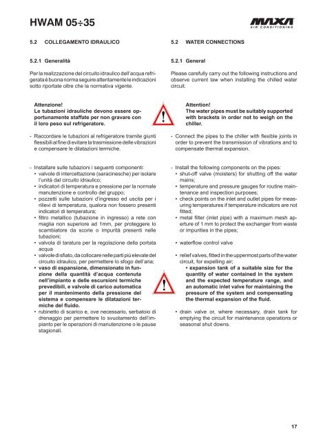
<strong>HWAM</strong> 05÷355.2 collegamento idraulico5.2 WATER CONNECTIONS5.2.1 GeneralitàPer la realizzazione del circuito idraulico dell’acqua refrigerataè buona norma seguire attentamente le indicazionisotto riportate oltre che la normativa vigente.5.2.1 GeneralPlease carefully carry out the following instructions andobserve current law when installing the chilled watercircuit.Attenzione!Le tubazioni idrauliche devono essere opportunamentestaffate per non gravare conil loro peso sul refrigeratore.- Raccordare le tubazioni al refrigeratore tramite giuntiflessibili al fine di evitare la trasmissione delle vibrazionie compensare le dilatazioni termiche.Attention!The water pipes must be suitably supportedwith brackets in order not to weigh on thechiller.- Connect the pipes to the chiller with flexible joints inorder to prevent the transmission of vibrations and tocompensate thermal expansion.- Installare sulle tubazioni i seguenti componenti:• valvole di intercettazione (saracinesche) per isolarel’unità dal circuito idraulico;• indicatori di temperatura e pressione per la normalemanutenzione e controllo del gruppo;• pozzetti sulle tubazioni d’ingresso ed uscita per irilievi di temperatura, qualora non fossero presentiindicatori di temperatura;• filtro metallico (tubazione in ingresso) a rete conmaglia non superiore ad 1mm, per proteggere loscambiatore da scorie o impurità presenti nelletubazioni;• valvola di taratura per la regolazione della portataacqua• valvole di sfiato, da collocare nelle parti più elevate delcircuito idraulico, per permettere lo sfogo dell’aria;• vaso di espansione, dimensionato in funzionedella quantità d’acqua contenutanell’impianto e delle escursioni termicheprevedibili, e valvole di carico automaticaper il mantenimento della pressione delsistema e compensare le dilatazioni termichedel fluido.• rubinetto di scarico e, ove necessario, serbatoio didrenaggio per permettere lo svuotamento dell’impiantoper le operazioni di manutenzione o le pausestagionali.- Install the following components on the pipes:• shut-off valve (moisters) for shutting off the watermains;• temperature and pressure gauges for routine maintenanceand inspection purposes;• check points on the inlet and outlet pipes for measuringtemperatures if temperature indicators are notfitted;• metal filter (inlet pipe) with a maximum mesh apertureof 1 mm to protect the exchanger from wasteor impurities in the pipes;• waterflow control valve• relief valves, fitted in the uppermost parts of the watercircuit, for expelling air;• expansion tank of a suitable size for thequantity of water contained in the systemand the expected temperature range, andan automatic inlet valve for maintaining thepressure of the system and compensatingthe thermal expansion of the fluid.• drain valve or, where necessary, drain tank foremptying the circuit for maintenance operations orseasonal shut downs.17