standard series zb1.25
standard series zb1.25
standard series zb1.25

You also want an ePaper? Increase the reach of your titles
YUMPU automatically turns print PDFs into web optimized ePapers that Google loves.
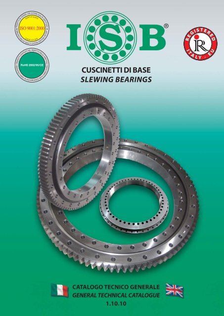
CUSCINETTI DI BASESLEWING BEARINGSCATALOGO TECNICO GENERALEGENERAL TECHNICAL CATALOGUE1.10.10
SEDE PRINCIPALEHEAD OFFICEMAGAZZINOWAREHOUSEUFFICIO COMMERCIALESALES DEPARTMENTITALCUSCINETTIforniture industrialiindustrial suppliesSHANGHAI ITALCUSCINETTI CO., LTD.S.p.A.ITALCUSCINETTI S.p.A. - Via Caponnetto, 15 - 42048 RUBIERA (Reggio Emilia) ITALIAVendite ITALIA Tel. 0039 0522 621811 - Fax 0039 0522 628926 - comm.it@italcuscinetti.itExport sales dept. Tel. 0039 0522 621830 - Fax 0039 0522 626149 - export@italcuscinetti.itImport dept. Tel. 0039 0522 621880 - Fax 0039 0522 629255 - import@italcuscinetti.itinfo@italcuscinetti.it - www.italcuscinetti.itSHANGHAI ITALCUSCINETTICO., LTD. - No. 89, Lane 85 Qianyun RoadXujing Town, Qingpu District - Shanghai 201702 (People’s Republic of China)Tel. 0086 21 34313431 - Fax 0086 21 34314431DISTRIBUTORE ESCLUSIVISTA PER L’EUROPA - EUROPEAN SOLE AGENT*SKFFAGCUSCINETTI E COMPONENTICUSCINETTI PER APPLICAZIONI “BASSA RUMOROSITÀ”CUSCINETTI A RULLINI - RUOTE LIBERECOMPONENTI PER LA MOVIMENTAZIONE LINEARESUPPORTI AUTOALLINEANTICUSCINETTIBEARINGS AND COMPONENTS *BEARINGS FOR “LOW NOISE” APPLICATIONS *NEEDLE BEARINGS - FREE WHEELS *COMPONENTS FOR LINEAR MOTION *SELF-ALIGNING BEARING UNITS *BEARINGS
Programma generale di vendita • General sales programITALY/EU REGISTEREDITALY/EU REGISTEREDCUSCINETTI E COMPONENTI *BEARINGS AND COMPONENTS *BOCCOLE *BUSHES *ITALY/EU REGISTEREDITALY/EU REGISTEREDSFERE PORTANTI - SFERE DI PRECISIONE - RULLI E RULLINI DI PRECISIONEBALL TRANSFER UNITS - PRECISION BALLS - PRECISION ROLLERS AND NEEDLESSUPPORTI AUTOALLINEANTI *SELF-ALIGNING BEARING UNITS *ITALY/EU REGISTEREDITALY/EU REGISTEREDSNODI SFERICI - TESTE A SNODO - FORCELLE *SPHERICAL PLAIN BEARINGS - ROD ENDS - CLEVISES *CUSCINETTI PER APPLICAZIONI “BASSA RUMOROSITÀ” *BEARINGS FOR “LOW NOISE” APPLICATIONS *ITALY/EU REGISTEREDITALY/EU REGISTEREDCUSCINETTI A RULLINI *NEEDLE BEARINGS *COMPONENTI PER LA MOVIMENTAZIONE LINEARE *COMPONENTS FOR LINEAR MOTION *ITALY/EU REGISTEREDDisponibile grande assortimento completocon pronta consegna.Big and full assortment with promptdelivery.SUPPORTI AUTOALLINEANTISELF-ALIGNING BEARING UNITSCUSCINETTI SKF - FAGSKF - FAG BEARINGS* Per ulteriori informazioni, potete richiedere il catalogo tecnico,disponibile anche on line: www.italcuscinetti.it* For further information, please ask for technical catalogue, alsoavailable on line: www.italcuscinetti.it
CATALOGO TECNICO GENERALEGENERAL TECHNICAL CATALOGUEDistributore / Distributor
PAESI DOVE SIAMO PRESENTICOUNTRIES WHERE WE ARE REPRESENTED629315030 516144 64232218343646 2564952 5424 65560 71 5557 1733 378286968564140167395912 353227192214753201613725815437048736310*ora legale (periodo da marzo ad ottobre in Italia) ora solare (-1) per le capitali con l’orario indicato in rosso non c’è ora legale*summer time (from march to october in Italy) <strong>standard</strong> time (-1) time is indicated in red for Capitals without summer time
PRODUZIONETutti i prodotti ISB® sono costruiti esclusivamenteda aziende con Sistema Qualità certificato secondole norme UNI EN ISO 9001:2000.PRODUCTIONAll products ISB® are manufactured exclusively bycompanies with UNI EN ISO 9001:2000 certifiedQuality System.
PRODUZIONETutti i prodotti ISB® sono costruiti esclusivamenteda aziende con Sistema Qualità certificato secondole norme UNI EN ISO 9001:2000.PRODUCTIONAll products ISB® are manufactured exclusively bycompanies with UNI EN ISO 9001:2000 certifiedQuality System.
CONTROLLO QUALITÀ ITALIAITALY QUALITY CONTROL... centro di controllo per la qualità nella nostra sedein ITALIA.… uno staff di Ingegneri tecnici della Qualità, alvostro servizio.... a quality control centre is located in our ITALYheadquarters.… our staff of technical engineers at yr service, forQuality.CONTROLLO QUALITÀ ASIAASIA QUALITY CONTROL... un’ulteriore serie di controlli vengono eseguitida Laboratori esterni specializzati, attrezzati conmoderni strumenti.Laboratorio Controllo Qualità.... an additional <strong>series</strong> of tests are conducted byspecialised third party Laboratories using the latestinstrumentsQuality Control Laboratory.
DOCUMENTAZIONE QUALITÀQUALITY DOCUMENTATIONS
GAMMA PRODOTTI ISB®PRODUCTS RANGE ISB®CUSCINETTI - COMPONENTI - BOCCOLE - SFERE PORTANTISFERE DI PRECISIONE - RULLI E RULLINI DI PRECISIONEBEARINGS - COMPONENTS - BUSHES - BALL TRANSFER UNITSPRECISION BALLS - PRECISION ROLLERS AND NEEDLESLa gamma prodotti ISB® è incontinuo sviluppo, a breve è previstol’ampliamento con ulteriori prodotti.The ISB® range is continuously inevolution and shortly will be widenedby the addition of new items.SUPPORTI AUTOALLINEANTI - SNODI SFERICI - TESTE A SNODO - FORCELLESELF-ALIGNING BEARING UNITS - SPHERICAL PLAIN BEARINGS - ROD ENDS - CLEVISES
INDICE - INDEXINDICEINDEXPARTE 1APPLICAZIONI E TECNOLOGIADEI CUSCINETTI DI BASE pag. 13SETTORI DI APPLICAZIONE » 14COMPONENTI DEL CUSCINETTODIBASE » 23MATERIALI PER GLI ANELLI » 26TEMPRAAD INDUZIONE DELLE PISTE » 28TEMPRAAD INDUZIONE DEI DENTI » 29TIPOLOGIA DI GIOCHI » 30SISTEMI DI PROTEZIONE SUPERFICIALE » 32PART 1APPLICATIONS & TECNOLOGYOF SLEWING BEARINGS pag. 13APPLICAZION FIELDS » 14SLEWING BEARING COMPONENTS » 23RINGS MATERIAL » 26RACEWAY INDUCTION HARDENING » 28GEAR INDUCTION HARDENING » 29CLEREANCES TYPES » 30SURFACE PROTECTION SYSTEMS » 32PARTE 2SCELTA DEL CUSCINETTO DI BASE » 35INTRODUZIONE » 36CAPACITÀ STATICA » 37FATTORE DI SICUREZZASTATICO » 41RESISTENZA DEI BULLONI DI FISSAGGIO » 42UTILIZZO DEL DIAGRAMMA DI CARICO » 44VERIFICA IN PRESENZA DI CARICO RADIALE » 46CALCOLO DELLA VITAAFATICA » 47RESISTENZA DELLA DENTATURA » 49ATTRITO E LUBRIFICAZIONE » 51PART 2SLEWING BEARING SELECTION » 35INTRODUCTION » 36STATIC CAPACITY » 37STATIC SAFETY FACTOR » 41BOLTS RESISTANCE » 42USE OFLOAD DIAGRAM » 44VERIFICATION IN PRESENCE OFRADIAL LOAD » 46RATING LIFE CALCULATION » 47GEAR RESISTANCE » 49FRICTION & LUBRICATION » 51PARTE 3CATALOGO GENERALEDEI CUSCINETTI DI BASE » 53OVERVIEW » 54CODIFICA » 56SERIE LEGGERA » 57DENTATA INTERNANON DENTATASERIE FLANGIATA, UN GIRO DI SFERE » 59DENTATA ESTERNADENTATA INTERNANON DENTATAPART 3GENERAL CATALOGUEOF SLEWING BEARINGS » 53OVERVIEW » 54DESIGNATION » 56LIGHT SERIES » 57INTERNAL TOOTHEDUNTOOTHEDFLANGED SERIES , ONE ROW OF BALLS » 59EXTERNAL TOOTHEDINTERNAL TOOTHEDUNTOOTHED11
INDICE - INDEXSERIE A UN GIRO DI SFERE4 PUNTI DI CONTATTO pag. 77DENTATA ESTERNADENTATA INTERNANON DENTATASERIE A DUE GIRI DI SFERE8 PUNTI DI CONTATTO » 101DENTATA ESTERNADENTATA INTERNANON DENTATASERIE A UN GIRODI RULLI INCROCIATI » 109DENTATA ESTERNADENTATA INTERNANON DENTATASERIE A TRE GIRI DI RULLI » 125DENTATA ESTERNADENTATA INTERNASERIE PER TAVOLE GIREVOLI » 133YRT, YRTS, ZKLDF4 POINT CONTACTONE ROW OF BALLS SERIES pag. 77EXTERNAL TOOTHEDINTERNAL TOOTHEDUNTOOTHED8 POINT CONTACTDOUBLE ROWOFBALLS SERIES » 101EXTERNAL TOOTHEDINTERNAL TOOTHEDUNTOOTHEDONE ROWCROSSED ROLLERSSERIES » 109EXTERNAL TOOTHEDINTERNAL TOOTHEDUNTOOTHEDTRIPLE ROWROLLER SERIES » 125EXTERNAL TOOTHEDINTERNAL TOOTHEDTURNTABLE BEARING SERIES » 133YRT, YRTS, ZKLDFPARTE 4INSTALLAZIONE E MANUTENZIONE » 139CONTROLLO PLANARITÀ » 140SERRAGGIO DELLA BULLONERIA » 141OPERAZIONI PRELIMINARI » 142MONTAGGIO » 143LUBRIFICAZIONE DELLE PISTE » 145LUBRIFICAZIONE DELLA DENTATURA » 146MOVIMENTAZIONE E STOCCAGGIO » 147MODULO DI RICHIESTACLIENTE » 149PART 4INSTALLATION AND MAINTENANCE » 139FLATNESS CHECK » 140BOLTS TIGHTENING » 141PRELIMINARY OPERATIONS » 142INSTALLATION » 143RACEWAY LUBRICATION » 145GEAR LUBRICATION » 146HANDLING AND STORAGE » 147CUSTOMER REQUEST MODULE » 14912
PARTE 1 - APPLICAZIONI E TECNOLOGIA DEI CUSCINETTI DI BASEPART 1 - APPLICATIONS & TECNOLOGY OF SLEW BEARINGS
APPLICAZIONI E TECNOLOGIA - APPLICATIONS & TECNOLOGYSETTORI DI APPLICAZIONE DEI CUSCINETTI DI BASESLEW BEARING APPLICATION FIELDSIl cuscinetto di base (comunemente definito con il nome di ralla) si rende necessario quando, all’interno di un macchinarioo di un impianto, una parte strutturale deve ruotare rispetto ad un’altra secondo un asse univoco, assicurando il vincolotra le parti.II cuscinetto di base, con Ia massima rigidità possibile offerta del suo disegno, deve sopportare e trasmettere i carichi operatividella struttura a cui è collegato e deve inoltre garantire il grado di precisione richiesto dall’applicazione, il rispetto deiparametri di funzionamento e il ciclo di vita richiesto. È evidente come il cuscinetto sia un componente fondamentale e lasua scelta deve rispondere ad attenti studi tecnici. Italcuscinetti SpA è a disposizione per assistervi nella scelta del cuscinettoideale per la vostra applicazione.The slewing bearing has to be adopted when, in a machinery or in mechanical plant, a structural part must rotate opposed toanother part, along a fixed axis, ensuring the axial and radial link between the two parts. The slew bearing, with the maximumstiffness offered by its design, must bear and transmit the operative loads of the structure it is linked to, and also it must guaranteethe required motion precision, the respect of operational parameters, and the required lifetime.It is evident how the slewing bearing is a fundamental component and its choice must be done according to specific technicalstudies. Italcuscinetti SPA can assist your Company in the choice of the suitable bearing.Le applicazioni più comuni sono:• escavatori• pompe per calcestruzzo• betoniere• veicoli sollevatori• autogru• gru edili e portuali• compattatori• turbine eoliche• radar• manipolatori, posizionatori• caroselli di imbottigliamento e trasporto• tavole girevoliCommon application are:• excavators• concrete pumps• concrete trucks• boomlift, manlift• crane truck• civil and harbour crane• compactors• wind turbines• radar• manipulators• filling carousels• rotary tablesRadarManipolatore / Manipulator14
APPLICAZIONI E TECNOLOGIA - APPLICATIONS & TECNOLOGYBetoniere / Concrete trucksMacchine per il legnameForest machinesGru edili / Civil cranes15
APPLICAZIONI E TECNOLOGIA - APPLICATIONS & TECNOLOGYESCAVATORI / EXCAVATORSIn questa applicazione, per la tipologia di carichi trasmessi in fase operativa, la ralla deve avere elevate caratteristiche dirigidità, per contrastare le repentine variazioni di carico, buone capacità rotazionali, per permettere un agevole rotazionedella sovrastruttura, resistenza a urti su pista di rotolamento e dentatura. La scelta del cuscinetto di base ISB idoneo sonovalori aggiunti alla qualità generale del vostro progetto.In this type of application, according to the typology of load and environmental conditions, the slew bearing must have highstiffness features, for counteracting fast load variations, good rotational features, for easy rotation of the superstructure, resistanceto impact stresses in raceways and gear, in order to preserve its lifetime. The correct choice of suitable ISB slew bearings is an addedvalue to the general quality of your project.REFERENCE SERIESE/Z R1 <strong>series</strong>One row crossed roller bearingE/Z B1 <strong>series</strong>One row 4 contact point ball bearing16
APPLICAZIONI E TECNOLOGIA - APPLICATIONS & TECNOLOGYPOMPE PER CALCESTRUZZO / CONCRETE PUMPSIl cuscinetto di base nelle pompe da calcestruzzo sorregge l’elongazione del braccio, consentendone la rotazione, e pertantoè soggetto ad un forte momento ribaltante. Deve anche possedere una struttura compatta per poter essere montato suiveicoli stradali. La sua scelta ricade solitamente su cuscinetti a due giri di sfere a otto punto di contatto, altrimenti puòricadere sul singolo giro di sfere, dove le sollecitazioni lo consentono.The slew bearing in concrete pumps supports the boom elongation also allowing its rotation, and for this reason it is subject to ahuge tilting moment. It must also have a compact structure in order to be mounted on road vehicles. A common choice is a doublerow ball bearings, 8‐contact points, otherwise if loads are much lower, it could be one‐row ball bearing.REFERENCE SERIESE/Z B1 <strong>series</strong>4 contact point one row ball bearingE/Z B2 <strong>series</strong>8-point contact double row ball bearing17
APPLICAZIONI E TECNOLOGIA - APPLICATIONS & TECNOLOGYCAROSELLI DI IMBOTTIGLIAMENTO - FILLING CAROUSELSNei caroselli di imbottigliamento il cuscinetto di base può variare dal piccolo al grande diametro, ma le caratteristichefondamentali devono essere l’elevata precisione costruttiva unita all’elevata velocità di rotazione che essi devono garantirein modo continuativo.In filling carousels, slew bearing dimensions could vary from small to large diameter, but common characteristics are high precisionconstruction and high continuous rotational speed.REFERENCE SERIESEB1 <strong>series</strong>One row 4 contact point ball bearingEBL <strong>series</strong>One row 4 contact point ball bearing -Flanged <strong>series</strong>COMPATTATORI - COMPACTORSNei compattatori, vista la bassa velocità di rotazione del rullo e l’elevato grado di sollecitazione in presenza di vibrazioni,l’utilizzo di due cuscinetti di base che sostengono il rullo è la soluzione ideale.In compactor rollers, due to low rotation speed of the roller and to the relevant stress condition in presence of vibrations, the useof a pair of slew bearings supporting the roller is an ideal solution.REFERENCE SERIESNB1 <strong>series</strong>One row 4 contact pointball bearing, untoothed18
APPLICAZIONI E TECNOLOGIA - APPLICATIONS & TECNOLOGYVEICOLI SOLLEVATORI - BOOMLIFT, MANLIFTApplicazione tipica del cuscinetto di base. La ralla sostiene tutto il carico a sbalzo della piattaforma aerea.This is a typical application of the slewing bearing. The whole overhang load of the aerial platform is entirely supported by thebearing.REFERENCE SERIESEB1/ZB1 <strong>series</strong>One row 4 contact point ballbearingEB2/ZB2 <strong>series</strong>Double row 8 contact pointball bearingPINZE DI SOLLEVAMENTO ROTANTI - ROTATING CLAMPSui muletti è spesso necessario avere delle pinze di sollevamento in grado di ruotare l’oggetto sollevato, per scopi come ilversamento del suo contenuto o per permettere la sua movimentazione all’interno dei cicli di produzione e di stoccaggio.On the forklifts it is often necessary to have a lifting clampable to rotate the lifted object, with the possibility to pourits content or else to allow its handling in the productionand storage cycles.REFERENCE SERIESEB1 <strong>series</strong>One row 4 contact point ballbearing, external toothed19
APPLICAZIONI E TECNOLOGIA - APPLICATIONS & TECNOLOGYROBOT DI SALDATURA - WELDING ROBOTSUn cuscinetto viene montato alla base del braccio dei robot di saldatura per sorreggere la struttura a sbalzo e consentirnel’azione rotativa; in aggiunta è richiesta una elevata rigidità per assicurare la necessaria precisione sul posizionamento.A slew bearing is applied to the base of the arm of welding robots, in order to support the overhang structure and allow its rotationalmotion; moreover, high stiffness is required in order to ensure precision in positioning.REFERENCE SERIESZR1/ER1One row crossed roller bearing,internal or external toothedTAVOLE GIREVOLI - ROTARY TABLESSu macchine utensili, dove è necessario un controllo micrometrico sulla posizione del pezzo, alla base della tavole girevoleviene montato un cuscinetto YRT. Questo cuscinetto risponde ai massimi requisiti di precisione, costruiti senza gioco ecompletamente rettificati, internamente ed esternamente. La fornitura <strong>standard</strong> è completa di certificati di controllodimensionali.In machining centers, where a micrometric control of piece positioning is required, a YRT type bearing is installed on the turntablebase. YRT is produced according to the highest precision requirements, completely grinded internally and externally, and assembledwithout any radial and axial clearance. The <strong>standard</strong> supply of this product also provides dimensional check certificates.REFERENCE SERIESYRT <strong>series</strong>Standard rotary table bearings.YRTS <strong>series</strong>Adding high speed, low frictional torque20
APPLICAZIONI E TECNOLOGIA - APPLICATIONS & TECNOLOGYGRU PORTUALI E NAVALI - HARBOUR & DECK CRANESLe gru portuali e navali rappresentano uno dei campi fondamentali per l’impiego dei cuscinetti di base: il loro impiego èimprescindibile per supportare la struttura soggetta a gravose condizioni di carico, caratteristiche nella movimentazionedei materiali dei container. Italcuscinetti SpA è in grado di eseguire uno studio tecnico di progettazione o verifica delcuscinetto in tutte le sue parti, e inoltre di fornire tutti i certificati di conformità/materiali che accompagnano questo tipo diforniture.Harbour and deck cranes represent one of the most important application field for slew bearings: their use is fundamental tosupport the structure subject to extreme load conditions, such as the handling of containers. Italcuscinetti SPA is able to design orto verify the suitable slew bearing in each part it is composed, and also to provide the compliance/material certificate usuallyrequired in this type of supply.REFERENCE SERIESER3 & ZR3 <strong>series</strong>Triple-row crossed roller bearingER1 & ZR1<strong>series</strong>One-row crossed roller bearing21
APPLICAZIONI E TECNOLOGIA - APPLICATIONS & TECNOLOGYTURBINE EOLICHE - WIND TURBINESIn questo tipo di applicazione i cuscinetti di base sono componenti funzionali fondamentali e il loro design varia in base allafunzione svolta sulla torre eolica. Il primo tipo di cuscinetto si chiama Blade Bearing “B” ed è fissato alla base di ogni pala ene consente l’orientamento. Il secondo tipo si chiama Yaw Bearing “Y” ed è fissato alla base della navicella consentendol’orientamento dell’intera turbina. Il terzo tipo si chiama Main Bearing “M” e consente il trasferimento del moto rotatoriodalla turbina all’alternatore.For this type of application the slew bearings are extremely important functional component and their design changes accordingto their position in the wind turbine. The first type is called Blade Bearing ”B”, it is fixed in the base of each blade allowing itsorientation. The second type is the Yaw Bearing ”Y”, it is fixed on the base of the nacelle and it allows the orientation of the wholeturbine. The third type is called Main Bearing “M” and it allows the motion transfer from the turbine to the generator.MYBTurbina eolica (off shore)22
APPLICAZIONI E TECNOLOGIA - APPLICATIONS & TECNOLOGYCOMPONENTI DEL CUSCINETTO DI BASE - SLEW BEARINGS COMPONENTSIl cuscinetto di base è costituito normalmente da due anelli di acciaio ad alta resistenza il cui movimento rotatorio relativoviene permesso tramite la creazione di piste di rotolamento ospitanti gli elementi volventi, che possono essere sfere o rullicilindrici. Le piste di rotolamento sono il cuore della struttura del cuscinetto e su di esse si rivolge la maggiore attenzionedurante il ciclo di produzione. Esse dovranno essere trattate termicamente per aumentarne la durezza, non solo in superficie,ma anche in profondità e permettere al cuscinetto di sopportare i gravosi carichi a cui è normalmente soggetto conferendogliintegrità nel tempo.The slew bearing is normally composed of two rings made of high resistance steel, and their relative rotating motion is allowed bythe creation of raceways hosting the rolling elements, which can be balls or cylindrical rollers. The roller raceways are the structuralheart of the bearing and require the major attention during the production cycle. An induction hardening treatment must beapplied on raceways in order to increase their hardness both on the surface and in depth. This allows the bearing to endure thehuge loads it is usually subject to, ensuring structural integrity over time.EBL <strong>series</strong>One row 4 contact point ballFlanged bearing23
APPLICAZIONI E TECNOLOGIA - APPLICATIONS & TECNOLOGYComponenti <strong>standard</strong> di un cuscinetto di baseStandard components of a slewing bearingMarcatura soft spotSoft spot markingAnello esternoOuter ringForatura difissaggio esternaOuter fixing holesGuarnizione superiorein NBRNBR upper sealingForatura difissaggio internaInner fixing holesTappo (P)Filling PlugIngrassatore (G)GreaserTarghetta diidentificazione ISBISB identification plateDentaturaGearPista di rotolamentoRoller’s racewayGuarnizione inferiore in NBRNBR lower sealingDistanziale in NylonNylon SpacerElemento volventeRoller elementElementi volventiRolling elementsSfere DIN 5401 vengono usate per cuscinetti a quattro punti di contatto mentre rulli cilindrici DIN 5402 per cuscinetti a rulli:entrambi i componenti sono prodotti con materiale 100 Cr6.La dimensione delle sfere o dei rulli può essere facilmente rintracciabile nella sigla stessa del cuscinetto (vedi pag. 56).DIN5401 balls are used for four point contact bearings while DIN5402 cylindrical rollers are used for crossed roller bearings: bothtypes of rolling elements are made of 100 Cr6 material.Rolling element diameter can be taken from the code of the slew bearing as per the designation (see pag. 56).24
APPLICAZIONI E TECNOLOGIA - APPLICATIONS & TECNOLOGYDistanzialiSpacersDistanziali in Nylon vengono usati per mantenere i componenti per la rotazione (sfere, rulli) separati tra loro evitandonequalsiasi contatto.Nylon spacers are used to guide the rolling elements, to hold them at an equal distance from each other and to prevent them fromcoming into contact with each other.GuarnizioniSealingII materiale utilizzato per la guarnizione è gomma NBR. La guarnizione chiude il vuoto che si crea tra un anello e I’altroevitando l'ingresso di sporcizia, polvere e umidità. Una corretta lubrificazione incrementa I'efficacia della guarnizione (vediLubrificazione delle piste pag. 145)Seals made from NBR rubber protect the gap in the bearing on both sides from the ingress of dirt, dust and moisture. Please notethat a correct lubrication increases the effectiveness of the seals (see Raceway Lubrication page 145)GrassoGreaseI nostri cuscinetti vengono forniti con una iniziale lubrificazione di piste e dentatura con grassi specifici elencati nelle sezioneLubrificazione, parte 4 Installazione e Manutenzione. Seguire attentamente le istruzioni fornite per preservare la vita delcuscinetto.Our bearings are delivered with an initial lubrication of raceways and gear, using grease listed in the lubrication section , part 4Installation and Maintenance. Strictly follow the instructions supplied in order to preserve the lifecycle of the bearing.IngrassatoriGreasersSono posti sul diametro dell'anello senza dentatura (per i cuscinetti senza dentatura sono posti sull’anello esterno) e servonoper ingrassare la sede di rotolamento degli elementi volventi.They are located on the diameter of the ungeared ring (for the bearings without gear teeth they are located on the outer ring) andthey are used to grease the raceway.25
APPLICAZIONI E TECNOLOGIA - APPLICATIONS & TECNOLOGYMATERIALI PER GLI ANELLI - RINGS MATERIALI materiali con cui si costruiscono le ralle possono essere acciai al carbonio, come il C45, oppure acciai legati come il 42CrMo4.L’utilizzo di uno o l’altro materiale è essenzialmente legato alle caratteristiche meccaniche richieste, fra cui tenacità e durezza,ma anche a fattori tecnologici. Il 42CrMo4 offre la possibilità di ottenere una maggiore profondità dello strato tempratodelle piste di rotolamento e quindi capacità di carico maggiori. Il C45 (o equivalente) è il materiale con cui vengono costruitila maggior parte dei cuscinetti <strong>standard</strong> di medio basso diametro, il 42CrMo4 viene utilizzato per diametri medi-grandi eper molteplici costruzioni speciali.The materials used to produce slew bearings can be carbon steel, as C45, or alloy steel, as 42CrMo4. The choice between these twotypes of steel is related to the required mechanical performances, like core‐tenacity and hardness, but also to other technologicalfactors, as hardenability. The 42CrMo4 allows a deeper thickness of the hardened layer than C45, ensuring higher load capacity.The C45 (or equivalent) is the material used for the production of the major part of <strong>standard</strong> medium- low diameter bearing, the42CrMo4 is used for medium‐high diameters, and for many different special applications.Acciai alcarbonioAcciaiolegatoUNI DIN EURO NORM AISI -SAE GB BS 970 JISItalia Germania Europa USA Cina Inghilterra GiapponeItaly Germany Europe China England JapanC45 C45, CK45 C45 1045 C45, 50Mn EN8D42CrMo4 42CrMo4 42CrMo4 4140 42CrMo En19AS45CS48CSCM440Tabella 1 - corrispondenza nelle varie unificazioni delle denominazioni degli acciai per cuscinetti di baseForm 1 - correspondance of steel used for slewing bearing production, in various normative26
APPLICAZIONI E TECNOLOGIA - APPLICATIONS & TECNOLOGYDopo forgiatura e laminazione, un trattamento termico, che può essere di bonifica o di normalizzazione, viene effettuatoper incrementare tutte le caratteristiche meccaniche del materiale fra cui resistenza a trazione, tenacità, durezza, temprabilità.Il ciclo di bonifica, che prevede la successione di un trattamento di tempra più uno di rinvenimento, conferisce al materialeuna durezza e una resistenza a cuore maggiore di quella della normalizzazione, caratteristiche necessarie per dentaturesoggette alle massime sollecitazioni meccaniche e ambientali.After forging and ring mill, a heat treatment, either core‐hardening or normalization, must be applied in order to increase allmechanical proprieties of the material, such as tensile strength, tenacity, hardness. The core-hardening process, composed by asuccession of quenching and tempering heat treatments, confers to the material higher hardness and higher core-resistance valuesthan normalization, proprieties required in case of heavy stress conditions on the gear.27
APPLICAZIONI E TECNOLOGIA - APPLICATIONS & TECNOLOGYTEMPRA AD INDUZIONE DELLE PISTE - INDUCTION HARDENING OF RACEWAYSIl trattamento di tempra delle piste di rotolamento, innalzando il loro valore di durezza in superficie e in profondità finoad un valore compreso fra 55 e 62 HRC, serve ad aumentare la capacità di carico del cuscinetto e a preservare le pisteda fenomeni di plasticizzazione dovuto alle pressioni di contatto con gli elementi volventi. Questo trattamento consistenell’avvicinare alla pista un induttore di rame percorso da corrente alternata di forte amperaggio. La vicinanza del campomagnetico variabile alla pista metallica induce correnti parassite locali che per effetto joule riscaldano immediatamentela zona interessata oltre la temperatura di austenizzazione, che viene quindi raffreddata in uscita per permettere laformazione di martensite e carburi. La scelta di un acciaio al carbonio come il C45 o legato come il 42CrMo4 è legataproprio all’ottenimento dei migliori risultati metallurgici durante questo procedimento.The heat treatment of rollerways, increasing the hardness value on surface and in depth up to a value range of 55 ÷ 62 HRC,involves a higher load capacity of the bearing and avoid plastic deformation along rollers contact points. This heat treatmentconsists in bringing a copper made inductor crossed by high amperage alternate current nearer to the rollerways. The proximityof magnetic field to the metallic rollerway inducts parasite currents and Joule effect that produces an instantaneous heatingof interested regions leading to the austenite temperature field. The following quick cooling produces the formation ofmartensite and carbides.The choice of a carbon steel, as C45, as well as an alloy steel, as 42CrMo4, allows to obtaining best metallurgical results duringthis process.Soft spot “S”Il soft spot (punto morbido) è un punto delle piste di ambeduegli anelli che non è temprato ad induzione in quanto altermine del processo di tempra non é possibile sovrapporregli stacchi di tempra, rischio cricca o addirittura rottura delpezzo. Per l’anello non dentato è buona norma far coincidereil soft spot con il punto di inserimento delle sfere, ovvero conil tappo, che viene lavorato insieme alla pista.Per l’anello dentato si rende invece necessaria l’indicazionecon una lettera “S” stampigliata sulla faccia superioredell’anello, in corrispondenza del soft spot.The soft spot is a raceway point that has not been induction hardened, due the fact at the end of hardening process it isn’tpossible to overlay the hardening ends, the risk is to generate cracks or directly to produce the breaking of the piece. For theuntoothed ring is a common rule to make the soft spot coincident with the filling plug, the inserting point of roller elements,machined together to the raceways. In order to identify the soft spot on the geared ring it is necessary to stamp a “S” letter onthe upper surface of the bearing, in corresponding position.28
APPLICAZIONI E TECNOLOGIA - APPLICATIONS & TECNOLOGYTEMPRA AD INDUZIONE DEI DENTI - INDUCTION HARDENING OF THE GEARLa durezza superficiale <strong>standard</strong> del materiale bonificato utilizzato arriva ad un massimo di 30 HRC (42CrMo4). Questovalore di durezza non sempre può essere accettabile per preservare la vita della dentatura in alcune applicazioni. Unacoppia di rotazione elevata che produce un elevato sforzo (e attrito) sul dente, alte velocità di rotazione, condizioniambientali sfavorevoli con presenza di polvere o elementi abrasivi, oppure la necessità di portare il ciclo di vita dellaralla al suo massimo ottenibile, fa si che il trattamento di tempra ad induzione venga effettuato anche sulla dentatura.Il trattamento può essere solo sul fianco oppure su fianco e fondo del dente, a seconda dei carichi e del tipo diapplicazione, e porta il valore di durezza superficiale fino ad un massimo di circa 60 HRC.The <strong>standard</strong> surface hardness of core‐hardened steel used for bearing could be 30 HRC at maximum (42CrMo4). This valueof hardness could not be enough to preserve the lifetime of the gear in some applications. A high rotational torque producinga high load (and friction) on the tooth, high rotational speed, heavy duty environmental condition including dust and abrasiveelements, or the necessity to extend the lifecycle of the bearing to the maximum, any of those aspects may require a gearinduction hardening. The heat treatment could be only flank or flank & root of the teeth, according to loads and applicationtype, and it leads the surface hardness value to a maximum value of about 60 HRC.Tempra del dente fianco e fondoGear hardening flank and root of the teeth29
APPLICAZIONI E TECNOLOGIA - APPLICATIONS & TECNOLOGYTIPOLOGIE DI GIOCHI - CLEARANCE TYPEIl gioco di una ralla è la misura del movimento libero dell’anello esterno rispetto a quello interno (e viceversa), valutato indue direzioni: in senso assiale, cioè nella direzione definita dall’asse di rotazione, e radiale, ovvero in qualsiasi direzioneperpendicolare all’asse stesso. Il gioco ralla è determinato dall’accoppiamento degli elementi volventi con le piste dirotolamento degli anelli componenti, ciascuno con la sua tolleranza. Il cuscinetto di base si può presentare con quattrotipologie di giochi differenti, siano gli elementi volventi sfere oppure rulli. La scelta dei giochi viene fattacontemporaneamente alla scelta del tipo di ralla e dipende dal campo di applicazione della ralla stessa.Clearance of a slew bearing is the measure of the motion freedom of the outer ring compared to the inner ring (and vice versa),evaluated in two directions: along the axial direction, defined by the revolution axis of the bearing, and along radial direction, anydirection perpendicular to the first one When assembling, the plays of the bearing is determined by matching rings raceways withrollers, each component having its tolerance. The slew bearing can show four different types of clearances, both ball and crossedroller bearing. The type choice id done simultaneously to bearing type selection, and mainly depends on the application field.Gioco radiale Radial clearance ∂ rGioco assiale Axial clearance ∂ aFISSO/FIXEDRaffigurazione del gioco ralla assiale e radialeSlew bearing axial and radial clearance representationDi seguito la descrizione dei vari casi in modo tale che possiate prevedere la scelta migliore per la vostra applicazione.È comunque sempre disponibile la consulenza dell’ufficio Tecnico ISB.On the following page you can find the description of the different cases so that you can make the best choice for your application.ISB technical center is always available to support you.30
APPLICAZIONI E TECNOLOGIA - APPLICATIONS & TECNOLOGYGiochi <strong>standard</strong> / Standard Clearance ∂ a , ∂ r0,10 ÷ 0,35 mmCatalogue StandardSeriesCatalogue PrecisionSeriesSpecial designNormalmente in una ralla sono previsti giochi <strong>standard</strong> assiali e radiali che possonovariare, a seconda della tipologia di ralla, da 1 a 4 decimi di millimetro. La presenza deicentraggi sugli anelli è funzione dell’applicazione e/o del tipo di ralla: sulle serie <strong>standard</strong>a sfere, ad esempio, i centraggi sono opzionali, sulle rulli invece sono nello <strong>standard</strong>.Usually in a slew bearings axial and radial clearance can vary from 0,1 to 0,4 mm. Pilots arefunction of application and/or type of bearings: on <strong>standard</strong> balls <strong>series</strong>, for example, pilotsare optional, in <strong>standard</strong> roller <strong>series</strong> pilots are for <strong>standard</strong> construction.Giochi ridotti / Reduced ClearanceQuando l’applicazione richiede la massima precisione durante la fase operativa, con -servando comunque una elevata velocità di rotazione, il disegno della ralla cambia infavore di una riduzione del gioco assiale e radiale. I giochi possono variare dal valorenullo a pochi centesimi in valore positivo. Le serie di precisione adottano le dimensionigenerali delle serie <strong>standard</strong> e presentano centraggi centesimali su ambedue gli anelli.When the application requires the maximum precision during operation, with high valuesof rotational speed, the slew bearing design changes in favor of a reduction of axial and radialplays. Clearance can vary from null value to few hundreds of millimeter, in positive value.Precision <strong>series</strong> adopt general dimensions of <strong>standard</strong> <strong>series</strong> and show pilots on both rings.Leggero precarico / Slight preload∂ a , ∂ r∂ a , ∂ r0 ÷ 0,10 mm0 ÷ – 0,03 mmQuando l’applicazione richiede l’assenza di giochi sia radiale e assiale, allo scopo adesempio di annullare qualsiasi incertezza sul posizionamento oppure perché la rallalavora in posizione verticale, il gioco viene annullato e la costruzione viene detta “conprecarico”. Quando è leggero, cioè con interferenze che variano dal valore nullo fino apochi centesimi in valore negativo, la ralla riesce a conservare una adeguata capacitàrotazionale, anche in intensi cicli di funzionamento, con limitate coppie di frizione.Questo tipo di costruzione non è <strong>standard</strong> e deve essere richiesta specificatamente.When the application requires the absence of any plays, radial and axial, in order for exampleto avoid any positional error or because the bearing works in vertical position, the clearanceis eliminated and the construction is called “with preload”. When the condition is slight preloadthe design interference between rollers and raceways can vary from zero to few hundreds ofmillimeter: the slew bearing shows anyway an adequate rotational speed, even on intenseoperational cycles, with a limited friction torque. This type of construction is not <strong>standard</strong>and must be specifically requested.Precarico / Preload∂ a , ∂ r≤ – 0,03 mmSpecial designQuando il tipo di sollecitazione prevede forti momenti ribaltanti che possono invertireimprovvisante direzione e, non trascurando la possibilità che sollecitazioni di tipovibrazionale possono interessare le piste di rotolamento, la costruzione della ralla diventafortemente precaricata. I valori di interferenza sempre negativi sono calcolati in modotale da garantire la funzionalità del cuscinetto e allo stesso tempo rispettando valorilimite di progetto riguardo la coppia di frizione, statica e dinamica. Questo tipo dicostruzione non è <strong>standard</strong> e deve essere richiesta specificatamente.When load conditions includes relevant tilting moments that may quickly invert theirdirection and the eventual presence of vibration which involves rollerways, the slew bearingconstruction must be strongly preloaded. Interference range shows only negative values andits calculation is performed to guarantee the functionality of the bearing and, at the sametime, to observe design limit values of static and dynamic friction torque. This type ofconstruction is not <strong>standard</strong> and must be specifically requested.31
APPLICAZIONI E TECNOLOGIA - APPLICATIONS & TECNOLOGYSISTEMI DI PROTEZIONE SUPERFICIALE - SURFACE PROTECTION SYSTEMIl trattamento di protezione superficiale preserva le superfici metalliche esterne dall’ ossidazione per effetto di agentiatmosferici o chimici, durante l’arco di funzionamento del cuscinetto o semplicemente durante il loro periodo di stoccaggio.Siamo in grado di effettuare i seguenti trattamenti di protezione superficiale, a seconda delle vostre necessità.The external surface protection treatment protects metallic surfaces from their oxidation caused by atmospherical or chemicalagents, during operational lifetime or simply during the storage period.We can apply the following different surface protection treatments, according to your needs.Olio protettivo - Protective OilStandardTutti i cuscinetti di base ISB vengonoprotetti da olio protettivo applicato susuperfici, guarnizioni e dentatura.Consente una protezione costantedurante il trasporto e lo stoccaggio percirca 1 anno.All ISB slew bearings are protected withapplying oil to surfaces, seals and gear.It allows a constant protection for about1 year.Verniciatura - PaintingSu richiesta / On requestSu specifica richiesta del cliente puòessere effettato un trattamento diverniciatura protettiva su superficiesposte.Exposed surfaces can be protectedby painting, on customer request.32
APPLICAZIONI E TECNOLOGIA - APPLICATIONS & TECNOLOGYSISTEMI DI PROTEZIONE SUPERFICIALE - SURFACE PROTECTION SYSTEMZincatura galvanica - Zinc based galvanized coatingSu richiesta / On requestIn caso di agenti atmosferici e chimiciaggressivi può essere applicato un riportochimico a base Ferro-Zinco. Lo strato è dipochi centesimi ma consente unaprotezione resistente con il suo tipicocolore giallo iridescente.In case of atmospheric or chemical agents aFe-Zn galvanized layer can be applied. Thethickness is just few hundreds of mm but itallows a durable protection with its typicaliridescent yellow color.Zincatura spray a caldo - Hot flame spray zinc coatingSu richiesta / On requestZincatura spray a caldo: lo stratoprotettivo e può arrivare fino a qualchedecimo di spessore ed è l’ideale percontrastare qualsiasi tipo di agenteatmosferico essendo resistente anche adazioni di abrasione e urto sulle superfici.This treatment can apply a protective layerup to 3 ten of millimeter thickness. It resiststo any type of atmospheric agent and alsoto abrasive action on surface.33
PARTE 2 - SCELTA DEL CUSCINETTO DI BASEPART 2 - SLEW BEARING SELECTION
SCELTA DEL CUSCINETTO DI BASE - SLEWING BEARING SELECTIONINTRODUZIONE - INTRODUCTIONLa scelta del cuscinetto per una determinata applicazione non può naturalmente prescindere, oltre da considerazioni ditipo generale sulla tipologia e sulle caratteristiche macrogeometriche, dalle seguenti verifiche:- capacità statica e dinamica del sistema di rotolamento (A)- tenuta del sistema di fissaggio alla struttura (B)- resistenza dell’accoppiamento con un eventuale pignone (C)L’analisi di queste tematiche può essere affrontata da un punto di vista teorico sulla base delle proprietà meccaniche delcuscinetto e delle sollecitazioni (sforzi e deformazioni) che si vengono a creare in seguito all’applicazione dei carichi.The choice of the bearing for each application depends not only on its macro-geometric specifications but also on the evaluationof the following elements:- the static and dynamic capacity of the rolling system (A)- the resistance of the fixing system to the structure (B)- the resistance of the gear coupling with a pinion (C)From a theoretical point of view these topics could be analyzed considering the mechanical features of the bearing and the stressand strain due to the application of loads.36
SCELTA DEL CUSCINETTO DI BASE - SLEWING BEARING SELECTIONCAPACITÀ STATICA - STATIC CAPACITYUn cuscinetto è normalmente sottoposto ad una situazione di carico composta da un carico assiale uniformementedistribuito (F a ), un momento flettente di ribaltamento (M f ) e un carico radiale (F r ).Usually, a bearing is subject to a load case which includes an axial load uniformly distributed (F a ), a tilting moment (M f ) and aradial load (F r ).La verifica statica viene effettuata attraverso il confronto delmassimo carico equivalente agente sul singolo corpo volventecon il carico massimo ammissibile ed il calcolo viene eseguitosulla base delle specifiche contenute nello <strong>standard</strong>internazionale ISO 76.The static capacity is based on the comparison between themaximum equivalent load on the single rolling element and themaximum allowable load. The calculation is done according tothe specifications listed in the international <strong>standard</strong> ISO 76.Il carico equivalente (Q eq ), ovvero il massimo carico agente sulcorpo volvente in direzione normale alla superficie di contatto,è funzione dei carichi agenti sul cuscinetto attraverso deicoefficienti C 1 , C 2 e C 3 che dipendono dalla tipologia (sfere orulli), dalle dimensioni e geometria del cuscinetto stesso e dallecaratteristiche meccaniche:The equivalent load (Q eq ), the maximum load applied to thesingle rolling element along the perpendicular direction to thecontact surface, is a function of the loads applied to the bearingthrough some coefficients C 1 , C 2 and C 3 which depend on thetype and dimension of the bearing itself:z = numero di sfere-rullinumber of balls-rollersDL = Diametro di rotolamentorolling diameter37
SCELTA DEL CUSCINETTO DI BASE - SLEWING BEARING SELECTIONIl calcolo del carico ammissibile presuppone invece uno studio accurato dello stato di sollecitazioni della zona di contattotra corpo volvente e pista di rotolamento.L’analisi degli sforzi e delle deformazioni viene eseguita ricorrendo alla teoria elastica del contatto Hertziano.Nella zona di contatto, al centro dell’area interessata dallo stato di deformazione, si crea uno stato di sforzo che ha unandamento analogo al seguente:For the estimation of the allowable load, it’s necessary a deep study of the state of stress in the contact area between the rollingelement and the raceway.The analysis of stresses and strain is based on the elastic theory of the Hertzian contact.In the contact area, in the middle of the area subject to the state of deformation, a stress distribution is produced, which has atrend similar to the one reported in the following:Il carico ammissibile viene quindi valutato imponendo che la deformazione plastica della zona di contatto tra corpo volventee pista di rotolamento non superi lo 0,01% del diametro della sfera o del rullo (1) . Tale situazione limite garantisce infatti lafunzionalità del cuscinetto in termini di rumorosità e di durata a fatica teorica:The allowable load is calculated considering that the plastic deformation of the contact area between the rolling elementand the raceway is less than 0,01% of the ball/roller diameter (1) . It guarantees the functionality of the bearing both in termsof noise and life rating:Il fattore k dipende dalla curvatura di corpo volvente e pista di rotolamento oltre che dalle caratteristiche meccaniche deimateriali in gioco.Factor k depends on the radius of curvature of both the rolling element and the raceway and on the mechanical characteristics ofthe materials.(1)Condizione valida per anelli temprati a cuore. / Condition valid for through hardened bearings.38
SCELTA DEL CUSCINETTO DI BASE - SLEWING BEARING SELECTIONPoiché i materiali utilizzati per la maggior parte delle applicazioni meccaniche non sono temprati a cuore, per migliorare lecaratteristiche meccaniche della pista di rotolamento ed aumentare così la capacità statica e dinamica del cuscinetto vienerealizzato un trattamento termico di tempra ad induzione in grado di garantire una durezza del materiale pari a quella deicorpi volventi (circa 60 HRC) fino ad una certa distanza dalla superficie di contatto:Since the materials used for most of the mechanical applications aren’t usually core‐hardened, an induction hardening heattreatment is applied in order to improve the mechanical proprieties of the raceways and, in that way, to increase the static anddynamic capacity of the bearing. This treatment guarantees a material hardness equivalent to the value of the rolling elements(about 60 HRC), up to a certain depth of the contact surface.La profondità di tempra viene definita di volta in volta in base alla verifica a “core-crashing” del cuscinetto. La norma diriferimento è la ASME 77-DE-39.Sotto la superficie di contatto della pista di rotolamento si crea uno stato di sforzo composto il cui andamento è ricavabilein base alla teoria elastica di Hertz o ai più moderni metodi di calcolo ad elementi finiti.In corrispondenza della transizione tra la zona temprata e il “cuore” dell’anello si ha una repentina diminuzione delle proprietàmeccaniche del materiale. È proprio in questa zona che si possono creare delle microfratture dovute alla deformazioneplastica del materiale che, salendo in superficie, portano a visibili fratture perpendicolari alla superficie di contatto.The hardening depth is defined in each bearing according to the “core‐crashing” verification of the bearing. The reference normativeis ASME 77‐DE‐39.Under the contact surface of the raceway it appears a composite stress condition, and its distribution can be calculated byusing the Elastic Theory of Hertz or the modern finite element simulation. In correspondence of the transition of the hardenedzone and the “heart” of the bearing there is a quick decrease of mechanical proprieties of the material. In that zone, due tothe plastic deformation of the material, micro fractures can appear rising up to the surface showing perpendicular fracturelines on contact surface.39
SCELTA DEL CUSCINETTO DI BASE - SLEWING BEARING SELECTIONPer evitare questo fenomeno è quindi necessario estendere la zona temprata raggiungendo una profondità tale da evitarela deformazione plastica del materiale di base che comprometterebbe la tenuta stessa del cuscinetto:To avoid this phenomenon it is necessary to extend the hardened layer of the material up to a depth which is enough to preventplastic deformation which would compromise the resistance of the bearing itself.La scelta del materiale risulta quindi importante sia per garantire la temprabilità della pista di rotolamento fino a profonditàanche elevate sia per garantire le caratteristiche di resistenza richieste nel cuore dell’anello.The choice of the material is therefore important both to ensure the hardenability of the raceways to the desired depth and toensure the strength characteristics required in the core of the ring.:40
SCELTA DEL CUSCINETTO DI BASE - SLEWING BEARING SELECTIONFATTORE DI SICUREZZA STATICO - STATIC SAFETY FACTORIl rapporto tra carico limite e carico massimo equivalente viene definito coefficiente di sicurezza statico:The ratio between the maximum load and the maximum equivalent load is defined as static safety coefficient:In base all’ambito di utilizzo del cuscinetto, vengono quindi applicati i seguenti valori di sicurezza, con i quali è possibileeffettuare una prima selezione:Considering the context in which the bearing will be used, it’s possible to make a first selection applying the following safety values:APPLICAZIONE - APPLICATIONPosizionatore saldatura - Welding positionerPiattaforma aerea - Aerial platformTavola girevole - TurntableRadar (rotazione lenta) - Radar (slow rotation)Carrello elevatore - Fork lift truckGru a bandiera - Slewing craneGru a benna - Grab craneGru a gancio - Heavy handling craneGru da camion - Truck craneGru di bordo - Ship craneGru ferroviaria - Railway cranePompe calcestruzzo - Concrete pumpAutogru telescopica - Telescopic mobile craneTrivella - BucketEscavatore a funi - Cable shovelEscavatore a benna - Grab shovelRobotica - RoboticGru a torre (braccio girevole) - Tower crane (slewing jib)Gru portuale - Dock craneCompattatore - CompactorGru offshore - Offshore craneGru a torre (torre girevole) - Tower crane (slewing tower)Escavatore idraulico - Hydraulic shovelImpastatrice calcestruzzo - Concrete mixerGeneratore eolico - WindturbineRadar (rotazione rapida) - Radar (rapid rotation)Escavatore da miniera - Mine digging machineS f1,351,51,651,8241
SCELTA DEL CUSCINETTO DI BASE - SLEWING BEARING SELECTIONCALCOLO DI RESISTENZA DEI BULLONI DI FISSAGGIOFIXING BOLTS RESISTANCE CALCULATIONPoiché la funzione del cuscinetto è quella di permettere il movimento relativo degli elementi della struttura sulla quale vieneinstallato ed alla quale è collegato attraverso una serie di elementi di fissaggio, la tenuta del sistema non può prescinderedalla verifica della bullonatura stessa nelle reali condizioni di lavoro.Since the function of the bearing is to permit the relative rotation of the elements of the structure on which it has been installedand to which is linked through fixing elements, the capacity of the system depends on the verification of the bolts in real workingconditions.La verifica dei bulloni viene eseguita sulle base delle specifiche della norma tedescaVDI2230 che, in funzione dello stato di carico del cuscinetto e prendendo inconsiderazione il comportamento statico e dinamico dei bulloni, arriva a definire imassimi carichi di trazione sui singoli bulloni.In particolare viene verificato che il precarico del bullone sia sufficiente a garantirela tenuta del sistema di fissaggio sotto carico e che il bullone stesso sia in grado disopportare il carico complessivo applicato.The bolts verification is done according to the German <strong>standard</strong> VDI2230 which, infunction of the load case of the bearing and considering the static and dynamic behaviorof the bolts, leads to define the maximum tensile loads on the single bolt.In particular, it’s verified that the preload on the single bolt is greater than the valuerequired to ensure the integrity of the whole tightening system under loads, and it is alsoverified that the single bolt is able to resist to the total applied load.42
SCELTA DEL CUSCINETTO DI BASE - SLEWING BEARING SELECTIONIl precarico e la coppia di serraggio del bullone vengono calcolati come segue:The preload and tightening torque of bolts are calculated as follows:Consultare la parte 4 “Installazione e Manutenzione”per i valori di coppia di serraggio e istruzionioperative di montaggio.Please check part 4 “Installation & Maintenance” fortightening torque values and installation operativeinstructions.43
SCELTA DEL CUSCINETTO DI BASE - SLEWING BEARING SELECTIONUTILIZZO DEL DIAGRAMMA DI CARICO - USE OF LOAD DIAGRAMSe si trascura la componente radiale dello stato di carico del cuscinetto è possibile riportare su un diagramma cartesiano,sul cui asse X è riportato il valore del carico assiale F a e sull’asse Y il momento di ribaltamento M f , la condizioni limitedi funzionamento, espressa dalla curva limite del cuscinetto.La curva di carico massimo ammissibile per una specifica applicazione è ottenibile traslando la curva limite di unaquantità proporzionale al suo fattore di sicurezza S f (pag. 43).According to the load equations, without considering the radial component of the load case of the bearing, it’s possible torepresent in a Cartesian diagram where X and Y axes represent respectively the axial load F a and the tilting moment M f , theworking limit conditions, expressed by the survival curve.The allowable load curve for a specific application is obtained from the translation of the survival load curve of a quantityproportional to its safety factor S f (page 43 ).Quanto detto è equivalente a considerare una maggiorazione sui carichi agenti sul cuscinetto esattamente pari al FATTOREDI SICUREZZA S f , in modo da poter utilizzare agevolmente i grafici.This is equivalent to consider an increase of the loads exactly equal to SAFETY FACTOR S f , in order to simplify the use of loaddiagrams.44
SCELTA DEL CUSCINETTO DI BASE - SLEWING BEARING SELECTIONUn grafico analogo può essere fatto per la bullonatura: anche in questo caso, riportando sullo stesso diagramma cartesianole condizioni limite di funzionamento del sistema di fissaggio, si ottiene una curva che ha un andamento come segue.Il diagramma ha validità per forze assiali F a di sola compressione.Per condizioni di carico differenti è necessario contattare il nostro ufficio tecnico.The same graph could be done for the bolts: also in this case, tracing the limit working conditions of the fixing system on the sameCartesian diagram, we obtain a curve similar to the following.The diagram has validity only for compressive axial forces F a .For different load cases contact our technical office.L’area sottesa dalle due curve limite rappresenta la zona di funzionamento del cuscinetto.The area defined by the limit curves is the working area of the bearing.45
SCELTA DEL CUSCINETTO DI BASE - SLEWING BEARING SELECTIONVERIFICA IN PRESENZA DI CARICO RADIALEVERIFICATION IN PRESENCE OF RADIAL LOADNel caso in cui fosse presente un carico radiale F r , è possibile tenerne conto applicando le seguenti correzioni:It’s also possible to consider a radial load F r just applying the following corrections:Cuscinetti a sfere / Ball bearings:Cuscinetti a rulli incrociati / Cross roller bearings:Per cuscinetti a sfere, almeno una delle due condizioni di carico equivalentedeve essere al di sotto della curva limite.For ball bearings, at least one of the two equivalent loads cases has to be underthe limit curve.46
SCELTA DEL CUSCINETTO DI BASE - SLEWING BEARING SELECTIONCALCOLO DELLA VITA A FATICA - RATING LIFE CALCULATIONL’analisi della vita a fatica di un cuscinetto prende spunto dalla norma ISO 281.Un cuscinetto in rotazione sottoposto ad un carico può presentare, se male dimensionato, microdifetti sottoforma di piccolecricche al di sotto della superficie della pista di rotolamento che a lungo andare si ingrandiscono e portano ad una sfoliaturadel materiale (“pitting”).La probabilità con cui questo fenomeno può presentarsi in una collettività di cuscinetti ha una dispersione rappresentabilecon il modello di distribuzione di Weibull:The analysis of the rating life of a bearing is based on the ISO281 normative.A rolling bearing subject to a certain load, if not correctlydimensioned, could have some micro-defects in terms of littlefractures under the raceway surface which in the next couldgrow and cause the pitting of the materials.The probability of this phenomena in a group of bearings couldbe estimated through the Weibull distribution:La durata a fatica viene quindi definita come il numero dirotazioni (o di ore di funzionamento) che viene raggiuntodal 90% dei cuscinetti (di un gruppo di cuscinetti identici traloro) prima che si manifestano segni di affaticamento:Rating life is defined as the number of rotations (working hours)reached by the 90% of the bearings (all the bearings are equal)before fatigue defect signals come out.- C è il coefficiente di carico dinamico del cuscinetto definitocome coefficiente di carico di base dipendente dallageometria del cuscinetto, a cui vengono applicati deicoefficienti di correzioni che contemplano le caratteristichedel materiale ed le condizioni di lavoro.- P è il carico dinamico equivalente, funzione dei carichiagenti sul cuscinetto F a , M f e F r .- p è un esponente pari a 3 per cuscinetti a sfera e 10/3 percuscinetti a rulli.- C is the dynamic working load coefficient of the bearingdefined as the basic dynamic load coefficient depending on thebearing geometry, to which some adjustments are applied inorder to consider the material features and the workingconditions.- P, the dynamic equivalent load, is a function of the loadsapplied to the bearing F a , M f and F r .- p is a coefficient equal to 3 for balls bearings or to 10/3 for rollerbearings.47
SCELTA DEL CUSCINETTO DI BASE - SLEWING BEARING SELECTIONConsiderato uno spettro di carico con un numero K di condizioni di carico, la vita del cuscinetto è calcolabile come segue:Considering a general load condition with a K number of load cases, the bearing life is calculated as follows:In funzione dei carichi agenti, della loro frequenza di applicazione e della velocità di rotazione n del cuscinetto è quindipossibile stimarne la vita a fatica in termini di numero di rotazioni (Nrev) o, analogamente, in numero di ore di funzionamento(Nh).Allo stesso modo, definita una durata di base richiesta al cuscinetto, è possibile riportare sul diagramma M f -F a la curvalimite per un determinato numero di giri di vita a fatica (Nrev).Depending on the load agents, their application frequency and the rotation speed n of the bearing, it is possible to estimate thefatigue life in terms of number of rotations (Nrev) or, similarly, in terms of number of operating hours (Nh).In the same way, by defining a basic lifetime of the bearing, it is possible to trace on the diagram M f -F a the limit curve for a givennumber of turns of fatigue life (Nrev).48
SCELTA DEL CUSCINETTO DI BASE - SLEWING BEARING SELECTIONRESISTENZA DELLA DENTATURA - GEAR RESISTANCELa trasmissione del moto tra le due parti della struttura sulla quale viene applicato il cuscinetto, può essere effettuatadirettamente dal cuscinetto stesso attraverso l’ingranamento di uno degli anelli dentati con un pignone solidale alsecondo anello.Il pignone può essere solidale sia alla parte rotante che a quella fissa e la dentatura del cuscinetto può essere sia esternache interna e viene opportunamente dimensionata per sopportare le sollecitazioni agenti.La geometria e le proprietà meccaniche dell’accoppiamento pignone-cuscinetto vengono calcolate sulla base alle normeDIN vigenti.The motion transmission between two parts of a structure could be done directly by the bearing through a toothed ring thatengages a pinion moving together with the other ring. The pinion could be assembled to the fixed or to the mobile part of thestructure, and the gear of the bearing could be external or internal, designed to resist to the load applied.The geometry and the mechanical proprieties of the coupling pinion‐bearing must be calculated basing on current DIN norms.Nelle tabelle sono riportati due valori di sollecitazione tangenziale sul dente, uno ammissibile fz norm e l’altro limite fz max.Il calcolo del carico sul dente effettuato nelle condizioni di normale esercizio non deve superare il valore di fz norm,invece il calcolo eseguito a seguito di condizioni eccezionali, come sovraccarico o bloccaggio della struttura, non devesuperare fz max.In the tables, two values of tangential load on the teeth are listed: the first is the admissible value called fz norm, the secondis the limit value called fz max. The calculation of the tooth load performed on normal working conditions must not be overthe value of fz norm, instead the calculation performed considering exceptional working conditions, such as overload or thelocking of the structure, must not be over fz max value.49
SCELTA DEL CUSCINETTO DI BASE - SLEWING BEARING SELECTIONLa geometria della dentatura,e in particolare le seguenti grandezze:- modulo m;- numero di denti Z;- angolo di pressione ∝ p- coefficiente di correzione x;- coefficiente di troncatura k;da cui derivano tutte le caratteristiche geometrichedel dente, vengono determinate accuratamenteutilizzando un software di calcolo dedicato, che infunzione dei carichi a cui è sottoposta, è in gradononsolo di verificare dal punto di vista statico laresistenza a flessione del dente secondo lemetodologie sopracitate, ma anche di calcolare lavita a fatica teorica dell’accoppiamento con ilpignone in modo da fornire una durata stimata delcuscinetto in tutte le sue componenti.The gear geometry,specifically the following parameters‐ module m;‐ number of teeth Z;‐ pressure angle ∝ p‐ addendum modification coefficient x;‐ truncation coefficient k;from which all the other gear features come, are precisely determined using a dedicated calculation software. Accordingto the loads applied, we are able to verify both the bending resistance of the tooth in static and dynamic conditions and thepredicted lifetime of the gear subject to a fatigue stress when engaged to the pinion, for a global resistance check of the bearingin all its components.Il controllo geometrico viene effettuato con la misura delle The geometric check is done by measuring the two maindue quote di riferimento principali:reference measures:1. La quota Wildhaber tra n denti W n ovvero la distanza di 1. The Wildhaber measure between n teeth W n that means thedue superfici di misura parallele tra loro, che si appoggiano distance between two parallel surfaces corresponding toa due fianchi contrapposti , cioè al fianco destro e a quello opposed tooth flank, right and left side, and tangent to thesinistro, e sono tangenti all’evolvente.involute profile.2. La quota tra sfere (o rulli) M dk 2. The measure between balls (or rollers) M dk50
SCELTA DEL CUSCINETTO DI BASE - SLEWING BEARING SELECTIONATTRITO E LUBRIFICAZIONE - FRICTION AND LUBRICATIONLa resistenza che un cuscinetto oppone alla rotazione della struttura è fondamentalmente causata dall’attrito volvente trasfere o rulli e la pista di rotolamento degli anelli oltre ad una piccola quota di attrito radente tra corpi volventi e distanziali.Il momento d’attrito di un cuscinetto sotto carico è ben approssimabile dalla seguente relazione:The resistance a bearing shows during the structure rotation is determined by the friction between rollers and raceway, plus a smallamount of friction between rollers and spacers.The friction torque of a loaded bearing is well approximated by the following equation:La relazione semiempirica riportata è valida per uncuscinetto ben lubrificato. Una lubrificazione continua ecompleta della pista di rotolamento è infatti un puntofondamentale per garantire la necessaria durata delcuscinetto.Il lubrificante agisce idealmente in due modi, creando unfilm sottile che evita il contatto diretto e l’adesione dellesuperfici a contatto e diminuendo l’attrito attraverso unacorrispondente diminuzione della sollecitazione tangenzialenella zona di contatto.Tale comportamento, valido per cuscinetti in rotazionecontinua, è detto lubrificazione idrodinamica e dipendesostanzialmente dalla geometria dei solidi a contatto e dallaviscosità dellubrificante, e dalla velocità di rotazione.The semi empirical relation above is valid for a well-lubricated bearing. A continuous and complete lubrication is in fact afundamental factor that guarantees the required lifetime of the bearing. The lubricant operates in two ways: it creates a thin filmthat prevents direct contact and adhesion of surfaces, and it reduces the roller friction through a corresponding decrease in thetangential stress in the contact area.This behavior, valid for bearings in continuous rotation, is called hydrodynamic lubrication and largely depends on the geometryof contact elements, the lubricant viscosity, and the rotation speed.51
SCELTA DEL CUSCINETTO DI BASE - SLEWING BEARING SELECTIONLa viscosità di base del lubrificante viene calcolata in funzione del diametro di rotolamento del cuscinetto e della sua velocitàdi rotazione in base al diagramma seguente:The viscosity of the lubricant base is then calculated according to the rolling diameter of the bearing and its rotational speedaccording to the following diagram:Nota la temperatura di lavoro del cuscinetto T L è possibile risalire attraverso il diagramma v-T alla viscosità effettiva dellubrificante:Note the temperature of T L , from the diagram v-T is possible to set the effective viscosity of the lubricant:52
PARTE 3 - CATALOGO GENERALE CUSCINETTI DI BASEPART 3 - GENERAL SLEWING BEARING CATALOGUE
CATALOGUE SERIES OVERVIEWTUTTI LE SERIE ILLUSTRATE IN QUESTA PAGINA SONO CUSCINETTI DI BASE A SFERE A 4/8 PUNTI DI CONTATTO ANGOLARIALL BEARINGS SHOWN IN THIS PAGE ARE 4/8 POINT ANGULAR CONTACT BALL SLEWING BEARINGSSERIE LEGGERA / LIGHT SERIESZK SERIES (pag. 57-58)Dentata interna / Int. toothedNK SERIES (pag. 57-58)Non dentata / UntoothedSERIE FLANGIATE / FLANGED SERIESEBL SERIES (pag. 59-63)Dentata esterna / Ext. toothedZBL SERIES (pag. 65-69)Dentata interna / Int. toothedNBL SERIES (pag. 71-75)Non dentata / UntoothedEBL.20 SEBL.20 PEBL.30 SEBL.30 PZBL.20 SZBL.20 PZBL.30 SZBL.30 PNBL.20 SNBL.20 PNBL.30 SNBL.30 PSERIE STANDARD A UN GIRO DI SFEREONE ROW BALL STANDARD SERIESEB1 SERIES (pag. 77-85)Dentata esterna / Ext. toothedZB1 SERIES (pag. 87-94)Dentata interna / Int. toothedNB1 SERIES (pag. 95-100)Non dentata / UntoothedEB1.20 SEB1.20 PEB1.25 SEB1.25 PEB1.25 REB1.50 SZB1.20 SZB1.20 PZB1.25 SZB1.25 PZB1.25 RZB1.50 SNB1.20 SNB1.20 PNB1.25 SNB1.25 PSERIE STANDARD A DUE GIRI DI SFEREDOUBLE ROW BALL STANDARD SERIESEB2 SERIES (pag. 101-104)Dentata esterna / Ext. toothedZB2 SERIES (pag. 105-108)Dentata interna / Int. toothed54
CATALOGUE SERIES OVERVIEWSERIE A UN GIRO DI RULLI INCROCIATIONE ROW CROSSED ROLLER SERIESER1 SERIES (pag. 109-113)Dentata esterna / Ext. toothedZR1 SERIES (pag. 115-119)Dentata interna / Int. toothedNR1 SERIES (pag. 121-123)Non dentata / UntoothedER1.14 SER1.16 SER1.20/30ER1.36/50ZR1.14 SZR1.16 SZR1.20/25ZR1.30/50NR1.14 SNR1.16 SSERIE A TRE GIRI DI RULLITRIPLE ROW ROLLER SERIESER3 SERIES (pag. 125-127)Dentata esterna / Ext. toothedZR3 SERIES (pag. 129-131)Dentata interna / Int. toothedER3.20/25ER3.32/40ZR3.20/25ZR3.32/40SERIE DI PRECISIONE PER TAVOLE ROTANTITURNTABLE PRECISION SERIESYRT, YRTS, ZKLDF SERIES (pag. 133-138)55
CODIFICA / DESIGNATION(Esempio su codice EBL.30.1155.200)(Sample code EBL.30.1155.200)In verde il codice commercialeOn green light the commercial codeSERIESERIESEBLZR1ER3ZB2...DIAMETRO DIAMETRO DIRULLO‐ SFERA ROTOLAMENTOBALL ROLLERDIAMETER30202530...RACEWAYDIAMETERMATERIALEANELLIRINGSMATERIAL1155 21234INDICEINDEXGIOCHICLEAREANCES00 - 11234TEMPRADENTIGEARHARDENINGSSFRFORATURAEST-INTFIXING HOLESEXT-INTTPTTPPPTTPPROTEZIONESUPERFICIALESURFACESPROTECTIONNVZLEGENDA DELLA CODIFICA / DESIGNATION LEGENDATIPO DI DENTATURA (PREFISSO)GEAR TYPE (PREFIX)E Esterna / ExternalZ Interna / InternalN Assente / NoneTIPO DI SERIESERIES TYPEK Leggera un giro di sfereLight profile, one row of ballsBL Flangiata, un giro di sfereFlanged one row of ballsA SfereBBallsA RulliRRollersYRT Assiali per tavole rotantiThrust bearing for turntableN GIRI ELEMENTI VOLVENTIROLLING ROWS NUMBER1 Un giro / One row2 Due giri / Double row3 Tre giri / Triple row12341234GIOCHICLEARANCESStandardRidotti / ReducedLeggero precaricoLight preloadPrecarico / PreloadMATERIALE ANELLIRINGS MATERIALC45 NormalizzatoNormalizedC45 BonificatoQuenched & Tempered42CrMo4 NormalizzatoNormalized42CrMo4 BonificatoQuenched & TemperedTEMPRA INDUZIONE DEI DENTIINDUCTION TEETH HARDENINGS Nessuna / NoneF Solo fianco / Only flankR Fianco e fondoFlank and rootFORATURA EST-INTFIXING HOLES EXT-INTP Fori passanti <strong>standard</strong>Through passing std holesTForo filettatoThreaded holesPROTEZIONE SUPERFICIALESURFACES PROTECTIONN Oleatura / Oil coatingV Verniciatura / PaintingZ Zincatura / Zinc Coating56
Cuscinetti di base serie leggera a un giro di sfereLight <strong>series</strong> one row ball bearingsZK/NK SERIES
ZK/NKSERIE LEGGERA - LIGHT SERIESType - ZK/NKType - ZK/NKZKLIGHT SERIES ZK/NKOne row ball bearing, internal toothed or unthootedNKfzfzCODEDe U de Di m Z xm Dp norm max[mm] [mm] [mm] [mm] [mm] [-] [mm] [mm] [kN] [kN] [kg]ZK.20.0400.100ZK.22.0400.1001 395 330 280 232 4 60 - 240 7.40 12,8 14,8 25,6 28ZK.20.0500.100ZK.22.0500.1002 499 431 379 330 5 68 - 340 11,3 16 22,6 32 38ZK.20.0700.100ZK.22.0700.1003 699 631 579 530 5 108 - 540 11,3 16 22,6 32 59CurveDIMENSIONSGEAR DATATOOTHLOADZK.20.0800.100ZK.22.0800.100ZK.20.0880.100ZK.22.0880.100ZK.20.1000.100ZK.22.1000.100ZK.20.1100.100ZK.22.1100.1004 5 6 7 805 879 999 1095 739 811 931 1027 687 759 879 975 636 708 82 924 6 6 6 6 108 120 140 156 - - - - 648 720 840 93616,3 19,116,3 19,116,3 19,116,3 19,132,6 38,232,6 38,232,6 38,232,6 38,2 68758897MassCODENK.22.0400.100NK.22.0500.100NK.22.0700.100NK.22.0800.100NK.22.0880.100NK.22.1000.100NK.22.1100.100CurveDIMENSIONSDe U de DiMass[ mm] [ mm] [ mm] [mm] [kg]1 395 330 280 232 292 499 431 379 330 393 699 631 579 530 604 805 739 687 636 705 879 811 759 708 786 999 931 879 82 917 1095 1027 975 924 101- Bearing material C45 N - Gear not hardened- Mounting holes to be specified in the moment of order - n. 2 equispaced grease nipples.- Axial clearance max. 0,35 mm. - Radial clearance max. 0,25 mm.- Full of grease, protected by oil & wrapped in plastic film.- Pilot diameters can be added on De, de, Di, on specific customer request.58
Cuscinetti di base flangiati ad un giro di sfere, dentatura esternaOne row ball flanged bearing, external toothedEBL SERIES
EBL.20 SSERIE FLANGIATA, DENTATURA ESTERNA - FLANGED SERIES, EXTERNAL TOOTHEDType EBL.20 SType EBL.20 SSTANDARD SERIES EBL.20One row ball bearing, external toothed, flanged <strong>series</strong>DIMENSIONS FIXING HOLES GEAR DATATOOTHLOADfz fzCODE De de di U Di Fe Ne Fi Ni m Z xm Dp norm max[mm] [mm] [mm] [mm] [mm] [mm] [-] [mm] [-] [mm] [-] [mm] [mm] [kN] [kN] [kg]EBL.20.0314.2001 404 315,5 312,5 269 204 355 10 232 12 5 79 - 395 14,96 29,92 23EBL.20.0414.2002 504 415,5 412,5 369 304 455 10 332 12 5 99 - 495 14,96 29,92 30EBL.20.0544.2003 640,8 545,5 542,5 499 434 585 14 462 14 6 105 - 630 17,95 35,9 42EBL.20.0644.2004 742,8 645,5 642,5 599 534 685 16 562 16 6 122 - 732 17,95 35,9 53EBL.20.0744.2005 838,8 745,5 742,5 699 634 785 18 662 16 6 138 - 828 17,95 35,9 56EBL.20.0844.2006 950,4 845,5 842,5 799 734 885 18 762 18 8 117 - 936 23,94 47,87 68EBL.20.0944.2007 1046,4 945,5 942,5 899 834 985 20 862 20 8 129 - 1032 23,94 47,87 75EBL.20.1094.2008 1198,4 1095,5 1092,5 1049 984 1135 22 1012 20 8 148 - 1184 23,94 47,87 87Curve- Bearing material C45 Q+T - Gear not hardened - Equispaced mounting holes - n. 4 equispaced grease nipples.- Axial clearance max. 0,35 mm. - Radial clearance max. 0,25 mm.- Full of grease, protected by oil & wrapped in plastic film.- Pilot diameters can be added on De, de, di, Di, on specific customer request.Mass60
SERIE FLANGIATA, DENTATURA ESTERNA - FLANGED SERIES, EXTERNAL TOOTHEDEBL.20 PType EBL.20 PPRECISION SERIES EBL.20One row ball bearing, external toothed, flanged <strong>series</strong>Type EBL.20 PDIMENSIONS FIXING HOLES GEAR DATATOOTHLOADfz fzCODE De dce di U Dci Fe Ne Fi Ni m Z xm Dp norm maxEBL.20.0314.201EBL.20.0414.201EBL.20.0544.201EBL.20.0644.201EBL.20.0744.201EBL.20.0844.201EBL.20.0944.201EBL.20.1094.201Curve[mm] [mm] [mm] [mm] [mm] [mm] [-] [mm] [-] [mm] [-] [mm] [mm] [kN] [kN] [mm] [kg]1 404 317 +0,09 312,5 269 205 +0,07 355 10 232 12 5 79 - 395 14,96 29,92 0 ÷ 0,03 232 504 417 +0,10 412,5 369 305 +0,09 455 10 332 12 5 99 - 495 14,96 29,92 0 ÷ 0,03 303 640,8 547 +0,11 542,5 499 435 +0,10 585 14 462 14 6 105 - 630 17,95 35,9 0 ÷ 0,03 424 742,8 647 +0,13 642,5 599 535 +0,11 685 16 562 16 6 122 - 732 17,95 35,9 0 ÷ 0,04 535 838,8 747 +0,13 742,5 699 635 +0,13 785 18 662 16 6 138 - 828 17,95 35,9 0 ÷ 0,04 566 950,4 847 +0,14 842,5 799 735 +0,13 885 18 762 18 8 117 - 936 23,94 47,87 0 ÷ 0,05 687 1046,4 947 +0,14 942,5 899 835 +0,14 985 20 862 20 8 129 - 1032 23,94 47,87 0 ÷ 0,05 758 1198,4 1097 +0,17 1092,5 1049 985 +0,17 1135 22 1012 20 8 148 - 1184 23,94 47,87 0 ÷ 0,06 87- Bearing material C45 Q+T- Gear not hardened - Equispaced mounting holes - n.4 equispaced grease nipples.- Full of grease, protected by oil & wrapped in plastic film.- Pilot diameters can be modified on specific customer request.AxialandRadialClearanceMass61
EBL.30 SSERIE FLANGIATA, DENTATURA ESTERNA - FLANGED SERIES, EXTERNAL TOOTHEDType EBL.30 SType EBL.30 SSTANDARD SERIES EBL.30One row ball bearing, external toothed, flanged <strong>series</strong>DIMENSIONS FIXING HOLES GEAR DATATOOTHLOADfz fzCODE De de di U Di Fe Ne Fi Ni m Z xm Dp norm max[mm] [mm] [mm] [mm] [mm] [mm] [-] [mm] [-] [mm] [-] [mm] [mm] [kN] [kN] [kg]EBL.30.0955.2001 1096 953,5 956,5 893 805 1016 30 845 30 9 120 - 1080 43,45 86,9 165EBL.30.1055.2002 1198 1053,5 1056,5 993 905 1116 30 945 30 10 118 - 1180 48,28 96,56 183EBL.30.1155.2003 1298 1153,5 1156,5 1093 1005 1216 36 1045 36 10 128 - 1280 48,28 96,56 200EBL.30.1255.2004 1398 1253,5 1256,5 1193 1105 1316 42 1145 42 10 138 - 1380 48,28 96,56 216EBL.30.1355.2005 1498 1353,5 1356,5 1293 1205 1416 42 1245 42 10 148 - 1480 48,28 96,56 234EBL.30.1455.2006 1598 1453,5 1456,5 1393 1305 1516 48 1345 48 10 158 - 1580 48,28 96,56 250Curve- Bearing material C45 Q+T - Gear not hardened - Equispaced mounting holes - n. 6 equispaced grease nipples.- Axial clearance max. 0,40 mm. - Radial clearance max. 0,30 mm.- Full of grease, protected by oil & wrapped in plastic film.- Pilot diameters can be added on De, de, di, Di, on specific customer request.Mass62
SERIE FLANGIATA, DENTATURA ESTERNA - FLANGED SERIES, EXTERNAL TOOTHEDEBL.30 PType EBL.30 PPRECISION SERIES EBL.30One row ball bearing, external toothed, flanged <strong>series</strong>Type EBL.30 PDIMENSIONS FIXING HOLES GEAR DATATOOTHLOADfz fzCODE De dce di U Dci Fe Ne Fi Ni m Z xm Dp norm maxEBL.30.0955.201EBL.30.1055.201EBL.30.1155.201EBL.30.1255.201EBL.30.1355.201EBL.30.1455.201Curve[mm] [mm] [mm] [mm] [mm] [mm] [-] [mm] [-] [mm] [-] [mm] [mm] [kN] [kN] [mm] [kg]1 1096 955 +0,14 956,5 893 807 +0,14 1016 30 845 30 9 120 - 1080 43,45 86,9 0 ÷ 0,06 1652 1198 1055 +0,14 1056,5 993 907 +0,14 1116 30 945 30 10 118 - 1180 48,28 96,56 0 ÷ 0,06 1833 1298 1155 +0,17 1156,5 1093 1007 +0,17 1216 36 1045 36 10 128 - 1280 48,28 96,56 0 ÷ 0,06 2004 1398 1255 +0,17 1256,5 1193 1107 +0,17 1316 42 1145 42 10 138 - 1380 48,28 96,56 0 ÷ 0,07 2165 1498 1355 +0,17 1356,5 1293 1207 +0,17 1416 42 1245 42 10 148 - 1480 48,28 96,56 0 ÷ 0,07 2346 1598 1455 +0,20 1456,5 1393 1307 +0,20 1516 48 1345 48 10 158 - 1580 48,28 96,56 0 ÷ 0,07 250- Bearing material C45 Q+T- Gear not hardened - Equispaced mounting holes - n. 6 equispaced grease nipples.- Full of grease, protected by oil & wrapped in plastic film.- Pilot diameters can be modified on specific customer request.AxialandRadialClearanceMass63
Cuscinetti di base flangiati ad un giro di sfere, dentatura internaOne row ball flanged bearing, internal toothedZBL SERIES
ZBL.20 SSERIE FLANGIATA, DENTATURA INTERNA - FLANGED SERIES, INTERNAL TOOTHEDType ZBL.20 SType ZBL.20 SSTANDARD SERIES ZBL.20One row ball bearing, internal toothed, flanged <strong>series</strong>DIMENSIONS FIXING HOLES GEAR DATATOOTHLOADfz fzCODE De U de di Di Fe Ne Fi Ni m Z xm Dp norm max[mm] [mm] [mm] [mm] [mm] [mm] [-] [mm] [-] [mm] [-] [mm] [mm] [kN] [kN] [kg]ZBL.20.0314.2001 418 353 315,5 312,5 225 390 8 275 12 5 47 - 235 15,58 31,17 21ZBL.20.0414.2002 518 453 415,5 412,5 325 490 8 375 12 5 67 - 335 15,58 31,17 28ZBL.20.0544.2003 648 583 545,5 542,5 444 620 10 505 16 6 76 - 456 18,7 37,4 39ZBL.20.0644.2004 748 683 645,5 642,5 546 720 12 605 18 6 93 - 558 18,7 37,4 46ZBL.20.0744.2005 848 783 745,5 742,5 648 820 12 705 20 6 110 - 660 18,7 37,4 52ZBL.20.0844.2006 948 883 845,5 842,5 736 920 14 805 20 8 94 - 752 24,93 49,87 63ZBL.20.0944.2007 1048 983 945,5 942,5 840 1020 16 905 22 8 107 - 856 24,93 49,87 69ZBL.20.1094.2008 1198 1133 1095,5 1092,5 984 1170 16 1055 24 8 125 - 1000 24,93 49,87 83Curve- Bearing material C45 Q+T - Gear not hardened - Equispaced mounting holes - n. 4 equispaced grease nipples.- Axial clearance max. 0,35 mm. - Radial clearance max. 0,25 mm.- Full of grease, protected by oil & wrapped in plastic film.- Pilot diameters can be added on De, de, di, Di, on specific customer request.Mass66
SERIE FLANGIATA, DENTATURA INTERNA - FLANGED SERIES, INTERNAL TOOTHEDZBL.20 PType ZBL.20 PPRECISION SERIES ZBL.20One row ball bearing, internal toothed, flanged <strong>series</strong>Type ZBL.20 PDIMENSIONS FIXING HOLES GEAR DATATOOTHLOADfz fzCODE Dce U de dci Di Fe Ne Fi Ni m Z xm Dp norm maxZBL.20.0314.201ZBL.20.0414.201ZBL.20.0544.201ZBL.20.0644.201ZBL.20.0744.201ZBL.20.0844.201ZBL.20.0944.201ZBL.20.1094.201Curve[mm] [mm] [mm] [mm] [mm] [mm] [-] [mm] [-] [mm] [-] [mm] [mm] [kN] [kN] [mm] [kg]1 417 -0,10 353 315,5 311 -0,09 225 390 8 275 12 5 47 - 235 15,58 31,17 0 ÷ 0,03 212 517 -0,11 453 415,5 411 -0,10 325 490 8 375 12 5 67 - 335 15,58 31,17 0 ÷ 0,03 283 647 -0,13 583 545,5 541 -0,11 444 620 10 505 16 6 76 - 456 18,7 37,4 0 ÷ 0,03 394 747 -0,13 683 645,5 641 -0,13 546 720 12 605 18 6 93 - 558 18,7 37,4 0 ÷ 0,04 465 847 -0,14 783 745,5 741 -0,13 648 820 12 705 20 6 110 - 660 18,7 37,4 0 ÷ 0,04 526 947 -0,14 883 845,5 841 -0,14 736 920 14 805 20 8 94 - 752 24,93 49,87 0 ÷ 0,05 637 1047 -0,17 983 945,5 941 -0,14 840 1020 16 905 22 8 107 - 856 24,93 49,87 0 ÷ 0,05 698 1197 -0,17 1133 1095,5 1091 -0,17 984 1170 16 1055 24 8 125 - 1000 24,93 49,87 0 ÷ 0,06 83- Bearing material C45 Q+T- Gear not hardened - Equispaced mounting holes - n.4 equispaced grease nipples.- Full of grease, protected by oil & wrapped in plastic film.- Pilot diameters can be modified on specific customer request.AxialandRadialClearanceMass67
ZBL.30 SSERIE FLANGIATA, DENTATURA INTERNA - FLANGED SERIES, INTERNAL TOOTHEDType ZBL.30 SType ZBL.30 SSTANDARD SERIES ZBL.30One row ball bearing, internal toothed, flanged <strong>series</strong>DIMENSIONS FIXING HOLES GEAR DATATOOTHLOADfz fzCODE De U de di Di Fe Ne Fi Ni m Z xm Dp norm max[mm] [mm] [mm] [mm] [mm] [mm] [-] [mm] [-] [mm] [-] [mm] [mm] [kN] [kN] [kg]ZBL.30.0955.2001 1100 1017 953,5 956,5 812 1060 30 894 30 10 83 - 830 50,29 100,58 159ZBL.30.1055.2002 1200 1117 1053,5 1056,5 912 1160 30 994 30 10 93 - 930 50,29 100,58 176ZBL.30.1155.2003 1300 1217 1153,5 1156,5 1012 1260 36 1094 36 10 103 - 1030 50,29 100,58 192ZBL.30.1255.2004 1400 1317 1253,5 1256,5 1112 1360 42 1194 42 10 113 - 1130 50,29 100,58 208ZBL.30.1355.2005 1500 1417 1353,5 1356,5 1212 1460 42 1294 42 10 123 - 1230 50,29 100,58 226ZBL.30.1455.2006 1600 1517 1453,5 1456,5 1312 1560 48 1394 48 10 133 - 1330 50,29 100,58 243Curve- Bearing material C45 Q+T - Gear not hardened - Equispaced mounting holes - n. 6 equispaced grease nipples.- Axial clearance max. 0,40 mm. - Radial clearance max. 0,30 mm.- Full of grease, protected by oil & wrapped in plastic film.- Pilot diameters can be added on De, de, di, Di, on specific customer request.Mass68
SERIE FLANGIATA, DENTATURA INTERNA - FLANGED SERIES, INTERNAL TOOTHEDZBL.30 PType ZBL.30 PPRECISION SERIES ZBL.30One row ball bearing, internal toothed, flanged <strong>series</strong>Type ZBL.30 PDIMENSIONS FIXING HOLES GEAR DATATOOTHLOADfz fzCODE Dce U de dci Di Fe Ne Fi Ni m Z xm Dp norm maxZBL.30.0955.201ZBL.30.1055.201ZBL.30.1155.201ZBL.30.1255.201ZBL.30.1355.201ZBL.30.1455.201Curve[mm] [mm] [mm] [mm] [mm] [mm] [-] [mm] [-] [mm] [-] [mm] [mm] [kN] [kN] [mm] [kg]1 1098 -0,17 1017 953,5 955 -0,14 812 1060 30 894 30 10 83 - 830 50,29 100,58 0 ÷ 0,06 1592 1198 -0,17 1117 1053,5 1055 -0,17 912 1160 30 994 30 10 93 - 930 50,29 100,58 0 ÷ 0,06 1763 1298 -0,20 1217 1153,5 1155 -0,17 1012 1260 36 1094 36 10 103 - 1030 50,29 100,58 0 ÷ 0,06 1924 1398 -0,20 1317 1253,5 1255 -0,20 1112 1360 42 1194 42 10 113 - 1130 50,29 100,58 0 ÷ 0,07 2085 1498 -0,20 1417 1353,5 1355 -0,20 1212 1460 42 1294 42 10 123 - 1230 50,29 100,58 0 ÷ 0,07 2266 1598 -0,20 1517 1453,5 1455 -0,20 1312 1560 48 1394 48 10 133 - 1330 50,29 100,58 0 ÷ 0,07 243- Bearing material C45 Q+T - Gear not hardened - Equispaced mounting holes - n. 6 equispaced grease nipples.- Full of grease, protected by oil & wrapped in plastic film.- Pilot diameters can be modified on specific customer request.AxialandRadialClearanceMass69
Cuscinetti di base flangiati ad un giro di sfere, senza dentaturaOne row ball flanged bearing, untoothedNBL SERIES
NBL.20 SSERIE FLANGIATA, SENZA DENTATURA - FLANGED SERIES, UNTOOTHEDType NBL.20 SType NBL.20 SSTANDARD SERIES NBL.20One row ball bearing, untoothed, flanged <strong>series</strong>DIMENSIONSFIXING HOLESCurveCODE De U de di V Di Fe Ne Fi NiNBL.20.0314.200NBL.20.0414.200NBL.20.0544.200NBL.20.0644.200NBL.20.0744.200NBL.20.0844.200NBL.20.0944.200NBL.20.1094.200[mm] [mm] [mm] [mm] [mm] [mm] [mm] [-] [mm] [-] [kg]1 418 353 315,5 312,5 269 204 390 8 232 12 192 518 453 415,5 412,5 369 304 490 8 332 12 253 648 583 545,5 542,5 499 434 620 10 462 14 334 748 683 645,5 642,5 599 534 720 12 562 16 405 848 783 745,5 742,5 699 634 820 12 662 16 466 948 883 845,5 842,5 799 734 920 14 762 18 527 1048 983 945,5 942,5 899 834 1020 16 862 20 588 1198 1133 1095,5 1092,5 1049 984 1170 16 1012 20 68- Bearing material C45 Q+T - Gear not hardened - Equispaced mounting holes - n. 4 equispaced grease nipples.- Axial clearance max. 0,35 mm. - Radial clearance max. 0,25 mm.- Full of grease, protected by oil & wrapped in plastic film.- Pilot diameters can be added on De, de, di, Di, on specific customer request.Mass72
SERIE FLANGIATA, SENZA DENTATURA - FLANGED SERIES, UNTOOTHEDNBL.20 PType NBL.20 PPRECISION SERIES NBL.20One row ball bearing, untoothed, flanged <strong>series</strong>Type NBL.20 PCODENBL.20.0314.201NBL.20.0414.201NBL.20.0544.201NBL.20.0644.201NBL.20.0744.201NBL.20.0844.201NBL.20.0944.201NBL.20.1094.201CurveDIMENSIONSFIXING HOLESDce U de di V Dci Fe Ne Fi NiAxialandRadialClearance[mm] [mm] [mm] [mm] [mm] [mm] [mm] [-] [mm] [-] [mm] [kg]1 417 -0,10 353 315,5 312,5 269 205 +0,07 390 8 232 12 0 ÷ 0,03 192 517 -0,11 453 415,5 412,5 369 305 +0,09 490 8 332 12 0 ÷ 0,03 253 647 -0,13 583 545,5 542,5 499 435 +0,10 620 10 462 14 0 ÷ 0,03 334 747 -0,13 683 645,5 642,5 599 535 +0,11 720 12 562 16 0 ÷ 0,04 405 847 -0,14 783 745,5 742,5 699 635 +0,13 820 12 662 16 0 ÷ 0,04 466 947 -0,14 883 845,5 842,5 799 735 +0,13 920 14 762 18 0 ÷ 0,05 527 1047 -0,17 983 945,5 942,5 899 835 +0,14 1020 16 862 20 0 ÷ 0,05 588 1197 -0,17 1133 1095,5 1092,5 1049 985 +0,17 1170 16 1012 20 0 ÷ 0,06 68Mass- Bearing material C45 Q+T- Gear not hardened - Equispaced mounting holes - n. 4 equispaced grease nipples.- Full of grease, protected by oil & wrapped in plastic film.- Pilot diameters can be modified on specific customer request.73
NBL.30 SSERIE FLANGIATA, SENZA DENTATURA - FLANGED SERIES, UNTOOTHEDType NBL.30 SType NBL.30 SSTANDARD SERIES NBL.30One row ball bearing, untoothed, flanged <strong>series</strong>DIMENSIONSFIXING HOLESCurveCODE De U de di V Di Fe Ne Fi NiNBL.30.0955.200NBL.30.1055.200NBL.30.1155.200NBL.30.1255.200NBL.30.1355.200NBL.30.1455.200[mm] [mm] [mm] [mm] [mm] [mm] [mm] [-] [mm] [-] [kg]1 1100 1017 953,5 956,5 893 805 1060 30 845 30 1312 1200 1117 1053,5 1056,5 993 905 1160 30 945 30 1453 1300 1217 1153,5 1156,5 1093 1005 1260 36 1045 36 1594 1400 1317 1253,5 1256,5 1193 1105 1360 42 1145 42 1725 1500 1417 1353,5 1356,5 1293 1205 1460 42 1245 42 1866 1600 1517 1453,5 1456,5 1393 1305 1560 48 1345 48 200- Bearing material C45 Q+T - Gear not hardened - Equispaced mounting holes - n. 6 equispaced grease nipples.- Axial clearance max. 0,40 mm. - Radial clearance max. 0,30 mm.- Full of grease, protected by oil & wrapped in plastic film.- Pilot diameters can be added on De, de, di, Di, on specific customer request.Mass74
SERIE FLANGIATA, SENZA DENTATURA - FLANGED SERIES, UNTOOTHEDNBL.30 PType NBL.30 PPRECISION SERIES NBL.30One row ball bearing, untoothed, flanged <strong>series</strong>Type NBL.30 PCODENBL.30.0955.201NBL.30.1055.201NBL.30.1155.201NBL.30.1255.201NBL.30.1355.201NBL.30.1455.201CurveDIMENSIONSFIXING HOLESDce U de di V Dci Fe Ne Fi NiAxialandRadialClearance[mm] [mm] [mm] [mm] [mm] [mm] [mm] [-] [mm] [-] [mm] [kg]1 1098 -0,17 1017 953,5 956,5 893 807 +0,14 1060 30 845 30 0 ÷ 0,06 1312 1198 -0,17 1117 1053,5 1056,5 993 907 +0,14 1160 30 945 30 0 ÷ 0,06 1453 1298 -0,20 1217 1153,5 1156,5 1093 1007 +0,17 1260 36 1045 36 0 ÷ 0,06 1594 1398 -0,20 1317 1253,5 1256,5 1193 1107 +0,17 1360 42 1145 42 0 ÷ 0,07 1725 1498 -0,20 1417 1353,5 1356,5 1293 1207 +0,17 1460 42 1245 42 0 ÷ 0,07 1866 1598 -0,20 1517 1453,5 1456,5 1393 1307 +0,20 1560 48 1345 48 0 ÷ 0,07 200Mass- Bearing material C45 Q+T- Gear not hardened - Equispaced mounting holes - n. 6 equispaced grease nipples.- Full of grease, protected by oil & wrapped in plastic film.- Pilot diameters can be modified on specific customer request.75
Cuscinetti di base ad un giro di sfere, dentatura esternaOne row ball bearing, external toothedEB1 SERIES
EB1.20 SUN GIRO DI SFERE, DENTATURA ESTERNA - ONE ROW BALL, EXTERNAL TOOTHEDType EB1.20 SType EB1.20 SSTANDARD SERIES EB1.20One row ball bearing, external toothedCODEEB1.20.0314.200EB1.20.0414.200EB1.20.0544.200EB1.20.0644.200EB1.20.0744.200EB1.20.0844.200EB1.20.0944.200EB1.20.1094.200CurveDIMENSIONS FIXING HOLES GEAR DATATOOTHLOADfz fzDe de di Di Fe Ne Fi Ni m Z xm Dp norm max[mm] [mm] [mm] [mm] [mm] [-] [mm] [-] [mm] [-] [mm] [mm] [kN] [kN] [kg]1 404 315,5 312,5 242 355 20 268 20 5 79 - 395 14,96 29,92 232 504 415,5 412,5 342 455 20 368 24 5 99 - 495 14,96 29,92 323 640,8 545,5 542,5 472 585 28 498 32 6 105 - 630 17,95 35,9 434 742,8 645,5 642,5 572 685 32 598 36 6 122 - 732 17,95 35,9 525 838,8 745,5 742,5 672 785 36 698 40 6 138 - 828 17,95 35,9 586 950,4 845,5 842,5 772 885 36 798 40 8 117 - 936 23,94 47,87 717 1046,4 945,5 942,5 872 985 40 898 44 8 129 - 1032 23,94 47,87 778 1198,4 1095,5 1092,5 1022 1135 44 1048 48 8 148 - 1184 23,94 47,87 90Mass- Bearing material C45 Q+T - Gear not hardened - Equispaced mounting holes - n. 4 equispaced grease nipples.- Axial clearance max. 0,30 mm. - Radial clearance max. 0,25 mm.- Full of grease, protected by oil & wrapped in plastic film.- Pilot diameters can be added on De, de, di, Di, on specific customer request.78
UN GIRO DI SFERE, DENTATURA ESTERNA - ONE ROW BALL, EXTERNAL TOOTHEDEB1.20 PType EB1.20 PPRECISION SERIES EB1.20One row ball bearing, external toothedType EB1.20 PDIMENSIONS FIXING HOLES GEAR DATATOOTHLOADfz fzCODE De dce di Dci Di Fe Ne Fi Ni m Z xm Dp norm maxEB1.20.0314.201EB1.20.0414.201EB1.20.0544.201EB1.20.0644.201EB1.20.0744.201EB1.20.0844.201EB1.20.0944.201EB1.20.1094.201Curve[mm] [mm] [mm] [mm] [mm] [mm] [-] [mm] [-] [mm] [-] [mm] [mm] [kN] [kN] [mm] [kg]1 404 317 +0,09 312,5 243,5 +0,07 242 355 20 268 20 5 79 - 395 14,96 29,92 0 ÷ 0,03 232 504 417 +0,10 412,5 343,5 +0,09 342 455 20 368 24 5 99 - 495 14,96 29,92 0 ÷ 0,03 323 640,8 547 +0,11 542,5 473,5 +0,10 472 585 28 498 32 6 105 - 630 17,95 35,9 0 ÷ 0,03 434 742,8 647 +0,13 642,5 573,5 +0.11 572 685 32 598 36 6 122 - 732 17,95 35,9 0 ÷ 0,04 525 838,8 747 +0,13 742,5 673,5 +0,13 672 785 36 698 40 6 138 - 828 17,95 35,9 0 ÷ 0,04 586 950,4 847 +0,14 842,5 773,5 +0,13 772 885 36 798 40 8 117 - 936 23,94 47,87 0 ÷ 0,05 717 1046,4 947 +0,14 942,5 873,5 +0,14 872 985 40 898 44 8 129 - 1032 23,94 47,87 0 ÷ 0,05 778 1198,4 1097 +0,17 1092,5 1023,5 +0,17 1022 1135 44 1048 48 8 148 - 1184 23,94 47,87 0 ÷ 0,06 90- Bearing material C45 Q+T- Gear not hardened - Equispaced mounting holes - n.4 equispaced grease nipples.- Full of grease, protected by oil & wrapped in plastic film.- Pilot diameters can be modified on specific customer request.AxialandRadialClearanceMass79
EB1.25 SUN GIRO DI SFERE, DENTATURA ESTERNA - ONE ROW BALL, EXTERNAL TOOTHEDType EB1.25 SType EB1.25 SSTANDARD SERIES EB1.25One row ball bearing, external toothedCODEEB1.25.0455.200EB1.25.0555.200EB1.25.0655.200EB1.25.0755.200EB1.25.0855.200EB1.25.0955.200EB1.25.1055.200EB1.25.1155.200EB1.25.1255.200EB1.25.1355.200EB1.25.1455.200DIMENSIONS FIXING HOLES GEAR DATAfz fzDe de di Di Fe Ne Fi Ni m Z xm Dp norm max[mm] [mm] [mm] [mm] [mm] [-] [mm] [-] [mm] [-] [mm] [mm] [kN] [kN] [kg]1 590,4 457 453 355 516 18 395 18 8 72 - 576 38,62 77,25 742 694,4 557 553 455 616 20 495 20 8 85 - 680 38,62 77,25 933 798,4 657 653 555 716 24 595 24 8 98 - 784 38,62 77,25 1114 898 757 753 655 816 24 695 24 9 98 - 882 43,45 86,9 1255 997 857 853 755 916 28 795 28 9 109 - 981 43,45 86,9 1456 1096 957 953 855 1016 30 895 30 9 120 - 1080 43,45 86,9 1557 1198 1057 1053 955 1116 30 995 30 10 118 - 1180 48,28 96,56 1718 1298 1157 1153 1055 1216 36 1095 36 10 128 - 1280 48,28 96,56 1869 1398 1257 1253 1155 1316 42 1195 42 10 138 - 1380 48,28 96,56 20110 1498 1357 1353 1255 1416 42 1295 42 10 148 - 1480 48,28 96,56 21811 1598 1457 1453 1355 1516 48 1395 48 10 158 - 1580 48,28 96,56 233Curve- Bearing material C45 Q+T - Gear not hardened - Equispaced mounting holes - n. 4 equispaced grease nipples.- Axial clearance max. 0,35 mm. - Radial clearance max. 0,30 mm.- Full of grease, protected by oil & wrapped in plastic film.- Pilot diameters can be added on De, de, di, Di, on specific customer request.TOOTHLOADMass80
UN GIRO DI SFERE, DENTATURA ESTERNA - ONE ROW BALL, EXTERNAL TOOTHEDEB1.25 PType EB1.25 PPRECISION SERIES EB1.25One row ball bearing, external toothedType EB1.25 PDIMENSIONS FIXING HOLES GEAR DATATOOTHLOADfz fzCODE De dce di Dci Di Fe Ne Fi Ni m Z xm Dp norm maxEB1.25.0455.201EB1.25.0555.201EB1.25.0655.201EB1.25.0755.201EB1.25.0855.201EB1.25.0955.201EB1.25.1055.201EB1.25.1155.201EB1.25.1255.201EB1.25.1355.201EB1.25.1455.201Curve[mm] [mm] [mm] [mm] [mm] [mm] [-] [mm] [-] [mm] [-] [mm] [mm] [kN] [kN] [mm] [kg]1 590,4 459 +0,10 453 357 +0,09 355 516 18 395 18 8 72 - 576 38,62 77,25 0 ÷ 0,03 742 694,4 559 +0,11 553 457 +0,10 455 616 20 495 20 8 85 - 680 38,62 77,25 0 ÷ 0,03 933 798,4 659 +0,13 653 557 +0,11 555 716 24 595 24 8 98 - 784 38,62 77,25 0 ÷ 0,03 1114 898 759 +0,14 753 657 +0,13 655 816 24 695 24 9 98 - 882 43,45 86,9 0 ÷ 0,04 1255 997 859 +0,14 853 757 +0,14 755 916 28 795 28 9 109 - 981 43,45 86,9 0 ÷ 0,04 1456 1096 959 +0,14 953 857 +0,14 855 1016 30 895 30 9 120 - 1080 43,45 86,9 0 ÷ 0,05 1557 1198 1059 +0,17 1053 957 +0,14 955 1116 30 995 30 10 118 - 1180 48,28 96,56 0 ÷ 0,05 1718 1298 1159 +0,17 1153 1057 +0,17 1055 1216 36 1095 36 10 128 - 1280 48,28 96,56 0 ÷ 0,06 1869 1398 1259 +0,17 1253 1157 +0,17 1155 1316 42 1195 42 10 138 - 1380 48,28 96,56 0 ÷ 0,07 20110 1498 1359 +0,20 1353 1257 +0,17 1255 1416 42 1295 42 10 148 - 1480 48,28 96,56 0 ÷ 0,07 21811 1598 1459 +0,20 1453 1357 +0,20 1355 1516 48 1395 48 10 158 - 1580 48,28 96,56 0 ÷ 0,07 233- Bearing material C45 Q+T- Gear not hardened - Equispaced mounting holes - n.4 equispaced grease nipples.- Full of grease, protected by oil & wrapped in plastic film.- Pilot diameters can be modified on specific customer request.AxialandRadialClearanceMass81
EB1.25 RUN GIRO DI SFERE, DENTATURA ESTERNA - ONE ROW BALL, EXTERNAL TOOTHEDType EB1.25 RType EB1.25 RSTANDARD SERIES EB1.25One row ball bearing, external toothed, reduced section heightCODEEB1.25.1204.400EB1.25.1314.400EB1.25.1424.400EB1.25.1534.400EB1.25.1644.400EB1.25.1754.400EB1.25.1904.400FIXING HOLESGEAR DATATOOTHLOADfz fzDe de di Di Fe Ne he Fi Ni hi m Z xm Dp norm max[mm] [mm] [mm] [mm] [mm] [-] [mm] [mm] [-] [mm] [mm] [-] [mm] [mm] [kN] [kN [kg]1 1338 1206 1202 1119 1257 45 16 1151 45 16 10 131 - 1310 46,4 92,8 1352 1448 1316 1312 1229 1367 50 16 1261 50 16 10 142 - 1420 46,4 92,8 1473 1558 1426 1422 1339 1477 54 16 1371 54 16 10 153 - 1530 46,4 92,8 1594 1668 1536 1532 1449 1587 60 16 1481 60 16 10 164 - 1640 46,4 92,8 1715 1791 1646 1642 1536 1708 54 22 1580 54 22 10 176 - 1760 46,4 92,8 2116 1901 1756 1752 1646 1818 60 22 1690 60 22 10 187 - 1870 46,4 92,8 2257 2073 1906 1902 1796 1968 64 22 1840 64 22 14 145 - 2030 64,96 129,92 270CurveDIMENSIONS- Bearing material 42CrMo4 Q+T - Gear not hardened - Equispaced mounting holes - Equispaced grease nipples.- Axial clearance max. 0,40 mm. - Radial clearance max. 0,30 mm.- Full of grease, protected by oil & wrapped in plastic film.- Pilot diameters can be added on De, de, di, Di, on specific customer request.Mass82
UN GIRO DI SFERE, DENTATURA ESTERNA - ONE ROW BALL, EXTERNAL TOOTHEDEB1.50 SType EB1.50 SSTANDARD SERIES EB1.50One row ball bearing, external toothedType EB1.50 SCODEEB1.50.1900.400EB1.50.2130.400EB1.50.2355.400EB1.50.2645.400CurveDIMENSIONS FIXING HOLES GEAR DATATOOTHLOADfz fzDe de di Di Fe Ne Fi Ni m Z xm Dp norm max[mm] [mm] [mm] [mm] [mm] [-] [mm] [-] [mm] [-] [mm] [mm] [kN] [kN] [kg]1 2139,2 1902 1898 1729 2005 36 1795 36 14 150 +0.50 2100 128,5 257 8202 2380,8 2132 2128 1959 2235 48 2025 48 16 146 +0.50 2336 146,8 293,6 9313 2604,8 2357 2353 2184 2460 54 2250 54 16 160 +0.50 2560 146,8 293,6 10244 2892,8 2647 2643 2474 2750 60 2540 60 16 178 +0.50 2848 146,8 293,6 1142Mass- Bearing material 42CrMo4 Q+T- Gear not hardened - Equispaced mounting holes - n. 9 /12 equispaced grease nipples.- Full of grease, protected by oil & wrapped in plastic film.- Pilot diameters can be added on De, de, di, Di, on specific customer request.83
EB1.25 OTHERUN GIRO DI SFERE, DENTATURA ESTERNA - ONE ROW BALL, EXTERNAL TOOTHEDEB1.25 OTHERType EB1.25OTHER STANDARD BEARINGSOne row ball bearing, external toothedCODE EB1.25.0308.200CODE EB1.25.0475.2001 2CODE EB1.22.0758.200CODE EB1.25.0854.2003 4CODE EB1.25.1076.200CODE EB1.25.1525.2005 6Please check technical specs in the following page84
UN GIRO DI SFERE, DENTATURA ESTERNA - ONE ROW BALL, EXTERNAL TOOTHEDEB1.25 OTHERSPECS TABLECODEEB1.25.0308.200EB1.25.0475.200EB1.22.0758.200EB1.25.0854.200EB1.25.1076.200EB1.25.1525.200CurveMaterialTOOTHLOADfz fznorm max Mass[kN] [kN] [kg]1 C45 Q+T 11,32 22,64 232 C45 Q+T 17 34 583 C45 Q+T 22,44 44,8 804 C45 Q+T 23,66 47,33 1065 C45 Q+T 27,2 54,4 1326 C45 Q+T 40,8 81,6 235EB1.25 OTHERStatic Load Curves for compressive loadsLeggere le istruzioni tecniche- parte 2 - per l’utilizzo corretto del grafico.Please read technical instruction- part 2 - for correct use of load graph.85
Cuscinetti di base ad un giro di sfere, dentatura internaOne row ball bearing, internal toothedZB1 SERIES
ZB1.20 SUN GIRO DI SFERE, DENTATURA INTERNA - ONE ROW BALL, INTERNAL TOOTHEDType ZB1.20 SType ZB1.20 SSTANDARD SERIES ZB1.20One row ball bearing, internal toothedCODEZB1.20.0314.200ZB1.20.0414.200ZB1.20.0544.200ZB1.20.0644.200ZB1.20.0744.200ZB1.20.0844.200ZB1.20.0944.200ZB1.20.1094.200CurveDIMENSIONS FIXING HOLES GEAR DATATOOTHLOADfz fzDe de di Di Fe Ne Fi Ni m Z xm Dp norm max[mm] [mm] [mm] [mm] [mm] [-] [mm] [-] [mm] [-] [mm] [mm] [kN] [kN] [kg]1 386 315,5 312,5 225 360 24 275 24 5 47 - 235 15,58 31,17 222 486 415,5 412,5 325 460 24 375 24 5 67 - 335 15,58 31,17 313 616 545,5 542,5 444 590 32 505 32 6 76 - 456 18,7 37,4 434 716 645,5 642,5 546 690 36 605 36 6 93 - 558 18,7 37,4 505 816 745,5 742,5 648 790 40 705 40 6 110 - 660 18,7 37,4 576 916 845,5 842,5 736 890 40 805 40 8 94 - 752 24,93 49,87 697 1016 945,5 942,5 840 990 44 905 44 8 107 - 856 24,93 49,87 758 1166 1095,5 1092,5 984 1140 48 1055 48 8 125 - 1000 24,93 49,87 91Mass- Bearing material C45 Q+T - Gear not hardened - Equispaced mounting holes - n. 4 equispaced grease nipples.- Axial clearance max. 0,30 mm. - Radial clearance max. 0,25 mm.- Full of grease, protected by oil & wrapped in plastic film.- Pilot diameters can be added on De, de, di, Di, on specific customer request.88
UN GIRO DI SFERE, DENTATURA INTERNA - ONE ROW BALL, INTERNAL TOOTHEDZB1.20 PType ZB1.20 PPRECISION SERIES ZB1.20One row ball bearing, internal toothedType ZB1.20 PDIMENSIONS FIXING HOLES GEAR DATATOOTHLOADfz fzCODE De Dce de dci Di Fe Ne Fi Ni m Z xm Dp norm maxZB1.20.0314.201ZB1.20.0414.201ZB1.20.0544.201ZB1.20.0644.201ZB1.20.0744.201ZB1.20.0844.201ZB1.20.0944.201ZB1.20.1094.201Curve[mm] [mm] [mm] [mm] [mm] [mm] [-] [mm] [-] [mm] [-] [mm] [mm] [kN] [kN] [mm] [kg]1 386 384,5 -0,09 315,5 311 -0,07 225 360 24 275 24 5 47 - 235 15,58 31,17 0 ÷ 0,03 222 486 484,5 -0,10 415,5 411 -0,09 325 460 24 375 24 5 67 - 335 15,58 31,17 0 ÷ 0,03 313 616 614,5 -0,11 545,5 541 -0,10 444 590 32 505 32 6 76 - 456 18,7 37,4 0 ÷ 0,03 434 716 714,5 -0,13 645,5 641 -0,11 546 690 36 605 36 6 93 - 558 18,7 37,4 0 ÷ 0,04 505 816 814,5 -0,14 745,5 741 -0,13 648 790 40 705 40 6 110 - 660 18,7 37,4 0 ÷ 0,04 576 916 914,5 -0,14 845,5 841 -0,13 736 890 40 805 40 8 94 - 752 24,93 49,87 0 ÷ 0,05 697 1016 1014,5 -0,17 945,5 941 -0,14 840 990 44 905 44 8 107 - 856 24,93 49,87 0 ÷ 0,05 758 1166 1164,5 -0,17 1095,5 1091 -0,17 984 1140 48 1055 48 8 125 - 1000 24,93 49,87 0 ÷ 0,06 91- Bearing material C45 Q+T- Gear not hardened - Equispaced mounting holes - n. 4 equispaced grease nipples.- Full of grease, protected by oil & wrapped in plastic film.- Pilot diameters can be modified on specific customer request.AxialandRadialClearanceMass89
ZB1.25 SUN GIRO DI SFERE, DENTATURA INTERNA - ONE ROW BALL, INTERNAL TOOTHEDType ZB1.25 SType ZB1.25 SSTANDARD SERIES ZB1.25One row ball bearing, internal toothedCODEZB1.25.0455.200ZB1.25.0555.200ZB1.25.0655.200ZB1.25.0755.200ZB1.25.0855.200ZB1.25.0955.200ZB1.25.1055.200ZB1.25.1155.200ZB1.25.1255.200ZB1.25.1355.200ZB1.25.1455.200DIMENSIONS FIXING HOLES GEAR DATAfz fzDe de di Di Fe Ne Fi Ni m Z xm Dp norm max[mm] [mm] [mm] [mm] [mm] [-] [mm] [-] [mm] [-] [mm] [mm] [kN] [kN] [kg]1 555 457 453 304 515 18 394 18 8 40 - 320 40,23 80,47 642 655 557 553 416 615 20 494 20 8 54 - 432 40,23 80,47 763 755 657 653 512 715 24 594 24 8 66 - 528 40,23 80,47 1024 855 757 753 610 815 24 694 24 10 63 - 630 50,29 100,58 1195 955 857 853 710 915 28 794 28 10 73 - 730 50,29 100,58 1376 1055 957 953 810 1015 30 894 30 10 83 - 830 50,29 100,58 1497 1155 1057 1053 910 1115 30 994 30 10 93 - 930 50,29 100,58 1658 1255 1157 1153 1010 1215 36 1094 36 10 103 - 1030 50,29 100,58 1809 1355 1257 1253 1110 1315 42 1194 42 10 113 - 1130 50,29 100,58 19510 1455 1357 1353 1210 1415 42 1294 42 10 123 - 1230 50,29 100,58 21211 1555 1457 1453 1310 1515 48 1394 48 10 133 - 1330 50,29 100,58 227Curve- Bearing material C45 Q+T - Gear not hardened - Equispaced mounting holes - n. 4 equispaced grease nipples.- Axial clearance max. 0,35 mm. - Radial clearance max. 0,30 mm.- Full of grease, protected by oil & wrapped in plastic film.- Pilot diameters can be added on De, de, di, Di, on specific customer request.TOOTHLOADMass90
UN GIRO DI SFERE, DENTATURA INTERNA - ONE ROW BALL, INTERNAL TOOTHEDZB1.25 PType ZB1.25 PPRECISION SERIES ZB1.25One row ball bearing, internal toothedType ZB1.25 PDIMENSIONS FIXING HOLES GEAR DATATOOTHLOADfz fzCODE De Dce de dci Di Fe Ne Fi Ni m Z xm Dp norm maxZB1.25.0455.201ZB1.25.0555.201ZB1.25.0655.201ZB1.25.0755.201ZB1.25.0855.201ZB1.25.0955.201ZB1.25.1055.201ZB1.25.1155.201ZB1.25.1255.201ZB1.25.1355.201ZB1.25.1455.201Curve[mm] [mm] [mm] [mm] [mm] [mm] [-] [mm] [-] [mm] [-] [mm] [mm] [kN] [kN] [mm] [kg]1 555 553 -0,11 457 451 -0,10 304 515 18 394 18 8 40 - 320 40,23 80,47 0 ÷ 0,03 642 655 653 -0,13 557 551 -0,11 416 615 20 494 20 8 54 - 432 40,23 80,47 0 ÷ 0,03 763 755 753 -0,14 657 651 -0,13 512 715 24 594 24 8 66 - 528 40,23 80,47 0 ÷ 0,03 1024 855 853 -0,14 757 751 -0,14 610 815 24 694 24 10 63 - 630 50,29 100,58 0 ÷ 0,04 1195 955 953 -0,14 857 757 -0,14 710 915 28 794 28 10 73 - 730 50,29 100,58 0 ÷ 0,04 1376 1055 1053 -0,14 957 857 -0,14 810 1015 30 894 30 10 83 - 830 50,29 100,58 0 ÷ 0,05 1497 1155 1153 -0,17 1057 957 -0,14 910 1115 30 994 30 10 93 - 930 50,29 100,58 0 ÷ 0,05 1658 1255 1253 -0,17 1157 1057 -0,17 1010 1215 36 1094 36 10 103 - 1030 50,29 100,58 0 ÷ 0,06 1809 1355 1353 -0,17 1257 1157 -0,17 1110 1315 42 1194 42 10 113 - 1130 50,29 100,58 0 ÷ 0,07 19510 1455 1453 -0,20 1357 1257 -0,17 1210 1415 42 1294 42 10 123 - 1230 50,29 100,58 0 ÷ 0,07 21211 1555 1553 -0,20 1457 1357 -0,17 1310 1515 48 1394 48 10 133 - 1330 50,29 100,58 0 ÷ 0,07 227- Bearing material C45 Q+T - Gear not hardened - Equispaced mounting holes - n. 4 equispaced grease nipples.- Full of grease, protected by oil & wrapped in plastic film.- Pilot diameters can be modified accordingly specific customer request.AxialandRadialClearanceMass91
ZB1.25 RUN GIRO DI SFERE, DENTATURA INTERNA - ONE ROW BALL, INTERNAL TOOTHEDType ZB1.25 RType ZB1.25 RSTANDARD SERIES ZB1.25One row ball bearing, internal toothed, reduced section heightCODEZB1.25.1204.400ZB1.25.1314.400ZB1.25.1424.400ZB1.25.1534.400ZB1.25.1644.400ZB1.25.1754.400ZB1.25.1904.400FIXING HOLESGEAR DATATOOTHLOADfz fzDe de di Di Fe Ne he Fi Ni hi m Z xm Dp norm max[mm] [mm] [mm] [mm] [mm] [-] [mm] [mm] [-] [mm] [mm] [-] [mm] [mm] [kN] [kN [kg]1 1289 1206 1202 1072 1257 45 16 1151 45 16 10 108 - 1080 48,33 96,67 1452 1399 1316 1312 1182 1367 50 16 1261 50 16 10 119 - 1190 48,33 96,67 1593 1509 1426 1422 1292 1477 54 16 1371 54 16 10 130 - 1300 48,33 96,67 1724 1619 1536 1532 1402 1587 60 16 1481 60 16 10 141 - 1410 48,33 96,67 1865 1752 1646 1642 1495 1708 54 22 1580 54 22 10 150 - 1500 48,33 96,67 2366 1862 1756 1752 1605 1818 60 22 1690 60 22 10 161 - 1610 48,33 96,67 2527 2012 1906 1902 1729 1968 64 22 1840 64 22 14 124 - 1736 67,67 135,33 299CurveDIMENSIONS- Bearing material 42CrMo4 Q+T - Gear not hardened - Equispaced mounting holes - n. 4 equispaced grease nipples.- Axial clearance max. 0,40 mm. - Radial clearance max. 0,30 mm.- Full of grease, protected by oil & wrapped in plastic film.- Pilot diameters can be added on De, de, di, Di, on specific customer request.Mass92
UN GIRO DI SFERE, DENTATURA INTERNA - ONE ROW BALL, INTERNAL TOOTHEDZB1.50 SType ZB1.50 SSTANDARD SERIES ZB1.50One row ball bearing, internal toothedType ZB1.50 SCODEZB1.50.1800.400ZB1.50.2000.400ZB1.50.2240.400ZB1.50.2490.400ZB1.50.2800.400CurveDIMENSIONS FIXING HOLES GEAR DATATOOTHLOADfz fzDe de di Di Fe Ne Fi Ni m Z xm Dp norm max[mm] [mm] [mm] [mm] [mm] [-] [mm] [-] [mm] [-] [mm] [mm] [kN] [kN] [kg]1 1971 1798 1802 1554 1905 36 1695 36 14 112 -7 1568 128,5 257 7622 2171 1998 2002 1764 2105 40 1895 40 14 127 -7 1778 128,5 257 8433 2411 2238 2242 1984 2345 48 2135 48 16 125 -8 2000 146,8 293,6 9614 2661 2488 2492 2240 2595 54 2385 54 16 141 -8 2256 146,8 293,6 10535 2971 2798 2802 2544 2905 60 2695 60 16 160 -8 2560 146,8 293,6 1205Mass- Bearing material 42CrMo4 Q+T - Gear not hardened - Equispaced mounting holes - n. 9 /12 equispaced grease nipples.- Full of grease, protected by oil & wrapped in plastic film.- Pilot diameters can be added on De, de, di, Di, on specific customer request.93
ZB1.25 OTHERUN GIRO DI SFERE, DENTATURA INTERNA - ONE ROW BALL, INTERNAL TOOTHEDZB1.25 OTHERType ZB1.25OTHER STANDARD BEARINGSOne row ball bearing, internal toothedCODE ZB1.25.0663.200CODE ZB1.25.0763.2001 2CODE ZB1.25.0860.200CODE ZB1.25.0919.2003 4Static Load Curves for compressive loadsSPECS TABLETOOTHLOADfz fzCODE Curve Material norm max Mass[kN] [kN] [kg]ZB1.25.0663.200 1 C45 Q+T 19,55 39,1 68ZB1.25.0763.200 2 C45 Q+T 21,25 42,5 85ZB1.25.0860.200 3 C45 Q+T 27,2 54,4 95ZB1.25.0919.200 4 C45 Q+T 47,15 94,3 130Leggere le istruzioni tecniche - parte 2 - per l’utilizzo corretto del grafico.Please read technical instruction - part 2 - for correct use of load graph.94
Cuscinetti di base ad un giro di sfere, senza dentaturaOne row ball bearing, untoothedNB1 SERIES
NB1.20 SUN GIRO DI SFERE, SENZA DENTATURA - ONE ROW BALL, UNTOOTHEDType NB1.20 SType NB1.20 SSTANDARD SERIES NB1.20One row ball bearing, untoothedDIMENSIONSFIXING HOLESCurveCODE De de di Di Fe Ne Fi NiNB1.20.0314.200NB1.20.0414.200NB1.20.0544.200NB1.20.0644.200NB1.20.0744.200NB1.20.0844.200NB1.20.0944.200NB1.20.1094.200[mm] [mm] [mm] [mm] [mm] [-] [mm] [-] [kg]1 386 315,5 312,5 242 360 20 268 20 212 486 415,5 412,5 342 460 24 368 24 293 616 545,5 542,5 472 590 32 498 32 374 716 645,5 642,5 572 690 36 598 36 445 816 745,5 742,5 672 790 40 698 40 526 916 845,5 842,5 772 890 40 798 40 597 1016 945,5 942,5 872 990 44 898 44 668 1166 1095,5 1092,5 1022 1140 48 1048 48 77- Bearing material C45 Q+T - Gear not hardened - Equispaced mounting holes - n. 4 equispaced grease nipples.- Axial clearance max. 0,30 mm. - Radial clearance max. 0,25 mm.- Full of grease, protected by oil & wrapped in plastic film.- Pilot diameters can be added on De, de, di, Di, on specific customer request.Mass96
UN GIRO DI SFERE, SENZA DENTATURA - ONE ROW BALL, UNTOOTHEDNB1.20 PType NB1.20 PPRECISION SERIES NB1.20One row ball bearing, untoothedType NB1.20 PCODENB1.20.0314.201NB1.20.0414.201NB1.20.0544.201NB1.20.0644.201NB1.20.0744.201NB1.20.0844.201NB1.20.0944.201NB1.20.1094.201CurveDIMENSIONSFIXING HOLESDe Dce de di Dci Di Fe Ne Fi NiAxialandRadialClearance[mm] [mm] [mm] [mm] [mm] [mm] [mm] [-] [mm] [-] [mm] [kg]1 386 384,5 -0,09 315,5 312,5 243,5 +0,07 242 360 20 268 20 0 ÷ 0,03 212 486 484,5 -0,10 415,5 412,5 343,5 +0,09 342 460 24 368 24 0 ÷ 0,03 293 616 614,5 -0,11 545,5 542,5 473,5 +0,10 472 590 32 498 32 0 ÷ 0,03 374 716 714,5 -0,13 645,5 642,5 573,5 +0.11 572 690 36 598 36 0 ÷ 0,04 445 816 814,5 -0,14 745,5 742,5 673,5 +0,13 672 790 40 698 40 0 ÷ 0,04 526 916 914,5 -0,14 845,5 842,5 773,5 +0,13 772 890 40 798 40 0 ÷ 0,05 597 1016 1014,5 -0,17 945,5 942,5 873,5 +0,14 872 990 44 898 44 0 ÷ 0,05 668 1166 1164,5 -0,17 1095,5 1092,5 1023,5 +0,17 1022 1140 48 1048 48 0 ÷ 0,06 77Mass- Bearing material C45 Q+T - Gear not hardened - Equispaced mounting holes - n. 4 equispaced grease nipples.- Full of grease, protected by oil & wrapped in plastic film.- Pilot diameters can be modified on specific customer request.97
NB1.25 SUN GIRO DI SFERE, SENZA DENTATURA - ONE ROW BALL, UNTOOTHEDType NB1.25 SType NB1.25 SSTANDARD SERIES NB1.25One row ball bearing, untoothedDIMENSIONSFIXING HOLESCODE De de di Di Fe Ne Fi NiNB1.25.0455.200NB1.25.0555.200NB1.25.0655.200NB1.25.0755.200NB1.25.0855.200NB1.25.0955.200NB1.25.1055.200NB1.25.1155.200NB1.25.1255.200NB1.25.1355.200NB1.25.1455.200Curve[mm] [mm] [mm] [mm] [mm] [-] [mm] [-] [kg]1 555 457 453 355 515 18 395 18 532 655 557 553 455 615 20 495 20 653 755 657 653 555 715 24 595 24 764 855 757 753 655 815 24 695 24 905 955 857 853 755 915 28 795 28 1016 1055 957 953 855 1015 30 895 30 1157 1155 1057 1053 955 1115 30 995 30 1288 1255 1157 1153 1055 1215 36 1095 36 1399 1355 1257 1253 1155 1315 42 1195 42 15010 1455 1357 1353 1255 1415 42 1295 42 16311 1555 1457 1453 1355 1515 48 1395 48 174- Bearing material C45 Q+T - Gear not hardened - Equispaced mounting holes - n. 4 equispaced grease nipples.- Axial clearance max. 0,35 mm. - Radial clearance max. 0,30 mm.- Full of grease, protected by oil & wrapped in plastic film.- Pilot diameters can be added on De, de, di, Di, on specific customer request.Mass98
UN GIRO DI SFERE, SENZA DENTATURA - ONE ROW BALL, UNTOOTHEDNB1.25 PType NB1.25 PPRECISION SERIES NB1.25One row ball bearing, untoothedType NB1.25 PCODENB1.25.0455.201NB1.25.0555.201NB1.25.0655.201NB1.25.0755.201NB1.25.0855.201NB1.25.0955.201NB1.25.1055.201NB1.25.1155.201NB1.25.1255.201NB1.25.1355.201NB1.25.1455.201CurveDIMENSIONSFIXING HOLESDe Dce de di Dci Di Fe Ne Fi NiAxialandRadialClearance[mm] [mm] [mm] [mm] [mm] [mm] [mm] [-] [mm] [-] [mm] [kg]1 555 553 -0,11 457 453 357 +0,09 355 515 18 395 18 0 ÷ 0,03 532 655 653 -0,13 557 553 457 +0,10 455 615 20 495 20 0 ÷ 0,03 653 755 753 -0,14 657 653 557 +0,11 555 715 24 595 24 0 ÷ 0,03 764 855 853 -0,14 757 753 657 +0,13 655 815 24 695 24 0 ÷ 0,04 905 955 953 -0,14 857 853 757 +0,14 755 915 28 795 28 0 ÷ 0,04 1016 1055 1053 -0,14 957 953 857 +0,14 855 1015 30 895 30 0 ÷ 0,05 1157 1155 1153 -0,17 1057 1053 957 +0,14 955 1115 30 995 30 0 ÷ 0,05 1288 1255 1253 -0,17 1157 1153 1057 +0,17 1055 1215 36 1095 36 0 ÷ 0,06 1399 1355 1353 -0,17 1257 1253 1157 +0,17 1155 1315 42 1195 42 0 ÷ 0,07 15010 1455 1453 -0,20 1357 1353 1257 +0,17 1255 1415 42 1295 42 0 ÷ 0,07 16311 1555 1553 -0,20 1457 1453 1357 +0,20 1355 1515 48 1395 48 0 ÷ 0,07 174Mass- Bearing material C45 Q+T - Gear not hardened - Equispaced mounting holes - n. 4 equispaced grease nipples.- Full of grease, protected by oil & wrapped in plastic film.- Pilot diameters can be modified on specific customer request.99
NB1.25 RUN GIRO DI SFERE, SENZA DENTATURA - ONE ROW BALL, UNTOOTHEDType NB1.25 RType NB1.25 RSTANDARD SERIES NB1.25One row ball bearing, unoothed, reduced section heightDIMENSIONSFIXING HOLESCurveCODE De de di Di Fe Ne he Fi Ni hiNB1.25.1204.400NB1.25.1314.400NB1.25.1424.400NB1.25.1534.400NB1.25.1644.400NB1.25.1754.400NB1.25.1904.400[mm] [mm] [mm] [mm] [mm] [-] [mm] [mm] [-] [mm] [kg]1 1289 1206 1202 1119 1257 45 16 1151 45 16 1212 1399 1316 1312 1229 1367 50 16 1261 50 16 1323 1509 1426 1422 1339 1477 54 16 1371 54 16 1434 1619 1536 1532 1449 1587 60 16 1481 60 16 1545 1752 1646 1642 1536 1708 54 22 1580 54 22 2096 1862 1756 1752 1646 1818 60 22 1690 60 22 2227 2012 1906 1902 1796 1968 64 22 1840 64 22 241- Bearing material 42CrMo4 Q+T - Gear not hardened - Equispaced mounting holes - n. 4 equispaced grease nipples.- Axial clearance max. 0,40 mm. - Radial clearance max. 0,30 mm.- Full of grease, protected by oil & wrapped in plastic film.- Pilot diameters can be added on De, de, di, Di, on specific customer request.Mass100
Cuscinetti di base a due giri di sfere, dentatura esternaDouble row ball bearing, external toothedEB2 SERIES
EB2DUE GIRI DI SFERE, DENTATURA ESTERNA - DOUBLE ROW BALL, EXTERNAL TOOTHEDType EB2Type EB2STANDARD SERIES EB2Double row ball bearing, external toothedCODEEB2.20.0307.200EB2.20.0383.200EB2.25.0475.200EB2.25.0575.200EB2.20.0752.200EB2.25.0821.200EB2.20.0968.200EB2.25.1077.200EB2.30.1215.200FIXING HOLESGEAR DATATOOTHLOADfz fzDe de di Di Dx He Hi Ht Hd Fe Fi N V L W m Z xm Dp norm max[mm] [mm] [mm] [mm] [mm] [mm] [mm] [mm] [mm] [mm] [-] [mm] [-] [mm] [-] [mm] [mm] [kN] [kN] [kg]1 432 309 305 224 394 83 83 92 50 360 254 16 17 25 12 6 70 - 420 20,4 40,8 512 504 385 381 300 466 83 83 92 75 436 330 16 17 25 12 8 61 - 488 40,8 81,6 643 595 477 473 382 565 88 88 98 50 540 410 24 17 25 14 5 117 - 585 17 34 854 712 577 573 470 670 88 88 98 75 640 508 24 17 25 9 8 87 - 696 40,8 81,6 1235 864 754 750 678 833 83 83 92 76 800 706 36 17 25 9 6 142 - 852 31,01 62,02 1146 979 823 819 718 935 92 92 102 86 893 753 36 21 31 15 10 94 +11 940 70,63 141,26 2007 1080 970 966 893 1042 83 83 92 76 1015 922 30 17 25 10 8 133 - 1064 41,34 82,69 1488 1200 1079 1075 976 1163 88 88 98 77 1135 1012 36 19 - - 8 148 - 1184 41,89 83,78 2109 1380 1218 1212 1095 1330 98 98 108 90 1290 1135 48 23 34 16 10 136 - 1360 61,2 122,4 325CurveDIMENSIONS- Bearing material C45 Q+T - Gear not hardened - Equispaced mounting holes- Full of grease, protected by oil & wrapped in plastic film.- Pilot diameters can be added on Di or Dx on specific customer request.MassStatic Load Curves for compressive loadsLeggere le istruzioni tecniche - parte 2 - per l’utilizzo corretto del grafico - Please read technical instruction - part 2 - for correct use of load graph.102
DUE GIRI DI SFERE, DENTATURA ESTERNA - DOUBLE ROW BALL, EXTERNAL TOOTHEDEB2Type EB2STANDARD SERIES EB2Double row ball bearing, external toothedType EB2CODEEB2.20.0383.400EB2.25.0475.400EB2.25.0575.400EB2.25.0980.400EB2.30.1117.400EB2.30.1215.400EB2.30.1249.400FIXING HOLESGEAR DATATOOTHLOADfz fzDe de di Di Dx He Hi Ht Hd Fe Fi N V L W m Z xm Dp norm max[mm] [mm] [mm] [mm] [mm] [mm] [mm] [mm] [mm] [mm] [-] [mm] [-] [mm] [-] [mm] [mm] [kN] [kN] [kg]1 504 385 381 300 394 83 83 92 75 436 330 16 17 25 12 8 61 - 488 48 96 642 614,4 477 473 378 565 88 88 98 80 540 410 24 19 28 14 8 74 +4 592 51,2 102,4 983 695 577 573 470 670 83 83 92 58 640 508 30 17 25 13 5 136 +2,5 680 23,2 46,4 1044 1144 982 978 870 1096 96 96 110 88 1050 910 36 21 31 12 10 111 +8 1110 85,02 170,05 2625 1289 1120 1114 985 1240 98 98 108 83 1198 1035 40 21 31 18 10 125 +10,5 1250 80,19 160,39 3326 1380 1218 1212 1095 1330 98 98 108 90 1290 1135 36 23 34 16 10 136 - 1360 72 144 3347 1476 1252 1246 1085 1415 101 101 110 89 1350 1150 48 26 37 23 10 144 +8,6 1440 85,99 171,98 502CurveDIMENSIONS- Bearing material 42CrMo4 Q+T - Gear not hardened - Equispaced mounting holes- Full of grease, protected by oil & wrapped in plastic film.- Pilot diameters can be added on Di or Dx on specific customer request.MassStatic Load Curves for compressive loadsLeggere le istruzioni tecniche - parte 2 - per l’utilizzo corretto del grafico - Please read technical instruction - part 2 - for correct use of load graph.103
EB2DUE GIRI DI SFERE, DENTATURA ESTERNA - DOUBLE ROW BALL, EXTERNAL TOOTHEDType EB2Type EB2STANDARD SERIES EB2Double row ball bearing, external toothedCODEEB2.35.1249.400EB2.30.1391.400EB2.40.1402.400EB2.25.1391.400EB2.40.1390.400EB2.30.1578.400EB2.35.1578.400fz fzDe de di Di Dx He Hi Ht Hd Fe Fi N V L W m Z xm Dp norm max[mm] [mm] [mm] [mm] [mm] [mm] [mm] [mm] [mm] [mm] [-] [mm] [-] [mm] [-] [mm] [mm] [kN] [kN] [kg]1 1472 1252 1246 1085 1406 134 134 144 115 1350 1150 36 28 41 27 14 102 +9,1 1428 147,78 295,56 6402 1603 1394 1388 1208 - 110 110 120 110 1500 1280 40 29 - - 10 157 +7,5 1570 100,97 201,93 6363 1604 1405 1399 1208 1570 138 134 148 93 1500 1280 48 31 46 24 10 157 +7 1570 147,78 295,56 7104 1605 1394 1388 1208 1550 116 116 130 96 1494 1280 48 29 41 22 12 130 +12 1560 105,74 211,48 6235 1634 1393 1387 1208 - 138 134 148 138 1500 1280 48 31 46 24 14 113 +14 1582 177,33 354,67 8006 1808 1581 1575 1404 - 110 110 120 110 1680 1476 40 29 - - 10 178 +5 1780 100,97 201,93 7547 1805 1581 1575 1433 - 140 140 156 140 1671 1485 60 28 41 15 16 109 +16,9 1744 205,6 411,21 810CurveDIMENSIONS- Bearing material 42CrMo4 Q+T - Gear not hardened - Equispaced mounting holes.- Full of grease, protected by oil & wrapped in plastic film.- Pilot diameters can be added on Di or Dx on specific customer request.FIXING HOLESGEAR DATATOOTHLOADMassStatic Load Curves for compressive loadsLeggere le istruzioni tecniche - parte 2 - per l’utilizzo corretto del grafico - Please read technical instruction - part 2 - for correct use of load graph.104
Cuscinetti di base a due giri di sfere, dentatura internaDouble row ball bearing, internal toothedZB2 SERIES
ZB2DUE GIRI DI SFERE, DENTATURA INTERNA - DOUBLE ROW BALL, INTERNAL TOOTHEDType ZB2Type ZB2STANDARD SERIES ZB2Double row ball bearing, internal toothedCODEZB2.25.0625.400ZB2.20.0763.400ZB2.20.0897.200ZB2.20.0885.400ZB2.25.0972.400ZB2.22.1088.200ZB2.22.1088.201ZB2.22.1088.400ZB2.25.1103.200FIXING HOLESGEAR DATATOOTHLOADfz fzDe de di Di Dx He Hi Ht Hd Fe Fi N V L W m Z xm Dp norm max[mm] [mm] [mm] [mm] [mm] [mm] [mm] [mm] [mm] [mm] [-] [mm] [-] [mm] [-] [mm] [mm] [kN] [kN] [kg]1 705 627 623 504 547 83 83 92 74 675 575 32 17 25 9 8 65 - 520 49,33 98,67 952 850 765 761 641 - 83 83 92 83 820 705 36 17 - - 8 81 -4 648 64,15 128,31 1283 973 899 895 786 820 88 88 97 80 944 850 36 17 25 11 8 100 - 800 45,33 90,67 1414 982 887 883 754 790 88 88 97 80 944 826 36 21 31 14 8 95 -4 760 61,84 123,67 1705 1074 974 970 820 - 100 96 114 96 1035 910 40 21 - - 10 84 - 840 76 152 2346-a 1172 1090 1085 962 1010 88 88 97 80 1134 1040 36 17 25 11 10 98 - 980 56,67 113,33 1936-b 1172 1090 1085 962 1010 88 88 97 80 1134 1040 48 17 25 11 10 98 - 980 56,67 113,33 1896-a 1172 1090 1085 962 1010 88 88 97 80 1134 1040 36 17 25 11 10 97 -5 970 77,29 154,59 1937 1200 1105 1099 963 1010 96 96 110 88 1160 1040 36 21 31 12 10 98 - 980 62,33 124,67 239CurveDIMENSIONS- Bearing material .400: 42CrMo4 Q+T / .200: C45 Q+T - Gear not hardened - Equispaced mounting holes.- Full of grease, protected by oil & wrapped in plastic film.- Pilot diameters can be added on De or Dx on specific customer request.MassStatic Load Curves for compressive loadsBolts 10.9Leggere le istruzioni tecniche - parte 2 - per l’utilizzo corretto del grafico - Please read technical instruction - part 2 - for correct use of load graph.106
DUE GIRI DI SFERE, DENTATURA INTERNA - DOUBLE ROW BALL, INTERNAL TOOTHEDZB2Type ZB2STANDARD SERIES ZB2Double row ball bearing, internal toothedType ZB2CODEZB2.25.1103.400ZB2.25.1103.401ZB2.30.1143.400ZB2.30.1222.400ZB2.30.1222.401ZB2.30.1351.400ZB2.30.1351.401ZB2.30.1351.402ZB2.30.1351.403FIXING HOLESGEAR DATATOOTHLOADfz fzDe de di Di Dx He Hi Ht Hd Fe Fi N V L W m Z xm Dp norm max[mm] [mm] [mm] [mm] [mm] [mm] [mm] [mm] [mm] [mm] [-] [mm] [-] [mm] [-] [mm] [mm] [kN] [kN] [kg]1-a 1200 1105 1099 963 1010 96 96 110 88 1160 1040 36 21 31 12 10 98 - 980 73,33 146,67 2391-b 1200 1105 1099 963 1010 96 96 110 88 1160 1040 48 21 31 12 10 98 - 980 73,33 146,67 2322 1250 1147 1141 998 - 99,5 99,5 110 99,5 1208 1080 36 21 31 12 10 100 -8 1000 91,33 182,66 2763-a 1345 1225 1219 1061,6 1115 98 98 108 88 1290 1150 40 21 31 16 10 108 - 1080 73,33 146,67 3313-b 1345 1225 1219 1061,6 1115 98 98 108 88 1290 1150 48 21 31 16 10 108 - 1080 73,33 146,67 3264-a 1470 1354 1348 1183 1230 98 98 108 90 1425 1270 40 23 34 18 10 120 - 1200 71,25 142,5 3714 -a 1470 1354 1348 1176 1230 98 98 108 90 1425 1270 40 23 34 18 12 100 - 1200 85,5 171 3714-b 1470 1354 1348 1176 1230 98 98 108 90 1425 1270 48 23 34 18 10 120 - 1200 71,25 142,5 3654-b 1470 1354 1348 1176 1230 98 98 108 90 1425 1270 48 23 34 18 12 100 - 1200 85,5 171 365CurveDIMENSIONS- Bearing material 42CrMo4 Q+T - Gear not hardened - Equispaced mounting holes.- Full of grease, protected by oil & wrapped in plastic film.- Pilot diameters can be added on De or Dx on specific customer request.MassStatic Load Curves for compressive loadsLeggere le istruzioni tecniche - parte 2 - per l’utilizzo corretto del grafico - Please read technical instruction - part 2 - for correct use of load graph.107
ZB2DUE GIRI DI SFERE, DENTATURA INTERNA - DOUBLE ROW BALL, INTERNAL TOOTHEDType ZB2Type ZB2STANDARD SERIES ZB2Double row ball bearing, internal toothedCODEZB2.40.1386.400ZB2.40.1386.401ZB2.30.1613.200ZB2.30.1613.400ZB2.45.1605.400ZB2.45.1605.401ZB2.35.1935.400ZB2.35.2003.400FIXING HOLESGEAR DATATOOTHLOADfz fzDe de di Di Dx He Hi Ht Hd Fe Fi N V L W m Z xm Dp norm max[mm] [mm] [mm] [mm] [mm] [mm] [mm] [mm] [mm] [mm] [-] [mm] [-] [mm] [-] [mm] [mm] [kN] [kN] [kg]1 1530 1389 1383 1186 1240 134 134 144 109 1480 1290 48 25 37 23 10 120 -3 1200 100 200 6121 1530 1389 1383 1186 1240 134 134 144 119 1480 1290 48 25 37 23 12 100 - 1200 113 226 6272 1750 1616 1610 1418,4 1470 110 105 120 98 1705 1525 40 25 37 23 12 120 - 1440 83,3 166,6 5723 1750 1616 1610 1418,4 1470 110 105 120 98 1705 1525 48 25 37 23 12 120 - 1440 93,1 186,2 5644 1780 1606 1602 1375 1438 134 134 144 124 1710 1500 48 31 46 28 14 100 - 1400 137,4 274,8 8404 1780 1606 1602 1375 1382 134 134 144 124 1710 1500 48 31 46 28 12 117 - 1404 117,8 235,6 8325 2100 1938 1932 1719 1774 134 134 144 120 2035 1835 72 29 - - 12 145 - 1740 114 228 9656 2178 2006 2000 1779 1835 134 134 144 120 2108 1898 72 29 - - 12 150 - 1800 114 228 1062CurveDIMENSIONS- Bearing material: .400: 42CrMo4 Q+T / .200: C45 Q+T - Gear not hardened - Equispaced mounting holes.- Full of grease, protected by oil & wrapped in plastic film.- Pilot diameters can be added on De or Dx on specific customer request.MassStatic Load Curves for compressive loadsLeggere le istruzioni tecniche - parte 2 - per l’utilizzo corretto del grafico - Please read technical instruction - part 2 - for correct use of load graph.108
Cuscinetti di base ad un giro di rulli incrociati, dentatura esternaOne row crossed roller bearing, external toothedER1 SERIES
ER1.14 SUN GIRO DI RULLI, DENTATURA ESTERNA - ONE ROW ROLLER, EXTERNAL TOOTHEDType ER1.14 SType ER1.14 SSTANDARD SERIES ER1.14One row crossed roller bearing, external toothedCODEER1.14.0414.200ER1.14.0544.200ER1.14.0644.200ER1.14.0744.200ER1.14.0844.200ER1.14.0944.200ER1.14.1094.200DIMENSIONS FIXING HOLES GEAR DATATOOTHLOADfz fzDe dce di Dci Di Fe Ne Fi Ni m Z xm Dp norm max[mm] [mm] [mm] [mm] [mm] [mm] [-] [mm] [-] [mm] [-] [mm] [mm] [kN] [kN] [kg]1 504 415,5 +0,10 412,5 343,5 +0,09 342 455 20 368 24 5 99 - 495 15,13 30,26 322 640,8 545,5 +0,11 542,5 473,5 +0,10 472 585 28 498 32 6 105 - 630 18,16 36,31 433 742,8 645,5 +0,13 642,5 573,5 +0.11 572 685 32 598 36 6 122 - 732 18,16 36,31 524 838,8 745,5 +0,13 742,5 673,5 +0,13 672 785 36 698 40 6 138 - 828 18,16 36,31 585 950,4 845,5 +0,14 842,5 773,5 +0,13 772 885 36 798 40 8 117 - 936 24,21 48,42 716 1046,4 945,5 +0,14 942,5 873,5 +0,14 872 985 40 898 44 8 129 - 1032 24,21 48,42 777 1198,4 1095,5 +0,17 1092,5 1023,5 +0,17 1022 1135 44 1048 48 8 148 - 1184 24,21 48,42 90CurveMass- Bearing material C45 Q+T - Gear not hardened - Equispaced mounting holes - Equispaced grease nipples.- Full of grease, protected by oil & wrapped in plastic film.- Pilots diameters can be modified on specific customer request.110
UN GIRO DI RULLI, DENTATURA ESTERNA - ONE ROW ROLLER, EXTERNAL TOOTHEDER1.16 SType ER1.16 SSTANDARD SERIES ER1.16One row crossed roller bearing, external toothedType ER1.16 SCODEER1.16.1204.400ER1.16.1314.400ER1.16.1424.400ER1.16.1534.400ER1.16.1644.400ER1.16.1754.400ER1.20.1904.400FIXING HOLESGEAR DATATOOTHLOADfz fzDe de di Di Fe Ne he Fi Ni hi m Z xm Dp norm max[mm] [mm] [mm] [mm] [mm] [-] [mm] [mm] [-] [mm] [mm] [-] [mm] [mm] [kN] [kN [kg]1 1338 1206 1202 1119 1257 45 16 1151 45 16 10 131 - 1310 46,4 92,8 1542 1448 1316 1312 1229 1367 50 16 1261 50 16 10 142 - 1420 46,4 92,8 1683 1558 1426 1422 1339 1477 54 16 1371 54 16 10 153 - 1530 46,4 92,8 1824 1668 1536 1532 1449 1587 60 16 1481 60 16 10 164 - 1640 46,4 92,8 1955 1791 1646 1642 1536 1708 54 22 1580 54 22 10 176 - 1760 46,4 92,8 2426 1901 1756 1752 1646 1818 60 22 1690 60 22 10 187 - 1870 46,4 92,8 2587 2073,4 1906 1902 1796 1968 64 22 1840 64 22 14 145 - 2030 64,96 129,92 306CurveDIMENSIONS- Bearing material 42CrMo4 Q+T - Gear not hardened - Equispaced mounting holes - Equispaced grease nipples.- Full of grease, protected by oil & wrapped in plastic film.- Pilot diameters can be added on De, de, di, Di, on specific customer request.Mass111
ER1.20/30UN GIRO DI RULLI, DENTATURA ESTERNA - ONE ROW ROLLER, EXTERNAL TOOTHEDType ER1.20/30Type ER1.20/30STANDARD SERIES ER1.20/30One row crossed roller bearing, external toothedABCODEER1.20.0307.400*ER1.25.0400.400ER1.25.0475.400*ER1.30.0508.400ER1.25.0574.400ER1.25.0675.400*ER1.25.0734.400ER1.30.0823.400*ER1.30.0980.400*DIMENSIONSFIXING HOLESGEAR DATATOOTHLOADfz fzDe Dce Dci He Hi Ht Hd Fe Ne he Fi Ni hi m Z xm Dp norm max[mm] [mm] [mm] [mm] [mm] [mm] [mm] [mm] [-] [mm] [-] [mm] [-] [mm] [mm] [kN] [kN] [kg]1 B 403,5 312 +0,09 235 +0,09 47 45 55 42 358 24 13 259 28-1 13 4,5 88 - 396 15,12 30,24 242 A 535 495 -0,10 306 +0,09 63 63 75 55 466 18 20 336 18 20 8 65 - 520 35,2 70,4 613 A 589 565 -0,11 384 +0,09 63 63 75 55 540 18 20 410 18 20 5 116 - 580 22 44 634 A 654 610 -0,13 392 +0,09 73 73 85 60 582 30 22 432 30-1 22 8 80 - 640 38,44 76,89 975 A 700 670 -0,13 480 +0,10 64 64 77 60 640 36 18 508 36-1 18 6 114 +3 690 34,78 69,56 826 B 816 682 +0,13 574 +0,11 73 70 90 65 753 18 22 604 18 22 6 132 +6,552 805,1 37,68 75,36 1247 B 886 740 +0,14 615 +0,13 75 70 85 75 810 30 22 658 30 22 8 108 +4 872 57,97 115,93 1558 B 979 845 +0,14 718 +0,14 79 82 100 65 893 36 22 753 36-1 22 10 94 +11 962 62,8 125,6 1789 B 1144 993 +0,14 870 +0,14 79 84 100 67 1050 36 22 910 36 22 10 111 +8 1126 64,73 129,47 228CurveShape- Bearing material 42CrMo4 Q+T - Gear not hardened - Equispaced mounting holes - Equispaced grease nipples.- * G1 optional.- Full of grease, protected by oil & wrapped in plastic film.- Pilots diameters can be modified on specific customer request.Mass112
UN GIRO DI RULLI, DENTATURA ESTERNA - ONE ROW ROLLER, EXTERNAL TOOTHEDER1.36/50Type ER1.36/50STANDARD SERIES ER1.36/50One row crossed roller bearing, external toothedType ER1.36/50ACCODEER1.36.1116.400ER1.36.1250.400ER1.45.1390.400ER1.45.1595.400ER1.45.1790.400ER1.50.2002.400ER1.50.2242.400ER1.50.2500.400ER1.50.2810.400DIMENSIONS FIXING HOLES GEAR DATATOOTHLOADfz fzDe Dce Dci He Hi Ht Hd Fe Ne he Fi Ni hi m Z xm Dp norm max[mm] [mm] [mm] [mm] [mm] [mm] [mm] [mm] [-] [mm] [mm] [-] [mm] [mm] [-] [mm] [mm] [kN] [kN] [kg]1 A 1289,5 1240 -0,17 985 +0,14 90 94 114 78 1198 40 22 1035 40 22 10 125 +10,5 1271 75,4 150,7 3352 A 1476 1415 -0,20 1080 +0,14 91 100 110 79 1350 40 26 1150 40 26 10 144 +8.6 1457,2 75,4 150,7 5053 A 1604 1551 -0,20 1205 +0,17 112 116 130 90 1500 48 30 1280 48 30 10 157 +7,5 1585 87 173,9 6204 C 1836 1608 +0,20 1437 +0,20 120 115 135 - 1700 45 30 1485 45 30 16 112 +8 1808 185,5 371 7915 C 2027 1808 +0,25 1617 +0,20 130 128 150 - 1905 48 30 1675 48 30 14 142 +7 2002 175,8 351,7 10046 C 2267 2013 +0,30 1822 +0,25 129 119 140 - 2124 72 30 1880 72 30 16 139 +8 2240 199,4 398,8 11747 C 2534 2260 +0,20 2049 +0,30 132 122 144 - 2373 60 33 2112 60 33 18 138 +9 2502 229,6 459,1 14828 C 2790 2508 +0,30 2297 +0,30 148 142 164 - 2640 72 33 2360 72 33 18 151 +19,8 2757,6 257,4 514,8 18959 C 3116 2818 +0,35 2607 +0,35 148 142 164 - 2950 80 33 2670 80 33 20 152 +20 3080 286 572 2200CurveShape- Bearing material 42CrMo4 Q+T - Gear not hardened - Equispaced mounting holes - Equispaced grease nipples. - * G1 optional.- Full of grease, protected by oil & wrapped in plastic film.- Pilots diameters can be modified on specific customer request.Mass113
Cuscinetti di base ad un giro di rulli incrociati, dentatura internaOne row crossed roller bearing, internal toothedZR1 SERIES
ZR1.14 SUN GIRO DI RULLI, DENTATURA INTERNA - ONE ROW ROLLER, INTERNAL TOOTHEDType ZR1.14 SType ZR1.14 SSTANDARD SERIES ZR1.14One row crossed roller bearing, internal toothedCODEZR1.14.0414.200ZR1.14.0544.200ZR1.14.0644.200ZR1.14.0744.200ZR1.14.0844.200ZR1.14.0944.200ZR1.14.1094.200DIMENSIONS FIXING HOLES GEAR DATATOOTHLOADfz fzDe Dce de dci Di Fe Ne Fi Ni m Z xm Dp norm max[mm] [mm] [mm] [mm] [mm] [mm] [-] [mm] [-] [mm] [-] [mm] [mm] [kN] [kN] [kg]1 486 484,5 -0,10 415,5 412,5 -0,10 325 460 24 375 24 5 67 - 335 15,76 31,52 312 616 614,5 -0,11 545,5 542,5 -0,10 444 590 32 505 32 6 76 - 456 18,91 37,83 433 716 714,5 -0,13 645,5 642,5 -0.11 546 690 36 605 36 6 93 - 558 18,91 37,83 504 816 814,5 -0,14 745,5 742,5 -0,13 648 790 40 705 40 6 110 - 660 18,91 37,83 585 916 914,5 -0,14 845,5 842,5 -0,13 736 890 40 805 40 8 94 - 752 25,22 50,43 696 1016 1014,5 -0,17 945,5 942,5 -0,14 840 990 44 905 44 8 107 - 856 25,22 50,43 767 1166 1164,5 -0,17 845,5 1092,5 -0,17 984 1140 48 1055 48 8 125 - 1000 25,22 50,43 91CurveMass- Bearing material C45 Q+T - Gear not hardened - Equispaced mounting holes - Equispaced grease nipples.- Full of grease, protected by oil & wrapped in plastic film.- Pilot diameters can be modified on specific customer request.116
UN GIRO DI RULLI, DENTATURA INTERNA - ONE ROW ROLLER, INTERNAL TOOTHEDZR1.16 SType ZR1.16 SSTANDARD SERIES ZR1.16One row crossed roller bearing, internal toothedType ZR1.16 SCODEZR1.16.1204.400ZR1.16.1314.400ZR1.16.1424.400ZR1.16.1534.400ZR1.16.1644.400ZR1.16.1754.400ZR1.20.1904.400FIXING HOLESGEAR DATATOOTHLOADfz fzDe de di Di Fe Ne he Fi Ni hi m Z xm Dp norm max[mm] [mm] [mm] [mm] [mm] [-] [mm] [mm] [-] [mm] [mm] [-] [mm] [mm] [kN] [kN [kg]1 1289 1206 1202 1072 1257 45 16 1151 45 16 10 108 - 1080 48,33 96,67 1482 1399 1316 1312 1182 1367 50 16 1261 50 16 10 119 - 1190 48,33 96,67 1613 1509 1426 1422 1292 1477 54 16 1371 54 16 10 130 - 1300 48,33 96,67 1754 1619 1536 1532 1402 1587 60 16 1481 60 16 10 141 - 1410 48,33 96,67 1895 1752 1646 1642 1495 1708 54 22 1580 54 22 10 150 - 1500 48,33 96,67 2396 1862 1756 1752 1605 1818 60 22 1690 60 22 10 161 - 1610 48,33 96,67 2567 2012 1906 1902 1729 1968 64 22 1840 64 22 14 124 - 1736 67,67 135,33 304CurveDIMENSIONS- Bearing material 42CrMo4 Q+T - Gear not hardened - Equispaced mounting holes - Equispaced grease nipples.- Full of grease, protected by oil & wrapped in plastic film.- Pilot diameters can be added on De, de, di, Di, on specific customer request.Mass117
ZR1.20/25UN GIRO DI RULLI, DENTATURA INTERNA - ONE ROW ROLLER, INTERNAL TOOTHEDType ZR1.20/25Type ZR1.20/25STANDARD SERIES ZR1.20/25One row crossed roller bearing, internal toothedCODEZR1.16.0380.400ZR1.20.0489.400ZR1.20.573.400ZR1.25.0673.400ZR1.25.0714.400ZR1.25.0770.400ZR1.25.0849.400ZR1.25.0946.400ZR1.25.1050.400FIXING HOLESfz fzDe Dce Dci Di He Hi Ht Hd Fe Ne he Fi Ni Hi m Z xm Dp norm max[mm] [mm] [mm] [mm] [mm] [mm] [mm] [mm] [mm] [-] [mm] [-] [mm] [-] [mm] [mm] [kN] [kN] [kg]1 451 450 -0,10 313 +0,09 291 55 45 45 40 425 24 13,5 335 24 13,5 5 60 - 300 16,67 33,33 282 562 560 -0,11 418 +0,10 385 50 50 60 43 538 30 14 440 30 14 6 66 - 396 21,5 43 443 665 660 -0,13 485 +0,13 457 50 50 60 45 630 28 17,5 518 28 17,5 6 77 +3 468 26,09 52,18 624-a 771 770 -0,14 575 +0,11 541 60 60 70 55 736 32 17,5 610 32 17,5 6 91 +3 552 31,89 63,78 965-b 825 815 -0,14 605 +0,13 567,5 62 78 90 67 785 26 18 640 20 18 7 82 - 581 39,09 78,18 1356 871 870 -0,14 670 +0,13 634 60 60 70 55 833 36 17,5 707 36 17,5 8 80 +4 648 42,51 85,02 1127 960 958 -0,14 742 +0,14 706 65 65 70 60 914 30 22 784 30 22 8 89 +4 720 46,38 92,76 14,48 1066 1065 -0,17 945 +0,14 785 65 75 85 60 1015 36 22 880 36 22 10 79 +6,52 803,04 57,97 115,93 1909 1170 1165 -0,17 1040 +0,17 882 80 88 98 75 1125 40 22 975 40 22 10 89 - 900 62,5 125 258CurveDIMENSIONS- Bearing material 42CrMo4 Q+T - Gear not hardened - Equispaced mounting holes - Equispaced grease nipples.- Full of grease, protected by oil & wrapped in plastic film.- Pilot diameters can be modified on specific customer request.GEAR DATATOOTHLOADMass118
UN GIRO DI RULLI, DENTATURA INTERNA - ONE ROW ROLLER, INTERNAL TOOTHEDZR1.30/50Type ZR1.30/50STANDARD SERIES ZR1.30/50One row crossed roller bearing, internal toothedType ZR1.30/50ABCODEZR1.30.1140.400ZR1.36.1304.400ZR1.40.1385.400ZR1.45.1606.400ZR1.45.1830.400ZR1.50.1997.400ZR1.50.2400.400ZR1.50.2810.400DIMENSIONS FIXING HOLES GEAR DATATOOTHLOADfz fzDe Dce Dci Di He Hi Ht Hd Fe Ne he Fi Ni hi m Z xm Dp norm max[mm] [mm] [mm] [mm] [mm] [mm] [mm] [mm] [mm] [-] [mm] [-] [mm] [-] [mm] [mm] [kN] [kN] [kg]1 A 1251 1250 -0,17 1135 -0,17 979 75 75 91 - 1212 40 22 1068 40 22 10 99 +3,2 996,4 72,5 144,9 2392 A 1431 1430 -0,20 1298 -0,17 1143 82 85 97 - 1380 48 22 1228 48 22 10 115 +5,3 1143 82,1 164,2 3233 A 1530 1529 -0,20 1360 +0,20 1178 107 107 130 - 1480 36 26 1290 36 26 12 100 - 1200 107 214 5414 B 1770 1760 -0,20 1440 +0,20 1375 125 125 150 110 1710 48 30 1500 48 30 14 100 - 1400 128,3 256,7 8025 B 2002 2000 -0,25 1665 +0,20 1595 125 125 150 115 1940 54 30 1720 54 30 14 115 +4,9 1619,8 155,6 311,1 9516 A 2190 2188 -0,30 1990 +0,25 1731 127 132 144 - 2130 72 30 1880 72 30 16 109 +8 1760 204,1 408,1 11997 A 2590 2586 -0,35 2392 +0,20 2110 135 145 160 - 2520 80 30 2280 80 30 18 118 +9 2142 252,2 504,4 16268 A 3020 3018 -0,40 2805 +0,35 2495 140 148 158 - 2950 72 36 2670 72 36 20 126 +6 2532 286 572 2154CurveShape- Bearing material - Gear not hardened - Equispaced mounting holes - Equispaced grease nipples.- Full of grease, protected by oil & wrapped in plastic film.- Pilot diameters can be modified on specific customer request.Mass119
Cuscinetti di base ad un giro di rulli incrociati, senza dentaturaOne row crossed roller bearing, untoothedNR1 SERIES
NR1.14 SUN GIRO DI RULLI, SENZA DENTATURA - ONE ROW ROLLER, UNTOOTHEDType NR1.14 SType NR1.14 SSTANDARD SERIES NR1.14One row crossed roller bearing, untoothedDIMENSIONSFIXING HOLESCODENR1.14.0414.200NR1.14.0544.200NR1.14.0644.200NR1.14.0744.200NR1.14.0844.200NR1.14.0944.200NR1.14.1094.200CurveDe Dce de di Dci Di Fe Ne Fi Ni[mm] [mm] [mm] [mm] [mm] [mm] [mm] [-] [mm] [-] [kg]1 486 484,5 -0,10 415,5 412,5 343,5 +0,09 342 460 24 368 24 282 616 614,5 -0,11 545,5 542,5 473,5 +0,10 472 590 32 498 32 383 716 714,5 -0,13 645,5 642,5 573,5 +0.11 572 690 36 598 36 444 816 814,5 -0,14 745,5 742,5 673,5 +0,13 672 790 40 698 40 525 916 914,5 -0,14 845,5 842,5 773,5 +0,13 772 890 40 798 40 606 1016 1014,5 -0,17 945,5 942,5 873,5 +0,14 872 990 44 898 44 677 1166 1164,5 -0,17 1095,5 1092,5 1023,5 +0,17 1022 1140 48 1048 48 77Mass- Bearing material C45 Q+T - Gear not hardened - Equispaced mounting holes - Equispaced grease nipples.- Full of grease, protected by oil & wrapped in plastic film.- Pilot diameters can be modified on specific customer request.122
UN GIRO DI RULLI, SENZA DENTATURA - ONE ROW ROLLER, UNTOOTHEDNR1.16 SType NR1.16 SSTANDARD SERIES NR1.16One row crossed roller bearing, untoothedType NR1.16 SDIMENSIONSFIXING HOLESCurveCODE De de di Di Fe Ne he Fi Ni hi[mm] [mm] [mm] [mm] [mm] [-] [mm] [mm] [-] [mm] [kg]NR1.16.1204.4001 1289 1206 1202 1119 1257 45 16 1151 45 16 124NR1.16.1314.4002 1399 1316 1312 1229 1367 50 16 1261 50 16 135NR1.16.1424.4003 1509 1426 1422 1339 1477 54 16 1371 54 16 146NR1.16.1534.4004 1619 1536 1532 1449 1587 60 16 1481 60 16 158NR1.16.1644.4005 1752 1646 1642 1536 1708 54 22 1580 54 22 214NR1.16.1754.4006 1862 1756 1752 1646 1818 60 22 1690 60 22 228NR1.20.1904.4007 2012 1906 1902 1796 1968 64 22 1840 64 22 248- Bearing material 42CrMo4 Q+T - Gear not hardened - Equispaced mounting holes - Equispaced grease nipples.- Full of grease, protected by oil & wrapped in plastic film.- Pilot diameters can be added on De, de, di, Di, on specific customer request.Mass123
Cuscinetti di base a tre giri di rulli , dentatura esternaTriple row roller bearing, external toothedER3 SERIES
ER3.20/25TRE GIRI DI RULLI, DENTATURA ESTERNA - TRIPLE ROW ROLLER, EXTERNAL TOOTHEDType ER3.20/25Type ER3.20/25STANDARD SERIES ER3.20/25Triple row roller bearing, external toothedCODEER3.20.1250.400ER3.20.1400.400ER3.20.1600.400ER3.20.1800.400ER3.20.2000.400ER3.25.1800.400ER3.25.2000.400ER3.25.2240.400ER3.25.2500.400ER3.25.2800.400fz fzDe de di Di He Hi Ht Fe Fi N V m Z x Dp norm max[mm] [mm] [mm] [mm] [mm] [-] [mm] [mm] [-] [mm] [mm] [kN] [kN] [kg]1 1461,6 1103 1282 1280 106 123 132 1355 1155 36 26 12 119 +0.50 1428 107 187 5422 1635,2 1253 1432 1430 106 123 132 1505 1305 36 26 14 114 +0.50 1596 136 236 6463 1831,2 1453 1632 1630 106 123 132 1705 1505 40 26 14 128 +0.50 1792 136 236 7314 2044,8 1653 1832 1830 106 123 132 1905 1705 46 26 16 125 +0.50 2000 163 285 8445 2236,8 1853 2032 2030 106 123 132 2105 1905 54 26 16 137 +0.50 2192 163 285 9126 2076,8 1619 1826 1836 117 138 147 1925 1685 36 33 16 127 +0.50 2032 172 306 11267 2268,8 1819 2026 2036 117 138 147 2125 1885 44 33 16 139 +0.50 2224 172 306 12168 2516,4 2059 2266 2276 117 138 147 2366 2125 48 33 18 137 +0.50 2466 202 358 13789 2786,4 2319 2526 2536 117 138 147 2625 2385 54 33 18 152 +0.50 2736 202 358 156710 3096 2619 2826 2836 117 138 147 2925 2685 60 33 20 152 +0.50 3040 232 407 1785CurveDIMENSIONS- Bearing material 42CrMo4 Q+T - Gear not hardened - Equispaced mounting holes- Pilot diameters can be added on specific customer request.- Full of grease, protected by oil & wrapped in plastic film.FIXING HOLESGEAR DATATOOTHLOADMassStatic Load Curves for compressive loadsLeggere le istruzioni tecniche - parte 2 - per l’utilizzo corretto del grafico - Please read technical instruction - part 2 - for correct use of load graph.126
TRE GIRI DI RULLI, DENTATURA ESTERNA - TRIPLE ROW ROLLER, EXTERNAL TOOTHEDER3.32/40Type ER3.32/40STANDARD SERIES ER3.32/40Triple row roller bearing, external toothedType ER3.32/40CODEER3.32.2240.400ER3.32.2500.400ER3.32.2800.400ER3.32.3150.400ER3.32.3550.400ER3.32.4000.400ER3.40.2800.400ER3.40.3150.400ER3.40.3550.400ER3.40.4000.400ER3.40.4500.400fz fzDe de di Di He Hi Ht Fe Fi N V m Z x Dp norm max[mm] [mm] [mm] [mm] [mm] [-] [mm] [mm] [-] [mm] [mm] [kN] [kN] [kg]1 2552,4 2022 2270 2281 139 172 181 2395 2100 40 39 18 139 +0.50 2502 228 401 19752 2822,4 2282 2530 2541 139 172 181 2655 2360 44 39 18 154 +0.50 2772 228 401 22603 3.136 2582 2830 2841 139 172 181 2955 2660 48 39 20 154 +0.50 3080 260 465 25764 3.476 2932 3180 3191 139 172 181 3305 3010 56 39 20 171 +0.50 3420 260 465 28285 3889,6 3332 3580 3591 139 172 181 3705 3410 66 39 22 174 +0.50 3828 295 525 32496 4351,6 3782 4030 4041 139 172 181 4155 3860 72 39 22 195 +0.50 4290 295 525 37527 3.136 2562 2837 2850 210 170 220 2965 2640 48 39 20 154 +0.50 3080 296 525 32678 3515,6 2912 3187 3200 210 170 220 3315 2990 56 39 22 157 +0.50 3454 338 605 38129 3911,6 3312 3587 3600 210 170 220 3715 3390 66 39 22 175 +0.50 3850 338 605 425510 4363,2 3762 4037 4050 210 170 220 4165 3840 72 39 24 179 +0.50 4296 380 685 480511 4867,2 4262 4537 4550 210 170 220 4665 4340 84 39 24 200 +0.50 4800 380 685 5410CurveDIMENSIONS- Bearing material 42CrMo4 Q+T - Gear not hardened - Equispaced mounting holes.- Pilot diameters can be added on specific customer request.- Full of grease, protected by oil & wrapped in plastic film.FIXING HOLESGEAR DATATOOTHLOADMassStatic Load Curves for compressive loadsLeggere le istruzioni tecniche - parte 2 - per l’utilizzo corretto del grafico - Please read technical instruction - part 2 - for correct use of load graph.127
Cuscinetti di base a tre giri di rulli , dentatura internaTriple row roller bearing, internal toothedZR3 SERIES
ZR3.20/25TRE GIRI DI RULLI, DENTATURA INTERNA - TRIPLE ROW ROLLER, INTERNAL TOOTHEDType ZR3.20/25Type ZR3.20/25STANDARD ZR3.20/25Triple row roller bearing, internal toothedCODEZR3.20.1250.400ZR3.20.1400.400ZR3.20.1600.400ZR3.20.1800.400ZR3.20.2000.400ZR3.25.1800.400ZR3.25.2000.400ZR3.25.2240.400ZR3.25.2500.400ZR3.25.2800.400fz fzDe de di Di He Hi Ht Fe Fi N V m Z x Dp norm max[mm] [mm] [mm] [mm] [mm] [-] [mm] [mm] [-] [mm] [mm] [kN] [kN] [kg]1 1397 1032 1219 1218 123 106 132 1345 1145 36 26 12 87 -0,5 1044 117 214 5392 1547 1162 1369 1368 123 106 132 1495 1295 36 26 14 84 -0,5 1176 146 269 6303 1747 1372 1569 1568 123 106 132 1695 1495 40 26 14 99 -0,5 1386 146 269 7054 1947 1552 1769 1768 123 106 132 1895 1695 46 26 16 98 -0,5 1568 175 319 8295 2147 1760 1969 1968 123 106 132 2095 1895 54 26 16 111 -0,5 1776 175 319 9026 1981 1520 1763 1774 138 117 147 1915 1675 36 33 16 96 -0,5 1536 185 342 11017 2181 1728 1963 1974 138 117 147 2115 1875 44 33 16 109 -0,5 1744 185 342 12028 2421 1944 2203 2214 138 117 147 2355 2115 48 33 18 109 -0,5 1962 217 394 14069 2681 2214 2463 2474 138 117 147 2615 2375 54 33 18 124 -0,5 2232 217 394 154510 2981 2500 2763 2774 138 117 147 2915 2675 60 33 20 126 -0,5 2520 248 449 1767CurveDIMENSIONS- Bearing material 42CrMo4 Q+T - Gear not hardened - Equispaced mounting holes- Pilot diameters can be added on specific customer request.- Full of grease, protected by oil & wrapped in plastic film.FIXING HOLESGEAR DATATOOTHLOADMassStatic Load Curves for compressive loadsLeggere le istruzioni tecniche - parte 2 - per l’utilizzo corretto del grafico - Please read technical instruction - part 2 - for correct use of load graph.130
TRE GIRI DI RULLI, DENTATURA INTERNA - TRIPLE ROW ROLLER, INTERNAL TOOTHEDZR3.32/40Type ZR3.32/40STANDARD SERIES ZR3.32/40Triple row roller bearing, internal toothedType EZR3.32/40CODEZR3.32.2240.400ZR3.32.2500.400ZR3.32.2800.400ZR3.32.3150.400ZR3.32.3550.400ZR3.32.4000.400ZR3.40.2800.400ZR3.40.3150.400ZR3.40.3550.400ZR3.40.4000.400ZR3.40.4500.400fz fzDe de di Di He Hi Ht Fe Fi N V m Z x Dp norm max[mm] [mm] [mm] [mm] [mm] [-] [mm] [mm] [-] [mm] [mm] [kN] [kN] [kg]1 2458 1908 2199 2210 172 139 181 2380 2085 40 39 18 107 -0,5 1926 240 445 20102 2718 2178 2459 2470 172 139 181 2640 2345 44 39 18 122 -0,5 2196 240 445 22103 3018 2460 2759 2770 172 139 181 2940 2645 48 39 20 124 -0,5 2480 278 508 25424 3368 2820 3109 3120 172 139 181 3290 2995 56 39 20 142 -0,5 2840 278 508 28075 3768 3190 3509 3520 172 139 181 3690 3395 66 39 22 146 -0,5 3212 305 559 33026 4218 3652 3959 3970 172 139 181 4140 3845 72 39 22 167 -0,5 3674 305 559 36647 3038 2460 2750 2763 170 210 220 2960 2635 48 39 20 124 -0,5 2480 314 577 32138 3388 2794 3100 3113 170 210 220 3310 2985 56 39 22 128 -0,5 2816 357 658 36839 3788 3190 3500 3513 170 210 220 3710 3385 66 39 22 146 -0,5 3212 357 658 417110 4238 3624 3950 3963 170 210 220 4160 3835 72 39 24 152 -0,5 3648 398 740 481011 4738 4128 4450 4463 170 210 220 4660 4335 84 39 24 173 -0,5 4152 398 740 5367CurveDIMENSIONS- Bearing material 42CrMo4 Q+T - Gear not hardened - Equispaced mounting holes- Pilot diameters can be added on specific customer request.- Full of grease, protected by oil & wrapped in plastic film.FIXING HOLESGEAR DATATOOTHLOADMassStatic Load Curves for compressive loadsLeggere le istruzioni tecniche - parte 2 - per l’utilizzo corretto del grafico - Please read technical instruction - part 2 - for correct use of load graph.131
Cuscinetti di precisione YRT, per tavole girevoliTurntable precision bearing YRTYRT/YRTS/ZKLDF SERIES
YRTCUSCINETTO DI PRECISIONE PER TAVOLE GIREVOLI - PRECISION TURNTABLE BEARINGType YRTType YRTSTANDARD SERIES YRTConventional rotating speedSHEET 1/2CODEYRT50YRT80YRT100YRT120YRT150YRT180YRT200YRT260YRT325YRT395YRT460YRT580YRT650YRT850YRT950YRT1030DIMENSIONSFIXING HOLESAxialandRadialDe D1 Di C H1 H2 Fe Ne he Fi Ni hi L W Run-Out[mm] [mm] [mm] [mm] [mm] [mm] [mm] [-] [mm] [mm] [-] [mm] [mm] [mm] [μm]126 -0,011 105 50 -0,008 10 20 ±0,125 30 116 12 5,6 63 10 5,6 - - 2146 -0,011 130 80 -0,09 12 23,35 ±0,15 35 138 12 4,6 92 10 5,6 10 4 3185 -0,015 160 100 -0,010 12 25 ±0,175 38 170 15 5,6 112 16 5,6 10 5,4 3210 -0,015 184 120 -0,010 12 26 ±0,175 40 195 21 7 135 22 7 11 6,2 3240 -0,015 214 150 -0,013 12 26 ±0,175 40 225 33 7 165 34 7 11 6,2 3280 -0,018 244 180 -0,013 15 29 ±0,175 43 260 45 7 194 46 7 11 6,2 4300 -0,018 274 200 -0,015 15 30 ±0,175 45 285 45 7 215 46 7 11 6,2 4385 -0,020 345 260 -0,018 18 36,5 ±0,20 55 365 33 9,3 280 34 9,3 15 8,2 6450 -0,023 415 325 -0,023 20 40 ±0,20 60 430 33 9,3 342 34 9,3 15 8,2 6525 -0,028 486 395 -0,023 20 42,5 ±0,20 65 505 45 9,3 415 46 9,3 15 8,2 6600 -0,028 560 460 -0,023 22 46 ±0,225 70 580 45 9,3 482 46 9,3 15 8,2 6750 -0,035 700 580 -0,025 30 60 ±0,25 90 720 42 11,4 610 46 11,4 18 11 10870 -0,050 800 650 -0,038 34 78 ±0,25 122 830 42 14 680 46 14 20 13 101095 -0,063 1018 850 -0,050 37 80,5 ±0,30 124 1055 54 18 890 58 18 26 17 121200 -0,063 1130 950 -0,050 40 86 ±0,30 132 1160 54 18 990 58 18 26 17 121800 -0,080 1215 1030 -0,072 40 92,5 ±0,40 145 1255 66 18 1075 60 18 26 17 15- Slightly preloaded bearing.- The bearing requires an high quality of companion surfaces in order to work perfectly.- Including retaining screws and threaded extractions holes.- Dynamic frictional torque is tested at speed 5 r/min. Static frictional torque should be 2 - 2,5 times of dynamic frictional torque.- Tightening torque must be applied on 3 stages, at 40-70-100% of listed data, according crosswise tightening sequence.134
CUSCINETTO DI PRECISIONE PER TAVOLE GIREVOLI - PRECISION TURNTABLE BEARINGYRTType YRTSTANDARD SERIES YRTConventional rotating speedSHEET 2/2Type YRTCODEYRT50YRT80YRT100YRT120YRT150YRT180YRT200YRT260YRT325YRT395YRT460YRT580YRT650YRT850YRT950YRT1030LIMITINGSPEEDDYNAMICFRICTIONTORQUEBASIC LOAD RATINGAXIAL RADIALCa Coa Cr CorRETAININGSCREWSNUMBER REXTRACTIONTHREADE QuantityNUMBERX ANGLE OFPITCHESSCREWTIGHTENINGTORQUE[r/min] [Nm] [KN] [KN] [ KN] [ KN] [-] [-] [-] [nXα°] [Nm] [kg]440 2,5 38 158 28,5 49,5 2x180° - - 12 x 30° 8,5 1,6530 3 56 255 42,5 100 2x180° - - 12 x 30° 8,5 2,4430 3 75,5 415 47,5 120 2x180° M5 3x120° 18 x 20° 8,5 4,1340 7 102 540 52 143 2x180° M8 3x120° 24 x 15° 14 5,3320 10 112 630 56 170 2x180° M8 3x120° 36 x 10° 14 6,2280 12 118 710 69,5 200 2x180° M8 3x120° 48 x 7,5° 14 7,7260 14 120 765 81,5 220 2x180° M8 3x120° 48 x 7,5° 14 9,7200 20 160 1060 93 290 2x180° M12 3x120° 36 x 10° 34 18,3170 40 275 1930 120 345 2x180° M12 3x120° 36 x 10° 34 25140 55 300 2280 186 655 2x180° M12 3x120° 48 x 7,5° 34 33120 70 355 2800 200 765 2x180° M12 3x120° 48 x 7,5° 34 4580 140 490 4250 228 965 2x180° M12 6x60° 48 x 7,5° 68 8965 200 1040 8000 490 18000 2x180° M12 6x60° 48 x 7,5° 116 17050 300 1000 8650 455 1730 2x180° M16 6x60° 60 x 6° 284 25340 600 1290 11400 530 2040 2x180° M16 6x60° 60 x 6° 284 31235 800 1380 12000 620 2650 12x30° M16 6x60° 72 x 5° 284 375Mass135
YRTSCUSCINETTO DI PRECISIONE PER TAVOLE GIREVOLI - PRECISION TURNTABLE BEARINGType YRTSType YRTSSTANDARD SERIES YRTSImproved rotating speedCODEYRTS200YRTS260YRTS325YRTS395YRTS460DIMENSIONSFIXING HOLESAxialandRadialDe D1 Di C H1 H2 Fe Ne he Fi Ni hi L W Run-Out[mm] [mm] [mm] [mm] [mm] [mm] [mm] [-] [mm] [mm] [-] [mm] [mm] [mm] [μm]300 -0,018 274 200 -0,015 15 30 ±0,175 45 285 45 7 215 46 7 11 6,2 4385 -0,020 345 260 -0,018 18 36,5 ±0,20 55 365 33 9,3 280 34 9,3 15 8,2 6450 -0,023 415 325 -0,023 20 40 ±0,20 60 430 33 9,3 342 34 9,3 15 8,2 6525 -0,028 486 395 -0,023 20 42,5 ±0,20 65 505 45 9,3 415 46 9,3 15 8,2 6600 -0,028 560 460 -0,023 22 46 ±0,225 70 580 45 9,3 482 46 9,3 15 8,2 6CODEYRTS200YRTS260YRTS325YRTS395YRTS460BASIC LOAD RATINGDYNAMICRETAINING EXTRACTION NUMBER SCREWLIMITINGFRICTION AXIAL RADIAL SCREWSTHREAD X ANGLE OF TIGHTENINGSPEEDTORQUENUMBER RPITCHES TORQUECa Coa Cr CorE Quantity[r/min] [Nm] [KN] [KN] [ KN] [ KN] [-] [-] [-] [nXα°] [Nm] [kg]1160 - 155 840 94 226 2 M8 3 48 x 7,5° 14 9,7910 - 173 1050 110 305 2 M12 3 36 x 10° 34 18,3760 - 191 1260 109 320 2 M12 3 36 x 10° 34 25650 - 214 1540 121 390 2 M12 3 48 x 7,5° 34 33560 - 221 1690 168 570 2 M12 3 48 x 7,5° 34 45Mass- Slightly preloaded bearing.- Including retaining screws and threaded extractions holes.- Dynamic frictional torque is tested at speed 5 r/min. Static frictional torque should be 2 - 2,5 times of of dynamic frictional torque.- Tightening torque must be applied on 3 stages, at 40-70-100% of listed data, according crosswise tightening sequence.- The bearing requires a high quality of companion surfaces in order to work perfectly.136
CUSCINETTO DI PRECISIONE PER TAVOLE GIREVOLI - PRECISION TURNTABLE BEARINGYRTYRT/S SUPPORT STRUCTURE MACHINING TOLERANCESFOR THE SHAFT AND FOR THE HOUSINGType YRTSHAFTHOUSINGCODEYRT 50YRT 80YRT 100YRT 120YRT150YRT180YRT/S 200YRT/S 260YRT/S 325YRT/S 395YRT/S 460YRT 580YRT650YRT850YRT950YRT1030Ds t1 t2 t3 Ra Dh t4 t5 t6 Ra[mm] [μm] [μm] [μm] [μm] [mm] [μm] [μm] [μm] [μm]50 ‐0,011 4 3 3 0,4 126 +0,018/‐0,007 8 5 5 0,880 ‐0,0113 5 3 3 0,4 146 +0,018/‐0,007 8 5 5 0,8100 ‐0,015 6 4 4 0,4 185 +0,022/‐0,007 10 7 7 0,8120 ‐0,015 6 4 4 0,4 210 +0,022/‐0,007 10 7 7 0,8150 ‐0,015 8 5 5 0,8 240 +0,022/‐0,007 10 7 7 0,8180 ‐0,018 8 5 5 0,8 280 +0,025/‐0,007 12 8 8 0,8200 ‐0,020 10 7 7 0,8 300 +0,025/‐0,007 12 8 8 0,8260 ‐0,023 12 8 8 0,8 385 +0,029/‐0,007 13 9 9 0,8325 ‐0,025 13 9 9 0,8 450 +0,033/‐0,007 15 10 10 0,8395 ‐0,025 13 9 9 0,8 525 +0,034/‐0,010 16 11 11 1,6460 ‐0,027 15 10 10 0,8 600 +0,034/‐0,010 16 11 11 1,6580 ‐0,028 16 11 11 1,6 750 +0,038/‐0,012 18 12 12 1,6650 ‐0,032 18 12 12 1,6 870 +0,044/‐0,012 20 14 14 1,6850 ‐0,036 20 14 14 1,6 1095 +0,052/‐0,014 24 16 16 1,6950 ‐0,036 20 14 14 1,6 1200 +0,052/‐0,014 24 16 16 1,61030 ‐0,045 25 16 16 1,6 1300 +0,060/‐0,016 27 18 18 1,6Tabella delle tolleranze per albero e alloggiamento (1 μm = 0,001 mm)Tolerance table for shaft and housing (1μm = 0,001 mm)137
ZKLDFCUSCINETTO DI PRECISIONE PER TAVOLE GIREVOLI - PRECISION TURNTABLE BEARINGType ZKLDFType ZKLDFSTANDARD SERIES ZKLDFHigh rotating speedCODEZKLDF100ZKLDF120ZKLDF150ZKLDF200ZKLDF260ZKLDF325ZKLDF395ZKLDF460DIMENSIONSFIXING HOLESDe D1 D2 D3 Di H1 H2 Fe Ne he Fi Ni hi L WAxialandRadialRun-Out[mm] [mm] [mm] [mm] [mm] [mm] [mm] [mm] [-] [mm] [mm] [-] [mm] [mm] [mm] [μm]185 ‐0,015 160 158 136 100 ‐0,010 25 ±0,175 38 170 15 5,6 112 16 5,6 10 5,4 3210 ‐0,015 184 181 159 120 ‐0,010 26 ±0,175 40 195 21 7 135 22 7 11 6,2 3240 ‐0,015 214 211 188 150 ‐0,013 26 ±0,175 40 225 33 7 165 34 7 11 6,2 3300 ‐0,018 274 271 243 200 ‐0,015 30 ±0,175 45 285 45 7 215 46 7 11 6,2 4385 -0,020 345 348 313 260 -0,018 36,5 ±0,20 55 365 33 9,3 280 34 9,3 15 8,2 6450 ‐0,023 415 413 380 325 ‐0,023 40 ±0,20 60 430 33 9,3 342 34 9,3 15 8,2 6525 ‐0,028 486 488 450 395 ‐0,023 42,5 ±0,20 65 505 45 9,3 415 46 9,3 15 8,2 6600 ‐0,028 560 563 520 460 ‐0,023 46 ±0,225 70 580 45 9,3 482 46 9,3 15 8,2 6CODEZKLDF100ZKLDF120ZKLDF150ZKLDF200ZKLDF260ZKLDF325ZKLDF395ZKLDF460BASIC LOAD RATINGDYNAMICRETAINING EXTRACTION NUMBER SCREWLIMITINGFRICTION AXIAL RADIAL SCREWSTHREAD X ANGLE OF TIGHTENINGSPEEDTORQUENUMBER RPITCHES TORQUECaCoaE Quantity[r/min] [Nm] [KN] [KN] [-] [-] [-] [nXα°] [Nm] [kg]2800 1,6 67 251 2 M5 3 18 x 20° 8,5 4,52400 2 72 315 2 M8 3 24 x 15° 14 62000 3 76 365 2 M8 3 36 x 10° 14 7,51600 4,5 112 550 2 M8 3 48 x 7,5° 14 111200 7,5 155 920 2 M12 3 36 x 10° 34 221000 11 165 1110 2 M12 3 36 x 10° 34 28800 16 214 1470 2 M12 3 48 x 7,5° 34 39700 21 255 1860 2 M12 3 48 x 7,5° 34 50Mass- Slightly preloaded bearing- Including retaining screws and threaded extractions holes.- Dynamic frictional torque is tested at speed 5 r/min. Static frictional torque should be 2 – 2,5 times of dynamic listed data.- Tightening torque must be applied on 3 stages, at 40-70-100% of listed data, according crosswise tightening sequence.- The bearing requires a high quality of companion surfaces in order to work perfectly.138
PARTE 4 - INSTALLAZIONE E MANUTENZIONEPART 4 - INSTALLATION AND MAINTENANCE
INSTALLAZIONE E MANUTENZIONE -INSTALLATION AND MAINTENANCECONTROLLO DELLA PLANARITÀ - FLATNESS CHECKIl cuscinetto di base, seppur progettato per resistere alle massime sollecitazioni compressive e flessionali, conserva unaintrinseca elasticità strutturale dovuta alla sua geometria, ovvero sezione ridotta confrontata al grande diametro. Questaelasticità strutturale, con il fissaggio tramite bulloneria del cuscinetto alla struttura di supporto, produce un “adattamento”della ralla stessa agli errori di planarità della superficie che, se non contenuti entro certi limiti, possono provocare problemialla fase di rotazione. Di seguito i valori massimi degli scostamenti sulla planarità ∂ p e ∂ r in direzione circonferenziale eradiale, per cuscinetti con giochi <strong>standard</strong>.The slewing ring, even though designed to resist to the maximum compressive and tilting loads, shows an intrinsic structuralelasticity due to its own geometry, that is a reduced section compared to a large diameter. This structural elasticity, when thebearing is fixed by bolts to the companion structure, involves an “adaptation” of the bearing itself to the flatness deviation of themounting surface. These deviations, if not contained into the limits, may generate rotational problems. Below, the permissibleflatness deviations ∂ p e ∂ r , measured along the circumferential and radial directions, valid for <strong>standard</strong> clearance bearings.TIPO DI CUSCINETTOBEARYNG TYPESFERE / BALLRULLI / ROLLERDIAMETRO DI ROTOLAMENTO / RACEWAY DIAMETER
INSTALLAZIONE E MANUTENZIONE -INSTALLATION AND MAINTENANCESERRAGGIO DELLA BULLONERIA - BOLTS TIGHTENINGRispettare le seguenti regole:1. utilizzare chiavi dinamometriche o un tensionatoreidraulico2. utilizzare esclusivamente viti a gambo parzialmentefilettatato3. utilizzare viti, dadi e rondelle piane classe 10.9, con cuisono calcolati i grafici di resistenza4. non riutilizzare la bulloneria5. controllare il serraggio ogni 600 ore di lavoroStrictly follow these rules:1. use dynamometric wrench or a hydraulic preloading tool2. use only bolts partial threaded bolts3. use bolts, nuts and plane washers class 10.9, the same ofresistance catalogue graph4. do not reuse bolts, nuts and washers5. check tightening every 600 working houresSequenza di serraggio:si raccomanda di serrare in tre passaggi al30-70-100% del valore di coppia tabellato.Controllare la rotazione durante ilserraggio.Tightening sequence:we recommend to tight on three steps at 30-70-100% of below torque values. Checkrotation during tightening.TENSONATOREIDRAULICOHYDRAULIC W.CHIAVEDINAMOMETRICAMECHANICAL W.TENSONATOREIDRAULICOHYDRAULIC W.CHIAVEDINAMOMETRICAMECHANICAL W.FILETTATURATHREADA SF M (Q10.9)v = 90% μ G= 0.14M A (Q10.9)μ K= 0.14M A (Q10.9)μ K= 0.14[mm 2 ] [N] [Nm] [Nm]FILETTATURATHREADA SF M (Q10.9)v = 90% μ G= 0.14M A (Q10.9)μ K= 0.14M A (Q10.9)μ K= 0.14[mm 2 ] [N] [Nm] [Nm]M 1058 38500 75 68M 24353 239000 1060 954M 1284,3 56000 130 117M 27459 315000 1550 1395M 14115 77000 205 184M 30561 385000 2100 1890M 16157 106000 310 279M 33694 480000 2800 2520M 18192 129000 430 387M 36817 560000 3700 3330M 20245 166000 620 558M 39976 670000 4800 4320M 22303 208000 830 747Valori di precarico (F m ) e coppia di serraggio (M a ) per bulloneria classe 10.9 (al 90% del carico di snervamento) con filettoleggermente lubrificato.Pre-tensioning (F m ) and fastening torque (M a ) values for bolts class 10.9 (at 90% of yield stress) with lightly lubricated thread.141
INSTALLAZIONE E MANUTENZIONE -INSTALLATION AND MAINTENANCEOPERAZIONI PRELIMINARI - PRELIMANARY OPERATIONSLe operazioni preliminari al posizionamento del cuscinetto sulla struttura di collegamento sono le seguenti (pregorispettare tale successione):1. pulitura con solventi chimici e controllo visivo delle superfici di collegamento delle strutture. Le superfici dovrannorisultare esenti da bave o difetti di lavorazione, ad esempio in prossimità dei fori, oppure residui di saldatura o verniciatura.2. controllo con comparatore o con l’utilizzo di misuratori laser del massimo errore di planarità delle superfici di collegamentosecondo i valori limite indicati a pagina 140.3. rimozione del rivestimento oleoso protettivo delle superfici della ralla e della dentatura attraverso l’utilizzo di solventi. Siraccomanda di evitare assolutamente il contatto del solvente con le guarnizioni a labbro del cuscinetto in modo tale daimpedire possibili deterioramenti o infiltrazioni.The preliminary operations to be performed before positioning the slew bearing on companion structures are (please followthe succession):1. clean with chemical solvents and perform a visual check of the mounting surfaces of companion structures. Surfaces must befree from burrs or machining defects, for example in proximity of holes, or else welding or painting residues.2. check, with a gauge device or a laser measuring device, the flatness values of companion structures observing limit values listedon page 140.3. remove the protective oil from the bearing surfaces and gear surfaces, using a chemical solvent. In order to avoid any sealingdamages, do not put in contact the solvent with the sealing.L’operazione di montaggio deve esserepreceduta dal controllo e dellapreparazione delle superfici.The checking and preparation of themounting surfaces must come before themounting operation.142
INSTALLAZIONE E MANUTENZIONE -INSTALLATION AND MAINTENANCEMONTAGGIO - INSTALLATIONLe successive operazioni riguardano il fissaggio del cuscinetto sulla struttura di collegamento. Si faccia riferimento all’esempioapplicativo in basso.4. Per fissare il cuscinetto alla struttura di collegamento è necessario in primis collocare il suo soft spot nella giustaposizione: sull’anello interno esso risulta essere in coincidenza del tappo e pertanto l’anello verrà orientato con il tappoa formare un angolo di circa 90° con la direzione di massimo sforzo operativo (flessione e compressione) in modo dasollecitare al minimo la pista in tal punto (gap di durezza).5. Prima di serrare la bulloneria dell’anello interno controllare attraverso rotazioni complete che il cuscinetto non presentipunti duri: quindi fissare la bulloneria dell’anello. Controllare nuovamente che il cuscinetto ruoti uniformemente.Following operations concern the fastening of the bearing to the companion structure. Please refer to the image below.4. In order to fasten the bearing to the companion structure it is firstly necessary to set the soft spot in the right position. On theinner ring the soft spot coincides with the filling plug, so the ring must be oriented with the filling plug at about 90° from themaximum operative load direction in order to minimize the stress in that raceway point (hardness gap).5. Before fastening the bearing with bolts check the free rotation of the bearing: it must be without any tight spot. Then tight thebolts and finally check rotation again .Outer ringInner ringMarcatura “S” / Stamped “S”Soft spot del tappo / Filling plug’s soft spot90°Direzione di massimocarico operativoMaximum operativeload direction143
INSTALLAZIONE E MANUTENZIONE -INSTALLATION AND MAINTENANCEMONTAGGIO - INSTALLATION6. Fissare l’anello dentato sulla seconda struttura e se opportuno porre il soft spot, definito dalla lettera “S” stampigliata, a90° circa dalla posizione di massimo carico. Procedere quindi al serraggio della bulloneria.7. Occorre ora posizionare il motoriduttore che determina la rotazione della struttura. La sua registrazione viene definitaregolando il gioco ∂ f del pignone nel punto di massima eccentrità della dentatura (o minima, per le ralle dentate interne)definito da tre denti verniciati in verde (immagine in basso). In questo punto viene evidenziato il massimo valore dirun‐out della dentatura al di fuori della circonferenza primitiva, pertanto registrando il gioco ralla‐pignone al valore di0,03 ÷ 0,04 volte il valore del modulo in tutti gli altri punti la rotazione avverrà senza interferenze.6. Fasten the geared ring to the second companion structure and, if suitable, set the soft spot defined by the stamped letter “S” at90° from the maximum load direction. Then fasten the bolts.7. Now it is necessary to assemble the gearbox to the structure. The fine position is determined by checking the backlash ∂ f of thepinion teeth in the point of maximum eccentricity of the bearing gear, defined by three green painted teeth (see image below).This point represents the maximum run‐out value of the gear outside the pitch diameter so, adjusting in this point the clearancepinion‐bearing between 0,03 and 0,04 the module value, the rotation in all the other points will be ensured.MODULOMODULE44,55681012141618202224252830MIN δ fMAX δ f[mm][ mm]0,12 0,160,13 0,180,15 0,20,18 0,240,24 0,320,3 0,40,36 0,480,42 0,560,48 0,640,54 0,720,6 0,80,66 0,880,72 0,960,75 10,84 1,120,9 1,2Per controllare il gioco di ingranamento utilizzare uno spessimetroTo check the setting of the pinion backlash use a thickness gauge.144
INSTALLAZIONE E MANUTENZIONE -INSTALLATION AND MAINTENANCELUBRIFICAZIONE DELLE PISTE - RACEWAY LUBRICATIONLa lubrificazione delle piste di rotolamento viene eseguita subito dopo il montaggio o in fasi intermedie nel momento incui l’operazione risulti più agevole. In tutti casi va effettuata una attenta rilubrficazione del cuscinetto prima della messa inopera della macchina o dopo un lungo periodo di fermo. È buona norma che durante il funzionamento vi sia sempre unfilm di grasso sempre fresco sul bordo della guarnizione, che impedisce la contaminazione da agenti esterni.L’operazione di re‐ingrassaggio è da effettuare: ogni 100 ore di attività della macchina su cui è montato (non solo di rotazione)con la ralla in rotazioneutilizzando tutti gli ingrassatoriIl buon esito si raggiunge quando compare un film di grasso fresco su tutto il bordo delle guarnizioni.Il re‐ingrassaggio serve anche per evacuare le piste da eventuale sporcizia interna accumulata. Se non è possibile ruotare laralla durante il re‐ingrassaggio bisogna prevedere un maggior numero di ingrassatori.Si faccia riferimento alla lista dei grassi sottostanti, che all’occorrenza possono essere anche mischiati essendo compatibili(attenzione a ˘T).The raceway lubrication may be conducted just after the installation of the bearing or in a intermediate phase. In any case anaccurate re‐greasing of the bearing must be performed before the machine start‐up or before a long standstill time. It is an optimumcondition that, during machine activity, the sealing shall be always protected by a layer of fresh grease coming out from theraceway, in order to avoid external contamination.The re‐greasing operation must be performed:every 100 hours of machine activity (not only rotation time)with the bearing in continuous rotationusing whole greasesThe operation is completed when a collar of fresh grease appears along the sealing of the bearing.The re‐greasing is also useful to evacuate the raceway from eventual internal moisture. If the bearing cannot rotate during thisoperation, the bearing design must include a major number of greasers. If necessary, lubricants can be mixed (check ˘T).PRODUTTOREPRODUCERNOME DEL GRASSO (ΔT)GREASE NAME (ΔT)PRODUTTOREPRODUCERNOME DEL GRASSO (ΔT)GREASE NAME (ΔT)GR MU EP 2BEACON EP 2-20° to +110 °C‐20°C to +120°CARALUB HLP 2MOBILUX EP 2-20° to +130 °C‐20°C to +120°CENERGREASE LS-EP 2ALVANIA EP 2-20° to +130 °C-20° to +130 °CSPHEEROL EPL 2MULTIS EP 2-20°C to +120°C-25° to +120 °CLAGERMEISTER EP 2CENTOPLEX EP 2-20°C to +130°C-25° to +130 °CLubrificanti per le piste di rotolamento / Lubricant for raceways145
INSTALLAZIONE E MANUTENZIONE -INSTALLATION AND MAINTENANCELUBRIFICAZIONE DELLA DENTATURA - GEAR LUBRICATIONLa lubrificazione della dentatura deve essere pensata in funzione dell’utilizzo e dell’ambiente in cui è installato il cuscinetto.Si consiglia di installare un sistema di lubrificazione automatica della dentatura, ad esempio in prossimità del pignone, inmodo da ridistribuire il grasso sulle zone più interessate. In tutti i casi una completa lubrificazione su tutta la dentatura vaeseguita manualmente prima della messa in opera della macchina, con un pennello pulito o un sistema spray, rimuovendoil grasso in eccesso.The gear lubrication may be planned in function of the working characteristics and the environment conditions in which thebearing has been installed. We suggest to design an automatic lubrication gear system, for example in proximity of the pinion, inorder to redistribute the grease on the most used part of the bearing gear. In any case, a complete gear lubrication must be manuallyperformed just before the machine start‐up, using a clean brush or a spray system, and then removing exceeded grease.PRODUTTOREPRODUCERNOME DEL GRASSO (ΔT)GREASE NAME (ΔT)PRODUTTOREPRODUCERNOME DEL GRASSO (ΔT)GREASE NAME (ΔT)GR MU EP 2Multi purpose grease (Molly)-20° to +110 °C‐20°C to +130°CARALUB MKA-Z-1MOBILGEAR OGL 461-25° to +180 °C‐20°C to +120°CENERGREASE LC2MALLEUS OGH-30° to +140 °C-10° to +200 °CLMXGARDREXA GR‐1 AL-20°C to +120°C-20° to + 200 °CCEPLATTYN KG 10 HMFGRAFLOSCON C-SG 0 ultra-10°C to +140°C-30° to +200 °CLubrificanti per la dentatura di ralla e pignone / Lubricant for pinion and bearing gear146
INSTALLAZIONE E MANUTENZIONE -INSTALLATION AND MAINTENANCEMOVIMENTAZIONE E STOCCAGGIO - HANDLING & STORAGEMAX 120°MOVIMENTAZIONE / HANDLINGPer una movimentazione ottimale del cuscinetto utilizzarealmeno 3 golfari imbullonati ai fori ralla e distribuiti in modouniforme lungo la circonferenza. Non aprire l’angolo dellecatene sopra i 120°.For an optimal handling of the bearing, use at least 3 eyeboltsfixed to the bearings holes, equally spaced along thecircumference. Do not exceed the chain angle over 120°.Nel caso si debbano impilare i cuscinetti, per evitare dannialle superfici di contatto interporre fra cuscinetti impilati deidistanziali in legno fra anelli combacianti.If the bearings must be piled, interpose wooden spacersbetween matching rings, in order to avoid damages on bearingsurfaces.STOCCAGGIO / STORAGETenere i cuscinetti stoccati orizzontalmente chiusi nella lorocassa di legno oppure sul loro pallet protetti da cellophaneevitando il contatto diretto con il suolo.Storage the bearings horizontally in their own wooden crate orelse on their pallet protected with cellophane, avoiding directcontact with the ground.Stoccare preferibilmente al chiuso e comunque al riparo daagenti atmosferici, in zone a temperatura costante e lontanoda zone umide. Controllare lo stato dell’olio protettivo ogni6‐12 mesi in funzione del tipo di ambiente di stoccaggio.Stock the bearings preferably in indoor dry areas at constanttemperature, in any case repaired from weather agents andhumidity. Check the protective oil coating every 6‐12 monthsbasing on stock conditions.147
CONDIZIONI GENERALI DI VENDITA -GENERAL SALES CONDITIONSIntroduzioneLe forniture dei prodotti, presenti in questo documento, sono regolate dalleseguenti condizioni generali di vendita. Sarà necessario un preventivoaccordo scritto con il Fornitore per ulteriori ed eventuali clausole e/ocondizioni particolari richieste dai Clienti.Sono da ritenersi inaccettabili, tutte le clausole e/o condizioni contrattualiin contrasto con quanto sotto riportato.1) Offerte ed ordiniLe offerte mantengono una validità di 30 giorni dalla data di comunicazioneal Cliente. Decorso questo termine senza avere ricevuto l’ordine, il Fornitoreavrà la facoltà di accettare o non accettare l’ordinazione tardiva. Tutti gliordini dovranno indicare sempre la tipologia del prodotto, la quantità e ladata di consegna richiesta. Il Fornitore si riserva il diritto di fornireeventualmente altri prodotti aventi le stesse caratteristiche merceologichedi quelli ordinati.Gli ordini sono da intendersi impegnativi per il Cliente, anche senza la formascritta. Il Fornitore avrà il medesimo obbligo al momento dell’invio dellaconferma d’ordine (escluse le eccezioni ai punti due e cinque).2) PrezziI prezzi validi di riferimento sono quelli indicati nell’offerta e/onell’accettazione dell’ordine e sono riferiti solo a prodotti <strong>standard</strong>. I prezzirelativi a tipologie speciali di prodotto e/o non <strong>standard</strong> ovvero a richiestaspecifi ca del Cliente, saranno concordati per ogni singolo ordine di voltain volta tra le parti. Il Fornitore si riserva il diritto, per esigenze produttivee/o d’approvvigionamento, di fornire una quantità di prodotto convariazione pari a ± 15% rispetto alla quantità concordata con il Cliente. Nelcorso delle diverse forniture qualora dovessero verificarsi degli aumenticausati da variazioni quali: aumento delle materie prime, del costo dellamano d’opera del costo dei trasporti, delle imposte e dazi, ed anche altriaumenti che comportino aumenti del prodotto per il Fornitore, questopotrà a proprio insindacabile giudizio adeguare i prezzi, comunicandol’entità di tale aumento al Cliente. Le quotazioni dei prodotti, sono daintendersi franco sede del Fornitore, escluso imballo ed IVA.3) ConsegnaLa consegna, è da intendersi terminata ed eseguita nel momento in cui iprodotti sono messi a disposizione del Cliente al banco, presso la sede delFornitore o con la consegna al vettore/spedizioniere. Se il Cliente non hadato precise istruzioni sulle modalità di spedizione dei prodotti o non haprovveduto in modo celere al loro ritiro, il Fornitore potrà conservarli pressoi propri locali; a rischio e pericolo ed a spese del Cliente, senza alcunaresponsabilità per la loro conservazione o spedirli con mezzi propri o corrieridi propria scelta.4) Termini di consegnaI termini di consegna indicati dal Fornitore, sono indicativi e non hannocarattere essenziale e perentorio. La loro inosservanza non costituirà inalcun caso motivo di risoluzione del contratto e/o risarcimento d’alcundanno di qualsiasi natura. I termini saranno rispettati per quantopossibile, poiché la consegna dipende da soggetti terzi rispetto alFornitore. Il Fornitore potrà risolvere il contratto e/o modificare i terminidi consegna, senza che ciò possa costituire in alcun modo motivo dirisarcimento e/o pagamento d’indennità per eventuali danni subiti daiClienti, nei seguenti casi:I. Inadempienza dei pagamenti e/o pendenze debitorie da parte delCliente.II. Difficoltà in fase d’approvvigionamento dei prodotti.III. Modifiche alle condizioni contrattuali dopo il ricevimento dell’ordine.IV. Eventi di causa e/o forza maggiore, non imputabili alla volontà delFornitore, quali a titolo di esempio scioperi di vario genere, calamitànaturali, epidemie, sommosse, tumulti, guerre, blocchi doganali che pos -sono gravare sul Fornitore stesso o sulle sue fonti d’approv vigio namento.V. Inesattezze o ritardi da parte del Cliente nella conferma dell’ordine.Per i fatti riportati ai punti I-III-V il Fornitore potrà chiedere il risarcimentodei danni al Cliente.IntroductionThe supply of the products covered by this document is governed by thefollowing general conditions of sale. Any additional clauses and/or specialconditions requested by Customers shall only be valid in case of prior writtenagreement with the Supplier.All contract clauses and/or conditions in confl ict with the terms set out belowshall be considered unacceptable.1) Off ers and ordersOffers are valid for 30 days from the date of communication to the Customer. Ifno order is received within this period, the Supplier shall have the option ofaccepting or rejecting late orders, at its own discretion. All orders must alwaysstate the type of product, the quantity and the delivery date required. TheSupplier reserves the right to supply diff erent products with the samecharacteristics as those ordered.Orders are binding on the Customer even if not in writing. Orders shall also bebinding on the Supplier once the confi rmation of order has been dispatched(with the exceptions in points two and fi ve below).2) PricesThe valid reference prices are those stated in the off er and/or the orderacceptance, and refer to <strong>standard</strong> products only. The prices relating to specialand/or non<strong>standard</strong> product types, or to specifi c requests from the Customer,shall be agreed between the parties for each order on a one-off basis.Depending on production and/or procurement requirements, the Supplierreserves the right to supply a quantity of product with variation of +/-15% fromthe quantity agreed with the Customer. Over a <strong>series</strong> of shipments, if increasesoccur due to variations such as increases in raw material costs, in the cost oflabour, freight costs, taxes and duties, or any other increases which lead toincreases in the cost of the product for the Supplier, the latter may adjust theprices accordingly, at its own absolute discretion, informing the Customer ofthe amount of any such increase. Quotations for products are ex-worksSupplier’s factory, not including packaging or VAT.3) DeliveryDelivery is considered to have taken place when the products are placed onthe Customer’s disposal on the counter on the Supplier’s premises, or onconsignment to the carrier/ forwarding agent. If the Customer has not givenclear instructions concerning the procedures for shipment of the products,or has not arranged for their prompt collection, the Supplier may store themon its own premises, at the Customer’s risk and expense, without anyresponsibility for their conservation, or may ship them using its own vehiclesor carriers of its choice.4) Delivery termsThe delivery terms stated by the Supplier are guideline and not binding. In nocase shall failure to meet them constitute grounds for termination of thecontract and/or for compensation for any damage of any kind. Delivery termsshall be complied with as far as possible, since delivery depends on third partiesover which the Supplier has no control. The Supplier may terminate the contractand/or modify the delivery terms, without this constituting grounds forcompensation and/or payment of damages for any costs or losses incurred bythe Customer, in the following cases:I. Failure to meet payment terms and/or outstanding debts on the part of theCustomer.II. Diffi culty in procurement of the products.III. Modifi cations of the contract conditions after receipt of the order.IV. Circumstances of force majeure, beyond the Supplier’s control, such as, forexample, strikes of various kinds, natural disasters, epidemics, uprisings, riots,wars or customs blockades which may aff ect the Supplier itself or its sourcesof supply.V. Inaccuracies or delays on the part of the Customer in confi rming the order.In the circumstances listed in points I-III-V, the Supplier may requestcompensation from the Customer.149
CONDIZIONI GENERALI DI VENDITA -GENERAL SALES CONDITIONS5) SpedizioniLe spedizioni sono sempre eseguite per conto dei Clienti, pertanto a lororischio e pericolo, anche nei casi di trasporti “franco destino”. Nel casod’eventuali manomissioni o ammanchi imputabili espressamente alvettore/spedizioniere, sarà obbligo del Cliente stesso di presentare reclamodirettamente al vettore/spedizioniere. Il Fornitore, potrà accettare reclamiper eventuali differenze, qualitative e quantitative dei prodotti, solamentese comunicate da parte del Cliente, in forma scritta entro otto giorni dalladata di ricevimento dei prodotti, a pena di decadenza da ogni e qualsiasireclamo. In mancanza d’istruzioni dettagliate da parte del Cliente, ilFornitore non sarà responsabile, sia per la scelta dei mezzi di trasporto, siaper le tariffe applicate dai vettori/spedizionieri. Inoltre qualora non sussistaaccordo tra le parti, le spese di spedizione sono da intendersi a cura ed acarico del Cliente. Nei casi in cui anche solo una parte delle spese ditrasporto sia a carico del Fornitore, quest’ultimo potrà servirsi dei mezzi piùeconomici a propria insindacabile scelta. Gli ulteriori aggravi e oneriaggiuntivi nei costi di trasporto saranno ad esclusivo carico del Cliente. Pererrori di consegna causati dal Cliente, con conseguente reso dei prodotti, ilFornitore avrà il diritto di addebitare al Cliente le spese di spedizione sedovute, ed il 15% del prezzo dei prodotti.6) PagamentiIl Cliente non potrà sospendere ovvero ritardare i pagamenti della merceper nessun motivo e dovranno essere eseguiti al domicilio del Fornitore,come indicato nei documenti che accompagnano la spedizione dei prodotti.Non saranno considerati validi pagamenti effettuati in luoghi diversi, salvoche non siano stati concordati preventivamente con il Fornitore.Decorsi i termini indicati, il Fornitore avrà diritto al pagamento, oltre allasomma capitale dovuta per il prezzo della merce, anche agli interessi dimora pari all’Euribor aumentato del 3%, avvalendosi del diritto d’agireanche giudizialmente nei confronti del Cliente moroso.Il Fornitore ha la facoltà di sospendere temporaneamente la fabbricazioneo la fornitura dei prodotti ancora in ordine; inoltre potrà annullare il residuodell’ordine stesso, comunicandolo al Cliente, che non avrà diritto adindennizzi d’alcun genere.Il Fornitore avrà il diritto di ottenere il pagamento delle somme dovutegliper le consegne già eseguite. Per ogni contestazione inerente a prodotti incorso di fabbricazione, pronti per essere spediti o già in possesso del Cliente,quest’ultimo non è liberato dai propri obblighi e dovrà provvedere alpagamento, alla data stabilita, di quanto dovuto al Fornitore.7) GaranziaLa garanzia s’estende per un anno dalla data di consegna dei prodotti; èlimitata esclusivamente alla riparazione o alla sostituzione gratuita deipezzi riconosciuti non conformi rispetto alle specifi che riportate suicataloghi tecnici.La responsabilità della garanzia del Fornitore decade per tutti i prodottiche hanno subito manomissioni, sovraccarichi d’esercizio, lubrificazioni,riparazioni errate o errori in fase di montaggio, quindi per problemicausati da un utilizzo improprio del Cliente e pertanto non più restituibilial Fornitore.Il Cliente inoltre è tenuto ad avvertire il Fornitore per eventuali difetti, vizi onon conformità dei prodotti entro otto giorni dal ricevimento degli stessi(in forma scritta), pena la decadenza della garanzia. Non saranno accettatireclami trascorsi i termini sopra citati.I reclami non possono causare l’annullamento o la riduzione degli ordinida parte del Cliente, né la corresponsione d’indennizzi e/o risarcimentida parte del Fornitore. Non si accettano ritorni di prodotti, se non pre -ven ti vamente autorizzati. Non si accettano ritorni di forniture, perprodotti resi non integri o manomessi o espressamente costruiti, lavoratie/o modifi cati per il Cliente. Il materiale non conforme dovrà essere resoprevia au to rizzazione del Fornitore, esente da ogni spesa (franco destino).Sul do cu mento di reso dovranno essere riportati gli estremi del DDT ofattura di vendita relativa (Data e n° - obbligatorio per legge). Il Fornitorenon assume alcuna responsabilità per incidenti che possano avvenirenell’utilizzo dei propri prodotti.5) ShipmentsShipments are always made on the Customer’s behalf and therefore at its risk,even in case of delivery “freight prepaid”. In case of tampering or missing itemsfor which the carrier/forwarding agent is specifically to blame, the Customershall be responsible for placing a claim directly with the carrier/forwardingagent. The Supplier will only be able to accept claims for any differences in thequality or quantity of the products if submitted by the Customer, in writingwithin eight days after the date of receipt of the products; otherwise, all claimsshall become null and void. In the absence of detailed instructions from theCustomer, the Supplier shall not be responsible for the choice of means oftransport or for the rates charged by the carriers/forwarding agents. Moreover,in the absence of agreement between the parties, the shipment expenses shallbe payable by the Customer. If even just a part of the freight costs is to be metby the Supplier, the latter shall be permitted to make use of the most economicalmeans of transport, at its own absolute discretion. Any additional freight costsand/or charges shall be solely for the Customer’s account. For errors in deliverycaused by the Customer which result in return of the products, the Supplier shallbe entitled to charge the Customer the shipment expenses, if due, plus 15% ofthe price of the products.6) PaymentThe Customer shall not be permitted to suspend or delay payments for goodsfor any reason, and payments must be made to the Supplier’s domicile, as statedin the documents which accompany the shipment of the products. Paymentsmade to other places shall not be considered valid unless agreed in advancewith the Supplier.Once the specified payment terms have passed, the Supplier shall be entitledto payment, not only of the capital sum due for the price of the goods, but alsoof interest at the Euribor rate increased by 3%, and retains the right to take legalaction against any Customer late with payments.The Supplier shall be entitled to temporarily suspend the manufacture or supplyof any products still on order; it may also cancel the remainder of the order,informing the Customer, which shall not be entitled to compensation of anykind. The Supplier shall be entitled to obtain payment of the sums due to it forthe deliveries already made. In case of any disputes concerning products beingmanufactured, ready for shipment or already in the Customer’s possession, thelatter shall not be released from its obligations and must pay the amounts dueto the Supplier at the date set.7) WarrantyThe warranty is valid for one year from the date of delivery of the products;it is limited solely to the repair or replacement, free of charge, of piecesacknowledged not to comply with the specifications stated in the technicalcatalogues.The Supplier’s warranty ceases to apply to all products which have beentampered with, operated with overloads, improperly lubricated or repaired,or incorrectly assembled; in other words, for all problems caused by improperuse by the Customer, for which the Supplier is not responsible.The Customer is also obliged to inform the Supplier about any defects, faultsor nonconformity of the products within eight days after the date of receiptof the same (in writing); otherwise, the warranty shall become null and void.No claims shall be accepted once the above terms have expired.Claims shall not constitute grounds for the cancellation or reduction oforders on the part of the Customer, or the payment of damages and/orcompensation on the part of the Supplier. No returns of products areaccepted unless authorised in advance.No returns are accepted of products which are not intact, have beentampered with, or have been specifically built, processed and/or modifiedfor the Customer. Nonconforming material must be returned, further to theSupplier’s authorisation, with all expenses paid (freight prepaid). The returndocument must contain the details of the original transport document orinvoice (date and number - compulsory by law).The Supplier does not accept any responsibility for accidents occurringduring the use of its products.150
CONDIZIONI GENERALI DI VENDITA -GENERAL SALES CONDITIONS8) Offerte ed ordiniIl Fornitore qualora accetti commesse di prodotti speciali o su particolarispecifiche tecniche del Cliente, dovrà sempre ricevere un disegno tecnicodettagliato prima di procedere alla produzione. Dopo aver accettatol’ordine e previa consegna del disegno tecnico, il Fornitore invierà alCliente una campionatura del prodotto. Il Cliente, dopo averne presovisione, dovrà inviare conferma scritta al Fornitore per l’esecuzionedell’intera fornitura. Nel caso in cui il Cliente per motivi non imputabili alFornitore rifiutasse in modo parziale o completo la fornitura, il Fornitorepotrà avvalersi del diritto di addebitare le spese per l’esecuzione dellacampionatura, oltre al mancato guadagno e per gli eventuali danni subiti,trattandosi di prodotti non commercializzabili. Il Fornitore provvederà alritiro ed alla sostituzione del materiale non conforme, nel caso in cui ilCliente dimostrasse palesemente che le caratteristiche del prodottofornito non corrispondono a quelle dei campioni consegnati, senza alcunaresponsabilità da parte del Fornitore e con rinuncia del Cliente ad ognirichiesta di risarcimento a qualsiasi titolo richiesto.9) MaterialiI materiali utilizzati per la costruzione dei prodotti contenuti nel presentecatalogo possono essere soggetti ad aggiornamenti solo ed esclusivamentemigliorativi all’interno della loro categoria di appartenenza.Il Cliente non potrà perciò avvalersi di questa caratteristica per eventualireclami al Fornitore.10) Validità e deroghe delle Condizioni Generali di VenditaOgni e qualsiasi deroga o modifica alle sopra indicate condizioni generalidi vendita, dovrà essere convenuta in forma scritta tra le parti.11) Domicilio del ClienteIl domicilio del Cliente è da intendersi quello ove il Cliente ha la propria sedelegale, salvo diversa comunicazione scritta. Il Fornitore pertanto indirizzeràtutte le comunicazioni e le spedizioni dei prodotti in quella sede.12) Foro competentePer ogni e qualsiasi controversia sarà competente il foro dove si trova lasede legale del Fornitore.8) Special and/or custom-made productsIf the Supplier accepts orders for special products or those made to theCustomer’s own technical specifications, it must always receive a detailedtechnical drawing before proceeding with production. After accepting the orderand further to consignment of the technical drawing, the Supplier shall sendthe Customer a sample lot of the product. After viewing the sample lot, theCustomer shall send the Supplier written confirmation for production of theentire ordered amount. If, due to circumstances beyond the Supplier’s control,the Customer refuses delivery of all or part of the goods, the Supplier shall beentitled to reimbursement of the expenses for production of the sample lot, andfor compensation for loss of earnings and for any damages incurred, since theseproducts are not marketable.The Supplier shall collect and replace non-conforming material if the Customerclearly demonstrates that the characteristics of the product supplied differ fromthose of the samples consigned, without any liability on the part of the Supplierand with waiver on the part of the Customer of any request for compensationon any grounds.9) MaterialsThe materials used to manufacture the products featured in this catalogue maybe updated exclusively for improvement purposes within their range, thereforethe Customer is not entitled to have recourse to these upgrades to lodge anyclaim with the Supplier.10) Validity and waivers of the General Conditions of SaleAny waivers or modifications of the aforesaid general conditions of sale mustbe agreed between the parties in writing.11) Customer’s DomicileThe Customer shall be domiciled in the place where it has its registered office,unless otherwise notified in writing. The Supplier shall therefore send allcommunications and shipments of products to the relevant address.12) Legal jurisdictionThe law court of the Supplier’s registered offi ce shall have jurisdiction overall disputes of any kind.151
E-mail to: info @italcuscinetti.it Fax to: +39 0522 628926MODULO DI RICHIESTA CLIENTE - CUSTOMER REQUEST MODULEINFO CONTATTO / CONTACT INFONome Azienda / Company NameNome contatto / Contact NameE‐Mail contatto / Contact E‐MailINFO APPLICAZIONE / APPLICATION INFOBreve descrizione dell’applicazione / Brief application descriptionGrado di precisione sul posizionamento / Positioning accuracy grade(ex. 0 ‐ 0,05mm ‐ 0,2mm – non richiesto / not required)Asse di rotazione del cuscinettoRotation axis of the bearingVerticale / Vertical Orizzontale / Horizontal Obliquo / ObliqueCarico sospesoSuspended loadTemperaturaTemperatureVibrazioni (S/N)Vibrations (Y/N)AmbienteEnvironment°CLoad case 1 Load case 2 Load case3Fa maxNFa maxNFa maxNFr maxNFr maxNFr maxNMf maxNmMf maxNmMf maxNmVelocità RotazioneRotating speedVelocità RotazioneRotating speedVelocità RotazioneRotating speed% funzionamento% lifecycle%% funzionamento% lifecycle%% funzionamento% lifecycle%TRASMISSIONE / TRANSMISSIONCoppia sulla ralla richiestaBearing required torque*Coppia sul pignonePinion torque*Numero di denti pignonePinion teeth number* se già fissati / if already fixedNmNmALTRO / OTHER152
© Copyright ISB®È vietata la riproduzione anche parzialedel contenuto di questo CatalogoTecnico. Non si possono accettareresponsabilità per eventuali errori odomissioni. Le misure non sonoimpegnative. Marchio registrato Italia-EU.The reproduction, even partial, of thecontained concerning this TechnicalCatalogue, is forbidden. Liability forpossible errors and/or omissions are notaccepted. Sizes are not binding. TM Registredin Italy-EU.Politica ambientaleIl presente Catalogo Tecnico ISB® è stato realizzato con materiale ecologico certificatoFSC. Il processo produttivo della carta avviene attenendosi alle vigenti normative:DS/EN ISO 14001 e ISO 9001:2000. La plastificazione della copertina è avvenutautilizzando materiale biodegradabile; gli inchiostri per la stampa sono a base vegetale.Per cortesia, continuate nel Vostro impegno costante per la salvaguardia dell’ambiente.Environmental policyThis ISB® Technical Catalogue has been produced with 100% ecological material certified FSC. Manufacturing process follows the regulations in force: DS/EN ISO 14001 and ISO9001:2000. Plasticization of the cover page has been achieved using biodegradablematerials, inks used are vegetable based. Please continue your actions in order to protectthe environment and recycle properly.
CUSCINETTI DI BASESLEWING BEARINGS