caution - Tekno Point
caution - Tekno Point
caution - Tekno Point
- No tags were found...

Create successful ePaper yourself
Turn your PDF publications into a flip-book with our unique Google optimized e-Paper software.
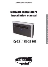
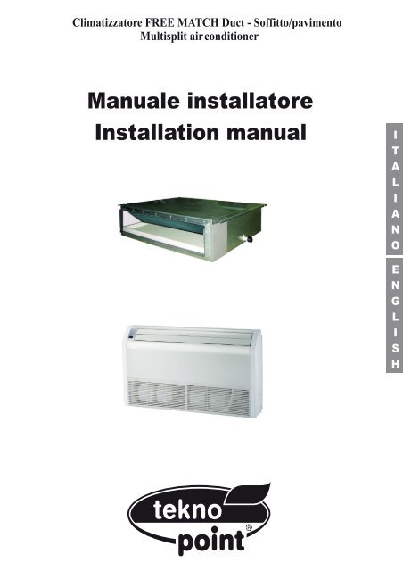
Climatizzatore FREE MATCH Duct - Soffitto/pavimentoMultisplit air conditionerManuale installatoreInstallation manual
I prodotti elettrici ed elettronici di eventuale scarto dovranno essere disposti con i normali rifiuti domestici, masmaltiti a norma di legge RAEE in base alle direttive Europee 2002/96/CE e successive modifiche 2003/108/CE,informandosi presso il Comune di residenza o presso il rivenditore nel caso in cui il prodotto venga sostituitocon uno analogo.Possible wasted electrical or electronic devices/products should not be located together with normaldomestic waste, but disposed according to the current WEEE law in compliance with the EuropeanDirective 2002/96/EC and following modifications 2003/108/EC. Please inform yourself at your local
ITALIANOINDICEI. INFORMAZIONI IMPORTANTI .................................................................................4II. DESCRIZIONE.........................................................................................................6III. SEZIONE DI UTILIZZO ...........................................................................................7III. 1. SISTEMI DI CONTROLLO .................................................................................................. 7III. 1.1. TELECOMANDO.............................................................................................................. 7III. 1.2. FILOCOMANDO (standard)............................................................................................ 11III. 2. NOMI DEI COMPONENTI DELL’APPARECCHIO ............................................................ 17III. 3. OPERAZIONI E PRESTAZIONI DEL CONDIZIONATORE ............................................... 17III. 4. CONSIGLI PER IL FUNZIONAMENTO ECONOMICO...................................................... 17III. 5. REGOLAZIONE DEL FLUSSO DELL’ARIA ...................................................................... 17III. 6. PULIZIA E MANUTENZIONE ............................................................................................ 18III. 7. MALFUNZIONAMENTI...................................................................................................... 19IV. SEZIONE DI INSTALLAZIONE.............................................................................20IV. 1. PRECAUZIONI.................................................................................................................. 20IV. 2. INFORMAZIONI PER L’INSTALLAZIONE ........................................................................ 21IV. 3. NOTE PER L’INSTALLAZIONE ........................................................................................ 21IV. 4 ACCESSORI ...................................................................................................................... 21IV. 5. INSTALLAZIONE DELLE UNITÀ INTERNE...................................................................... 22IV. 5.1 Installazione unità canalizzabile ...................................................................................... 22IV. 5.2 Installazione unità soffitto - pavimento ............................................................................ 26IV. 6. INSTALLAZIONE DELL’UNITÀ ESTERNA ....................................................................... 28IV. 7. CABLAGGIO ELETTRICO ................................................................................................ 31IV. 8. FUNZIONAMENTO DI PROVA......................................................................................... 333. SCHEMI ELETTRICI ............................................................................................................ 653
II. INFORMAZIONI IMPORTANTILeggere interamente questo manuale per un corretto uso del condizionatore al fine di evitare danni a persone e cose.L’uso scorretto della macchina potrebbe causare danni o ferite.È consigliato leggere con attenzione queste informazioni importanti per adeguarsi alle procedure di sicurezza.! AVVERTIMENTOIl condizionatore deve essere installato rispettando le norme di cablaggio nazionale per evitare il rischio di pericolo dimorte.Affidare al fornitore od a personale qualificato l’installazione.All’utente non è permesso installare da solo le unità, per evitare perdite d’acqua, scosse elettriche, incendi ecc.Contattare il fornitore od il centro assistenza più vicino per migliorare le prestazioni, o per la riparazione emanutenzione.Per evitare prestazioni inadeguate o rischio di perdite d’acqua, scosse elettriche ed incendi.Per evitare scosse elettriche, incendi o ferite, spegnere il condizionatore nel caso d’anomalie come odoristrani o incendi e contattare il fornitore od il centro assistenza il più vicino.Non lasciare mai che l’unità ed il telecomando si bagnino.Per evitare scosse elettriche o incendi.Non stare a lungo a diretto contatto con l’aria fredda; aria troppo fredda può causare danni alla salute.Non usare spray infiammabili come spray per capelli o vernici vicino all’unità.Ciò potrebbe causare incendi.Mai mettere le mani nello sbocco d’uscita d’aria o sulle alette orizzontali quando esse sono in movimento.Per evitare il rischio di catturarsi le mani o danneggiare il condizionatore.! PERICOLONon provare da soli a fornire assistenza alla macchina. Questa unità non ha elementi di utilizzo che devono essereaperti e la rimozione del coperchio può esporvi a pericolosi voltaggi. Togliere l’ alimentazione non basta ad evitarepossibili shock elettrici.! PERICOLOMai mettere le mani o oggetti nello sbocco d'entrata e uscita dell'unità. Questa unità contiene una ventola che gira adalta velocità. Un contatto con essa può causare serie lesioni.! PERICOLOPer evitare il rischio di serie scariche elettriche, mai spruzzare o versare acqua o altri liquidi nell'unità.! ATTENZIONEVentilare la stanza ogni tanto mentre il condizionatore è in funzione, specialmente se ci sono altre apparecchiature agas in uso nella stanza. Non seguire questi consigli può causare una perdita di ossigeno nella stanza.! ATTENZIONEPer prevenire una scarica elettrica, spegnere la corrente o staccare la spina prima di iniziare ogni pulizia o altre variemanutenzioni. Seguire le indicazioni per la pulizia nel manuale utente.! ATTENZIONENon usare liquidi o aerosol per la pulizia. Usare un panno soffice e asciutto per pulire l'unità. Per evitare scaricheelettriche, mai provare a pulire l'unità spruzzando acqua su di essa.! PRECAUZIONINon usare detergenti nell'unità. I solventi possono velocemente distruggere gli elementi dell'unità (vaschetta di scaricoe gli elementi dello scambiatore di calore).NOTEPer un'adeguata prestazione, utilizzare l'unità entro la temperatura operativa e le condizioni d'umidità indicate inquesto Manuale. Se l'unità è utilizzata al di fuori di queste indicazioni, questo può causare malfunzionamenti dell'unitào gocciolamento dall'unità interna.Mantenere la temperatura della stanza a un livello confortevole.Pulizia del filtro dell'ariaUn filtro dell'aria intasato, riduce la potenza di raffreddamento. Pulirlo ogni due settimane.Mai aprire porte e finestre oltre ciò che è necessarioPer mantenere fresca o calda l'aria nella stanza, mai aprire porte e finestre oltre ciò che è necessario.Tende:In raffreddamento, chiudere le tende per evitare la luce solare diretta.Rendere uniforme la circolazione dell'aria nella stanzaSistemare la direzione del flusso d'aria per ogni circolazione nella stanza.4
! AVVERTIMENTONon installare l’unità da soli.Un’installazione errata può provocare ferite dovute ad incendi, folgorazioni, cadute dell'unità o perdite d’acqua.Contattare il fornitore dal quale avete acquistato l'unità o un’ installatore speciale.L’installazione deve essere conforme alle istruzioni indicate.L'installazione errata può provocare ferite dovute ad incendi, folgorazioni, cadute dell'unità o perdite d’acqua.Installare saldamente l'unità su di un supporto che può sopportarne il peso.Installare su un supporto debole può provocarne il cedimento e quindi ferite dovute alla caduta dell’unità.Realizzare i collegamenti elettrici rispettando le normative nazionali e gli schemi di cablaggio elettrico diquesto manuale ed assicurarsi di utilizzare un circuito elettrico individuale.Se la capacità del circuito di alimentazione è insufficiente, potrebbero manifestarsi un incendio o una scarica elettrica.Usare i cavi specifici per i cablaggi elettrici ed eseguire i collegamenti correttamente.Collegamenti errati possono causare incendi.Controllare che non ci siano perdite di gas refrigerante dopo l’installazioneAssicurarsi di usare le parti fornite e specificate, durante l’installazione.L'uso di pezzi difettosi può provocare ferite dovute ad incendi, folgorazioni ecc.Fissare saldamente il coperchio che isola la parte elettrica delle unità.Se le coperture elettriche delle unità non sono fissate saldamente, potrebbero manifestarsi incendi o scaricheelettriche causate da polvere, acqua ecc.! ATTENZIONENon installare l'unità in luoghi dove possano propagarsi gas infiammabili.L’unità potrebbe incendiare il gas propagatosi e provocare un’esplosione.Le unità interne dovrebbero essere installate:In un luogo dove c’è sufficiente spazio per l’installazione e la manutenzione.- In un luogo in cui il flusso d’aria possa raggiungere tutti gli angoli.- In un luogo dove le tubazioni e lo scarico condensa possano essere raggiunte facilmente.- In un luogo dove non vi siano perdite di gas infiammabili o gas nocivi/corrosivi.- In un luogo dove non vi sia l’effetto di elevate tensioni e alte frequenze.- In un luogo in cui non vi siano rumore o l’effetto di vibrazioni.! CAUTELEIl posizionamento nei seguenti luoghi può causare malfunzionamenti. (Se non si può evitare, contattare ilfornitore locale)- Luoghi con presenza di olio minerale.- Luoghi in cui l’aria possa essere ricca di salsedine, come nelle vicinanze di spiagge.- Luoghi con presenza di zolfo.- Luoghi in cui ci sono forti variazioni della tensione.- Luoghi in cui vi può essere gas naturale-etano, come le cucine.- Luoghi in cui ci siano fenomeni elettromagnetici legati ad alte frequenze.- Luoghi in cui vi siano gas o sostanze infiammabili.- Luoghi in cui vi sono acidi o gas alcalini.- Altri luoghi per applicazioni speciali.5
II. DESCRIZIONEUNITÀ INTERNAIngresso aria2133Uscita aria43514Uscita ariaIngresso aria28686979UNITÀ ESTERNA 7UNITÀ INTERNAUNITÀ ESTERNA Aletta Tubo di connessione Gruppo ingresso aria con il filtro Cavo di connessione Parte installazione Valvola di arresto Telecomando Ricevitore segnali infrarossi Display Tubo di scarico condensaNota: Tutte le immagini in questo manuale sono soltanto un esempio illustrativo utile alla spiegazione e possonoessere lievemente diverse dal condizionatore che avete acquistato (a seconda del modello).6
III. SEZIONE DI UTILIZZOIII. 1. SISTEMI DI CONTROLLOIII. 1.1. TELECOMANDO♦ DESCRIZIONE DEI TASTI DEL TELECOMANDO1) Tasto ON/OFF, consente di spegnere e accendere il condizionatore.2) Tasti di regolazione consentono di regolare la temperatura ambiente interna eil timer : "+" ne imposta l'aumento, "-" ne imposta la diminuzione.3) Tasto FAN permette di selezionare la velocità della ventilazione: Auto, Bassa( ), Media ( ), Alta ( ).AutoFANAU TOOPER4) Tasto permette di impostare la funzione di purificazione dell’aria.5) Tasto CLOCK consente di impostare l’orario corrente.6) Tasto X-FAN consente di avviare / arrestare il ventilatore interno, questafunzione si utilizza per asciugare i componenti dell'unità interna.7) Tasto TURBO attiva/disattiva la modalità di raffreddamento e riscaldamentoveloce.8) Tasto SLEEP, usato per impostare/cancellare la modalità Sleep,indipendentemente dal modo in cui sta operando il condizionatore.9) Tasto TEMP permette di visualizzare sul display dell’unità la temperatura di setpoint o ambiente.10) Tasto LIGHT per accendere o spegnere il display dell’unità.11) Tasti TIMER-ON/TIEMER-OFF consentono di impostare l’orario diaccensione / spegnimento in automatico del condizionatore.12) Tasto per attivare/disattivare il movimento automatico del deflettore d'aria.13) Tasto permette di impostare la funzione di circolazione dell’aria.14) Tasto I FEEL attiva/disattiva la funzione I FEEL.15) Tasto MODE permette di selezionare la modalità di funzionamento: AUTO -COOL- DRY - FAN – HEAT.1234567FANCLOCKX-FANTURBO88:88I FEELTIMERONTEMPSL EEP°CHOURON-OFFMODE8 9TIMEROFFLIGHT151413121110♦ DESCRIZIONE INDICATORI DEL DISPLAY1) : Indicatore modalità AUTO.2) : Indicatore DEPURATORE ARIA.3) : Indicatore modalità di RAFFREDDAMENTO.4) : Indicatore BLOW.5) : Indicatore modalità di DEUMIDIFICAZIONE.6) : Indicatore modalità TURBO.7) : Indicatore modalità di VENTILAZIONE.8) : Indicatore modalità di RISCALDAMENTO.9) : Indicatore OROLOGIO.10) : Indicatore modalità SLEEP.11) : Indicatore TEMPERATURA.12) : Indicatore oscillazione deflettore.13) : Indicatore modalità LIGHT.14) : Indicatore LOCK.15) : Indicatore TIMER ON-OFF.16) : Indicatore visualizzazione temperatura.17) : Indicatore modalità I FEEL.18) : Indicatore modalità CIRCOLAZIONE ARIA.19) : LED conferma trasmissione segnale.20) FAN : Indicatore velocità ventilatore.123456789DISPLAY20 19FANAUTO88:88OPER°F°CHOURON-OFF1817161510 11 12 13 147
♦ COME INSERIRE/SOSTITUIRE LE BATTERIEUsare due batterie alcaline 1,5 V tipo AAA.(1) Rimuovere il coperchio delle batterie facendolo scivolare nella direzione della freccia.Rimuovere le batterie vecchie e inserire le nuove facendo attenzione ad allinearecorrettamente le polarità (+) e (-).(2) Chiudere il coperchio delle batterie facendolo scivolare nella sua posizioneNote:- Non mettere insieme batterie nuove con vecchie o batterie di tipo differente. Ciò può esserecausa di malfunzionamento.- Se non si usa il telecomando per un lungo periodo le batterie devono essere tolte perevitare danni causati da eventuali perdite.- Le batterie vanno sostituite quando non si riceve alcun "bip" dall’unità interna o sel’indicatore di trasmissione sul telecomando non si accende.Posizionare il telecomando nell’apposito supporto fissato a muro (per assicurare latrasmissione corretta del segnale).♦ COME UTILIZZARE IL TELECOMANDO PER FAR FUNZIONARE L’UNITÀ◊ ACCENSIONE SPEGNIMENTO DELL’UNITÀPremere il tasto per accendere o spegnere l’unità.2314◊ IMPOSTAZIONE DELLA MODALITÀ DI FUNZIONAMENTOPremendo più volte il tasto Mode è possibile cambiare la modalità di funzionamento dell’unità. Sul display comparel’indicazione della modalità di funzionamento selezionato:→ → → →: funzionamento completamente automatico: funzione raffreddamento: funzione deumidificazione: funzionamento solo ventilazione: funzione riscaldamentoCon la scelta della modalità AUTO, l’unità può operare in RAFFREDDAMENTO ed in RISCALDAMENTO in base alladifferenza di temperatura esistente tra la temperatura ambiente e la temperatura selezionata sul telecomando.Quando viene scelta la modalità di raffreddamento, l’unità funziona con set di temperatura libero, abbassando latemperatura in ambiente.Quando viene scelto la modalità di deumidificazione, l’unità funziona, con set di temperatura libero, abbassando cosìprogressivamente la temperatura e l’umidità in ambiente. Nella modalità di deumidificazione il tasto FAN non èutilizzabile.Quando viene scelto il programma di riscaldamento, l’unità funziona, con set di temperatura libero, alzando latemperatura in ambiente. Quando viene scelta la modalità di ventilazione FAN, l’unità funziona senza set ditemperatura, ventilando l’aria dell’ambiente.IMPORTANTE!- Il ventilatore dell’unità si ferma al raggiungimento del valore di temperatura impostato per poi riattivarsiautomaticamente alla velocità minima per evitare fenomeni di stratificazione dell’aria in prossimitàdell’apparecchio.- Selezionando la funzione RAFFREDDAMENTO, DEUMIDIFICAZIONE, il ventilatore potrebbe non avviarsisubito perché presente la funzione ANTI-RISCALDAMENTO. Selezionando la funzione riscaldamento, ilventilatore potrebbe non avviarsi subito perché presente la funzione ANTI-RAFFREDDAMENTO.◊ MODALITÀ SLEEPLa modalità "SLEEP" può essere impostata nel funzionamento di riscaldamento o di raffreddamento.Questa funzione è utile per un ambiente più confortevole quando si va a dormire.Nella modalità SLEEP:- La velocità del ventilatore viene impostata sulla bassa.8
Nota: Se non regolate l'orario entro 10 secondi dopo aver premuto il tasto TIMER - ON, il telecomando abbandoneràautomaticamente la modalità TIMER ON.2) Per confermare l'orario desiderato, premere il tasto TIMER - ON. Un “suono” può essere sentito, e la scritta “ON”smette di lampeggiare.3) Il display del telecomando visualizza l'orario attuale subito dopo l'impostazione del TIMER ON.- Come cancellare TIMER ONPremere di nuovo il tasto TIMER - ON, "un suono" può essere sentito dopodiché l'indicatore sparisce, e la modalitàTIMER ON verrà cancellata.Nota: È analogo per impostare la modalità TIMER OFF per spegnere automaticamente il condizionatore all'oraimpostata.AVVERTENZE- Se impostate la programmazione oraria il telecomando trasmette automaticamente il segnale di accensione ospegnimento all’unità interna agli orari prefissati.- Pertanto mantenete il telecomando in una posizione dalla quale possa trasmettere il segnale correttamente. L’orariopossibile di programmazione è limitato alle 24 ore.- Inizialmente la funzione timer (ON/OFF) viene attivata vicino all’ora attuale.- Il timer non si attiva se allo stesso tempo vengono attivate Timer ON e Timer OFF.◊ FUNZIONE PURIFICAZIONEQuesto tasto è usato per attivare/disattivare la modalità di purificazione dell’aria quando il condizionatore è infunzione.Premendo una volta il tasto la funzione di purificazione dell’aria si attiva ed il display visualizza l’indicatore “ ”.Premendo sullo stesso tasto per la seconda volta, la funzione precedente viene disattivata e l’indicatore “ ” scomparedal display.◊ IMPOSTAZIONE DELLA FUNZIONE I FEELPremere il tasto I FEEL per attivare la funzione. In questo caso l'unità regola automaticamente la temperatura ambientein base alla temperatura rilevata dal sensore di temperatura posizionato nel telecomando.Premere nuovamente questo tasto per annullare la funzione I FEEL.◊ LOCK FUNCTIONPremendo contemporaneamente i tasti "+" e "-", il telecomando bloccherà l’ultima operazione impostata.Tutti i tasti di comando vengono disattivati, incluso il tasto di accensione / spegnimento ON/OFF. Premendonuovamente i due tasti "+" e "-", si riattiveranno le funzioni dei tasti.◊ FUNZIONE °C / °FPremendo contemporaneamente i due tasti "MODE" e "-" ad unità spenta, si potrà scegliere se visualizzare latemperatura in °C o °F.10
III. 1.2. FILOCOMANDO♦ VISTA ESTERNA DEL FILOCOMANDOFig. 1♦ SCHERMO A CRISTALLI LIQUIDI DEL FILOCOMANDOFig. 2: Schermo a cristalli liquidi del filo comando.N. Simboli Descrizione1Funzione oscillazione (SWING)2Funzione sonno (SLEEP)3 Modalità funzionamento unità interna (raffreddamento, deumidificazione, ventilazione eriscaldamento) (MODE)4Funzione sbrinamento unità esterna567Fig. 2Funzione controllo entrata (non ancora disponibile per quest’unità)Funzione blocco (LOCK)Velocità alta, media, bassa o automatica del ventilatore dell’unità interna (FAN SPEED)8 SHIELD Funzioni protezione (tasti, temperatura, accensione/spegnimento, modalità, risparmio)9 TURBO Funzione turbo10Funzione memoria (l’unità interna conserva le impostazioni originali dopo una mancanzaMEMORYd’alimentazione e seguente riaccensione)11 MASTER Filocomando master (non ancora disponibile per questa unità)12Lampeggia quando l’unità è accesa e nessuna funzione è stata selezionata13 SAVE Funzione risparmio energetico14Selezione temperatura ambiente/preselezione15 E-HEATER Funzione riscaldamento elettrico ausiliario16 BLOW Funzione blow17Selezione ora18 QUITE Funzione quiet (2 modalità: quiet e auto quiet).19 SET Si visualizza nel modo selezione11
♦ TASTI DEL FILOCOMANDOFig. 3: Tasti del filocomando.♦ FUNZIONE DEI TASTIN. Nome Funzione1 Enter/cancel1) Funzione selezione e cancellazione;2) Premerlo per 5 secondi per visualizzare la temperatura esterna.2 ▲ 1) Selezione temperatura unità interna, intervallo: 16°C ~ 30°C;2) Selezione ora, intervallo: 0.5 ~ 24H;6 ▼ 3) Selezione tra quiet/auto quiet.3 Fan Selezione velocità ventilatore: alta, media, bassa, automatica4 ModeSelezione modalità funzionamento unità interna: raffreddamento, riscaldamento,ventilazione, deumidificazione5 FunctionSelezione funzione oscillazione, sonno, turbo, risparmio, riscaldamento elettricoausiliario, blow, quiet, etc.7 Timer Selezione ora8 On/Off Accensione/spegnimento unità internaPremerli per 5 secondi quando l’unità è spenta per selezionare/cancellare la funzionememoria (se la funzione memoria è selezionata, l’unità interna conserva le selezioni4+2 ▲ + Mode originali al mancare dell’alimentazione elettrica e della successiva riaccensione; incaso contrario, l’unità interna rimane spenta al ritorno dell’alimentazione – questa è laselezione standard al momento della consegna)3+6 Fan + ▼2+6 ▲ + ▼Una volta premuti contemporaneamente quando l’unità è spenta, il simbolosul display del filocomando.appareAll’accensione dell’unità (senza errori) o quando l’unità è spenta, premerlicontemporaneamente per 5 secondi per selezionare la funzione blocco: in questocaso, nessun tasto sarà operativo. Ripetere l’operazione per annullare la funzione♦ ISTRUZIONI OPERATIVE◊ ACCENSIONE/SPEGNIMENTO (ON/OFF)Premere “On/off” per accendere/spegnere l’unità.Nota: lo schermo mostrerà lo stato di accensione/spegnimento.◊ SELEZIONE MODALITÀ (MODE)Quando l’unità è accesa premere “Mode” per selezionare la modalità di funzionamento: automatica ( ) =>raffreddamento ( ) => deumidificazione ( ) => ventilazione ( ) => riscaldamento ( ).→ → → →◊ SELEZIONE TEMPERATURA (▲▼)Premere ▲(▼) per aumentare (diminuire) la temperatura interna. Premendo il tasto in continuazione, la temperaturaaumenta (diminuisce) di 1°C ogni 0.5 secondi.Nel modo raffreddamento, deumidificazione o riscaldamento, l’intervallo di temperatura selezionabile è: 16°C ~ 30°C.Nel modo ventilazione, la temperatura è fissata standard a 26°C.Nel modo automatico, la temperatura non è regolabile.◊ SELEZIONE VELOCITÀ VENTILATOREPremere il tasto per selezionare una delle seguenti velocità: automatica, bassa, media, alta:Auto Low Middle High12
◊ IMPOSTAZIONE DEL TIMERRegolazione dell’ora: premere “Timer”: lo schermo mostra “xx.x HOUR” con “HOUR” lampeggiante. In questo caso,premere ▲(▼) per aumentare (diminuire) l’ora. Quindi premere “Enter/cancel” per confermare la regolazione.Cancellazione dell’impostazione del TIMER: premere “Timer”: se lo schermo non mostra “xx.x HOUR” significa chela regolazione è annullata.Accendere l’unitàPremere “Timer”per selezionarela funzionePremere▲ o ▼per selezionarel’oraPremere “Enter/cancel”per completare laselezionePremere “Timer”per cancellare laselezione◊ SELEZIONE FUNZIONE OSCILLAZIONE (SWING)Quando l’unità è accesa, premere il tasto per attivare la funzione; premere”Enter/cancel” per confermare.Per disattivare la funzione, quando la funzione oscillazione è attiva, premere “Enter/cancel” per cancellare la funzione.Accenderel’unitàPremere “Function”per selezionare lafunzioneoscillazionePremere “Enter/cancel”per confermarePremere “Function” peaccedere alla paginafunzione oscillazionePremere “Enter/cancel”per cancellare questafunzioneNote:1) La funzione oscillazione sarà la stessa per il modo oscillazione, turbo, blow o quiet.2) Una volta effettuata la selezione, premere il tasto “Enter/cancel” per ritornare alla selezione precedente o perabbandonare automaticamente dopo 5 secondi.◊ SELEZIONE FUNZIONE SONNO (SLEEP)La funzione SLEEP può essere selezionata nel modo raffreddamento o riscaldamento. Questa funzione rende la stanzapiù confortevole durante il sonno.- La velocità del ventilatore si predispone automaticamente su quella bassa.- Premere il tasto “SLEEP” per attivare tale funzione. L’indicatore corrispondente lampeggia sul display. Nel modoraffreddamento/riscaldamento, la temperatura aumenta/diminuisce di 1°C dopo un’ora di funzionamento e di un altro1°C sempre dopo un’ora di funzionamento. Tale temperatura sarà mantenuta fino all’ottava ora di funzionamento edopo l’unità si spegne automaticamente.La funzione sonno si disattiva automaticamente dopo una mancanza di alimentazione e seguente accensione dell’unità;questa funzione non è disponibile nel modo ventilazione.Accenderel’unitàPremere“Function” perattivare lafunzione sonnoPremere ▲o ▼per cambiaremodalitàPremere“Enter/cancel”per selezionarela funzioneSLEEPPremere“Function” pervisualizzare lafunzione SLEEPPremere“Enter/cancel”per cancellare lafunzione SLEEP◊ SELEZIONE FUNZIONE TURBO (TURBO)Funzione turbo: quando la velocità del ventilatore è alta, l’unità può raffreddare o riscaldare velocemente latemperatura della stanza raggiungendo così in poco tempo la temperatura selezionata.Nel modo raffreddamento o riscaldamento premere “Function” fino a selezionare la modalità turbo e quindi premere“Enter/cancel” per confermare la selezione.Quando la funzione turbo è attivata, premere “Function” per accedere alla selezione e quindi premere il tasto“Enter/cancel” per cancellare la funzione.Note:1) Quando la funzione turbo è attivata, se la differenza tra la temperatura della stanza e quella impostata è uguale oinferiore a 2°C (misurata nel minuto seguente), la funzione turbo si disattiva automaticamente.2) La funzione turbo non è disponibile nelle modalità deumidificazione e ventilazione, così come dopo una mancanzad’alimentazione e seguente riaccensione dell’unità. Se la funzione quiet è attiva, quella turbo verrà automaticamenteesclusa.◊ SELEZIONE FUNZIONE RISPARMIO ENERGETICO (SAVE)Risparmio: La funzione risparmio energetico fà sì che il condizionatore funzioni con un intervallo di temperatura ridottoselezionando valori di temperatura inferiori nel modo raffreddamento e deumidificazione e valori superiori nel modoriscaldamento.Selezione funzione risparmio nel modo raffreddamento: quando l’unità è accesa nel modo raffreddamento odeumidificazione, premere “Function” per accedere alla modalità risparmio e quindi premere ▲ o ▼ per selezionare ilvalore limite inferiore nel modo raffreddamento. Quindi, premere “Enter/cancel” per attivare la funzione risparmio. Ilvalore limite inferiore iniziale nel modo raffreddamento è di 26°C.13
Quando la funzione risparmio è attivata, premere “Function” per accedere alla selezione risparmio e quindi premere“Enter/cancel” per cancellare questa funzione.Accenderel’unitàPremere“Function” peraccedere allafunzionerisparmioPremere ▲ o ▼per selezionarela temperaturaPremere“Enter/cancel” perselezionare lapagina dellafunzione risparmio inraffreddamentoPremere“Function” finoa visualizzare lapagina dellafunzionerisparmioPremere“Enter/cancel”per cancellare lafunzionerisparmio nelraffreddamentoSelezione funzione risparmio nel modo riscaldamento: quando l’unità è accesa nel modo riscaldamento, premere“Function” per accedere alla funzione risparmio e quindi premere ▲ o ▼ per selezionare la temperatura; il valore limitemassimo è di 20°C.Una volta attivata la funzione risparmio, premere “Function” per accedere alla pagina risparmio e quindi premere“Enter/cancel” per cancellare questa funzione.Accenderel’unitàPremere“Function” peraccedere allafunzionerisparmioPremere ▲ o▼ perselezionare latemperaturaPremere “Enter /cancel” perselezionare lapagina dellafunzionerisparmio inriscaldamentoPremere“Function” fino avisualizzare lapagina dellafunzionerisparmioPremere“Enter/cancel”per cancellare lafunzionerisparmio nelriscaldamentoNote:1) Il sistema cancella automaticamente la funzione risparmio (mantendo la selezione attuale) se si preme “Function”nella pagina risparmio o se non ci sono altre selezioni entro 5 secondi dalla pressione dell’ultimo tasto.2) La funzione risparmio si memorizza dopo una mancanza d’alimentazione.◊ SELEZIONE FUNZIONE RISCALDAMENTO ELETTRICO AUSILIARIO (E-HEATER)Questa funzione, attiva nel modo riscaldamento, permette di migliorare l’efficienza.La funzione si attiva automaticamente una volta selezionata la modalità riscaldamento.Premere “Function” nel modo riscaldamento per attivare la funzione riscaldamento elettrico ausiliario; premere“Enter/cancel” per cancellare questa selezione.Premere “Function” per selezionare il riscaldamento elettrico ausiliario, se il modo riscaldamento non è attivato, e quindipremere “Enter/cancel” per attivare la funzione.La funzione riscaldamentoelettrico ausiliario viene attivataautomaticamente nel modoriscaldamentoPremere“Function”Premere “Enter/cancel”per cancellare questafunzionePremere “Function”per selezionare lafunzionePremere “Enter/cancel” per attivarela funzione◊ SELEZIONE FUNZIONE BLOW (BLOW)Dopo che l’unità è stata spenta, l’acqua nell’evaporatore dell’unità interna evaporerà automaticamente per evitare laformazione di muffa.Nel modo raffreddamento o deumidificazione, premere “Function” fino a che l’unità entra nel modo blow e quindipremere “Enter/cancel” per attivare questa funzione.Quando la funzione blow è attivata, premere “Function” per accedere alla pagina funzione blow; premere “Enter/cancel”per cancellare questa funzione.Accenderel’unitàPremere “Function” Premere “Enter/cancel” perattivare la funzione blow Premere “Function” Premere “Enter/cancel”per cancellare la funzioneNote:1) Quando la funzione BLOW è attivata, se l’unità interna viene spenta, il ventilatore dell’unità interna continuerà afunzionare per 10 minuti e sullo schermo del filocomando compare “BLOW”. Al contrario, se la funzione blow èdisattivata, il ventilatore dell’unità interna si spegne direttamente.2) La funzione blow non è disponibile nelle modalità ventilazione e riscaldamento.◊ SELEZIONE FUNZIONE QUIET (QUIET)La funzione quiet si divide in: quiet e auto quiet.Premere “Function” fino a selezionare la funzione quiet: quiet o auto lampeggiano sullo schermo. Quindi premere ▲ o▼ per selezionare quiet o auto e poi “Enter/cancel” per confermare.Quando la funzione quiet è attivata, premere “Function” fino a selezionare la funzione quiet: quiet o auto lampeggianosullo schermo. Quindi premere ▲ o ▼ per selezionare quiet o auto e poi “Enter/cancel” per cancellare la selezione.14
Accenderel’unitàPremere “Function”per selezionare lafunzionePremere▲o▼per sceglieretra quiet e autoPremere “Enter/cancel” per attivarela funzionePremere“Function”Premere “Enter/cancel” per cancellarela funzioneNote:1) Quando la funzione quiet è attivata, la velocità del ventilatore si riduce al minimo e non si può regolare.2) Quando la funzione auto quiet è attivata, l’unità funzionerà secondo la differenza tra temperatura della stanza etemperatura impostata. In questo caso, la velocità del ventilatore è regolabile.Differenza tra temperatura della stanza e temperatura impostata: la velocità del ventilatore rimarrà invariata se ladifferenza è ≥ 4°C; la velocità del ventilatore si riduce di un grado se 2°C ≤ differenza temperatura ≤ 3°C; la velocità siriduce al minimo se la differenza è 1°C.3) Quando la funzione auto quiet è attivata, la velocità del ventilatore non può essere aumentata ma solo ridotta. Se lavelocità alta è selezionata manualmente, la funzione si cancellerà automaticamente.4) La funzione auto quiet non è disponibile nelle modalità ventilazione o deumidificazione. La funzione quiet èdisattivata automaticamente dopo una mancanza d’alimentazione e seguente riaccensione dell’unità.◊ ALTRE FUNZIONIa) BloccoAll’accensione del’unità o quando l’unità è spenta, premere ▲ e ▼ contemporaneamente per 5 secondi fino a che ilfilocomando seleziona la funzione blocco. In questo caso il display mostra . Per cancellare la funzione, premere i duetasti nuovamente per altri 5 secondi.Quando la funzione blocco è attivata, nessun altro tasto è utilizzabile.b) MemoriaSelezione memoria: Quando l’unità è spenta, premere “Mode” e ▲ contemporaneamente per 5 secondi perselezionare la funzione. Quando la funzione è attivata, lo schermo mostra la funzione memoria. Se la funzione non èselezionata, l’unità rimarrà spenta dopo una mancanza d’alimentazione e seguente riaccensione.Recupero memoria: Se la funzione memoria è stata selezionata dal filocomando, il filocomando conserverà leimpostazioni originali dopo una mancanza d’alimentazione e seguente riaccensione. Contenuti della memoria:accensione/spegnimento, modalità funzionamento, selezione temperatura, selezione velocità ventilatore, funzionerisparmio e funzione blocco.c) Interrogazione della temperatura esternaQuando l’unità è accesa o spenta, premere “Enter/cancel” per 5 secondi e lo schermo mostrerà la temperaturaambiente dopo un”click”. Questa funzione si cancellerà premendo “Function” o “On/off” o durante la regolazione dellatemperatura. Inoltre si cancellerà automaticamente se nessuna selezione è effettuata entro 10 secondi.♦ ERRORISe si verifica un errore durante il funzionamento del sistema, il corrispondente codice errore sarà visualizzato nelloschermo.Se più errori si verificano nello stesso tempo, i rispettivi codici saranno visualizzati in maniera circolare.Nota: nel caso di errori, spegnere l’unità e contattare l’assistenza tecnica.15
♦ INSTALLAZIONE DEL FILOCOMANDO◊ SELEZIONE DEL POSTO DI INSTALLAZIONE1. Non installare il filocomando in un posto umido o in un luogo esposto alla luce diretta del sole.2. Non installare l'unità e ed il filocomando in un posto in cui c'è interferenze elettromagnetiche.3. Accertarsi che il cavo di comunicazione sia connesso correttamente per evitare malfunzionamenti.◊ INSTALLAZIONE DEL FILOCOMANDONo. DescrizioneParete di installazionePannello posteriore di installazione del filocomandoVite M4X25Pannello frontale del filocomandoVite ST2.2X6.5Attenzione ai seguenti punti durante l'installazione del filocomando:1) Spegnere l’interruttore di corrente e infilare il cavo di connessione nel foro di montaggio nella parete prima realizzarel’installazione del filocomando.2) Estrarre il cavo con 4 coppie intrecciate sul foro di montaggio e quindi farlo passare attraverso il foro rettangolare sulretro del pannello posteriore di installazione del filocomando.3) Appoggiare il pannello posteriore di installazione al muro e poi fissarlo bene con viti M4x25 nei fori di montaggio.4) Infine, inserire il cavo con 4 coppie intrecciate attraverso il foro rettangolare sul pannello posteriore del filocomando epoi fissare il pannello frontale insieme a quello posteriore.Cautela:Il cavo di comunicazione non deve stare assieme al cavo di potenza ed al cavo di connessione interna/esternaall’interno della stessa tubazione di collegamento. Devono tra loro distare almeno 20cm.◊ CAVO DI COLLEGAMENTO DEL FILOCOMANDO CON LA SCHEDA DELL’UNITÀ INTERNA16
III. 2. NOMI DEI COMPONENTI DELL’APPARECCHIOIl condizionatore è composto da unità interne, unità esterna, tubazioni di collegamento e un dispositivo di controllo.III. 3. OPERAZIONI E PRESTAZIONI DEL CONDITIONATOREPer un'adeguata prestazione e per un funzionamento sicuro, utilizzare l'unità sotto le condizioni di temperatura dioperazione e le condizioni d'umidità indicate nella tabella sotto.TemperaturaModalitàTemperatura esterna Temperatura internaRaffreddamento - Riscaldamento -15°C ~ 46°C 16°C ~ 30°C1. Se l'unità è utilizzata al di fuori di queste condizioni di temperatura, si possono verificaremalfunzionamenti o gocciolamento dall'unità interna.! CAUTELA 2. Il fenomeno è normale perché quando all’interno l‘umidità è alta, l’aria si condensa sulla superficiedel condizionatore formando acqua, perciò è consigliabile chiudere porte e finestre.3. La prestazione ottimale sarà raggiunta dentro questi intervalli di temperatura.■ Proprietà tre minuti di protezioneL’unità partirà dopo 3 minuti di ritardo fra due ON/OFF continui per protezione del compressore al riavvio.■ Interruzione di alimentazioneUna possibile interruzione di corrente causerà l’arresto totale del funzionamento dell’unità.● Il LED RUN lampeggerà dopo il ripristino dell’alimentazione.● Premere il tasto ON/OFF sul telecomando per avviare l’unità.● Le radiazioni o le onde elettromagnetiche provenienti da cabine di telefonia senza filo in prossimità potrebberocausare malfunzionamenti dell’unità.Scollegare l’alimentazione e poi ricollegarla di nuovo. Premere il tasto ON/OFF sul telecomando per avviare l’unità.III. 4. CONSIGLI PER IL FUNZIONAMENTO ECONOMICOPer garantire un funzionamento economico si consiglia di seguire le istruzioni indicate qui sotto:■ Regolare correttamente la direzione del flusso d’aria per evitare danni alla salute.■ Impostare la temp. interna per raggiungere il comfort e per evitare il super raffreddamento ed il super riscaldamento.■ In raffreddamento, chiudere le tende per evitare la radiazione solare diretta.■ Per mantenere fresca o calda l’aria nella stanza, mai aprire porte e finestre oltre ciò che è necessario.■ Impostare il Timer per il periodo di funzionamento desiderato.■ Se l’ingresso o l’uscita dell'aria è ostruito; ciò causerà abbassamento di rendimento o spegnimento della macchina.■ Se prevedete di non utilizzare la macchina per un lungo periodo, scollegate l'alimentazione e togliete le batterie daltelecomando. Ripristinate l'alimentazione per garantire una partenza regolare.■ Pulite i filtri almeno una volta ogni due settimane poiché quando sono intasati riducono l'efficienza del condizionatore.III. 5. REGOLAZIONE DEL FLUSSO DELL’ARIA■ Unità tipo Canalizzato* Posizionare l’aletta orizzontalmente nel funzionamento in raffreddamento.* Posizionare l’aletta verso il basso (verticalmente) nel funzionamento in riscaldamento.Nota:1) Regolare l’aletta orizzontale verso il basso se il flusso d’aria è verso il basso,2) Regolare la posizione dell’aletta orizzontale all'interno di circa 40° verso il basso perevitare la formazione delle gocce d'acqua.Regolazione delle alette di ventilazione verso sinistra e destraNota: Per regolare il flusso d'aria verso sinistra / destra, girare l'aletta verticale per variarel’angolo. Un grande angolo d’apertura può causare la formazione delle gocce d'acqua.■ Unità tipo Canalizzato-Soffitto- Funzionamento in raffreddamentoIn raffreddamento, si raccomanda di posizionare l’aletta orizzontalmente per raffreddareefficacemente l'intera stanza.- Funzionamento in riscaldamentoIn riscaldamento, si raccomanda di posizionare l’aletta verso il basso per portare l'ariacalda nella parte bassa della stanza per raggiungere il massimo comfort.
■ Unità tipo Soffitto - pavimento* La direzione del flusso d'aria può essere regolata verso l’alto ed in basso.Oscillazione - autoPremere il tasto SWING per fare oscillare l'aletta automaticamente.Oscillazione manualeRegolare manualmente l'aletta per ottenere un massimo raffreddamento/riscaldamento.In raffreddamento* Regolare l’aletta di ventilazione verticalmente verso il basso.In riscaldamento* Regolare l’aletta verticalmente verso il basso.* Regolare la direzione del flusso d’aria verso sinistra e destra.III. 6. PULIZIA E MANUTENZIONE1) Pulizia del filtro dell’aria- Usare aspirapolvere o acqua per pulire il filtro; se la polvere è in eccesso, usare una spazzola morbida e deldetergente e asciugarlo in luogo fresco.- Il lato di ingresso aria deve essere posizionato verso l'alto quando si usa l'aspirapolvere (riferirsi alla Fig. 6-1) mentredeve essere posizionato verso il basso se si usa l’acqua per il filtro. (Riferirsi alla Fig. 6-2)Fig. 6-1 Fig. 6-2- Re-installare correttamente i filtri e chiudere il pannello frontaleN.B. L’operazione senza filtri d’aria potrebbe causare malfunzionamenti e accumulo della polvere all’interno dell’unità.! CAUTELA Non far asciugare il filtro dell’aria sotto la luce solare diretta o vicino al fuoco.2) Manutenzione consueta (da parte di un professionista)■ Pulizia del filtro dell’aria(1) Pulire il filtro senza smontarlo.(2) Se il condizionatore è installato in un luogo polveroso si deve pulire il filtro frequentemente, almeno una volta ognidue settimane per aumentare l'efficienza del condizionatore.Nota: Prestare attenzione ai seguenti punti prima di cominciare la pulizia del condizionatore.! CAUTELA1) Non toccare i morsetti elettrici con le dita prima di togliere l’alimentazione per evitare scosse.2) Spegnere il condizionatore e staccare l’alimentazione prima di pulire i filtri, per evitare i rischi discosse elettriche o ferite.3) Non usare l’acqua per pulire il filtro per evitare il rischio di scosse elettriche.4) Pulire con attenzione il condizionatore.3) Manutenzione all’inizio della stagioneControllare che l’ingresso e l’uscita d’aria delle unità interna ed esterna non siano ostruiti.Controllare il collegamento del cavo di messa a terra. (viene effettuato da un professionista)Controllare la connessione della linea elettrica. (viene effettuato da un professionista)Controllare le visualizzazioni del display del filocomando dopo il collegamento dell’alimentazione.Nota: Nel caso di malfunzionamento, domandare la documentazione di assistenza al fornitore.4) Manutenzione di fine stagione(1) Fare funzionare il ventilatore per una mezza giornata per asciugare l'unità interna.(2) Spegnere il climatizzatore e scollegare l'alimentazione. Ora, tutti gli indicatori del display del filocomando sispengono.18
III. 7. MALFUNZIONAMENTISe il condizionatore presenta errori di funzionamento, si prega di controllare i seguenti punti prima di domandareassistenza o di riparare.ERROREL’unità non parteL’unità funziona per un attimo e si fermaRaffreddamento non sufficienteRiscaldamento non sufficienteNota:CAUSE POSSIBILI1. Alimentazione staccata.2. Interruzione di corrente.3. Blocco dei tasti di funzionamento.4. Errore di programmazione.1. C’è ostacolo di fronte al condensatore.2. Errore programmazione di controllo.3. Impostazione modalità di raffreddamento mentre la temp. ambienteesterna sopra 43°C.1. Filtro dell’aria sporco o ostruito.2. C’è fonte di calore o ci sono tante persone nella stanza.3. Finestre o porte aperte.4. Ingresso o uscita aria ostruiti.5. Temp. impostata molto alta il che impedisce il raffreddamento.6. Perdita carica refrigerante.7. Errore sensore temp. interna.1. Filtro dell’aria sporco o ostruito.2. Porte o finestre aperte.3. Temp. impostata molto bassa il che impedisce il riscaldamento.4. C’è perdita della carica refrigerante.5. Temp. ambiente esterna inferiore di -5°C.6. Errore di programmazione.In presenza di problemi non risolvibili, spegnere l'apparecchio e contattare il fornitore locale o il servizio d’assistenza piùvicino. Assicurarsi di dare le indicazioni precise che riguardino il tipo di guasto ed il modello dell'apparecchio.19
IV. SEZIONE DI INSTALLAZIONEIV. 1. PRECAUZIONI- Seguire le normative locali, nazionale ed internazionale vigente.- Per una corretta installazione leggere con attenzione questo manuale.- Le seguenti precauzioni sono importanti per la sicurezza degli oggetti. È necessario ricordarle.- Conservare in un posto sicuro questo manuale per future / ulteriori consultazioni.! AVVERTIMENTO Questo simbolo indica pericolo di morte causato da uno scorretto utilizzo.! PRECAUZIONE Questo simbolo indica il pericolo gravi ferite o di danno ad oggetti inseguito ad un utilizzo scorretto.! AVVERTIMENTIL’installatore potrà illustrare all’utente il corretto uso e manutenzione del condizionatore, rimandandolo comunqueall’attenta consultazione del manuale utente installazione del condizionatore.Non installare l’unità da soli.Un’installazione errata può provocare ferite dovute ad incendi, folgorazioni, cadute dell'unità o perdite d’acqua.Contattare il fornitore dal quale avete acquistato l'unità o un’ installatore speciale.L’installazione deve essere conforme alle istruzioni indicate.L'installazione errata può provocare ferite dovute ad incendi, folgorazioni, cadute dell'unità o perdite d’acqua.Installare saldamente l'unità su di un supporto che può sopportarne il peso.Installare su un supporto debole può provocarne il cedimento e quindi ferite dovute alla caduta dell’unità.Realizzare i collegamenti elettrici rispettando le normative nazionale e gli schemi di cablaggio elettrico diquesto manuale ed assicurarsi di utilizzare un circuito elettrico individuale.Se la capacità del circuito di alimentazione è insufficiente, potrebbero manifestarsi un incendio o una scarica elettrica.Usare i cavi specifici per i cablaggi elettrici ed eseguire i collegamenti correttamente.Collegamenti errati possono causare incendi.Controllare che non ci siano perdite di gas refrigerante dopo l’installazioneAssicurarsi di usare le parti fornite e specificate, durante l’installazione.L'uso di pezzi difettosi può provocare ferite dovute ad incendi,folgorazioni ecc.Fissare saldamente il coperchio che isola la parte elettrica delle unità.Se le coperture elettriche delle unità non sono fissate saldamente, potrebbero manifestarsi incendi o scariche elettrichecausate da polvere, acqua ecc.! ATTENZIONENon installare l'unità in luoghi dove possano propagarsi gas infiammabili.L’unità potrebbe incendiare il gas propagatosi e provocare un’esplosione.Le unità interne dovrebbero essere installate:In un luogo dove c’è sufficiente spazio per l’installazione e la manutenzione.- In un luogo in cui il flusso d’aria possa raggiungere tutti gli angoli.- In un luogo dove le tubazioni e lo scarico condensa possano essere raggiunti facilmente.- In un luogo dove non vi siano perdite di gas infiammabili o gas nocivi/corrosivi.- In un luogo dove non vi sia l’effetto di elevate tensioni e alte frequenze.- In un luogo in cui non vi siano rumori o l’effetto di vibrazioni.! CAUTELEL’installazione nei seguenti luoghi può causare malfunzionamenti (se non si può evitare, contattare il fornitore locale)- Luoghi con presenza di olio minerale,- Luoghi in cui l’aria possa essere ricca di salsedine, come nelle vicinanze di spiagge.- Luoghi con presenza di zolfo.- Luoghi in cui ci sono forti variazioni della tensione.- Luoghi in cui vi può essere gas naturale-etano, come le cucine.- Luoghi in cui ci siano fenomeni elettromagnetici legati ad alte frequenze.- Luoghi in cui vi siano gas o sostanze infiammabili.- Luoghi in cui vi sono acidi o gas alcalini.- Altri luoghi per applicazioni speciali.20
TIME R ONECONOMIC ALMTEMPTIMEROFF CONFIRM MO DE F A N SPE E D S WINGCOOL/HEATINGIV. 2. INFORMAZIONI PER L’INSTALLAZIONE- Per una corretta installazione è consigliato leggere queste istruzioni prima di procedere con l’installazione.- Il condizionatore deve essere installato da personale qualificato.- Quando si installa l’unità interna o le sue tubazioni, seguire le istruzione di questo manuale.- Se il condizionatore è in contatto con parti metalliche dell’edificio, si deve provvedere ad isolare l’unità secondo lenorme vigenti.- Attaccare l’alimentazione dopo aver eseguito l’installazione per un controllo completo del condizionatore.- Questo manuale può subire modifiche senza preavviso per scopo di miglioramenti.IV. 3. NOTE PER L’INSTALLAZIONE- Selezionare il luogo di installazione;- Installare prima l’unità interna;- Installare l’unità esterna;- Installare le tubazioni di connessione;- Collegare il tubo di drenaggio;- Effettuare il cablaggio elettrico;- Prova di funzionamento.IV. 4. ACCESSORIControllare che nell'imballo ci siano contenuti gli accessori per l'installazione:No Nome Qty. Profilo1 Pipetta scarico condensa per unità esterna 12 Guarnizione di drenaggio per unità esterna3 Dima di carta per installazione 14 Filocomando o Telecomando 1REPLACELOCK5 Batterie alkaline AAA 1.5V 26 Cavo collegamento alimentazione 1o! Cautele per il telecomando:- Non gettare il telecomando.- Prima dell’installazione, verificare se il luogo d’installazione rientra nel campo d’azione del telecomando.- Tenere il telecomando lontano dalla TV ed altre apparecchiature stereo almeno 1m.- Non installare o posare il telecomando in luoghi direttamente esposti ai raggi solari o vicino a fonti di calore, comestufe, termosifoni etc.- Accertarsi che il polo positivo ed il polo negativo delle batterie siano nelle giuste posizioni quando inserite.21
IV. 5. INSTALLAZIONE DELLE UNITÀ INTERNEIV. 5.1. Installazione unità tipo canalizzato• Usare delle barre d’acciaio per sostenere l’unità interna (Ø 10 mm) e 4 bulloni per il fissaggio.• L’installazione a soffitto dipende dal tipo di costruzione: consultare il costruttore per le procedure specifiche.1) La struttura del soffitto deve garantire una posizione piana dell’unità ed evitare eventuali vibrazioni.2) Tagliare il trave del tetto.3) Rinforzare il posto tagliato e consolidare il trave del tetto.• Terminata l’installazione del corpo principale, tirare il tubo e la linea elettrica nel soffitto.• Prima di procedere con l’installazione, determinare la direzione dei tubi da tirare. Particolarmente nel casod’installazione a soffitto, posizionare i tubi refrigerante, i tubi di scarico condensa ed i cavi di collegamento tra unitàinterna / esterna nei rispettivi alloggiamenti prima di sospendere la macchina.• Installazione dei ganci appendente■ Struttura in legnoMettere l’asse sopra la trave del tetto, quindi installare le barre di sostegno.Legname sopra il traveTrave del soffittoSoffittoBullone vite di sospensioneFig.5-1■ Nuovi mattoni calcestruzziIntarsiare o includere i bulloni delle viti. (riferirsi alla Fig.5-2)Parte incastonata a coltelloFig.5-2Parte incastonata guida■ Nuovi edifici e soffittiUsare vite fischer, mattoni forti di terracotta. (riferirsi alla Fig.5-3)Barra d’acciaioBullone vite d’incastroFig.5-3■ Struttura d’acciaio del trave del tettoInstallare direttamente ed usare la barra di sostegno in acciaio. (riferirsi alla Fig.5-4)Bulloni vite appendenteBulloni di sostegnoBarra in acciaiodi sostegnoFig.5-4■ Come appendere l’unità interna(1) Appendere l’unità interna sui bulloni vite appendenti, stringere il dado sul bullone vite appendente.(2) Per mezzo di una livella, posizionare l’unità interna in un livello piano.LivellaCuscino antivibrazioniDado viteTubodrenagioIngresso ariaFig.5-5Uscita ariaRondellaBullone vitedi sospensioneStaffa di sostegno22
IV. 5.1.1. Dimensioni per l’installazione dell’unità internaAGDBRipresa ariaposterioreScatola comp.elettrici Tubo liquido Tubo gasHTubo di drenaggioCRipresa aria inferioreFFig.5-6JModelliParametriA B C D E F G H I J Attacco tuboliquidoAttacco tubogasDiametro esterno xspessore del tubodi drenaggio2600 W3500 W742 491 662 620 700 615 782 156 200 635 1/4” 3/8”5300 W 942 491 862 820 900 615 982 156 200 635 1/4” 1/2”7100 W 1142 491 1062 1020 1100 615 1182 156 200 635 3/8” 5/8”Φ25 x 1.5IV. 5.1.2. Spazio di installazione dell’unità interna (unità: mm)Dado conRondellaRondella EBULLONE> 500> 2500> 250Fig.5-7Nota: L’altezza minima d’installazione dell’unità interna è di 2.5 m.IV. 5.1.3. Pannello d’ingresso ariaGriglia ingresso ariaIngresso ariaGriglia ingresso ariaIngresso ariaFig.5-8! ATTENZIONETenere le alette della griglia in livello orizzontale (come da figura sopra Fig.5-8) altrimenti l’unità potrebbe emettere fortirumori.23
IV. 5.1.4. Condotti d’aria1. I condotti ingresso e uscita aria devono essere distanziati per evitare la penetrazione dell’aria d’uscita nel condotto diripresa aria.2. L’unità interna è dotata di un filtro d’aria.a) Installazione condotto d’aria rettangolare b) Installazione condotto d’aria rotondoFig.5-9Fig.5-10No. Name No. Name Pannello ripresa aria Raccordo Condotto ripresa aria Staffa di sostegno Tubo scarico condensa Condotto uscita aria Plenum mandata aria Diffusore aria Griglia mandata aria■ Dimensioni flange ripresa e uscita dell’ariaStruttura uscita aria Struttura ripresa ariaFig.5-11Dimensioni Uscita aria RipresaModelli A B C D2600 W / 3500 W 156 662 580 1625300 W 156 862 780 1627100 W 156 1062 980 162c) Installazione condotto ripresa aria1) La posizione di installazione predefinita della flangia rettangolare è situata nella parte posteriore dell’unità mentre lapiastra di chiusura della ripresa dell’aria è situata nella parte inferiore, come illustrato in figure 5-12.Ripresa aria posterioreFlangia rettangolareRipresa aria inferiorePiastra chiusura ripresa ariaFig.5-122) Se si desidera utilizzare la ripresa dell’aria inferiore, è necessario cambiare la posizione della flangia rettangolare e lapiastra di chiusura della ripresa d’aria.3) Utilizzare un rivetto per collegare il condotto ripresa aria con l'apertura ripresa aria dell'unità interna; quindi installareil pannello ripresa aria all'altra estremità del condotto (vedi figura).4) L’installazione della flangia ripresa aria nella posizione inferiore potrebbe produrre più rumore rispetto all’installazionenella parte posteriore dell’unità, quindi è consigliabile in questo caso installare un silenziatore e un plenum per ridurre larumorosità.5) Il metodo di installazione venga scelto in base alle condizioni dell’edificio e della manutenzione, ecc, come mostratoin Fig.5-13.24
Fig.5-13IV. 5.1.6. Installazione del tubo di drenaggio dell’unità interna■ Materiale isolanteTubazioniPVCMateriale isolante Polietilene - 6mm1 Pannello ripresa aria2 Raccordo3 Condotto ripresa aria4 Unità interna5 Condotto uscita aria6. Griglia di controlloNessun spazioUnità principaleTubo PVC rigido■ DrenaggioMateriale isolamento termicoSigillare il materialed’isolamento termicoMateriale isolamento termicoFig.5-14Fig.5-15■ Isolante termicoIsolare termicamente il giunto fasciando le tubazioni per mezzo di isolante.! ATTENZIONE- Il tubo di scarico come le parti di connessione dell’unità interna devono essere isolate termicamente altrimenti si puòformare condensa.- Fissare saldamente le tubazioni in modo da prevenire gocciolamenti.- Non imporre la pressione sulle parti di connessione dello scarico.- Il gradiente in discesa del tubo di scarico deve essere sopra 1/100 e non piegare il tubo di scarico.- Tirare il tubo di drenaggio trasversalmente all’interno di 20m. Installare un sostenitore nel caso che il tubo di scaricosia troppo lungo per prevenire la curvatura.- Riferirsi allo schema di installazione del tubo di drenaggio.1,5m~2mSupportoDislivello (circa 10 cm)Evitare sifoneMateriale termoisolanteInclinazione di 1/100 o piùFig.5-16VP30Inclinazione di 1/100 o piùIV. 5.1.7 Prova di drenaggio• Verificare se il tubo di drenaggio non è ostruito.• Nei nuovi edifici il test di drenaggio dovrebbe essere realizzato prima della pavimentazione del soffitto.25
IV. 5.2 Installazione unità soffitto- pavimentoL’unità interna può essere installata in due modalità differenti a pavimento o a soffitto; le procedure sono simili, bastaseguire le istruzioni descritte per poter eseguire correttamente entrambe le installazioni. Assicurarsi che l’ambiente diinstallazione e gli impianti a cui deve connettersi l’apparecchiatura siano conformi alle normative vigenti.- Determinare la posizione in cui andrà installato il climatizzatore.- Con l’aiuto della dima di cartone, segnare sul soffitto o sulla parete laposizione dei fori per fissare le staffe su cui andrà montata la macchina.- Prima di montare l’unità interna, si raccomanda di togliere la dima.DIMA DI CARTONEPER FORATURAMUROFig.5-17150 cm ≤- Per rimuovere le staffe di sostegno dalla macchina, si deve proseguirecome segue:1) Togliere la griglia di aspirazione premendo la manopola di fissaggio equindi togliere le viti che fissano il pannello laterale del climatizzatore.2) Allentare i bulloni che fissano le staffe alla carcassa della macchina.3) Staccare dalla macchina le staffe sfilandole verso il basso.60 cm ≤100 cm ≤30 cm ≤60 cm ≤Fig.5-18■ INSTALLAZIONE A SOFFITTO4) Forare il soffitto nella posizione segnata con la dima.5) Fissare le staffe, precedentemente rimosse come spiegato al punto1,2,3, al soffitto con dei tappi d’espansione.■ INSTALLAZIONE A PAVIMENTO6) Forare il muro nella posizione segnata con la dima.7) Fissare le staffe, precedentemente rimosse come spiegato al punto 1,2, 3, al muro con dei tappi ad espansione.8) Prima di fissare definitivamente la macchina, chiudere le viti sullestaffe e controllare con una bolla che l’unità sia ben posizionata: questoeviterà problemi di scarico della condensa.Note:Fig.5-19Fig.5-20- Non piegare o strozzare le tubazioni dell’unità interna. Evitare curve di raggio inferiore ai 10 cm.- Non curvare troppe volte lo stesso tratto di tubo altrimenti dopo 3 volte rischia di strozzarsi.- Rimuovere la chiusura dei tubi dell’unità interna solo immediatamente prima di effettuare i collegamenti.- Al fine di evitare la deformazione dei pannelli laterali, si raccomanda di non stringere eccessivamente le viti in fase dimontaggio.! ATTENZIONE: Le immagini indicate sopra sono soltanto un esempio illustrativo e possono essere lievementediverse dal condizionatore che avete acquistato (a seconda del modello).IV. 5.2.2 Collegamento delle tubazioni frigorifereGirare i tubi nella direzione del foro nel muro facendo attenzione a non strozzarli, eunire i tubi di rame, il tubo di scarico per la condensa e i cavi elettrici con un nastroisolante, mantenendo il tubo di scarico della condensa il più basso possibile inmodo che l’acqua possa scorrere liberamente.! CAUTELE- Assicurarsi che non vi sia sporcizia od acqua nelle tubazioni prima di provvedere arealizzare le connessioni.- L’installazione dei tubi di collegamento deve essere effettuata prima del fissaggiodelle unità interna ed esterna.Fig.5-2126
- Mantenere i tubi di connessione asciutti e non lasciate l’umidità penetrare all’interno durante l’installazione.- Coprire completamente i tubi di connessione lato liquido e lato gas con dell’isolamento termico per evitare laformazione di condensa.• Aprire le valvole di arresto dell’unità esterna per connettere il tubo refrigerante con l’unità interna e esterna.Controllare che non ci siano perdite usando un dispositivo cercafughe o acqua saponata.IV. 5.2.2 Collegamento delle tubazioni frigorifereGirare i tubi nella direzione del foro nel muro facendo attenzione a non strozzarli, eunire i tubi di rame, il tubo di scarico per la condensa e i cavi elettrici con un nastroisolante, mantenendo il tubo di scarico della condensa il più basso possibile inFig.5-22modo che l’acqua possa scorrere liberamente.! CAUTELE- Assicurarsi che non vi sia sporcizia od acqua nelle tubazioni prima di provvedere arealizzare le connessioni.- L’installazione dei tubi di collegamento deve essere effettuata prima del fissaggiodelle unità interna ed esterna.- Mantenere i tubi di connessione asciutti e non lasciate l’umidità penetrareall’interno durante l’installazione.- Coprire completamente i tubi di connessione lato liquido e lato gas condell’isolamento termico per evitare la formazione di condensa.Fig.5-23Procedura• Realizzare un foro nella parete (adatto al formato del condotto della parete, 90 mm in generale), regolata suimontaggi quali il condotto della parete e la sua copertura.• Avvolgere i cavi di comunicazione attorno all’isolante delle tubazioni refrigerante.• Passare il tubo di connessione legato tramite il condotto della parete dalla parte esterna. Fare attenzione allaposizione del tubo per non danneggiare la tubazione.• Collegare i tubi• Evacuare l'aria con pompa a vuoto.• Aprire le valvole di arresto dell’unità esterna per connettere il tubo refrigerante con l’unità interna e esterna.• Controllare che non ci siano perdite usando un dispositivo cercafughe o acqua saponata.• Coprire la giunta tra tubazioni e l’unità interna con dell’isolante termico e bloccarlo con del nastro adesivo per garantireun corretto isolamento termico ed evitare così la formazioni di condensa.! CAUTELACoprire le tubazioni di entrambi i lati liquido e gas, le giunte tra tubazioni e le unità interna ed esternacon dell’isolante termico per evitare la formazioni di condensa.IV. 5.2.3. Collegamento del tubo di drenaggio- Lo scarico della condensa dell’unità interna è un punto fondamentale perla buona riuscita dell’installazione.1. Mantenere il tubo per la condensa sulla parte bassa del foro nel muro.2. L’isolante dei tubi in rame deve avere almeno 6 mm di spessore.- Realizzare un foro nel muro che sia, dalla parte esterna di 5-10 mm più basso che all’interno in modo che la pendenzafavorisca il deflusso della condensa. Riferirsi alle figure qui sotto per l’installazione dei tubi.1,5m~2mSupportoEvitare sifoneDislivello (circa 10 cm)Inclinazione di 1/100 o piùVP30Inclinazione di 1/100 o piùMateriale termoisolanteFig. 5-24IV. 5.2.4. Prova di drenaggio• Controllare la tenuta del tubo (evitare perdite all’interno dell’unità e che il tubo di drenaggio non sia ostruito). La figuraqui sotto indica la procedura per testare il collegamento dello scarico condensa e il corretto drenaggio verso lo scoloesterno per evitare ritorni all’interno dell’unità.• Versare nell’uscita d’aria una quantità di acqua di 600 cm³ per collaudo scarico condensa.Uscita ariaFig. 5- 2127
IV. 6. INSTALLAZIONE DELL’UNITÀ ESTERNAIV. 6.1. Luogo di installazione■ L’unità esterna deve essere installata nei seguenti luoghi• In un luogo dove c’è sufficiente spazio per l’installazione e la manutenzione, e dove il vento non può essere forte.• Luoghi con sufficiente ventilazione.• Il supporto deve sostenere il peso dell’unità esterna e deve essere piano e regolare per evitare le vibrazioniaggiuntive.• Luoghi o collocazioni in cui l’aria espulsa dall’unità esterna non possa recare danno ai vicini.• In un luogo dove le tubazioni ed i cavi possano essere installati facilmente.• Dove lo sbocco d’uscita aria non è ostruito.• Dove non vi possono essere perdite di gas infiammabile.• La lunghezza delle tubazioni tra l’unità interna e l’unità esterna deve essere ammissibile.• Nei luoghi vicino alla costa dove il vento può essere forte, installare l’unità esterna contro il muro per garantire ilregolare funzionamento. Usare uno schermo se necessario (Fig.6-1)OVento forteXFig.6-1• Evitare che l’unità sia sottoposta alla radiazione diretta od al calore di altre apparecchiature. Se non si può evitare,prevedere un riparo.• Evitare l’installazione in un luogo in cui l’acqua di scarico condensa durante il funzionamento di riscaldamento possarecare danno alle persone.• Evitare l’installazione in un luogo che sarà oggetto di neve, accumulo di foglie o altri detriti stagionali. Se inevitabile,prevedere un riparo.• Posizionare l’unità esterna in un luogo vicino all’unità interna. Se possibile, rimuovere gli ostacoli attorno dell’unità perfavorire lo scambio termico.• La minima distanza tra l’unità esterna ed gli ostacoli descritte sopra non sono valide per locali a tenuta d’aria o localichiusi. Lasciare liberi almeno 2 delle 3 direzioni (Fig. 6-2).(Muro o ostacolo)Ingresso aria>30cmNIngresso aria>30cmCanale di sostegno>60cm> 220 cmMUscita ariaPFig. 6-2IV. 6.3 Collegamento della pipetta di drenaggio dell’unità esternaLa condensa o l’acqua, che si formano nell’unità esterna durante il funzionamento in riscaldamento, possono essereeliminate attraverso la pipetta di scarico.Installazione: fissare la pipetta di scarico nel foro che si trova sul fondo dell’unità, come mostrato nel disegno a fianco.Collegare il tubo per lo scarico della condensa con la pipetta e fare in modo che l’acqua finisca in uno scarico adatto.28
GuarnizionePipetta didrenaggioForo basamentounità esternaPipetta didrenaggioForo basamentounità esternaGuarnizioneFig. 6-3IV 6.4 Tubazioni refrigerante1. Svasaturaa). Tagliare correttamente un tubo con tagliatubi.magro greggio ronzio90° AFig. 6-4 Fig. 6-5b) Inserire il dado refrigerante e flangiare il tubo.Modelli unità Diametro Diametro Dislivello massimo tra l'unità Diametro svasatura (mm)interna tubo gas tubo liquido esterna e l'unità (m) Min Max2600 W Ø 3/8" 8,3 8,73500 W Ø 3/8" Φ 1/4"12 12,4155300 W Ø 1/2"15,4 15,87100 W Ø 5/8" Ø 3/8"18.6 19.02. Connettere l’unità interna prima e poi l’unità esternaPiegare i tubi a mani se possibile, evitando di romperli.Piegare il tubo con il policeRaggio-min 100 mm Fig. 6-6• L’angolo di curvatura non deve superare 90°.• Piegare se possibile, il tubo di connessione nella parte centrale; maggiore è il raggio di piegatura e meglio è.• Non piegare né tendere il tubo più di tre volte.• Lubrificare le superfici del tubo refrigerante e dei dadi di giunzione con olio e tiralo per 3~4 volte con le mani prima difissare i dadi.Fig. 6-7• Accertarsi d’utilizzare simultaneamente due chiavi per connettere o disconnettere i tubi.Fig.6-829
! CAUTELAUna coppia di torsione troppo grande danneggia la lisciatura della flangia e causerà perdite nelsistema. E’ consigliabile riferirsi alla tabella sotto.Dopo la fine dei lavori di connessione, controllare se ci sono perdite del gas refrigerante.Diametro esternoCopia di torsione NmФ6.4 15 ~ 16 Nm (153 ~ 163 kgf cm)Ф9.5 25 ~ 26 Nm (255 ~ 265 kgf cm)Ф12.7 35 ~ 36 Nm (357 ~ 367 kgf cm)Ф1645 ~ 47 Nm (459 ~ 480 kgf cm)IV. 6.5 Spurgo dell’aria con la pompa del vuotoOperazione valvola di presaa) Valvola d’arresto1. Rimuovere il cappuccio della valvola d’arresto usando una chiave esagonale.2. Una coppia di torsione eccessiva può rompere il corpo della valvola di arresto.3. Accertarsi di fissare saldamente il cappuccio della valvola di arresto.b) Chiusura della valvola di arresto1. Rimuovere il cappuccio della valvola e chiudere la valvola con una chiave esagonale.2. Stringere saldamente la valvola una chiave regolabile.Accertarsi che il cappuccio sia saldamente fissato. Per la coppia di torsione si veda tabella precedente.! CAUTELAUsare un tubo flessibile di carica per la connessione della porta di servizio.Dopo aver fissato il cappuccio, controllare se non ci sono perdite di refrigerante.Porta di servizioDado manutenzioneCappuccioSigelloAstaForo esagonaleFig. 6-9C) Utilizzare una pompa a vuotoUtilizzare una pompa a vuoto per fare il vuoto nelle tubazioni sia dal lato gas che dal lato liquido, preferibilmente inmodo simultaneo.1. Allentare e rimuovere i dadi di servizio delle valvole di arresto A e B, e collegare il tubo flessibile di carica dellamanipola alla porta di servizio della valvola di arresto A (accertarsi che le valvole A e B soni entrambi chiuse)2. Connettere la giunta del tubo flessibile alla pompa a vuoto.3. Aprire completamente la leva “Lo” della manopola.4. Azionare la pompa di vuoto. All’inizio dello spurgo, allentare il dado di servizio della valvola di arresto B percontrollare se l’aria penetra dentro (il suono della pompa cambia, e l’indicatore del decimetro “Compund meter” scendesotto zero). Dopodiché chiudere il dado di servizio.5. Quando l’evacuazione è conclusa, chiudere la manopola “Lo” della valvola manometro e arrestare la pompa a vuoto.Fare il vuoto per oltre 15 minuti, controllare se l’indicatore del tester ha raggiunto -76cmHg (-1X10 Pa).6. Rimuovere il cappuccio delle valvole di arresto A e B per aprire le valvole d’arresto A e B, quindi fissarle.7. Smontare il tubo flessibile di carica dalla porta di servizio della valvola di arresto A e fissare il dado.Unità esternaU n it à intern aALato gas CLato liquidoBValvola di arrestoFig. 6-1030
IV. 6.6. Quantità refrigerante addizionale che deve essere caricataManom etro-76 cm HgBassa pressioneTubo flessibileAlta pressioneTubo flessibilePompa a vuotoPresa di pressioneFig. 6-11La carica refrigerante si effettua solo dopo la realizzazione del cablaggio elettrico.La carica refrigerante potrebbe essere effettuata dopo la realizzazione del test di perdita el’evacuazione dei tubi.Durante l’operazione di carica del gas refrigerante, si deve prestare attenzione per evitare il! CAUTELA fenomeno di liquefazione del gas refrigerante perché la massima carica refrigerante ammissibile nonsi raggiunge mai.Usare il refrigerante R410A per la carica addizionale per evitare il pericolo esplosione e incendi.Aprire lentamente il contenitore del gas refrigerante.Nell’operazione di carica refrigerante usare guanti e occhiali per proteggere gli occhi.- L’unità esterna è caricata con il refrigerante R410A per una lunghezza di una sola linea frigorifera di 5 m. Per unalunghezza superiore ai 5 m è necessario aggiungere una carica di refrigerante di 30 g. per ogni metro eccedente i 5 m.Lunghezza tubo refrigeranteNessuna quantità refrigerante addizionale quando lalunghezza è inferiore di 5m (per linea frigorifera)Quantità refrigerante addizionale quando la lunghezzadel tubo è superiore di 5m (per linea frigorifera)Carica refrigeranteaddizionale-----------30g/mDislivello massimotra l'unità esternae l'unità internaLunghezza massimadelle tubazioni (m)15 20IV. 7. CABLAGGIO ELETTRICO! AVVERTENTE:Leggere con attenzione queste istruzioni prima di eseguire il cablaggio elettrico delle apparecchiature.(1) Controllare se la tensione dell’alimentazione elettrica corrisponde a quella delle specifiche tecnichedell’apparecchiatura.(2) La potenza del circuito di alimentazione deve essere sufficientemente grande.(3) Il cablaggio elettrico deve essere effettuato da personale specializzato.(4) Usare un circuito di alimentazione speciale per il condizionatore, installare un interruttore di dissipazione ed uninterruttore magnetotermico per alimentare il condizionatore.(5) Durante il cablaggio, utilizzare terminali di connessione o cavi di singolo nucleo; la connessione diretta tra il cavomultinucleo e la morsettiera di cablaggio potrebbe causare incendi.(6) Realizzare il cablaggio elettrico rispettando lo schema corretto (vedere l’annesso schemi elettrici).(7) Collegare sempre il cavo di messa a terra per evitare rischi di mancanza d’isolamento.(8) I cavi non devono essere in contatto con il tubo refrigerante, il compressore o il ventilatore.1. Connessione del cavo di alimentazione- Condizionatore con gruppo di alimentazione mono-fase:(1) Togliere il coperchio della scatola componenti elettrici dell’unità esterna.(2) Passare il cavo di alimentazione attraverso il passacavo.(3) Connettere il cavo di alimentazione ai terminali “N(1), (2), (3)” e la messa a terra nella morsettiera della scatola deicomponenti elettrici.(4) Usare fermacavi per fissare il cavo.2. Connessione del cavo segnale del filocomando(1) Aprire il coperchio della scatola componenti elettrici dell’unità interna.(2) Tirare il cavo segnale del filocomando attraverso il passacavo di gomma.(3) Legare il cavo segnale del filocomando al morsetto 4 della scheda elettronica dell’unità interna.31
(4) Usare fermacavi per fissare il cavo segnale del filocomando.■ Specifiche CaviModelliCavo collegamento alimentazione Cavo collegamento interna-esternaSezioneSezione2600 W 1.5 mm² x 3 1.5 mm² x 43500 W 1.5 mm² x 3 1.5 mm² x 45300 W 1.5 mm² x 3 1.5 mm² x 47100 W 2.5 mm² x 3 2.5 mm² x 4Alimentazione principaleAll’esterna■ Schemi di cablaggio1 x 2 DC INVERTER1 x 3 DC INVERTERALIMENTAZIONELBUNITÀ ESTERNAAUNITÀ ESTERNAUNITÀ INTERNA AXT1UNITÀ INTERNA BXT1UNITÀ INTERNA CXT1NLUNITÀ INTERNEBAUNITÀ INTERNEA B C1 x 4 DC INVERTERUNITÀ ESTERNAUNITÀ INTERNA AXT1UNITÀ INTERNA BXT1UNITÀ INTERNA CXT1UNITÀ INTERNA DXT1UNITÀ INTERNEA B C DUNITÀ ESTERNAL N N(1) 2 31 x 5 DC INVERTERUNITÀ INTERNA A UNITÀ INTERNA B UNITÀ INTERNA C UNITÀ INTERNA D UNITÀ INTERNA EN(1) 2 3N(1) 2 3N(1) 2 3N(1) 2 3ALIMENTAZIONE ELETTRICAN(1) 2 3N(1) 2 3N(1) 2 3N(1) 2 3N(1) 2 3UNITÀ INTERNEUNITÀ INTERNA A UNITÀ INTERNA B UNITÀ INTERNA C UNITÀ INTERNA D UNITÀ INTERNA E32
IV. 8. FUNZIONAMENTO DI PROVA• Il test deve essere eseguito solo dopo aver completato l’installazione.• Si prega di controllare i seguenti punti prima di eseguire il test.• Unità interna ed esterna installate correttamente.• Tubazioni e cavi elettrici collegati correttamente.• Test di pressione delle tubazioni eseguito.• Lo scarico condensa funziona regolarmente.• L’isolamento termico è stato eseguito correttamente.• La messa a terra è stata installata correttamente.• La lunghezza delle tubazioni e la carica di refrigerante sono state controllate.• La tensione di alimentazione corrisponde a quella di progetto per il condizionatore.• Ingresso e uscita dell’aria delle unità interne ed esterne non sono ostruite.• Le valvole lato gas e lato liquido sono aperte.• Il condizionatore è stato pre-riscaldato dando tensione.■ Test operationImpostare con il telecomando il condizionatore in modalità raffreddamento, e controllare i seguenti punti come indicatonella parte d’uso di questo manuale. Se avviene qualche malfunzionamento, risolverlo servendosi delle indicazioni delcapitolo “MALFUNZIONAMENTI” di questo manuale.1) Unità internaa) Verificare se accensione e spegnimento dal telecomando avvengono correttamente.b) Verificare se i tasti del controllo remoto sono tutti operativi.c) Verificare se i deflettori o alette si muovono regolarmente.d) Verificare se la temperatura interna è regolata correttamente.e) Verificare se gli indicatori sul ricevitore funzionano.f) Verificare se il tasto manuale funziona correttamente.g) Verificare se lo scarico condensa avviene con regolarità.h) Verificare se ci sono vibrazione o rumori strani durante l’operazione.j) Verificare se la capacità di riscaldamento è adeguata.2) Unità esternaa) Verificare se la presenza di eventuali rumori o vibrazioni fuori norma.b) Verificare se ci sono perdite di gas refrigerante.! CAUTELALa funzione di protezione del condizionatore impedisce l’accensione immediata di nuovo dopo averlospento. Il condizionatore all’intervento della protezione potrà essere riavviato dopo circa 3 minuti dalsuo spegnimento.33
ENGLISHINDEXI. IMPORTANT SAFETY INFORMATION ..................................................................35II. DESCRIPTION.......................................................................................................37III. OPERATION PART...............................................................................................38III. 1. CONTROLL SYSTEMS ..................................................................................................... 38III. 1.1. REMOTE CONTROLLER............................................................................................... 38III. 1.2. WIRE CONTROLLER..................................................................................................... 42III. 2. PARTS NAMES OF THE UNIT.......................................................................................... 48III. 3. AIR CONDITIONER OPERATIONS AND PERFORMANCE............................................. 48III. 4. HINTS FOR ECONOMICAL OPERATION ........................................................................ 48III. 5. ADJUSTING AIR FLOW DIRECTION ............................................................................... 48III. 6. AIR FILTER CLEANING AND MAINTENANCE ................................................................ 49III. 7. TROUBLESHOOTING....................................................................................................... 50IV. INSTALLATION PART..........................................................................................51IV. 1. INSTALLATION PRECAUTION ........................................................................................ 51IV. 2. INSTALLATION INFORMATION....................................................................................... 52IV. 3. INSTALLATION ORDER................................................................................................... 52IV. 4. ACCESSORIES ................................................................................................................ 52IV. 5. INDOOR UNITS INSTALLATION...................................................................................... 52IV. 6. OUTDOOR UNIT INSTALLATION .................................................................................... 59IV. 7. WIRING DIAGRAMS......................................................................................................... 62IV. 8. TEST OPERATION...........................................................................................................64ANNEXES: .................................................................................................................................... 1581. INDOOR UNITS COMBINATION TABLE ............................................................................ 1582. TECHNICAL DATA ..............................................................................................................1593. WIRING DIAGRAMS ........................................................................................................... 16134
I. IMPORTANT SAFETY INFORMATIONTo prevent injury to the user or other people and property damage, the following instructions must be followed. Incorrectoperation due to ignoring of instructions may cause harm or damage.The important safety information is listed which must be read carefully.! WARNINGThe air conditioner must be installed by qualified personsAsk your dealer for installation of the air conditioner.Incomplete installation performed by yourself may result in a water leakage, electric shock, and fire.Ask your dealer for improvement, repair, and maintenance.Incomplete improvement, repair, and maintenance may result in a water leakage, electric shock, and fire.In order to avoid electric shock, fire or injury, or if you detect any abnormality such as smell of fire, turn offthe power supply and call your dealer for instructions.Never let the indoor unit or the remote controller get wet.It may cause an electric shock or a fire.It is not good for your health to expose your body to the air flow for a long time.Never use a flammable spray such as hair spray, lacquer or paint near the unit.It may cause a fire.Do not insert fingers, rods or other objects into the air inlet or outlet.When the fan is rotating at high speed, it will cause injury.! DANGERDo not attempt to service the unit yourself. This unit has no user serviceable components opening and removing thecover will expose you to dangerous voltage. Turning off the power supply will not prevent potential electric shock.! DANGERNever put hands or objects into the air outlet of indoor and outdoor units. This unit contain a fan running at highspeed. Contact with the moving fan will cause serious injury.! DANGERTo avoid the risk of serious electrical shock, never sprinkle or spill water or liquid on the unit.! DANGERVentilate the room occasionally while the air conditioner is in use, especially if there is also a gas appliance in use inthis room. Failure to follow these directions may result in a loss of oxygen in the room.! WARNINGTo prevent electric shock, turn off the power or disconnect the power supply plug before beginning any cleaning orother routine maintenance. Follow the directions for cleaning in the owner’s manual.! WARNINGDo not use liquid cleaners or aerosol cleaners. Use a soft and dry cloth for cleaning the unit. To avoid electric shock,never attempt to clean the unit by sprinkling water on it.! CAUTIONDo not use caustic household dry cleaners in the unit. Drain cleaners can quickly destroy the unit components (drainpan and heat-exchanger coil etc.).NOTEFor proper performance, operate the unit under the usable operating temperature and humidity conditions indicated inthe user’s part of this manual. If the unit is operated beyond these conditions, it may cause malfunctions of the unit ordew dripping from the unit.Maintain room temperature at a comfortable level.Clean air filterA clogged air filter reduces cooling efficiency. Clean it once two weeks.Never open doors and windows more often than necessaryTo keep cool or warm air in the room, never open doors and windows more often than necessary.Windows curtainsIn cooling, close the curtain to avoid direct sunlight.Get uniform circulation of room airAdjust airflow direction for ever circulation of room air.35
! WARNINGBe sure only trained and qualified service personnel to install, repair or service the equipment.Improper installation, repair, and maintenance may result in electric shocks, short-circuit, leaks, fire or other damageto the equipment.Install according to this installation instructions strictly.If installation is defective, it will cause water leakage, electrical shock fire.Install at a strong and firm location which is able to withstand the set’ s weight.If the strength is not enough or installation is not properly done, the set will drop to cause injury.For electrical work, follow the local national wiring standard, regulation and this installation instructions. Anindependent circuit and single outlet must be used.If electrical circuit capacity is not enough or defect in electrical work, it will cause electrical shock fire.Use the specified cable and connect tightly and clamp the cable so that no external force will be acted onthe terminal.If connection or fixing is not perfect, it will cause heat-up or fire at the connection.After completing the installation work, check that the refrigerant does not leak.Toxic gas may be produced if the refrigerant leaks into the room and comes into contact with a source of fire, suchas a fan heater, stove or cooker.Use the attached accessories parts and specified parts for installation.Otherwise, it will cause the set to fall, water leakage, electrical shock fire.Wiring routing must be properly arranged so that control board cover is fixed properly.If control board cover is not fixed perfectly, it will cause heat-up at connection point of terminal, fire or electricalshock.! CAUTIONDon’t install the air conditioner in the following locations:■ There is petrolatum existing.■ There is salty air surrounding (near the coast).■ There is caustic gas (the sulphide, for example) existing in the air (near a hot spring).■ The Volt vibrates violently (in the factories).■ In buses or cabinets.■ In kitchen where it is full of oil gas.■ There is strong electromagnetic wave existing.■ There are inflammable materials or gas.■ Other special conditions.36
II. DESCRIPTIONINDOOR UNITAir inlet2133Air outlet4351Air outletAir inlet428686979OUTDOOR UNIT 7UNITÀ INTERNAUNITÀ ESTERNA Air flow louver (at air outlet) Connecting pipe Air inlet with air filter in it Power supply cable Installation part Stop valve Remote controller Segnla infrared receiverDisplay Drain pipe NOTE: All the pictures in this manual are for explanation purpose only. They may be slightly different from the airconditioner you purchased (depending on model). The actual shape shall prevail.37
III. OPERATION PARTIII. 1. CONTROL SYSTEMSIII. 1.1. REMOTE CONTROLLER♦ DESCRIPTION OF FUNCTIONS OF REMOTE CONTROLLER KEYS1) ON/OFF key to turn the air conditioner on and off.2) ADJUSTING keys to adjust ambient temperature and the timer: "+"increasing, "-" decreasing.3) FAN key to set the fan speed in the sequence that goes from Auto, Low( ), Medium speed ( ), High speed ( ).Auto1FANAU TO88:88OPER°CHOURON-OFF4) key to set AIR function for air change.5) CLOCK key is used to set the current time.6) X-FAN key press it to begin/stop indoor fan which is used to dry thecomponents.7) TURBO key used to enable/disable the rapid cooling or heating mode.8) SLEEP key to set/cancel the Sleep mode regardless of the operating modeof the conditioner.9) TEMP key, press it to show the set point temperature on the unit’s display.10) LIGHT key used to turn on or off the unit’s display.11) TIMER selection button. Press it to set auto-off/auto-on timer.12) SWING key used to set swing angle.13) / key to set HE ALTH / AIR function for air cleaning / for air change.14) I FEEL key to enable/disable the IFEEL mode.15) MODE key to select the operating mode: AUTO - COOL- DRY - FAN -HEAT:234567FANCLOCKX-FANTUR BOI FEELTIMERONTEMPSL EEPMODE8 9TIMEROFFLIGHT151413121110♦ NAME AND FUNCTIONS OF THE DISPLAY INDICATORS1) AUTO mode indicator.2) : AIR CLEANER mode indicator.3) COOL mode indicator4) BLOW mode indicator5) DRY mode indicator6) TURBO mode indicator.7) FAN mode indicator.8) HEAT mode indicator.9) CLOCK indicator10) SLEEP mode indicator11) TEMP indicator.12) Air deflector indicator.13) LIGHT mode indicator14) LOCK indicator15) TIMER ON-OFF mode indicator.16) : Temperature display indicator.17) IFEEL mode indicator.18) AIR RENEWING mode indicator.19) Signal sent confirmation LED.20) FAN Fan Speed indicator123456789DISPLAY20 19FANAUTO88:88OPER°F°CHOURON-OFF1817161510 11 12 13 1438
♦ HOW TO INSERT THE BATTERIESUse two new alkaline type batteries with AAA 1,5V.(1) Slide down the cover of the battery compartment.Remove the used batteries and insert new ones correctly.(2) Reattach the cover by sliding it back into its position.Notes- Do not use old batteries or different type batteries. Such a use may cause remote controlwrong functioning.- If you do not use the remote control more than two weeks, remove the batteries. Damagesmay be caused by possible leakages.- Replace batteries when no "beep" is received from the indoor unit or if the transmissionindicator on the remote controller fails to light.2314♦ HOW TO USE THE REMOTE CONTROL TO OPERATE THE UNIT◊ SWITCHING THE UNIT ON AND OFFPress the key to switch the unit on or off.◊ SETTING THE OPERATING MODEBy pressing the Mode key several times it is possible to change the unit operating mode. The selected operating modesymbol appears on the display.→ → → →: automatic mode: cooling mode: dehumidification mode: fan only mode: heating modeWhen the automatic programme AUTO is selected, the unit may operate in COOLING or HEATING mode dependingon the temperature difference in place between the ambient temperature and the temperature selected on the remotecontrol. When the cooling mode is selected, the unit operates with a free temperature setting, lowering the ambienttemperature. When the dehumidification mode is selected, the unit operates with a free temperature setting,progressively lowering the ambient temperature and humidity. When the dehumidification mode is in operation, the FANbutton cannot be used. When the heating mode is selected, the unit operates with a free temperature setting, raisingthe ambient temperature. When the fan mode is selected, the unit operates without temperature settings, simplyblowing air through the environment.IMPORTANT!- The unit fan stops when the set temperature is reached and is then automatically reactivated at minimumspeed to prevent air stratification phenomena in the vicinity of the appliance.- When the COOLING, DEHUMIDIFICATION mode is selected, the fan may not start up straight away becausethe ANTI-HEATING mode is present. When the HEATING mode is selected, the fan may not start up straightaway because the ANTI-COOLING mode is present.◊ SLEEP MODE SETTINGSLEEP mode can be set in COOLING or HEATING operation mode. This function gives you a morecomfortableenvironment for sleep.In SLEEP mode,- Fan speed is automatically set at low speed.- Press the "SLEEP" button to set the unit to the sleep mode. The SLEEP indicator will light up on the display. Thetemperature increases/decrease in cooling/heating mode operation by 1°C at set intervals. After reaching 2°C the unitmaintains this temperature through to the eighth hour (8 hours) of operation in the "SLEEP" mode and then switches offautomatically.◊ SETTING THE FANBy pressing the FAN key several times it is possible to adjust the fan speed between the three available speeds, or toactivate the AUTO mode. The operating mode appears on the display:Auto39
Auto, Low ( ), Medium speed ( ), High speed ( ).◊ CLOCK SETTINGTo adjust the real time press CLOCK button, then use ''+'' and ''-'' buttons to get the correct time.- Press the key ''+'' / ''-'' once to increase/decrease the time setting by 1 minute.- Press the key ''+'' / ''-'' for 2 seconds to increase/decrease the time setting by 10 minutes.- Press CLOCK button again the real time is set.◊ LIGHT FUNCTIONPress LIGHT button to turn on the display's light and press this button again to turn off the display's light. If the light isturned on, is displayed. If the light is turned off, disappears.◊ TURBO MODE SETTING- TURBO mode is used to start or stop fast cooling and heating at high fan speed.- In Turbo mode, you can set airflow direction or timer. If you want to exit from TURBO mode, press any - TURBO,MODE, FAN or ON/OFF button, the display will return to the original mode.◊ X-FAN FUNCTIONPressing X-FAN button in COOL or DRY mode, the icon is displayed and the indoor fan will continue operation for10 minutes in order to dry the indoor unit even though you have turned off the unit.After energization, X-FAN OFF is defaulted. X-FAN is not available in AUTO, FAN or HEAT mode.◊ TEMP FUNCTIONPress TEMP key to show the set point temperature, indoor ambient temperature and outdoor ambient temperature onthe unit’s display.Note: Outdoor ambient temperature is only displayed for some models.◊ SETTING THE LOUVERIn order to obtain optimal air distribution, adjust the motorised louver, making sure that the air flow is not directly pointedat anyone. For the motorised louver, proceed as follows:By pressing the key it is possible to select swing angle, which circularly changes as belowNote: This remoter is universal. If any command , or is sent out, the unit will carry out the command as .indicates the guide louver swings as:◊ AIR CHANGE FUNCTION SETTINGPress this button to achieve the on and off of scavenging function in operation status. Press this button for the first timeto start scavenging function and LCD displays“ ”. Press this button again to cancel this function.◊ TIMER MODE SETTINGPush the buttons TIMER ON/OFF to set the timer programming as wished in order to switch on an off the air conditionerat the desired time.- How to set TIMER ONTIMER ON button can be used to set the timer programming as wished in order to switch on the appliance at yourdesired time.1) Press TIMER ON button, "ON" flashes on the LCD, then you can press the ''+'' or ''-'' buttons to select your desiredtime for appliance on.- Press the ''+'' / ''-'' button once to increase or decrease the time setting by 1 minute.- Press the key ''+'' / ''-'' for 2 seconds to increase/decrease the time setting by 10 minutes.Note: If you don't set the time in 10 seconds after you press TIMER ON button, the remote controller will exit the TIMERON mode automatically.2) When your desired time displayed on LCD, press the TIMER ON button and confirm it, a beep can be heard and thenthe TIMER indicator "ON" the indoor unit stops flashing.3) After the set timer displayed, the clock will be displayed on the LCD of the remote controller instead of set timer.- How to cancel TIMER ONPress the TIMER ON button again, a "beep" can be heard and the indicator disappears, the TIMER ON mode has beencanceled.Note: It is similar to set TIMER OFF, you can make the appliance switch off automatically at your desired time.CAUTIONS- When you select the timer operation the remote control automatically transmits the timer signal to the indoor unit at thespecified time.OFF40
- Therefore keep the remote control in a location from which it can transmit the signal to the indoor unit properly. Theeffective operation time setted by the remote control is limited in 24 hours.The timer function (ON/OFF) which is theclosest to the actual time will be activated first.- The timer will not work if ON and OFF timer are set at the same time.◊ HEALTHY FUNCTION SETTINGPress this button to achieve the on and off of healthy function in operation status.Press this button for the first time tostart healthy function and the LCD displays“ ”.Press this button again to cancel this function.◊ I FEEL FUNCTION SETTINGPress this button to turn on I FEEL function. The unit automatically adjust temperature according to the sensedtemperature. Press this button again to cancel I FEEL function.◊ LOCK FUNCTIONPress the ''+'' and ''-'' keys at the same time to block the last setting operation by the remote controller.All the keys disabled, including the ON/OFF key. Press the ''+'' and ''-'' keys again to enable the buttons functions.◊ °C / °F functionPress the ''MODE'' and ''-'' buttons at the same time with the unit off to choose the display of temperature in °C and °F.41
III.1.2. WIRED CONTROLLER♦ OUTSIDE VIEW OF THE WIRED CONTROLLER♦ LCD OF THE WIRED CONTROLLERFig. 1Fig. 2Fig. 2 LCD of the Wired ControllerNo. Symbols Description1 Swing function.2 Sleep function.3 Running modes of the indoor unit (Cooling, Dry, Fan and Heating).4 Defrosting function for the outdoor unit.5 Gate-control function (this function is yet unavailable for this unit).6 Lock function.7 High, middle, low or auto fan speed of the indoor unit.8 SHIELD9 TURBO Turbo function.Shield functions (buttons, temperature, On/Off, Mode or Save is shielded orSave is shielded by the remote monitor.10 MEMORYMemory function (The indoor unit resumes the original setting state after power failure andthen power recovery).11 MASTER Master wired controller (this function is yet unavailable for this unit).12 It blinks under on state of the unit without operation of any button.13 SAVE Energy-saving function.14 Ambient/preset temperature value.15 E-HEATER Electric auxiliary heating function.16 BLOW Blow function.17 Timing value.18 QUITE Quiet function (two types: quiet and auto quiet).19 SET It will be displayed under the debugging mode.42
♦ BUTTONS ON THE WIRED CONTROLLERFig. 3 Buttons on the Wired Controller♦ FUNCTION OF THE BUTTONSNo. Name Function1 Enter/cancelFunction selection and cancellation.Press it for 5s to examine the outdoor ambient temperature.2 ▲ Running temperature setting of the indoor unit, range:16°C ~ 30°C.6 ▼Timer setting, range:0.5 ~ 24 hr.Switchover between quiet/auto quiet or among sleep1/sleep2/sleep 3.3 Fan Setting of the high/middle/low/auto fan speed.4 Mode Setting of the Cooling/Heating/Fan/Dry mode of the indoor unit.5 Function Switchover among the functions of Swing/Sleep/Turbo/Save/E-heater/Blow /Quiet etc.7 Timer Timer setting.8 On/Off Turn on/off the indoor unit.4+2 ▲ + ModePress them for 5s under off state of the unit to enter/cancel the Memory function (If memory isset, indoor unit after power failure and then power recovery will resume the original settingstate. If not, the indoor unit is defaulted to be off after power recovery. Memory off is defaultbefore delivery.).3+6 Fan + ▼By pressing them at the same time under off state of the unit, will be displayed on the wiredcontroller for the cooling and heating unit.2+6 ▲ + ▼Upon startup of the unit without malfunction or under off state of the unit,press them at thesame time for 5s to enter the lock state, in which case, any other buttons won’t respond thepress. Repress them for 5s to quit this state.♦ OPERATION INSTRUCTIONS◊ ON/OFF BUTTONPush the button at the condition of OFF, as the wire controller enters into ON operation, simultaneously sends theinformation of operation mode set currently, temperature, fan speed, timer etc. Push the button at the condition of ON, itsimultaneously sends the OFF command.◊ MODE SETTINGIt is used to select mode, push the button one time, then the operation modes will change in turn as follows:AUTO ( ) → COOLING ( ) → DEHUMIDIFY ( ) → FAN ( ) → HEATING ( )◊ ADJUSTMENT BUTTONS ▲ AND ▼Push the button ▲(▼), indoor temperature increases (decrease). Push the button continuously then the temperatureincreases (decreases) by 1°C per 0.5 seconds.In the Cooling, Dry or Heating mode, the temperature setting range is 16°C ~ 30°CIn the fan mode, the setting temperature is fixed at 26°C.In the Auto mode, the setting temperature is unadjustable.◊ FAN SPEED SELECTION BUTTON (FAN SPEED)Select any one fan speed from "AUTO", "LOW"," MED" , and "HIGH”. Each time push the button, the fan speed willchange in turn as fellow.Auto Low Middle High43
◊ TIMER SETTINGUnder OFF/ON state of the unit, push the button Timer to set TIMER ON/OFF, each time you press the button ▲(▼)thetime increases (decreases) by 0.5 hours. Press the button Enter/Cancel if you want to confirm/cancel the TIMERON/OFF setting.Turn on the unit,without setting timerfunctionPress «Timer»button to set thetimer functionPress «▲or▼» to adjusttimePress «Enter/cancel»button to finish timersettingPress «Timer»button to canceltimer setting◊ SWING SETTING- Push the Function button for the first time when operation, it will start the swing function. Push the Enter/Cancel buttonto make a confirmation.- When swing function is on, press the Function button to enter the Swing setting interface, after that press Enter/cancelto cancel this function.Turn on the unit,without turning onswing functionPress «Function»button into swingstatePress «Enter/cancel»button to confirmPress «Function»button into swingstatePress «Enter/cancel»button to cancel swingfunctionNote:1) Sleep, Save, Turbo, Blow or Quiet setting is the same as the Swing setting.2) After the setting has been done, it has to press the key “Enter/cancel” to back to the setting status or quitautomatically five seconds later.◊ SLEEP SETTINGSLEEP mode can be set in COOLING or HEATING operation mode. This function gives you a morecomfortableenvironment for sleep.In SLEEP mode,- Fan speed is automatically set at low speed.- Press the "SLEEP" button to set the unit to the sleep mode. The SLEEP indicator will light up on the display. Thetemperature increases/decrease in cooling/heating mode operation by 1°C at set intervals. After reaching 2°C the unitmaintains this temperature through to the eighth hour (8 hours) of operation in the "SLEEP" mode and then switches offautomatically.Turn on the unit,without turning on sleep modePress «Function»button into sleep statePress «▲ or▼»switch modesPress «Enter/Cancel» to setsleep modePress «Function»button into sleep statePress «Function»button into sleepstate◊ TURBO SETTINGTurbo function: The unit at the high fan speed can realize quick cooling or heating so that the room temperature canquickly approach the setting value.In the Cooling or Heating mode, press Function till the unit enters the Turbo setting interface and then pressEnter/Cancel to confirm the setting.When the Turbo function is activated, press Function to enter the Turbo setting interface and then press Enter/Cancel tocancel this function.Notes:1) When the Turbo function is activated, if the difference between the room temperature and set temperature is at orbelow 2°C (detected in successive 1 min.), the Turbo function will be automatically deactivated.2) Turbo function is unavailable in the Dry and Fan mode. And the Turbo function is off after power failure and thenpower recovery. If Quiet function is on, Turbo function will be canceled subsequently.◊ SAVE SETTINGSave: Energy saving which will result the air conditioner runs in smaller temperature range is realized by setting lowerlimited value in the Cooling or Dry mode and upper limited value in the Heating mode.Save Setting for Cooling:Under the “On” state and in the Cooling or Dry mode of the unit, press Function to enter the Save setting interface andthen press ▲ or▼ to adjust the lower limited value in the cooling mode. After that, press Enter/Cancel to activate theSave function. The initial lower limited value in the Cooling mode is 26°C.When the Save function is activated, press Function to enter the Save setting interface and then press Enter/cancel tocancel this function.44
Turn on theunit, withoutturning on savefunctionPress«Function»button into savestatePress «▲or▼» toadjust temp.Press «Enter/Cancel» to setsave functionfor coolingPress «Function»button into savestatePress «Function»button to cancelsave function forcoolingSave Setting for Heating:Under on state or in the Heating mode of the unit, press Function to enter the Save setting interface and then press ▲or ▼ to adjust upper limited value in the heating mode is 20°C.After the Saving function is activated, press Function to enter the Save setting interface and then press Enter/Cancel tocancel this function.Turn on theunit, withoutturning on savefunctionPress«Function»button into savestatePress «▲or▼» to adjusttemp.Press «Enter/Cancel» toset savefunction forheatingPress «Function»button into savestatePress «Function»button to cancelsave function forheatingNotes:1) If press Function on the Save setting interface or if there is not any operation for 5s after last button press, the Savesetting will be canceled automatically by the system, with memorizing the present setting data.2) When power is on after the power failure, the Save function will be memorized.◊ E-HEATER SETTINGE-heater (auxiliary electric heating function): In the Heating mode, E-heater is allowed to be turned on for Improvment ofefficiency.Once the wired controller or the remote controller enters the Heating mode, this function will be turned on automatically.Press Function in the Heating mode to enter the E-heater setting interface and then press Enter/cancel to cancel thisfunction.Press Function to enter the E-heater setting interface, if the E-heater function is not activated, and then pressEnter/Cancel to turn it on.Auxiliary electricheating functionwill beautomaticallyturned on underheating modePress «Function»button into thisfunction statePress «▲or▼» to adjusttemp.Press «Enter/Cancel» toturn off thisfunctionPress «Function»button intoauxiliary electricheating functionPress«Function»button to cancelsave function forheating◊ BLOW SETTINGBlow function: After the unit is turned off, the water in evaporator of indoor unit will be automatically evaporated toavoid mildew.In the Cooling or Dry mode, press Function till the unit enters the Blow setting interface and then press Enter/Cancel toactive this function.When the Blow function is activated, press Function to the Blow setting interface and then press Enter/ Cancel to cancelthis function.Turn on the unit,without turning onthe blow functionPress «Function»button into blowstatePress «Enter/Cancel» to setblow functionPress «Function»button into blowstatePress «Enter/Cancel» to set blowfunctionNotes:1) When the Blow function is activated, if turning off the unit by pressing On/Off or by the remote controller, the indoorfan will run at the low fan speed for 10 min, with “BLOW” displayed on the LCD.While, if the Blow function is deactivated, the indoor fan will be turned off directly.2) Blow function is unavailable in the Fan or Heating mode.◊ QUIET SETTINGQuiet function consists of two kinds: quiet and auto quiet.Press Function till the unit enters the Quite setting interface, with “Quiet” or “Auto” blinking. In this case, press ▲ or ▼to switch between Quiet and Auto and then press Enter/cancel to make a confirmation.When the Quiet function is activated, press Function till the unit enters the Quite setting interface, with “Quite” or “Auto”blinking. Then press Enter/cancel to cancel this function.Turn on the unit,without turning on Quiet functionPress «Function»button into QuietstatePress «EnterPress «▲ or▼»to change state /Cancel» toturn on thisfunctionPress «Function»button into QuietstatePress «Enter/Cancel» to turnoff Quiet function45
Notes:1) When the Quite function is activated, the fan speed is low and un-adjustable.2) When the Auto Quite function is activated, the unit will run according to the difference between the room temperatureand the setting temperature. In this case, the fan speed is adjustable.Difference between the room temperature and the setting temperature: the fan speed will keep its current state if thetemperature difference ≥ 4°C ; the fan speed will reduce one grade if 2°C ≤ the temperature difference ≤ 3°C ; the fanspeed will be at min. grade if the temperature difference 1°C.3) When the Auto Quiet function is on, the fan speed can not be raised but reduced. If the high fan speed is manuallyadjusted, the function will quit automatically.4) There is not Auto Quiet function in the Fan or Dry mode. Quiet off is default after power failure and then powerrecovery.◊ OTHER FUNCTIONSa) LockUpon startup of the unit without malfunction or under the “Off” state of the unit, press ▲ and ▼ at the same time for 5still the wired controller enters the Lock function. In this case, LCD displays . After that, repress these two buttons atthat, repress these two buttons at the same time for 5s to quit this function.Under the Lock state, any other button press won’t get any response.b) MemoryMemory switchover: Under the “Off” state of the unit, press Mode and ▲ at the same time for 5s to switch memorystates between memory on and memory off. When this function is activated, Memory will be displayed. If this function isnot set, the unit will be under the “Off” state after power failure and then power recovery.Memory recovery: If this function has been set for the wired controller, the wired controller after power failure willresume its original running state upon power recovery. Memory contents: On/Off, Mode, set temperature, set fan speed,Save function and Lock function.c) Enquiry of the Outdoor Ambient TemperatureUnder the “On” or “Off” state of the unit, press Enter/Cancel for 5s, and the outdoor ambient temperature will bedisplayed after a sound of click. This enquiry state will quit by pressing Function or On/Off or during the temperatureadjustment. If there is not any operation for 10s, it will also quit automatically.♦ ERRORSIf there is an error occurring during the operation of the system, the error code will be displayed on the LCD, as show infigure below. If multi errors occur at the same time, their codes will be displayed circularly.Note: In event of any error, please turn off the unit and contact the professionally skilled personnel.46
♦ INSTALLATION OF WIRED CONTROLLER◊ INSTALLATION LOCATION OF WIRED CONTROLLER1. Never install wired controller at wet place or under sunlight directly.2. Never install the unit and wired controller at the place where there is electromagnetic interference.3. Make sure communication line is connected into correct port to avoid communication malfunction.◊ INSTALLATION OF WIRED CONTROLLERNo.DescriptionSocket’s base box installed in the wallSoleplate of controllerScrew M4X25Front panel of controllerScrew ST2.2X6.5Pay attention to the following items during installation of wired controller:1) Cut off power supply of heavy-current wire embedded in mounting hole in the wall before installation. It is prohibitedto perform the whole procedure with electricity.2) Pull out 4-core twisted pair line in mounting hole and then make it through the rectangle hole at the back ofcontroller’s soleplate.3) Joint the controller’s soleplate on wall face and then fix it in mounting hole with screws M4X25.4) At last, insert the 4-core twisted pair through rectangle hole into controller’s slot and buckle the front panel andsoleplate of controller together.Caution:To ensure normal communication of unit, signal line and wiring (communication) of wired controller should separatefrom power cord and indoor/outdoor connection lines. The distance between them should be kept 20cm in min.◊ CONNECTING CABLE BETWEEN INDOOR PCB AND WIRE CONTROLLER47
III. 2. PARTS NAMES OF THE UNITThe air conditioner consists of indoor unit, outdoor unit, connecting pipe and remote controller. NOTE: All the pictures in this manual are for explanation purpose only. They may be slightly different from the airconditioner you purchased (depending on model). The actual shape shall prevail.III. 3. AIR CONDITIONER OPERATIONS AND PERFORMANCEUse the system in the following temperature for safe and effective operation. The Max operation temperature for the airconditioner. (Cooling/Heating)Temperature Outdoor temperature Room temperatureModeCooling / Heating operating -15°C ~ 46 °C 16 °C ~ 30 °C! CAUTION1. For proper performance, operate the unit under the usable operating temperature conditionsindicated in this owner’s manual. If the unit is operated beyond these condition, it may causemalfunctions of the unit or dew dripping from the unit2. The phenomenon is normal that the surface of air conditioning may condense water when therelative larger humidity in room, please close the door and window.3. Optimum performance will be achieved within these operating temperature range.■ Three-minute protection featureA protection feature prevents the air conditioner from being activated for approximately 3 minutes when it restartsimmediately after operation.■ Power failurePower failure during operation will stop the unit completely.● The RUN lamp on the indoor unit will start flashing when power is restored.● To restart operation, push the button on the remote controller.● Lightning or a car wireless telephone operating nearby may cause the unit to malfunction.Disconnect the unit with the power and then connect the unit with the power again. Push the button on the remotecontroller to restart operation.III. 4. HINTS FOR ECONOMICAL OPERATIONThe following should be noticed to ensure an economical operation:■ Adjust the airflow direction properly to avoid winding toward your body.■ Adjust the room temperature properly to get a comfortable situation and to avoid super cooling and superheat.■ In cooling, close the curtains to avoid direct sunlight.■ To keep cool or warm air in the room, never open doors or windows more often than necessary.■ Set the timer for the desired operating time.■ Never put obstructions near the air outlet or the air inlet. Or it will cause lower efficiency, even a sudden stop.■ If you don’t plan to use the unit for a long time, please disconnect power and remove the batteries from the remotecontroller. When the power switch is connected, some energy will be consumed, even if the air conditioner isn’t inoperation. So please disconnect the power to save energy. And please switch the power on 12 hours before you restartthe unit to ensure a smooth operation.■ A clogged air filter will reduce cooling or heating efficiency, please clean it once two weeks.III. 5. ADJUSTING AIR FLOW DIRECTION■ Duct Type* Adjust the louver horizontally when cooling.* Adjust the louver down (vertically) when heating.Note:1 Adjust the horizontal louver down when the airflow is down.2 The slant angle of horizontal louver must be less than 40° otherwise the waterdrop will be caused.Adjust left and right.Note:When adjusting airflow left/right, turn the vertical louver to certain angles and theangle isn’t too big otherwise the water drop will be caused.< 40°Aletta verticaleVertical louver48
■ Duct-Ceiling TypeThe following is how to adjust the airflow direction when the air outlet parts (soldseparately) are used with the indoor unit.- Cooling modeTo effectively cool the whole room, please adjust the louver horizontally.- Heating modeTo effectively heat the bottom of the room please set the louver downwards.■ Ceiling-Floor TypeAdjust the air direction up and down.* Auto-swing:Press SWING button, the louver will swing up and down automatically.* Manual SwingAdjust the louver to achieve better cooling/heating effects.- When coolingAdjust the louver horizontally.- When heating* Adjust the louver downwards (vertically).* Adjust the airflow direction left and right.III. 6. AIR FILTER CLEANING AND MAINTENANCE1) Air filter cleaning- Vacuum cleaner or pure water may be used to clean the air filter. If the dust accumulation is too heavy, please use softbrush and mild detergent to clean it and dry out in cool place.- The air-in side should face up when using vacuum cleaner. (Refer to Fig. 6-1) The air-in side should face down whenusing water. (Refer to Fig. 6-2)Fig. 6-1 Fig. 6-2Set the air filter and the especial function filter as they were and close the front panel.Note: Operation without air filters may result in troubles, as dust will accumulate inside the indoor unit.! CAUTION Do not dry out the air filter under direct sunshine or with fire.2) Routine MaintenanceCleaning the Air Filter (Operating by the professional)Do not disassemble the air filter when cleaning it. Otherwise failure may be caused.If the air-conditioning unit is used in an environment with much dust, you should clean the air filter frequently (onceevery two weeks).Note: You shall pay attention to the following matters when cleaning the air-conditioning unit.! CAUTION1) Cut off all power supply before contacting the line connecting equipment.2) Only clean the air-conditioning unit after the unit is shut off and the power supply is disconnected.Otherwise electrical shock or injury may be caused.3) Do not use water to clean the air-conditioning unit. Otherwise there may be electrical shock.4) Take care when cleaning the air-conditioning unit. Use a steady stepping stand.3) Maintenance at the Beginning of Operating SeasonCheck the air inlet and outlet of the indoor and outdoor units to confirm there is no blockage.Check to see if the grounding wire is in good condition; (Operating by the professional)Check to see if the line connection is in good condition; (Operating by the professional)49
Check if there is any word displaying on the LCD of the wire controller after connecting the unit to power supply.Note: If there is any abnormal condition, ask after sales personnel to offer guidance.4) Maintenance at the End of the Operational Season(1) When the weather is clear, operate the unit under fan mode for half a day, so as to dry the inside of the unit.(2) If not to use the air-conditioning unit for a long time, please cut off the power supply. Now the words on the LCD ofthe wire controller shall disappear.III. 7. TROUBLESHOOTINGIf your air-conditioning unit suffers from abnormal operation or failure, please first check the following points beforerepair:FailurePossible ReasonsThe unit cannot be started.1. The power supply is not connected.2. Electrical leakage of air-conditioning unit causes tripping ofleakage switch.3. The operating keys are locked.4. The control loop has failure.The unit operates for a while and then stops.Poor cooling effect.1. There is obstacle in front of the condenser.2. The control loop is abnormal.3. Cooling operation is selected when the outdoor ambienttemperature is above 43°C.1. The air filter is dirty or blocked.2. There is heat source or too many people inside the room.3. The door or window is open.4. There is obstacle at the air intake or outlet.5. The set temperature is too high thus cooling is hindered.6. There is refrigerant leakage.7. The performance of room temperature sensor becomes worse1. The air filter is dirty or blocked.2. The door or window is not firmly closed.3. The set room temperature is too low thus heating is hindered.Poor heating effect4. There is refrigerant leakage.5. The outdoor ambient temperature is lower than -5°C.6. Control line is abnormal.Note:After carrying out the check of the above items and taking relevant measures to solve the problems found but the airconditioningunit still does not function well, please stop the operation of the unit immediately and contact the localservice agency designated by the company. Only ask professional serviceman to check and repair the unit.50
IV. INSTALLATION PARTIV. 1 INSTALLATION PRECAUTION■ Be sure to be in conformity with the local, national and international laws and regulations.■ Read the manual carefully before installation.■ The following pre<strong>caution</strong>s include important safety items. Observe them and never forget.■ Keep this manual in a handy place for future reference.! WARNING Failure to observe a warning may result in death.! CAUTION Failure to observe a <strong>caution</strong> may result in injury or damage to the equipment.! WARNINGAfter completing the installation, make sure that the unit operates properly during the start-up operation. Please instructthe customer on how to operate the unit and keep it maintained. Also, inform customers that they should store thisinstallation manual along with the owner’s manual for future reference.! WARNINGBe sure only trained and qualified service personnel to install, repair or service the equipment.Improper installation, repair, and maintenance may result in electric shocks, short-circuit, leaks, fire or other damage tothe equipment.Install according to this installation instructions strictly.If installation is defective, it will cause water leakage, electrical shock fire.Install at a strong and firm location, which is able to withstand the set’s weight.If the strength is not enough or installation is not properly done, the set will drop to cause injury.For electrical work, follow the local national wiring standard, regulation and these installation instructions. Anindependent circuit and single outlet must be used.If electrical circuit capacity is not enough or defect in electrical work, it will cause electrical shock fire.Use the specified cable and connect tightly and clamp the cable so that no external force will be acted on theterminal.If connection or fixing is not perfect, it will cause heat-up or fire at the connection.After completing the installation work, check that the refrigerant does not leak.Toxic gas may be produced if the refrigerant leaks into the room and comes into contact with a source of fire, such as afan heater, stove or cooker.Use the attached accessories parts and specified parts for installation.Otherwise, it will cause the set to fall, water leakage, and electrical shock fire.Wiring routing must be properly arranged so that control board cover is fixed properly.If control board cover is not fixed perfectly, it will cause heat-up at connection point of terminal, fire or electrical shock.! CAUTIONDon’t install the air conditioner in the following locations:■ There is petrolatum existing.■ There is salty air surrounding (near the coast).■ There is caustic gas (the sulphide, for example) existing in the air (near a hot spring).■ The Volt vibrates violently (in the factories).■ In buses or cabinets.■ In kitchen where it is full of oil gas.■ There is strong electromagnetic wave existing.■ There are inflammable materials or gas.■ Other special conditions.51
TIM E R O NECON OM ICALMTEMPTIMER OFF CO NFIR M MODE FAN SPEE D SWINGLO CK COOL/HEATINGIV. 2. INSTALLATION INFORMATION■ To install properly, please read this “installation manual” at first.■ The air conditioner must be installed by qualified persons.■ When installing the indoor unit or its tubing, please follow this manual as strictly as possible.■ If the air conditioner is installed on a metal part of the building, it must be electrically insulated according to therelevant standards to electrical appliances.■ When all the installation work is finished, please turn on the power only after a thorough check.■ Regret for no further announcement if there is any change of this manual caused by product improvement.IV. 3. INSTALLATION ORDER■ Select the location;■ Install the indoor unit;■ Install the outdoor unit;■ Install the connecting pipe;■ Connect the drainpipe,■ Wiring;■ Test operation.IV. 4. ACCESSORIESCheck whether the following fittings are of full scope. If there are some spare fittings, please restore them carefully.No Name Qty. Shape1 Outdoor drain elbow 12 Outdoor drain stem3 Paper pattern for installation 14 Wire controller or Remote controller 1REPLACEor5 Alkaline dry batteries AAA 1.5V 26 Power connection cord 1Cautions on remote controller installation:■ Never throw or beat the controller.■ Before installation, operate the remote controller to determine its location in a reception range.■ Keep the remote controller at least 1m apart from the nearest TV set or stereo equipment. (it is necessary to preventimage disturbances or noise interferences.)■ Do not install the remote controller in a place exposed to direct sunlight or close to a heating source, such as a stove.■ Note that the positive and negative poles are right positions when loading batteries.IV. 5. INDOOR UNITS INSTALLATIONIV. 5.1. Ducted type unit install• Installing φ10 hanging screw bolts. (4 bolts)• Please refer to the following figure for the distance measurement between the screw bolts.• Please install with φ10 hanging screw bolts.• The handling to the ceiling varies from the constructions; consult the construction personnels for the specificprocedures.1. The size of the ceiling to be handled to keep the ceiling flat. Consolidate the roof beam for possible vibration.2. Cut off the roof beam.3. Strengthen the place cut off, and consolidate the roof beam.• Carry out the pipe and line operation in the ceiling after finishing the installation of the main body. While choosingwhere to start the operation, determine the direction of the pipes to be drawn out. Especially in case there is a ceiling,position the refrigerant pipes, drain pipes, indoor & outdoor lines to the connection places before hanging up themachine.• The installation of hanging screw bolts.52
■ Wooden constructionPut the square timber transversely over the roof beam, then install the hanging screw bolts. (Refer to Fig. 5-1)Timber over the beamRoof beamCeilingHanging screw boltsFig. 5-1■ New concrete bricksInlaying or embedding the screw bolts. (Refer to Fig. 5-2)(Blade shape insertion)(Slide insertion)Fig. 5-2■ For original concrete bricksUse embedding screw bold, crock and stick harness. (Refer to Fig. 5-3)Steel barEmbedding screw bolt(Pipe hanging and embeddingscrew bolt)Fig. 5-3■ Steel roof beam structureInstall and use directly the supporting angle steel. (Refer to Fig. 5-4)Hanging screw boltHanging boltsSupportingangle steelFig. 5-4■ Overhanging the indoor unit(1) Overhang the indoor unit onto the hanging screw bolts with block.(2) Position the indoor unit in a flat level by using the level indicator, unless it may cause leakage.Horizontality check deviceShockproof cushionScrew nutAir inletAir outletWasherHangingscrew boltOverhang partFig.5-553
IV. 5.1.1. Installation dimensions of the indoor unitFig.5-6ModelsParametersA B C D E F G H I JConnectingpipe (Liquidpipe)Connectingpipe(Gas pipe)Drainage pipeOutdoor diameter(Wall thickness)2600 W3500 W742 491 662 620 700 615 782 156 200 635 ¼’’ 3/8”5300 W 942 491 862 820 900 615 982 156 200 635 ¼” ½”7100 W 1142 491 1062 1020 1100 615 1182 156 200 635 3/8” 5/8”Φ25X1.5IV. 5.1.2. Dimension requirement of the installation space of indoor unit (mm)Nut withWasherNut springWasherFig.5-7Note: The height of installation for the indoor unit should be 2.5m above.IV. 5.1.3. Air Inlet Panel of Air Return BoxAir-in grilleAir inletAir-in grilleAir inletFig. 5-8! CAUTIONMake the air inlet grille and air inlet direction in parallel (see the figure above), which may cause loud noise.IV. 5.1.4. Installation of the air ducts1. Air inlet and air outlet duct should be apart far enough to prevent air outlet entering Air Inlet.2. There is dust filter on the indoor unit.54
a) Installation of the rectangular air supply duct b) Installation of the Round air supply ductFig. 5-9 Fig. 5-10No. Name No. Name Return Air Louver Canvas Duct Return Air Duct Hanger Drain hose Main Air Supply Duct Plenum Box Air Supply Outlet Filter Screen■ Drawings of the Air Supply Outlet and Return Air InletDimensions Air supply outlet Return air inletModels A B C D2600 W / 3500 W 156 662 580 1625300 W 156 862 780 1627100 W 156 1062 980 162Air Supply OutletReturn Air Inletc) Installazione condotto ripresa aria1) The default installation location of the rectangular flange is in the back and the return air cover plate is in the bottom,as shown in Fig. 5-11.Backward Return Air Rectangular FlangeDownward Return AirReturn Air Cover Plate Fig. 5-112) If the downward return air is desired, just change the place of the rectangular flange and the return air cover plate.3) Use rivets to connect the air return duct to the air return inlet of the indoor unit. The other end connects to the airreturn shutter (as shown in figure).4) More noise is likely to be produced in the downward return air mode than the backward return air mode, so it issuggestive to install a silencer and a plenum box to minimize the noise.5) The installation method can be chose with considering the conditions of the building and maintenance etc., as shownin Fig. 5-12.Fig. 5-121 Return Air Louver (withthe filter screen)2 Canvas Duct3 Return Air Duct4 Indoor unit5 Air Supply duct6. Access Grille55
IV. 5.1.5. Indoor unit drainpipe installation■ Piping, insulation materialPipingInsulation materialHard PVC pipeCellular polyethylene, thicker than 6mmNo spa ceHard PVC pipeHe at insula tionmateria lSeal theinsula tion ma terialHeat insulationmaterialMa in unit■ DrainageFig. 5-13Fig. 5-14■ Heat insulationPlease do heat insulation on piping joint.Bind the contact insulation part between the unit and installation location with bandage.! CAUTION- The drainpipe as well as the connection part of indoor unit must be heat insulated, or condensate will occur.- Please connect the pipe with horny PVC bond and make sure there is no leakage.- Do not impose the pressure on connecting part of drainpipe.- The gradient downwards of drainpipe should be over 1/100, and do not bend the drainpipe.- Pull the drainpipe transversely within 20m. Please install a supporter in case the drainpipe is very long to prevent itfrom bending.- Refer to the chart on the right for the installation of pipes.1,5m~2mHangerPutasdeepaspossible(about 10cm)don’t bendDownward declivitylower than 1/100Insulating materialFig. 5-15VP30Inclinazione di 1/100 o più■ Drainage test• Check whether the drainpipe is unhindered.• New built house should have this test done before paving the ceiling.56
IV. 5.2 FLOOR-CEILING UNIT INSTALLATIONIV. 5.2.1 Floor-Ceiling unit installationThe internal unit can be installed in two different ways: on the floor or on the ceiling; the installation procedures areactually quite similar. Just follow the instructions provided to perform either installation correctly. Make sure theinstallation site and any systems to which the appliance must be connected comply with the applicable norms in force.- Determine the position where the air conditioning unit is to be installed.INSTALLATIONPAPER PLANKWith the help of the cardboard template, mark on the ceiling or wall the position ofthe holes to make in order to fasten the brackets that will support the appliance.Before mounting the internal unit, we recommend you remove the template.Fig.5-16150 cm ≤- To remove the supporting brackets from the appliance, proceed as follows:1. Remove the screws that fasten the air conditioning unit side panel.60 cm ≤2. Loosen the bolts that fasten the brackets to the appliance casing.3. Detach the brackets from the appliance, pulling them downwards.100 cm ≤30 cm ≤60 cm ≤Fig.5-17IV. 5.2.2 CEILING INSTALLATION4. Drill a hole the ceiling in the position marked with the template.5. Fasten the brackets (which you removed previously as per points 1, 2 and 3above) to the ceiling using expanding plugs.IV. 5.2.3. FLOOR INSTALLATION6. Drill a hole the wall in the position marked with the template.7. Fasten the brackets (which you removed previously as per points 1, 2 and 3above) to the wall using expanding plugs.8. Before fastening the appliance permanently by tightening the screws on thebrackets, ensure the unit is positioned correctly using a mason’s level.Notes:-·Do not kink or constrict the piping of the internal unit in any way. Avoid bendsmeasuring less than 10 cm in radius.-·Do not bend the same section of the pipe too often as it could kink after 3attempts.Fig.5-18Fig.5-19-·Remove the closing plugs from the internal unit piping only immediately before you make the connections.-·In order to avoid the deformation of the side panels, we recommend you refrain from tightening the screws too muchduring assembly.! WARNING:All the pictures in this manual are for explanation purpose only. They may be slightly different from the air conditioneryou purchased (depending on model).57
Piping tapeIV. 5.2.4. Refrigeration piping connectionLiquid pipeHeat insulatingTurn the pipes in the direction of the hole in the wall, taking care not to constrictlayerPower cablethem in any way, and tape the copper piping, condensation drain pipe andelectrical wiring together with electric (insulating) tape, keeping the condensationdrain pipe at the bottom so that the water can flow freely.! CAUTION- Do not let air, dust, or other impurities fall in the pipe system during the time ofSegnalwireDrain pipeGas pipeinstallation.Fig.5-20- The connecting pipe should not be installed until the indoor and outdoor unitshave been fixed already.CEILING INSTALLATION- Keep the connecting pipe dry, and do not let moisture in during installation.- Execute heat insulation work completely on both sides of the gas piping and theConnectingliquid piping. Otherwise, this can sometimes result in water leakage.pipesFig.5-21Connection procedureConnectingwires• Drill a hole in the wall (suitable just for the size of the wall conduit), then set onthe fittings such as the wall conduit and its cover.• Bind the connecting pipe and the cables together tightly with binding tapes.• Pass the bound connecting pipe through the wall conduct from outside. BeConnecting pipesFLOORINSTALLATIONcareful of the pipe allocation to do on damage to the tubing.Connecting wires• Connect the pipes. Refer to "How to Connect the pipes" for details.Fig.5-22• Expel the air with a vacuum pump. Refer to "How to expel the air with a vacuum pump" for details.• Open the stop valves of the outdoor unit to make the refrigerant pipe connecting the indoor unit with the outdoor unitin fluent flow.• Check the leakage. Check all the joints with the leak detector or soap water.• Cover the joints of the connecting pipe with the soundproof / insulating sheath (fittings), and bind it well with the tapesto prevent leakage.! CAUTIONBe sure to with insulating materials cover all the exposed parts of the flare pipe joints and refrigerantpipe on the liquid-side and the gas-side. Ensure that there is no gap between them. Incompleteinsulation may cause water condensation.IV. 5.2.5. Connect the drainpipeThe proper draining of condensation from the internal unit is fundamental for a good installation.1. Keep the condensation drainpipe at the bottom of the hole in the wall.2. The insulation around the copper pipes must be at least 6mm thick.N.B. Drill a hole in the wall that is 5 -10mm lower on the outside than it is on the inside so that the slope encourages thedown flow of the condensation.1,5m~2mHangerdon’t bendPut as deep as possible(about 10cm)Downward declivitylower than 1/100Insulating materialVP30Inclinazione di 1/100 o piùFig. 5-23■ Drainage test● The figure below indicates how to test the condensate drain connection. During these operations the tightness of thepipe must be checked (to prevent leaks inside the unit) and correct drainage towards the external run-off, to preventreturns inside the unit.● Pour 600cm³ of water in the drain pan from the air outlet for confirming correct drainage.Air outletFig. 5-2458
IV.6. OUTDOOR UNIT INSTALLATIONIV.6.1 Installation place■ The outdoor unit should be installed in the location that meets the following requirements:• There is enough space for installation and maintenance.• The air outlet and the air inlet are not impeded, and cannot be reached by strong wind.• It must be a dry and well ventilating place.• The support is flat and horizontal and can stand the weight of the outdoor unit. And will no additional noise orvibration.• Your neighbourhood will not feel uncomfortable with the noise or expelled air.• It is easy to install the connecting pipes or cables.• Determine the air outlet direction where the discharged air is not blocked.• There is no danger of fire due to leakage of inflammable gas.• The piping length between the outdoor unit and the indoor unit may not exceed the allowable piping length.• In the case that the installation place is exposed to strong wind such as a seaside, make sure the fan operatingproperly by putting the unit lengthwise along the wall or using a dust or shield. (Refer to Fig.6-1)OStrong windFig. 6-1X• If possible, do not install the unit where it is exposed to direct sunlight. If necessary, install a blind that does notinterfere with the airflow.• During the heating mode, the water drained off the outdoor unit. The condensate should be well drained away by thedrain hole to an appropriate place, so as not to interfere other people.• Select the position where it will not be subject to snowdrifts, accumulation of leaves or other seasonal debris. Ifunavoidable, please cover it with a shelter.• Locate the outdoor unit as close to the indoor unit as possible.• If possible, please remove the obstacles nearby to prevent the performance from being impeded by too little of aircirculation. Refer to Fig. 6-2.Side air outlet outdoor unit(Wall or obstacle)Air inlet>30cmNAir inlet>200cmMAir outlet>30cmMaintain channel>60cmPFig. 6-2IV. 6.2 Installation of the drain joint of the outdoor unitFit the seal into the drain joint, and then insert the drain joint into the base pan hole of outdoor, rotate 90 to securelyassemble them. Connect the drain joint with an extension drain hose (Locally purchased), in case of the condensatedraining off the outdoor unit during the heating mode. (Refer to Fig.6-3)59
SealDrain jointThe base pan holeof outdoor unitSealThe b ase panof outdoor unitDrainjoin tFig. 6-3IV. 6.3 Refrigerant piping1 Flaringa) Cut a pipe with a pipe cutterOblique Roughness Burr90° AFig. 6-4 Fig. 6-5b) Insert a flare nut into a pipe and flare the pipe.Indoor units Gas pipe Liquid pipe Max height drop between Flare diameter (mm)models diameter diameter indoor and outdoor units (m)Min Max2600 W Ø 3/8" 8,3 8,73500 W Ø 3/8" Φ 1/4"12 12,4155300 W Ø 1/2"15,4 15,87100 W Ø 5/8" Ø 3/8"18.6 19.02 Connect the indoor unit at first, then the outdoor unit.Bend the tubing in proper way. Do not harm to them.Bendthepipewiththumbmin-radius 100mm Fig. 6-6• The bending angle should not exceed 90.• Do not bend the pipe more than three times.• When connecting the flare nut, coat the flare both inside and outside with either oil or ester oil and initially tighten byhand 3 or 4 turns before tightening firmly.Fig. 6-7• Be sure to use both a spanner and torque wrench together when connecting or disconnecting pipes to /from the unit.Fig. 6-860
! CAUTIONToo large torque will harm the bell mouthing and too small will cause leakage. Please determine thetorque according to table below.After the connecting work is finished, be sure to check that there is no gas leak.IV. 6.4 How to expel the air with a vacuum pumpOuter diameterTightening torque N.mФ6.4 15 ~ 16 Nm (153 ~ 163 kgf cm)Ф9.5 25 ~ 26 Nm (255 ~ 265 kgf cm)Ф12.7 35 ~ 36 Nm (357 ~ 367 kgf cm)Ф1645 ~ 47 Nm (459 ~ 480 kgf cm)Stop valve operation introductiona) Opening stop valve1. Remove the cap and turn the valve counter clock-wise with the hexagon wrench.2. Turn it until the shaft stops. Do not apply excessive force to the stop valve. Doing so may break the valve body, asthe valve is not a backseat type. Always use the special tool.3. Make sure to tighten the cap securely.b) Closing stop valve1. Remove the cap and turn the valve clockwise with the hexagon wrench.2. Securely tighten the valve until the shaft contacts the main body seal.Make sure to tighten the cap securely. For the tightening torque, refer to the table above.! CAUTIONAlways use a charge hose for service port connection.After tightening the cap, check that no refrigerant leaks are present.service portmaintenance nutcapsealshafthexago n holeFig. 6-9• Using the vacuum pump1. Loosen and remove the maintenance nuts of stop valves A and B, and connect the charge hose of the manifold valveto the service port of stop valve A. (Be sure that stop valves A and B are both closed)2. Connect the joint of the charge hose with the vacuum pump.3. Open the Lo-lever of the manifold value completely.4. Turn on the vacuum pump. At the beginning of pumping, loosen the maintenance nut of stop valve B a little to checkwhether the air comes in (the sound of the pump changes and the indicator of compound meter turns below zero). Thenfasten the maintenance nut.5. When the pumping has finished, close the Lo-lever of the manifold valve completely and turn off the vacuum pump.Make pumping for 15 minutes or more and check that the compound meter indicates -76cmHg (-1X10 Pa)6. Loosen and remove the cap of stop valves A and B to open stop valve A and B completely, then fasten the cap.7. Disassemble the charge hose from the service port of stop valve A, and fasten the nut.In do o rOutdoorunitunit AGas side CLiq uid sideDBStop valveFig. 6-1061
IV. 6.5 Additional Refrigerant ChargeManifold valveMulti-meter Pressure meter-76 cmHgLo-leverCharge hosHi-leverCharge hoseVacuum pumpLo-leverFig. 6-11- Refrigerant cannot be charged until field wiring has been completed.- Refrigerant may only be charged after performing the leak test and the vacuum pumping.- When charging a system, care shall be taken that its maximum permissible charge is neverexceeded, in view of the danger of liquid hammer.! CAUTION- Charging with an unsuitable substance may cause explosions and accidents, so always ensure thatthe appropriate refrigerant is charged.- Refrigerant containers shall be opened slowly.- Always use protective gloves and protect your eyes when charging refrigerant.■ The outdoor unit is factory charged with refrigerant R410A. If the connecting pipe is longer than 5m, it is required toadd refrigerant. In the below table, the amounts of refrigerant to be added for the models are listed for each additionalmeter of pipe length.Refrigeration pipe lengthNo added refrigerant when the lengthL(m) is less than 5m.Added refrigerant when the pipe lengthL(m) is over than 5m.Additional refrigerantto be charged-----------30g/mMax. height difference between indoorunit and outdoor unit (m)Max. Pipe Length (m)15 20IV. 7 WIRING DIAGRAMS! CAUTIONBefore installing the electrical equipment, please pay attention to the following matters which have been speciallypointed out by our designers:(1) Check to see if the power supply used conforms to the rated power supply specified on the nameplate.(2) The capacity of the power supply must be large enough.(3) The lines must be installed by professional personnel.(4) An electricity leakage protection switch and an air switch with gap between electrode heads larger than 3mm shallbe installed in the fixed line.(5) During the wiring, the wiring terminal or the single-core wire must be used; the direct wiring between the multi-corewire and wiring board would cause fire.(6) Connect the ground wires correctly to the metal box.(7) All line connections must conform to the schematic diagram of lines (see annex of wiring diagrams). Wrongconnection may cause abnormal operation or damage of the air-conditioning unit.(8) Do not let any cable contact the refrigerant pipe, the compressor and moving parts such as fan.1. Power Cable Connection- Air-conditioning unit with single-phase power supply.(1) Remove the front-side panel of the outdoor unit.(2) Pass the cable through a rubber ring.(3) Connect the power supply cable to the “N (1), (2), (3)” terminals and the grounding screw on the metal electric box.(4) Use cable fastener to bundle and fix the cable.3. Connection of Signal Line of Wire Controller(1) Open the cover of the electric box of the indoor unit.(2) Pull the signal cable of the wire controller through the rubber ring.62
(3) Plug the signal line of the wire controller onto the 4-bit pin socket at the circuit board of the indoor unit.(4) Use cable fastener to bundle and fix the signal cable of the wire controller.■ Wires specificationsModelsPower connecting cable Indoor-outdoor connecting cableSectionSection2600 W 3 x 1.5 mm² 4 x 1.5 mm²3500 W 3 x 1.5 mm² 4 x 1.5 mm²5300 W 3 x 1.5 mm² 4 x 1.5 mm²7100 W 3 x 2.5 mm² 4 x 2.5 mm²■ Wirind diagramsMain power supplyTo outdoor unit1 x 2 DC INVERTER1 x 3 DC INVERTERPOWERLBOUTDOOR UNITAOUTDOOR UNITINDO O R AXT1INDO O R B XT1 INDO O R C XT1NLINDOOR UNITSBAINDOOR UNITS A B C1 x 4 DC INVERTEROUTDOOR UNITINDOOR AXT1INDOOR B XT1 INDOOR C XT1 INDOOR D XT1INDOOR UNITS A B C DOUTDOOR UNIT1 x 5 DC INVERTERL N N(1) 2 3N(1) 2 3N(1) 2 3N(1) 2 3N(1) 2 3POWER / ALIMENTAZIONEN(1) 2 3N(1) 2 3 N(1) 2 3N(1) 2 3N(1) 2 3INDOOR UNITSINDOOR UNIT A INDOOR UNIT B INDOOR UNIT C INDOOR UNIT D INDOOR UNIT E63
IV. 8. TEST OPERATION• The test operation must be carried out after the entire installation has been completed.• Please confirm the following points before the test operation:• The indoor unit and outdoor unit are installed properly.• Tubing and wiring are correctly completed.• The refrigerant pipe system is leakage-checked.• The drainage is unimpeded.• The heating insulation works well.• The ground wiring is connected correctly.• The length of the tubing and the added stow capacity of the refrigerant have been recorded.• The power voltage fits the rated voltage of the air conditioner.• There is no obstacle at the outlet and inlet of the outdoor and indoor units.• The gas-side and liquid-side stop valves are both opened.• The air conditioner is pre-heated by turning on the power.4. Test operation■ Set the air conditioner under the mode of "COOLING" with the remote controller, and check the following points. Ifthere is any malfunction, please resolve it according to the chapter "Troubleshooting" in the "Operation parts' of thisManual".1) The indoor unita) Whether the switch on the remote controller works well.b) Whether the buttons on the remote controller works well.c) Whether the airflow louver moves normally.d) Whether the room temperature is adjusted well.e) Whether the indicator lights normally.f) Whether the temporary buttons works well.g) Whether the drainage is normal.h) Whether there is vibration or abnormal noise during operation.2) The outdoor unita) Whether there is vibration or abnormal noise during operation.b) Whether any of the refrigerant is leaked.! CAUTIONA protection feature prevents the air conditioner from being activated for approximately 3 minuteswhen it is restarted immediately after shut off.64
3. SCHEMI ELETTRICI / WIRING DIAGRAMS / ESQUEMAS ELÉCTRICOS / ELEKTRISCHESCHALTPLÄNE / CONNEXIONES ÉLECTRIQUESUnità tipo canalizzati / Ducted type indoor units / Unidades tipo canalizadas / Kanalgeräte / Unités gainablesMod.: 2600 W, 3500 W, 5300 W, 7100 WNOTE: AP2 is optional accessory,when AP2 and AP3 are connected tothe unit at the same time,AP2 is thedefault deviceUnità tipo Soffitto pavimento / Floor-ceiling type indoor units / Unidades tipo techo – suelo / Boden – DeckeEinheiten / Unités plancher - plafonnierMod.: 2600 W, 3500 W, 5300 W, 7100 WNOTE: AP2 is optional accessory,if AP2 and AP3 are connected tothe unit at the same time, thedefault device will beAP2
Unità esterne / Outdoor units / Unidades exterioras / Außeneinheiten / Unités externes:Mod.: 1 x 2 DC INVERTERPOW ERLNINDOOR UNIT AINDOOR UNIT BBNBUYEGNBUBKBNYEGNBUBKBNYEGNTERMINALBLOCKXT1TERMINALBLOCKPEPECOMPRE SSORBAND HE ATERLNN(1)23XTATERMINALBLOCKN(1)23XTBEHPEL15YEGN3BU4BU2BN16RD15RDL5L26BN7BUL21BNWARNINGPlease don't touch any terminal when the voltage of terminalP(DC+) and N(DC-) at AP1 is higher than 30V to prevent the riskof electrical shock!31WHAC-L1N1AP2E(PE)8YEGNPEFAEKV55FAHEAT-CBKGYBKCAP.MFBEKV55YE WH RD C1FBOFA N1FAN MOT ORN1AC-L2N2L6BUBNBUREACTORL7WHLX1-1AP1: Main BoardBN BK BULYEGNPEL7L3OGLX1-2WHBKTUBE-A0N1AC-LN2T-SENSO RCOM-INNERRD0BK4VOVC-COMPTUBE-B0BKWH RT30VTVTUBUX1 L49BUVYEL410YEW RD L411RDCONNECTORBKRDQA RT4 YA RT5 QB RT6 YB RT7GAS VALVETEM.SENSOR14WH13WHLIQUID VALVE GAS VALVE LIQUID VALVETEM.SENSOR TEM.SENSOR TEM.SENSOR0RT10RT204YVSATC(WOVERLOADPROTECT OREXHAUSTTEM.SENSOROUTROOMTEM.SENSOROUTTUBETEM.SENSOR4-WAY VAL VECOMPS(V)R(U)COMP.12YEGNPEMod.: 1 x 3 DC INVERTER
Mod.: 1 x 4 DC INVERTER
■ Mod.: 1 X 5 DC INVERTERCAPACITOR FOR FAN MOTOROVERLOAD PROTECTORIN/OUT PIPE TEMP. SENSOR EIN/OUT PIPE TEMP. SENSOR DI N DOOR UNIT A NI DOOR U N I T B NI DOOR U T I N C N I DOOR UNIT D N I DOOR UNIT EIN/OUT PIPE TEMP. SENSOR CIN/OUT PIPE TEMP. SENSOR BIN/OUT PIPE TEMP. SENSOR ADISCHARGE GASTEMP. SENSORENVIRONMENTTEMP. SENSORPIPETEMP. SENSORTERMINAL BOARD 2-5TERMINAL BOARD1COMP. CRANK CASE HEATER4-WAYVALVEINDUCTANCECOMPRESSORFAN MOTORLOW PRESSURE SWITCHHIGH PRESSURE SWITCHELECTRONIC INFLATEVALVE 1-4MAIN BOARDNAME