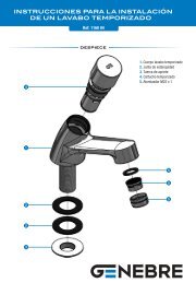
INSTRUCTIONS FOR MONOBLOC FILTERENGLISHRead this manual thoroughly before installing the <strong>filter</strong> and carefully follow the instructions during installation and use.Keep this manual for future reference regarding the operation of this apparatus.SAFETY INSTRUCTIONS. READ CAREFULLY? All electrical installations should comply with the following standard;NF C15-100NF EN 60-335-2-41that refers “to the construction of electrical installations, both in indoor and outdoor swimming pools”, or the equivalentstandard in force in each region or country.? All <strong>filter</strong>ing should follow the C 15-100 installation standard that stipulates that all electrical apparatus located at lessthan 3.5 m. from the pool and freely accessible, should be supplied by a very low voltage of 12 V. All apparatussupplied with 220 V should be located at least 3.5 m. from the swimming pool edge. Ask the manufacturer forpermission to make any modifications in one or more elements of the <strong>filter</strong>ing system.? The electrical installation should be performed by professional staff qualified in electrical installations.? The height of the sand should not exceed 2/3 of the height of the tank.? The apparatus must not be on while the pool is being used.? Do not operate the apparatus unless it is properly primed.? NEVER touch the <strong>filter</strong> when it is operating if you are wet or have wet hands.? When handling the <strong>filter</strong> or valve, DISCONNECT the power supply.? Make sure that the ground is dry before touching the electrical equipment.? Do not install the <strong>filter</strong> where it could become wet, as it may cause electrocution.? Do not allow children or adults to lean against or sit on the apparatus.? If the supply flex of the apparatus is damaged, it should be replaced. Read the instructions carefully to replace it.If in doubt, contact the technical service.1 INSTRUCTIONS FOR MONOBLOC FILTERThe <strong>filter</strong> which you have just purchased is a device which is especially planned and designed for elevated pools. As aresult of its innovative design and high level of functionality, it provides you with the different components required to <strong>filter</strong>water: <strong>filter</strong>, pump and selector valve in a single unit. The main components of this <strong>filter</strong> are as follows:Fig Pos Name1 1 Filter1 2 Pump1 3 selector valve1 4 Protective housing1 5 Drain plug1 6 Ventilation covers1 7 Electric power cable1.1 REQUIREMENTS FOR CORRECT INSTALLATIONThis apparatus is easy to install and can be assembled by one adult in about 2 HOURS, taking care to correctly follow theinstructions detailed in this manual.Only the following tools are required to correctly handle the <strong>filter</strong> components and to install it.Task Tool Alternative toolTighten the hose flanges 7mm Stecker screwdriver Philips screwdriverCut the liner Cutter KnifeProtection of collector pipe Piece of plastic Piece of fabric2 BEFORE CONNECTING THE FILTER2.1 LocationPlace the <strong>filter</strong> on a flat, solid surface at a minimum distance of 3.5 metres from the pool (in accordance with standard NFC15-100 or the equivalent standard of the region or country) and at the same level as the bottom of the pool to prevent air
from entering the cleansing circuit and the <strong>filter</strong> from becoming unprimed (Fig. 2). The <strong>filter</strong> should be protected from sunand rain, and kept it in an area with sufficient ventilation during operation. Never cover it during operation.2.2 AssemblyBefore assembling the <strong>filter</strong>, assemble the skimmer, following the instructions provided with the skimmer or the swimmingpool.After the <strong>filter</strong> has been set into place, proceed as follows:? Loosen the screw on the metal band or seal which joins the valve to the <strong>filter</strong> (Fig.4).? Remove the TOP selector valve and cover the opening of the inner collector tube with protective plastic in order toprevent sand from entering the tube (Fig.5).? Place the inner collector properly on the bottom of the <strong>filter</strong> (Fig.6).? Insert the sand (25 kg), NO SUPPLIED, inside the <strong>filter</strong>. The silica sand lasts for an unlimited period of time. It shouldonly be replaced if lost. Record the reference for the level of silica sand for future replacement.? Eliminate the remains of sand from the <strong>filter</strong> opening and remove the protective plastic.? Replace the TOP selector valve with its coupling and secure with the metal band or seal .? Tighten firmly the screw on the metal band which joins the valve to the <strong>filter</strong> (Fig.4).? Connect the suction and discharge hoses to the suction and discharge terminals on the valve, tightening them firmlywith the clamps (Fig.7).? Insert the Teflon supplied on the thread of the skimmer terminal and connect the other end of the suction hose.Tighten firmly with a clamp. Repeat the same procedure with the feedback nozzle terminal and connect the dischargehose.? Following installation, the first cycle of <strong>filter</strong> backwash should be performed. In order to do so, follow the instructions inthe section 5.3.3 ELECTRIC CONNECTIONAll electrical installations should comply with the following standard:NF C15-100NF EN 60-335-2-41that refers “to the construction of electrical installations, both in indoor and outdoor swimming pools”, or theequivalent standard in force in each region or country.The pump must be connected to a 220/230 V. alternating current and 50 Hz power point, with earth connection.Consumption: 240 W.An omnipolar switch must be used to ensure there is no power feed to the <strong>filter</strong> when it is not in use. A 30 mA differentialmust also be used to protect from electrical breakdowns. (Not supplied. These items can be purchased at electricityshops.)4 TOP SELECTOR VALVEThe top selector valve on the <strong>filter</strong> is used to select the 4 different <strong>filter</strong> functions: filtration (FILTER), backwash, waste andclosed. To change the valve setting, proceed as follows:? Always disconnect the socket.? Loosen the upper triangular knob on the valve by turning it until you can lift the cover of the housing and turn it.? Turn the cover until the desired setting is aligned with the return hose, where the anchorage is, and the rib is inserted inits housing (see fig. 12).? Retighten the knob by turning it, but be careful not to overtighten as the internal components of the valve may bedamaged.5 OPERATIONThe operation of this <strong>filter</strong> is based on the filtration capacity of the silica sand which is inside. The water in the pool isdriven by the <strong>filter</strong> pump and forced to pass through the silica sand. The sand acts as a <strong>filter</strong>ing element which retains theimpurities in the water. The environment, trees, pollen, insects and frequency of bathing, as well as other factors,determine the dirtiness of the water in the pool. Depending on the dirtiness, the silica sand in the <strong>filter</strong> should be cleanedwith greater or less frequency (see section 5.3).To maintain the pool water in good condition, use the chemical products recommended by the manufacturer (chlorine,alga protection, etc.).THE CHEMICAL PRODUCT SHOULD NEVER BE PLACED IN THE BASKET OR THROUGH THE FILTER, THISWOULD DETERIORATE THE MATERIALS OF THE UNIT AND LIMIT ITS EFFICACY.5.1 Priming the <strong>filter</strong>The <strong>filter</strong> must be correctly primed at all times. If the <strong>filter</strong> is not primed this means that an air chamber has been createdinside which causes defective circulation of water. This fact prevents proper filtration of the water by the silica sand and isdetrimental to the motor.The <strong>filter</strong> may become unprimed for several reasons: