User Manual (Ita-Eng) - Setec
User Manual (Ita-Eng) - Setec
User Manual (Ita-Eng) - Setec
- No tags were found...

You also want an ePaper? Increase the reach of your titles
YUMPU automatically turns print PDFs into web optimized ePapers that Google loves.
MANUALE USO E MANUTENZIONEUSE AND MAINTENANCE MANUALATTUATORI MECCANICIMECHANICAL ACTUATORSISO 15552 : 2004ISOMOVECert. n° EMS-2240/S
www.setec-group.it1
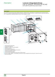
<strong>Manual</strong>e uso e manutenzione ISOMOVEISOMOVE use and maintenanceISOMOVE MODULO BASE - ISOMOVE BASIC MODULEVersione con chiocciola flangiataFlanged nut releaseTappo a tassello mobile per ingrassaggioSliding plug for lubricationVersione con chiocciola filettataThreaded nut releaseTappo filettato per ingrassaggioScrew plug for lubricationVersione antirotazione in materiale plasticoAntirotation rod in plastic material releaseAntirotazione in bronzoBronze antirotation rodFig. 1P / N PZ DESCRIZIONE DESCRIPTIONPcs1 1 TESTATA ANTERIORE FRONT HEAD2 1 TESTATA POSTERIORE REAR HEAD3 1 CAMICIA ISOMOVE CYLINDER4 1 ATTACCO FILETTATO SCREW CAP5 1 STELO EXTENSION ROD6 1 VITONE BALLSCREW7 1 ROTELLA ROLLER8 1 PISTONE PISTON9 1 ASTA ANTIROTAZIONE ANTIROTATION ROD9B - VITI SCREWS10 8 VITE TCCE SCREW TCCE11 1 CUSCINETTO BEARING12 1 GHIERA AUTOBLOCCANTE SELF-LOCKING NUT13 1 FASCIA DI GUIDA MERKEL GUIDING LINER MERKEL14 1 ANELLO MAGNETICO MAGNETIC RING15 2 GRANO UNI 5923 GRUB SCREW16 1 CHIOCCIOLA TIPO FILETTATO THREADED NUT16 1 CHIOCCIOLA TIPO FLANGIATO FLANGED NUT17 1 VITE 097F SCREW 0.97 F18 1 TAPPO TCEI SCREW PLUGTASSELLO SCORREVOLE SLIDING BOSS19 1 BOCCOLA BUSHING20 1 RASCHIATORE SCRAPERwww.setec-group.it2
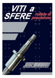
ISOMOVE VERSIONE “D” / ISOMOVE “D” VERSIONP / N PZ DESCRIZIONE DESCRIPTIONPcs00 1 ISOMOVE BASE ISOMOVE BASIC MODULE21 1 DISTANZIALE SPACER22 1 FLANGIA MOTORE MOTOR FLANGE23 4 VITE TSEI TSEI SCREW24 1 MOTORE MOTOR25 4 VITE TCEI TCEI SCREW26 1 GIUNTO SERVO COUPLING27 1 FLANGIA BLOCCAGGIO BEARING COUPLINGCUSCINETTOFLANGE28 1 TAPPO TCEI TASSELLO SCREW PLUGSCORREVOLESLIDING BOSS28B 1 VITE SCREW29 1 TAPPO A PRESSIONE CAPTappo filettatoper bloccaggio giuntoThread stopperfor coupling locking screwFig. 2Versione con tappo a tassellomobile per bloccaggio giuntoSliding plug for servo-couplinglocking screwP / N PZ DESCRIZIONE DESCRIPTIONPcs00 1 ISOMOVE BASE ISOMOVE BASIC MODULE21 1 FLANGIA MOTORE MOTOR FLANGE22 1 CARTER CASING23 1 PULEGGIA VITE SCREW PULLEY24 1 CALETTATORE SHRINK DISC25 1 CINGHIA DENTATA TOOTHED BELT26 4 VITE TCEI SCREW TCEI27 4 VITE TCEI SCREW TCEI28 2 VITE TCEI SCREW TCEI29 1 MOTORE MOTOR30 4 VITE TCEI SCREW TCEI31 4 ROSETTA DI SICUREZZA WASHER32 6 ROSETTA DI SICUREZZA WASHER33 1 CALETTATORE SHRINK DISC34 1 PULEGGIA PULLEY35 2 PANNELLO LATERALE SIDE PANEL36 8 VITE TSEI SCREW TSEIISOMOVE VERSIONE “R” / ISOMOVE “R” VERSIONFig. 3www.setec-group.it3
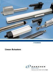
<strong>Manual</strong>e uso e manutenzione ISOMOVE / ISOMOVE use and maintenanceIDENTIFICAZIONESu ogni prodotto è applicata una targhetta identificativa che riporta iprincipali dati che lo caratterizzano:ACTUATOR DESIGNATIONIn every product there is a plate with all the main info about theproduct you have purchased:www.setec-group.it - T. +39.011.4518611Code N° IM–050–05–0050–R–S48Drw N° I–0050–0000–000–0050Order N° XXXXXXXSerial N° XXXXXXFig. 4CODE: IM (ISOMOVE) – O5O (TIPO) – 05 (PASSO VITE) – 0050(CORSA) – R (POSIZIONE MOTORE ➝ R = RINVIATO, D = DIRETTO) –S48 (TIPO MOTORE).In caso di assistenza siete pregati di annotare ciascun dato inmodo da identificare il prodotto in oggetto.Fig. 4CODE: IM (ISOMOVE) – O5O (SIZE) – 05 (SCREW LEAD) – 0050 (STROKE)– R (MOTOR POSITION ➝ R = BELT GEAR VERSION, D = IN LINEVERSION) – S48 (MOTOR TYPE)If you need assistance, you are pleased to send us every data tolet us identify the product.4.1.0 TIPOLOGIA DI IMPIEGO4.1.1 Temperatura di lavoro: - 20°C; +70°C4.1.2 Grado di protezione IP: tutti gli attuatori standard sono realizzaticon grado di protezione IP54 a condizione che il motore elettricoraggiunga tale grado di protezione.4.1.3 Intermittenza di lavoro: tutti gli attuatori standard garantisconole prestazioni nominali indicate nel nostro catalogo in assenzadi urti e di vibrazioni, con carichi esclusivamente di tipo assialee una temperatura ambiente di 40°C.Per condizioni differenti contattare il nostro servizio tecnico.4.1.4 NORMATIVETutti i prodotti SETEC sono costruiti in accordo alla normativaCEE sulle macchine. come componenti di macchine i nostriattuatori possono essere installati solo su macchinari concaratteristiche rispondenti alla normativa comunitaria sullemacchine secondo le seguenti:EN 292-1, EN 2.1991, EN 954-1, EN 294.1992,EN 349.1993, EN 418.1992In caso di installazione dei nostri prodotti su macchinari chenon seguono le normative di legge, la SETEC non garantisce supossibili danni arrecati agli attuatori o per l’incolumità deglioperatori.4.2.0 INSTALLAZIONEN.B. PRIMA DI RENDERE OPERATIVA LA MACCHINA OCCORRELEGGERE ATTENTAMENTE IL SEGUENTE MANUALE ESEGUIRNE LE INDICAZIONI RIPORTATE; TENERE LA SEGUENTEPUBBLICAZIONE E TUTTI I DOCUMENTI A CUI SI FA RIFERIMENTOIN LUOGO ACCESSIBILE A CIASCUN OPERATORE E AL PERSONALEDI MANUTENZIONE. LA SETEC SI RISERVA IL DIRITTO DI NONPROVVEDERE ALLA RIPARAZIONE O ALLA SOSTITUZIONE IN4.1.0 OPERATING ENVIRONMENT4.1.1 Operating temperature: - 20°C; +70°C4.1.2 IP rating: all standard actuators are made in IP54 rating inagreement as the standard electric motors.4.1.3 Duty cicle: all standard actuators guarantee the nominalperformance indicated in our catalogue, in absence of impactsand vibrations, with purely axial forces and an environmenttemperature of 40°C. Contact our technical service for differentconditions.4.1.4 COMMUNITARY RULESAll SETEC products are realized according to CEE rules aboutmachines; as machine elements, our actuators can be usedonly inside machines in accordance with the followingsCEE rules:EN 292-1, EN 2.1991, EN 954-1, EN 294.1992,EN 349.1993, EN 418.1992If our actuators are used inside equipments not according therules above, SETEC doesn’t garantee for possible damages orthe safety of the operators.4.2.0 INSTALLATIONBEFORE STARTING THE MACHINERY, USERS MUST READ THEFOLLOWING MAUAL; KEEP THIS AND ALL THE RELATED DOCUMENTSIN AN A PLACE ACCESSIBLE TO THE MAINTENANCE STAFF.SETEC COULD ASSERT THE RIGHT NOT TO REPAIR OR TO REPLACEUNDER WARRANTY WHEN DAMAGES ARE DUE TO UNCORRECTUSE OF THE ACTUATORS OR WRONG MAINTENANCE.www.setec-group.it4
GARANZIA DEI NOSTRI PRODOTTI IN CASO DI DANNI DOVUTI A UNNON CORRETTO UTILIZZO DELL’ATTUATORE E/O A UNA ERRATAMANUTENZIONE. Per qualunque altra informazione vi rimandiamoalla consultazione del catalogo SETEC specifico che rappresenta parteintegrante dello stesso.4.3.0 CONTROLLI PRECAUZIONALI ALL’AVVIO4.3.1 Tutti i nostri prodotti sono accuratamente controllati prima dellaspedizione, tuttavia si richiede a scopo precauzionale diverificare possibili impedimenti al movimento degli organi internio il serraggio delle viti delle testate.4.3.2 Accertarsi che la struttura su cui è montato l’attuatore sia ingrado di sopportare il carico massimo previsto senza subiredelle deformazioni che comprometterebbero il funzionamentodell’elettrocilindro.4.3.3 N.B. I nostri attuatori sono progettati per movimentare carichinella sola componente assiale e un carico radiale, seppur dipiccola entità, o un carico disassato potrebbero comprometterel’affidabilità e la durata utile del gruppo vite a ricircolo-chiocciola.4.3.4 Provvedere alla pulizia dell’attuatore e nello specifico dello steloper evitare che impurità possano penetrare all’interno del sistema,utilizzando prodotti idonei che non intacchino i trattamentisuperficiali dei materiali. (I nostri attuatori prevedono l’utilizzodi un raschiapolvere che, a seconda della grandezza, può essereinterno o esterno). Polvere e abrasivi potrebbero accelerarel’usura degli organi in movimento.4.3.5 I nostri attuatori sono forniti di tappi filettati (Fig.1-18) o,a seconda del modello, tasselli mobili impiegati per tappare ilforo ricavato sulla camicia del cilindro da utilizzare per lalubrificazione. Verificare il corretto serraggio per impedire lafuoriuscita di grasso lubrificante o l’ingresso di impurità nelsistema.4.3.6 È indispensabile al fine di salvaguardare la duratadell’elettrocilindro evitare qualsiasi urto e/o forti vibrazioni alsistema; è infatti risaputo che le viti a ricircolo di sfere e gli stessicuscinetti subiscono forti stress meccanici in caso di urtosoprattutto a cilindro fermo.4.3.7 Evitare di superare i limiti di carico nominale dichiarato perevitare gravi danni al sistema, durate fortemente ridotte edeformazioni permanenti che pregiudicherebbero la funzionalitàdell’attuatore.A tal scopo è buona norma, in caso di utilizzo di motoribrushless, prevedere un controllo sui picchi di coppia (fino a 5volte il valore nominale) tipiche di questo tipo di motorizzazione.Superare i limiti di coppia nominale in ingresso all’attuatorepotrebbe determinare gravi danni al sistema e pregiudicarne lavita utile.4.3.8 Non portare mai l’attuatore a battuta meccanica!4.3.9 In caso di applicazioni in cui la traslazione è lungo l’asse verticaleoccorre prevedere un sistema frenante che mantenga fermo ilcarico quando il motore è spento. Il sistema vite a ricircolo- chiocciolaè infatti un sistema reversibile dote intrinseca dovuta alla bassissimacondizione di attrito interno.4.3.10 Negli elettocilindri con motorizzazione rinviata la trasmissionedel moto avviene mediante cinghia dentata senza gioco in poliuretanocon rinforzi in acciaio per impedirne l’allungamento. Il tensionamentodella cinghia è predeterminato da un interasse fisso tra le puleggeper cui non è previsto alcun tipo di tenditore.Qualora sia indispensabile provvedere alla sostituzione dellacinghia in caso di gioco eccessivo, vi rimandiamo alla lettura delFor any other information, consult the specific catalogue SETEC“ISOMOVE” that is an integral part of this manual.4.3.0 STARTING CHECKS4.3.1 All SETEC products are carefully tested before delivery; forprecautionary measure, it’s important to verify that the objectrotates freely and the correct locking of screws of the twoheads of the actuator.4.3.2 Ensure that the structure the actuator is mounted on issufficiently strong to stand the maximum load withouthaving any deformation which could affect the good operationof the actuator.4.3.3 Our actuators are realized to stand only axial forces; radial ornot aligned forces could compromise the proper operation andthe reliability of the product and reduce is the its lifetime.4.3.4 Clean the actuator and the extension rod to avoid that impuritymay enter, using the right products not to corrode the surfaceof the materials. (Our actuators have inside, or outside accordingto the dimension, a scraper ring). Dust and abrasives mayaccelerate the wear of inner components.4.3.5 Our actuators are supplied with screw plugs (Fig.1-18) orsliding boss (depending on the model) to plug the hole usedfor the lubrication of the ballscrew. Verify the correct tighteningto avoid the grease to go out or impurity to go in.4.3.6 To safeguard the life time of the actuator it’s very important tokeep off any impact and vibration; it’s well-known that ballscrews and bearings are strongly stressed by impacts particularlywhen the actuator is motionless.4.3.7 Never exceed the limits of the nominal load stated in order toavoid serious damage to the system, strongly reduced life timeand permanent deformations that could compromise theproper operation of the actuator.According to what has been written above, when a brushlessmotor is used, you must limit torque peaks.4.3.8 Never use the actuator inner parts as mechanical shoulder!4.3.9 When the actuator is used in application in which the loadis moved along the vertical axis it’s necessary to provide theactuator with a brake that stops the load when the motor is off;it’s due to the reversibility of the ballscrew.4.3.10 In belt gear actuators, it’s used a V-belt zero backlash polyurethanesteel reinforced belt to avoid its elongation. The tension of the beltis stated by a fixed pulleys’ wheelbase, so no tensioning system isthere. If it’s necessary to change the belt when backlash due to wearis there; in this case we ask you to read the following pages relatedto assembling and disassembling operations.4.3.11 “Antirotation device” is used to let the extension rod movewithout rotation, when there’s no external guiding.To avoid the rotation of the inner group (nut - piston - extensionrod) that would forbid the ballscrew to transform the rotarymovement in a linear one, it’s available the antirotation device.It’s clear that, as a consequence, the antirotation device isdesigned to stand very low torques so it mustn’t be used tostand external torques.When the translation of the load generates torques along themovement’s axis it’s good that external systems could be ableto neutralize them to avoid the deformation of the extension rodthat would compromise the proper operation of the actuator.www.setec-group.it5
<strong>Manual</strong>e uso e manutenzione ISOMOVE / ISOMOVE use and maintenancecapitolo specifico sul montaggio e smontaggio dell’attuatore.4.3.11 Il sistema opzionale “antirotazione” è utilizzato per permetterela fuoriuscita dello stelo anche in quelle condizioni di assenza dicontrasto esterno.Al fine proprio di evitare la rotazione dell’intero gruppo mobile(chiocciola-pistone-stelo), che impedirebbe la trasformazionedel moto mediante il sistema a vite da rotatorio a traslatorio,viene utilizzata l’antirotazione. Si evince come la coppia chedeve sopportare sia di bassissima entità per cui non può esserein nessun modo utilizzata per vincere delle coppie esterneanche lievi. Nei casi in cui, per effetto della traslazione del carico,possano generarsi delle coppie lungo l’asse del moto èindispensabile che vengano neutralizzate da sistemi esterniall’attuatore per evitare deformazioni dell’asta antirotazione chepregiudicherebbero il corretto funzionamento dell’attuatore.(Per le tipologie di antirotazione disponibili Vi rimandiamo alladescrizione generale del sistema).4.3.12 Non ruotare mai lo stelo nelle versioni in cui è presente il sistemaantirotazione per non danneggiare l’attuatore.4.4.0 MONTAGGIO DEL MOTORE NELLA VERSIONE“R” RINVIATA (Fig. 3)4.4.1 Svitare le viti (28).4.4.2 Togliere il carter (22).4.4.3 Posizionare e avvitare il motore (29) tramite le viti (30).4.4.4 Calzare la cinghia (25) sulle pulegge (23) (34) con inseriti icalettatori (24) e (33).4.4.5 Inserire contemporaneamente la puleggia (23) sull’albero del motore ela puleggia (34) sull’estremità della vite a ricircolo (06) [Fig. 1].4.4.6 Bloccare i calettatori (24) e (35) secondo la tabella “C” relativaai calettatori (per la tipologia del calettatore verificare le dimensioni).4.4.7 Controllare il perfetto parallelismo e allineamento delle pulegge.4.4.8 Riposizionare il carter (22).4.4.9 Inserire e bloccare le viti (28).4.5.0 MONTAGGIO DEL MOTORE NELLA VERSIONE“D” DIRETTA (Fig. 2)4.5.1 Posizionare il giunto (26) sull’alberino del motore (24) verificandoche la posizione assiale del giunto, una volta accoppiato almotore ed inserito nella campana (22), sia tale da permettere ilraggiungimento della apposita vite di bloccaggio del giuntostesso tramite il foro ricavato sul distanziale (21).4.5.2 Sfilare il motore (24) e serrare il giunto (26) sull’albero del motoreagendo sulla vite apposita, rispettando le coppie di serraggio riportatenella tabella “D”. (Per la tipologia del giunto, verificare la siglariportata sul giunto stesso).4.5.3 Posizionare il motore (24) completo di giunto (26) sulla campana (22)e bloccare il medesimo con le viti (25).4.5.4 Bloccare il giunto (26) sulla vite a ricircolo (06) [Fig. 1] ,facendoriferimento alla tabella “D”, mediante il foro presente sul distanziale (21).4.5.5 Tappare il foro sul distanziale (21) mediante il tappo (28) che, aseconda del modello, potrà essere filettato o a tassello mobile.(For types of antirotation device you are asked to see thegeneral description of the actuator).4.3.12 Never rotate the extension rod when the antirotationdevice is there not to damage the actuator!4.4.0 MOUNTING MOTORS IN BELT GEARVERSION “R” (Fig. 3)4.4.1 Unscrew screws (28).4.4.2 Remove casing (22).4.4.3 Put in position the motor and screw it (29) using screws (30).4.4.4 Set the belt (25) on pulleys (23) (34) with sleeves inside (24)and (33).4.4.5 Insert at the same time the pulley (23) on motor shaft andthe pulley (34) on the back of the ballscrew (06) [Fig. 1].4.4.6 Lock the shrink disc (24) and (35) according to the Tab “C” aboutshrink disc (check sleeves’ type seeing the identification plate).4.4.7 Check the perfect alignment and parallelism of pulleys’ axis.4.4.8 Position the casing (22).4.4.9 Insert and block screws (28).4.5.0 MOUNTING MOTORS IN LINEVERSION “D” (Fig. 2)4.5.1 Put in position the servo coupling (26) on motor shaft (24)verifying that axial servo coupling position, once joined to themotor and inserted in the flange (22), permits to reach the lockingscrew of the servo coupling through the hole in spacer (21).4.5.2 Pull out the motor (24) and tighten the servo coupling’sscrew (26) on motor’s shaft, according to the Tab “D”.(Check servo coupling’s type seeing identification plate).4.5.3 Position motor (24) with servo coupling in (26), on flange (22)and lock it with screws (25).4.5.4 Grip servo coupling (26) to the ballscrew (06) [Fig. 1],according to the Tab “D”, through the hole in spacer (21).4.5.5 Plug the hole in spacer (21) using the screw plug (28) that,on the base of the model, would be made as a sliding boss too.4.6.0 ORDINARY MAINTENANCE AND SCHEDULEDCONTROLS4.6.1 A suitable maintenance with a correct use avoids problemsin terms of reliability and safety, furthermore it guaranteesfunctionality and quality through the product life; so we askyou to have a scrupulous care of scheduled maintenance inthe summarizing tab below (Tab. “A”).4.6.0 MANUTENZIONE ORDINARIA E CONTROLLI PERIODICII4.6.1 Una buona manutenzione del sistema, insieme ad un corretto utilizzo,evitano problemi legati all’affidabilità e alla sicurezza garantendonefunzionalità e qualità nel tempo, per cui vi chiediamo di seguirescrupolosamente gli interventi di manutenzione programmatariassunti nella tabella di seguito (Tab. “A”):www.setec-group.it6
INTERVALLO PARTICOLARE INTERVENTO Rif.FREQUENCY PART TYPE CHECK Ref.Dopo 2 MESI dall'installazione2 months after installationEntro 6 mesiWithin 6 months500 ore / hours12-18 MESIEvery 12-18 MONTHS12 / 18 MESIEvery 12 / 18 MONTHS12 / 18 MESIEvery 12 / 18 MONTHS12 / 18 MESIEvery 12 / 18 MONTHSVITI TESTATE CONTROLLO SERRAGGIO montaggio - manuale d'usoHEAD SCREWS TIGHTEN SCREWS mounting - use guideVITE A RICIRCOLO LUBRIFICAZIONE / LUBRICATION Manutenzione - manuale d'uso / Maintenance - use guideBALLSCREWS GIOCO CHIOCCIOLA / NUT BACKLASH Catalogo VITI a sfere SETEC / SETEC ballscrew catalogueGIUNTO / SERVO COUPLING CONTROLLO SERRAGGIO / TIGHTEN SCREWS Montaggio - manuale d'uso / Mounting - use guideCALETTATORI / SHRINK DISCS CONTROLLO SERRAGGIO / TIGHTEN SCREWS Montaggio - manuale d'uso / Mounting - use guideCINGHIA DENTATAI / V BELT CONTROLLO GIOCO / CHECK BACKLASH Manutenzione - manuale d'uso / Maintenance - use guidePULEGGIA / PULLEY VERIFICA ALLINEAMENTO / CHECK ALIGNMENT Controlli all'avvio - manuale d'uso / Starting check - use guide* In condizioni di carico e di utilizzo gravosi dimezzare gli intervalli di manutenzione dichiarati.* In case * In of heavy heavy load load and and use heavy condition conditions double halve the frequency the frequency of planned of planned maintenance. maintenance.Tab. “ A”4.6.2 CONTROLLO SERRAGGIO:4.6.2.1 VITI DI FISSAGGIO TESTATE: verificare il serraggio delle vitimediante bussola specifica; in caso di condizioni gravose e conforti vibrazioni intensificarne il controllo (per le coppie diserraggio vedere Tab. “B”);4.6.2.2 GHIERA AUTOBLOCCANTE: la ghiera per il blocco del cuscinettoha il compito di vincolare assialmente la vite. L’insorgenza digioco, dovuto a condizioni anomale di funzionamento, potrebbepregiudicare la durata del cuscinetto e la precisione di posizionamentodell’attuatore. Per l’accesso alla ghiera vi rimandiamo al capitolo“montaggio e smontaggio”.4.6.2.3 GIUNTO DI TRASMISSIONE: il giunto ha il compito di trasmettereil moto in caso di motorizzazione “D” diretta tra l’albero motoree la vite a ricircolo. I giunti utilizzati sono del tipo a gioco zero eadottano un collegamento a morsetto.Per evitare slittamenti che pregiudicherebbero la precisione diposizionamento dell’attuatore occorre verificare periodicamenteil serraggio utilizzando chiavi dinamometriche (le coppie sonoriportate nella tabella “D”).Per la tipologia di giunto vedere la sigla riportata sul giuntostesso. Per l’accesso al giunto vi rimandiamo al capitolo“montaggio e smontaggio“.4.6.2.4 CALETTATORE: il calettatore ha il compito di bloccare le puleggesul relativo albero, assicurarsi quindi che lo stesso sia sempreben bloccato. Le coppie di serraggio sono riportate nella Tab.“C”. Per la tipologia di calettatore vedere le dimensioni dellostesso. Per l’accesso ai calettatori vi rimandiamo al capitolo“montaggio e smontaggio”.4.6.2.5 Gli attuatori vengono forniti con sistema di bloccaggio dei filettidelle viti di serraggio (Loctite morbida); nel caso di acquisto diattuatori in versione custom, per consentire il montaggio delmotore, alcune viti non vengono bloccate.Tab. “A”4.6.2 SCREW TIGHTENING CHECK:4.6.2.1 HEAD SCREWS:verify screw tightening using the specific tool;in heavy load applications, or in presence of vibrations, intensifythe control (see Tab. “B”).4.6.2.2 SELFLOCKING NUT: the selflocking nut has the task to axiallyconstrain the ballscrew. The birth of backlash, due to abnormalworking conditions, could reduce the life time of bearings andthe correct actuator’s positioning accuracy.To get to the self locking nut, see the “mounting anddisassembling” chapter.4.6.2.3 SERVO COUPLING: the servo coupling is used to transmit thepower, in “D” ISOMOVE version, between motor shaft andballscrew.The coupling is “zero” backlash type; to avoid sleeperycondition that could create a bad positioning, it’s important tocheck the tightening of its locking screw through a dynamometrickey (see Tab “D” for tightening torque). Check servo coupling’stype seeing identification plate. To get to the servo coupling,see the “mounting and disassembling” chapter.4.6.2.4 SHRINK DISC: it has the task to lock the pulley on relative shaft, besure that it is always locked (see Tab “C” for tightening torque).Check servo coupling’s type seeing identification plate.To get to the servo coupling, see the “mounting and disassembling”chapter.4.6.2.5 In our actuators all the screws are blocked using the “LOCTITE”thread locking system; when a custom actuator is bought, toallow motor installation some screws aren’t locked.Once the motor mounted, we suggest you to apply the LOCTITEsystem.www.setec-group.it7
<strong>Manual</strong>e uso e manutenzione ISOMOVE / ISOMOVE use and maintenanceSi consiglia, una volta effettuato il montaggio, di applicare dellaLoctite morbida. Più in generale di seguito vengono allegate le tabellerelative alle norme sul serraggio; la seguente norma stabilisce i valoridella coppia nominale e relative tolleranze da applicare per il serraggiodella bulloneria in funzione delle applicazioni. Per la scelta delle classidi serraggio, consultare la Tab.B1 e definire il bullone da utilizzare,riportato in Tab.B2, considerando le forze di trazione di ogni singolobullone (Tab. B3).In the tabs below you can find the values of tightening torque of thescrews according to the Community rules; the following rule setstorque and tolerance values to apply for tightening screws on thebase of applications.To choose the tightening class, consult Tab. B1 and define thescrew to use, seeing Tab B2, according to the strength of everyscrew (Tab B3)Classe di serraggioTightening classApplicazioniApplicationsTolleranze riferite alla coppia funzionaleTolerances according to nominal torqueIMOLTO IMPEGNATIVEVERY HEAVY± 5 %IIIMPEGNATIVEHEAVY5%-15%IIIPOCO IMPEGNATIVENOT HEAVY5%-35%Tab. “B1”[Nm]FilettaturaTHREADApertura chiavedella vite e/o del dadoScrew’s toolCLASSE DI SERRAGGIO / TIGHTENING CLASSIII II ICLASSE DI RESISTENZA DELLA VITE / SCREW STRENGHT CLASS8,8 10,9 12,9CLASSE DI RESISTENZA DEL DADO / NUT STRENGHT CLASS8 10 12M4 7 2,3 3,3 4M5 8 4,8 6,8 8M6 10 8 11,2 13,6M8 13 20 28 32,8M10 17 39,2 55,2 66,4M12 19 68,8 96 116M14 22 108 152 184M16 24 168 236 284M18 27 232 324 388M20 30 328 464 552M22 32 440 624 744M24 36 568 800 960M27 41 840 1200 1440M30 46 1160 1600 1920Tab. “B2”Coppia diserraggioTighteningtorqueM4 7 3120 4360 5240M5 8 5080 7160 8560M6 10 7200 10080 12080M8 13 13200 18560 22320M10 17 20960 29520 35440M12 19 30640 TABELLA b1 b2 43200 b351600M14 22 42000 59200 70800M16 24 58400 81600 98400TABELLA B! B” B£M18 27 70400 99200 118400M20 30 91200 128000 153600M22 32 112800 159200 191200M24 36 131200 184000 220800M27 41 172000 241600 290400M30 46 209600 294400 253600[N]Tab. “B3”Forzadi trazioneAxialstrenghtwww.setec-group.it8
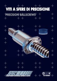
4.6.3 CONTROLLO GIOCHI4.6.3.1 CUSCINETTO: il cuscinetto impiegato è del tipo a gioco ”zero”a doppio contatto obliquo, tuttavia in condizioni di funzionamentogravose è opportuno verificare il gioco assiale per non avereerrori di posizionamento dell’attuatore e una rapida usura delcomponente. Qualora si siano verificati dei giochi procederealla sostituzione del cuscinetto stesso.Per l’accesso al cuscinetto vi rimandiamo al capitolo“ montaggio e smontaggio “ .4.6.3.2 CINGHIA DENTATA: non è prevista la possibilità di regolare iltensionamento della cinghia; se in condizioni particolari dovesseverificarsi un allungamento della cinghia provvedere allasostituzione. Per l’accesso alla cinghia vi rimandiamo al capitolo“montaggio e smontaggio”.4.6.3.3 VITE A RICIRCOLO / CHIOCCIOLA: la chiocciola viene fornitasempre con gioco assiale il cui valore è dichiarato nel catalogoSETEC (viti a ricircolo di sfere). Qualora in condizioni particolariil gioco assiale dovesse superare il valore massimo nominaleoccorre sostituire il sistema vite/chiocciola per non incorrere inerrori di posizionamento.4.6.4 LUBRIFICAZIONE4.6.4.1 L’attuatore viene fornito con la vite a ricircolo completamentelubrificata; essendo il sistema totalmente sigillato, la fase dilubrificazione può avvenire ad intervalli piuttosto ampi (vedipar. 4.6 Tab. “A” ), tuttavia una periodica lubrificazione contribuiscea limitare la rumorosità, ridurre le coppie d’attrito e quindi ilcalore generato. I lubrificanti impiegabili sono i medesimi utilizzatiper la lubrificazione dei cuscinetti.4.6.4.2 La lubrificazione è del tipo manuale e può avvenire introducendodirettamente un ugello all’interno della camicia dell’attuatore ederogando il lubrificante direttamente sulla vite; per questaoperazione occorre far riferimento alla seguente procedura(vedi Fig. 5 per schema di lubrificazione):4.6.4.2.1 far fuoriuscire lo stelo (05) fino a fondo corsa in modo da averlibero accesso alla vite (06).4.6.4.2.2 svitare il tappo (18) o la vite del tassello mobile laddove previsto.4.6.4.2.3 introdurre l’ugello attraverso il foro sulla camicia (03)dell’attuatore fino a raggiungere la vite (06).4.6.4.3 Evitare di introdurre quantità eccessive di grasso per nonpregiudicare il corretto funzionamento dell’attuatore.4.6.3 BACKLASH CHECK4.6.3.1 BEARINGS: the bearings used in our actuators are angularcontact double rows “zero” backlash type; in heavy workingcondition it’s important to control the axial backlash to avoidpositioning errors of the actuator and a quick wear of thecomponent.To get to the bearing , see the “mounting and disassembling”chapter.4.6.3.2 V-BELT: it’s not available a tensioning system; change thebelt if its length should abnormally increase. To the access tothe v-belt , see the “ mounting and disassembling “ chapter.4.6.3.3 BALLSCREW / NUT: the standard nut is with axial backlash;you can find the value of the backlash in the SETEC ballscrewcatalogue. If, in particular working condition, the backlashshould exceed the maximum nominal value it is necessary toreplace the ballscrew not to have positioning errors.4.6.4 LUBRICATION4.6.4.1 Before delivering, the ballscrew of the actuator is completelylubricated; as it is totally sealed, the lubrication can be madewith a low frequency (see Par.6 Tab. “A”), however a recurringlubrication may reduce noise, friction torques and then heatgeneration.4.6.4.2 The lubrication can be realized by hand introducing the nozzleinto the cylinder and distributing the grease directly on screw;to do that, see the following procedure (see Fig. 5 below):4.6.4.2.1 the extension rod (05) up to stroke end (06).4.6.4.2.2 unscrew plug (18) or the screw of the sliding boss whereprovided.4.6.4.2.3 introduce the nozzle through the hole in the cylinder (03)to reach the ballscrew (06).4.6.4.3 In order not to damage the actuator, do not put in a quantityof grease bigger than the required value.SCHEMA DI LUBRIFICAZIONE ISOMOVE / ISOMOVE LUBRIFICATION CHARTForo su camiciaHole in cylinderPassaggio attraverso foro per lubrificazione diretta della viteWay to lubrificate directly the ballscrewStelo in posizione estesaExtension rod in external positionFIGURA / FIGURE 5ChiocciolaNutVite a ricircoloBallscrewwww.setec-group.it9
<strong>Manual</strong>e uso e manutenzione ISOMOVE / ISOMOVE use and maintenance4.6.4.4 L’intervallo di lubrificazione può essere mediamente pari a500 ore di funzionamento; questa prescrizione è soltantoindicativa e può variare in funzione del tipo di applicazione.Per un approfondimento si rimanda a consultare il catalogoviti a ricircolo SETEC.4.6.5 VERIFICA USURA4.6.5.1 BOCCOLA ANTIFRIZIONE: lo stelo (05 - Fig.1) è vincolatoradialmente in quanto guidato da una boccola (19 - Fig. 1)in materiale a basso attrito.Qualora si verificasse un gioco radiale controllare il correttoimpiego dell’atuatore e, se necessario, sostituire la boccolastessa.Per l’accesso alla boccola vi rimandiamo al capitolo“montaggio e smontaggio“.4.6.5.2 FASCIA DI GUIDA MERKEL: trattasi di fascia in materialepolimerico impiegata sul pistone come antifrizione nelcontatto con la camicia.In condizioni di corretto impiego dell’attuatore non si deveverificare un consumo della fascia di guida pertanto verificaresempre il montaggio dell’elettrocilindro in caso di insorgenzadi gioco radiale dello stelo e quindi del pistone.4.7.0 MANUTENZIONE STRAORDINARIA4.7.1 In tutti i casi in cui durante la manutenzione ordinaria si rendanecessario lo smontaggio dell’attuatore è opportuno leggerele seguenti indicazioni per il montaggio e lo smontaggio.4.7.2 SMONTAGGIO4.7.2.1 VERSIONE ISOMOVE BASE (Fig. 1):4.7.2.1.1 Svitare con apposita bussola le viti (10) delle TESTATE (01 - 02).4.7.2.1.2 Sfilare la TESTATA (01) dallo STELO (05).4.7.2.1.3 Estrarre il RASCHIAPOLVERE (20) e la BOCCOLA (19).4.7.2.1.4 Svitare la GHIERA (12) dal codolo della VITE (06).4.7.2.1.5 Sfilare il CUSCINETTO (11) dal foro della TESTATA (02) e dalcodolo della VITE (06).4.7.2.1.6 Sfilare la TESTATA (02) rispetto al codolo posteriore dellaVITE (06).4.7.2.1.7 Sfilare la CAMICIA (03) dal gruppo STELO/PISTONE/VITE.4.7.2.1.8 Estrarre l’asta ANTIROTAZIONE (09) dalla CAMICIA (03)[laddove previsto occorre svitare le VITI (9B) per liberarel’ANTIROTAZIONE].4.7.2.1.9 Svitare i grani (15) dal PISTONE (08).4.7.2.1.10 Svitare lo STELO (05) dal PISTONE (08).4.7.2.1.11 Svitare il PISTONE (08) dalla CHIOCCIOLA (16) nelle versionia chiocciola filettata; rimuovere le viti di fissaggio della flangiadella CHIOCCIOLA (16) nelle versioni a chiocciola flangiata.4.7.2.1.12 Rimuovere FASCIA MERKEL (13) e ANELLO MAGNETICO(14) dal PISTONE (08).4.7.2.1.13 Portare la CHIOCCIOLA (16) verso l’estremità della VITE (06).N.B. Per non far fuoriuscire le sfere durante lo sfilamentodella chiocciola è indispensabile interporre un tubo condiametro esterno pari al diametro corrispondente allepiste di rotazione delle sfere sulla vite e lunghezza superiorealla chiocciola.Per maggiori dettagli vi rimandiamo a consultare ilcatalogo SETEC viti a ricircolo.4.6.4.4 The frequency of lubrication is 500 working hours; this is anindicative instruction and it could change on the base of theapplication.See also SETEC “ BALLSCREW “ catalogue to have more info.4.6.5 WEAR CHECK4.6.5.1 BUSHING: the extension rod (05 - Fig.1) is radiallyconstrained because leaded by an antifriction bushing(19 - Fig. 1).Should a radial backlash arise, control that the actuator is correctly used and, if necessary, replace the bushing.To get to the bushing, see the “ mounting and disassembling “chapter.4.6.5.2 INNER LINER MERKEL: it’s a ring in polymeric materialused on the piston as antifriction guiding system into thecylinder. In a correct use of the actuator the ring will notwear out; should this happen, verify that the actuator iscorrectly mounted in the machinery.4.7.0 EXTRAORDINARY MAINTENANCE4.7.1 In all cases in which, during the ordinary maintenance, it’s needto disassemble the actuator, read the followings pages.4.7.2 DISASSEMBLING4.7.2.1 ISOMOVE BASIC MODULE (Fig. 1):4.7.2.1.1 Unscrew with specific tool screws (10) of the HEADS (01 -02).4.7.2.1.2 Remove the HEAD (01) from the EXTENSION ROD (05).4.7.2.1.3 Remove SCRAPER (20) and the BUSHING (19).4.7.2.1.4 Unscrew the SELF-LOCKING NUT (12) from theBALLSCREW (06).4.7.2.1.5 Remove the BEARING (11) through the hole of the HEAD(02) and from the BALLSCREW (06).4.7.2.1.6 Remove the HEAD (02) from the BALLSCREW (06).4.7.2.1.7 Remove the CYLINDER (03) from the EXTENSIONROD/PISTON/BALLSCREW group.4.7.2.1.8 Remove the ANTIROTATION DEVICE (09) from the CYLINDER(03) [where available, unscrew screws (9B) to removethe antirotation device].4.7.2.1.9 Unscrew the GRUB SCREWS (15) from the PISTON (08).4.7.2.1.10 Unscrew the EXTENSION ROD (05) from the PISTON (08).4.7.2.1.11 Unscrew the PISTON (08) from the NUT in threaded NUTrelease unscrew the screws from the flange of the NUT (16)in flanged NUT release.4.7.2.1.12 Remove INNER LINER MERKEL (13) and MAGNETIC RING(14) from PISTON (08).4.7.2.1.13 Move the NUT (16) near the end of BALLSCREW (06).To avoid the exit of balls from the nut when you areunscrewing it from the ballscrew, it’s very important tointerpose a tube with the external diameter equal to theballs’ liner of the ballscrew and a length greater then thenut’s one.For more info, consult SETEC “BALLSCREW” catalogue.www.setec-group.it10
4.7.2.2 VERSIONE CON MOTORIZZAZIONE DIRETTA (Fig. 2)4.7.2.2.1 Rimuovere il TAPPO filettato (28) o le VITI (28B) del TASSELLOa SCORRIMENTO (28).4.7.2.2.2 Muovere lo STELO (05) per mettere in rotazione il GIUNTO(26) finchè la vite di serraggio del morsetto risulta accessibilepassando attraverso il foro sul DISTANZIALE (21) (nelle versionicon TAPPO a PRESSIONE (29) il processo potrebbe nonrichiedere di movimentare lo stelo ).4.7.2.2.3 Svitare le VITI (25) e rimuovere il motore (24).4.7.2.2.4 Rimuovere il GIUNTO (26) dall’albero motore intervenendosull’apposita vite del morsetto.4.7.2.2.5 Svitare le VITI (23) e sfilare la FLANGIA MOTORE (22) e ilDISTANZIALE (21).4.7.2.2.6 Rimuovere il GIUNTO (26) dalla VITE A RICIRCOLOintervenendo sull’apposita vite del morsetto.4.7.2.2.7 Sfilare la FLANGIA BLOCCAGGIO CUSCINETTO (27).4.7.2.3 VERSIONE CON MOTORIZZAZIONE RINVIATA (Fig. 3)4.7.2.3.1 Svitare le VITI (27 - 28) e rimuovere il CARTER (22) peraccedere al gruppo di trasmissione rinviato.4.7.2.3.2 Allentare i CALETTATORI (33 - 24) intervenendo sulle appositeviti ed estrarre la CINGHIA (25) e le PULEGGE (23 - 34).4.7.2.3.3 Svitare le VITI (30).4.7.2.3.4 Sfilare il MOTORE (29)4.7.2.3.5 Svitare le VITI (26) ed estrarre il corpo ISOMOVE BASE (00).4.7.3 MONTAGGIO4.7.3.1 In via generale ripercorrendo a ritroso la procedura di smontaggiodelle relative versioni (vedere inoltre Par. 4 e 5) è possibileeffettuare il montaggio, prestando una particolare curaall’assemblaggio delle seguenti parti:4.7.3.1.2 VITE A RICIRCOLO / CHIOCCIOLA (entrambe le versioni, filettatae flangiata)In caso di sostituzione della chiocciola vi verrà fornito ilcomponente su cui è presente un tubetto; non sfilare mai iltubetto, pena la fuoriuscita delle sfere!Il tubetto deve essere sfilato dalla chiocciola a mano a manoche la chiocciola si avvita sul filetto della vite a ricircolo.La sezione del tubetto deve appoggiare proprio sull’inizio delfiletto della vite a ricircolo senza discontinuità; le sfere rotolanosu un diametro approssimativamente pari al diametro esternodel tubetto, in questo modo le sfere possono essere trattenutedentro la sede della chiocciola fino a trovare l’inizio del filettodella vite.In caso di approfondimenti vi rimandiamo al catalogo”viti a ricircolo” SETEC.4.7.3.1.3 CINGHIA DENTATAPer evitare stress eccessivi ai cuscinetti degli alberi su cuisono calettate le pulegge e per evitare disallineamenti, in casodi sostituzione della cinghia, è bene allentare le viti deiCALETTATORI (24 - 33) al fine di ridurre il tensionamento daapplicare alla cinghia. Stringendo i calettatori si ottieneautomaticamente il tensionameto e il centraggio adeguato.In ultima analisi occorre sempre verificare l’allineamentodella cinghia verificando che la stessa non si intraversi.4.7.3.1.4 CALETTATORI E GIUNTIAl fine di garantire l’adeguata trasmissione del moto dall’alberomotore alla vite è indispensabile che le viti dei giunti e deicalettatori vengano serrate secondo la corretta coppia di4.7.2.2 DIRECT DRIVE PACKAGE ISOMOVE “D”RELEASE (Fig. 2)4.7.2.2.1 Remove the SCREW PLUG (28) (or screws (28B) from theSLIDING BOSS PLUG (28).4.7.2.2.2 Move the EXTENSION ROD (05) to make the SERVOCOUPLING (26) rotate till its locking screw becomeaccessible passing through the hole in SPACER (21)(in release with CAP (29) you needn’t move the extension rod).4.7.2.2.3 Unscrew SCREWS (25) and remove MOTOR (24).4.7.2.2.4 Remove SERVO COUPLING (26) from the motor’s shaftunscrewing its fixing screw.4.7.2.2.5 Unscrew the SCREWS (23) and remove MOTOR FLANGE(22) and SPACER (21).4.7.2.2.6 Remove SERVO COUPLING (26) from the BALLSCREWunscrewing its locking screw.4.7.2.2.7 Remove the BEARING COUPLING FLANGE (27).4.7.2.3 BELT GEAR PACKAGE ISOMOVE “R” RELEASE (Fig. 3)4.7.2.3.1 Unscrew SCREWS (27 - 28) and remove CASING (22) tohave access to the belt gear transmission group.4.7.2.3.2 Loosen SHRINK DISC (33 - 24) by its screws and take outBELT (25) and PULLEYS (23 - 34).4.7.2.3.3 Unscrew SCREWS (30).4.7.2.3.4 Pull out the MOTOR (29).4.7.2.3.5 Unscrew the SCREWS (26) and remove BASE ISOMOVE(00) group.4.7.3 ASSEMBLY4.7.3.1 Generally speaking if you follow disassembling procedure inthe opposite sequence it’s possible to assemble the unit,taking good care of the following parts:4.7.3.1.2 BALLSCREW (both threaded and flanged NUT release whenyou need to replace the nut, the new component will be sentwith a tube inserted in; never extract the tube, the ballswould fall down.The tube must be pulled out from the nut while it’s screwingon the screw; the tube must be laid at the starting thread ofthe screw without discontinuity; balls roll on a diameterequal to the external diameter of the tube, so that the ballscan be retained inside the nut’s liners till they reach the threadof the ballscrew.For more info, consult SETEC “BALLSCREW” catalogue.4.7.3.1.3 V-BELTTo avoid stresses and misalignment of the shafts on whichthe pulleys are coupled, when you must replace the v-belt,it’s important to unscrew the locking screws of the SHRINKDISCS (24 - 33) to reduce belt tensioning.By locking the shrink discs you can obtain the right tensionand centering at the same time. At the end, always verify thealignment of the belt checking it moves properly without veering.4.7.3.1.4 SHRINK DISCS AND SERVO COUPLINGTo guarantee the right power transmission from the motorshaft to the ballscrew, shrink discs and servo coupling’sscrews have to be locked according to the correct tighteningtorque (see Tab. “C” referred to sleeves’ torque and Tab. “D”referred to servo coupling’s torque).To check the shrink disc and servo coupling’s type see theidentification plate.www.setec-group.it11
<strong>Manual</strong>e uso e manutenzione ISOMOVE / ISOMOVE use and maintenanceserraggio. (Vedere Tab. “C” per le coppie di serraggio dei calettatori eTab. “D” per le coppie di serraggio dei giunti.Per il tipo di giunto e calettatore verificare la sigla riportata sugli stessi.VITI DI SERRAGGIO / LOCKING SCREWSmm DIN 912Coppia di serraggiod X D12,9N° x tipo / typeTightening torqueNm6 x 16 3 x M2,5 1,26,35 x 16 3 x M2,5 1,27 x 17 3 x M2,5 1,28 x 18 3 x M2,5 1,29 x 20 4 x M2,5 1,29,53 x 20 4 x M2,5 1,210 x 20 4 x M2,5 1,211 x 22 4 x M2,5 1,212 x 22 4 x M2,5 1,214 x 26 4 x M3 2,115 x 28 4 x M3 2,116 x 32 4 x M4 4,917 x 35 4 x M4 4,918 x 35 4 x M4 4,919 x 35 4 x M4 4,920 x 38 4 x M5 1022 x 40 4 x M5 1024 x 47 4 x M6 1725 x 47 4 x M6 1725,4 x 47 4 x M6 1728 x 50 6 x M6 1730 x 55 6 x M6 1732 x 55 6 x M6 1735 x 60 8 x M6 1738 x 65 8 x M6 1740 x 65 8 x M6 1742 x 75 6 x M8 4145 x 75 6 x M8 4148 x 80 8 x M8 4150 x 80 8 x M8 41Tab. “C”Coppie Serraggio Calettatori / Shrink discs’ tightening torqueMisurare il diametro interno dicalettamento della puleggia e ildiametro dell’albero; in base al datoottenuto identificare il calettatorecorrispondente e prendere notadella corretta coppia di serraggionella colonna denominata “Coppiadi serraggio”.It’s possible to identify the rightshrink disc by measuring theinner pulley and screw diameter;on the base of these values youcan find the tightening torqueregarding the shrink disc choosen.Tipo / TypeD1mmD2mmDIN912Coppia di serraggioTightening torqueNmADS 10 6 16 M 4 5ADS 18 10 24 M 5 10ADS 60 14 32 M 6 18ADS 150 16 38 M 8 43ADS 300 24 45 M 10 84DKN 20/42 3 12,7 M 3 1Tab. “D”Coppie Serraggio Giunti / Coupling’s tightening torqueMisurare i diametri dell’albero delmotore e del codolo della vite;in base ai dati ottenuti identificareil giunto corrispondente e prenderenota della corretta coppia diserraggio nella colonna denominata“Torque to Tighten Clamps”.It’s possible to identify the rightcoupling by measuring the motorshaft and screw diameter; on thebase of these values you can findthe tightening torque regardingthe coupling choosen.www.setec-group.it12
<strong>Manual</strong>e uso e manutenzione ISOMOVE / ISOMOVE use and maintenance4.8.0 FINECORSA MAGNETICITutti gli attuatori sono muniti di anelli magnatici (14 - Fig. 1) montatisul pistone (08 - Fig. 1).A richiesta possono essere forniti i finecorsa magnetici da alloggiaredirettamente nelle cave dell’estruso con cui è realizzata la camicia(03 - Fig. 1).Insieme con i finecorsa magnetici verrà fornita la relativadocumentazione a cui chiediamo di fare riferimento in caso di uso emanutenzione.4.9.0 MOTORI ELETTRICIGli attuatori possono essere forniti completi di motorizzazione.Per il montaggio sull’attuatore vedere, in base alla tipologia, iparagrafi 4 e 5.Insieme con i motori verrà fornita la relativa documentazione a cuichiediamo di fare riferimento in caso di uso e manutenzione.4.8.0 LIMIT SWITCHESEvery actuator is supplied with a magnetic ring (14 - Fig. 1) mountedon the piston (08 - Fig. 1); on request reed sensors are available,they can be housed directly in the slots of the aluminium extrudedprofile.4.9.0 ELECTRIC MOTORSOur actuators can be supplied with motors; see par. 4 and 5 to seehow to install the motor; you’ll receive the documentation, we askyou to refer to, for use and maintenance.www.setec-group.it13
Cop ISOMOVE <strong>Manual</strong>e 2011:Cop ISOMOVE <strong>Manual</strong>e 19/10/11 11.30 Page 1TORINODirezione Generale e Stabilimento di Produzione - Headquarter and Production PlantVia Mappano, 17 - 10071 Borgaro T.se (TO)T +39 011 451 8611 (centr. r.a.) - F +39 011 470 4891setec.to@setec-group.itMILANOVia Meccanica, 520026 Novate (MI) - Z. I. VialbaT +39 02 356 0990 - 382 01 590 (r.a.)F +39 02 356 0943setec.mi@setec-group.itBOLOGNAVia Del Lavoro, 6/A40051 Altedo (BO)T +39 051 871 949 (3 linee r.a.)F +39 051 870 329setec.bo@setec-group.itISTRUZIONI_ISOMOVE_ITA/ENG_REV02ISTRUZIONI_ISOMOVE ITA/ENG REV0207/2008PADOVAVia Secchi, 8135136 PadovaT +39 049 872 5983F +39 049 856 0965setec.pd@setec-group.itwww.setec-group.itwww.setec-group.comFIRENZEVia Galileo Galilei, 350015 Bagno a Ripoli - Grassina (FI)T +39 055 643 261F +39 055 646 6614setec.fi@setec-group.it