NR24/230 - Gerenda Solar
NR24/230 - Gerenda Solar
NR24/230 - Gerenda Solar

You also want an ePaper? Increase the reach of your titles
YUMPU automatically turns print PDFs into web optimized ePapers that Google loves.
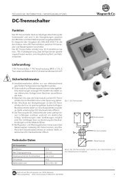
<strong>NR24</strong>/<strong>230</strong>MischerantriebServomoteur de vanneServocomando per valvoleValve actuatorA B C DE F GMontageanleitungInstruction de montageIstruzione di montaggioMounting instructionDeutschFrançaisItalianoEnglishInformationenInformationsInformazioneInformation1. Die Achse de Mischers A im Gegenuhr-zeigersinn indie Endstellung drehen (OFFEN oder ZU).2. Verdrehsicherung B in ein geeignetes Gewindelochdes Mischers schrauben (falls notwendig vorhandeneSchraube entfernen), damit der Verdrehbolzen ineinen der Schlitze am Antriebboden passt.3. Adapter C auf die Mischerachse stecken.4. Mischerantrieb D auf den Adapter C stecken(Ausliefe-rungzustand des Antriebs - im Gegenuhrzeigersinnam Anschlag), wenn nötig leicht imUhrzeigersinn drehen bis der Verdrehbolzen B ineinen der Schlitze am Antrieb geschoben werdenkann5. Das Stellungsanzeige-Schild E so drehen damit dieAnzeigeskala mit der gewünschten Funktion (OFFEN/ ZU) übereinstimmt und dann auf den Mischerantriebstecken.6. Handverstellgriff F mit Pfeilmarke auf das linkeSkalenende zeigend auf die Antriebsachse steckenund die ganze Einheit mit Schraube G festziehen.7. Mit Schraubendreher (Nr. 3) den Handverstellknopfam Antrieb von «A» auf «☞» stellen und mittelsHandgriff F den Mischer von einer Endstellung in dieandere drehen. Der Antrieb muss unbedingt voneinem Endanschlag zum anderen bewegt werdenkönnen (90°).8. Antrieb an der Nennspannung anschliessen.9. Handverstellknopf auf «A» stellen, der Antrieb läuft indie gewünschte Stellung.1. Tourner l'axe de la vanne mélangeuse A en sensinverse horaire dans la position finale.(OUVERTE ouFERMEE)2. Visser l’arrêt anti-rotation B dans un trou filetéconvenant de la vanne (si nécessaire enlever une visexistante).3. Enficher l’adapteur C sur l'axe de la vanne.4. Enficher le servomoteur D sur l’adaptateur C et (étatde livraison du servomoteur: en butée dans le sensinverse horaire), si nécessaire, le tourner légèrementen sens horaire jusqu'à ce qu'il puisse être engagédans une des fentes dans le boîtier du servomoteur5. Tourner le cadran E pour qu'il coïncide avec lafonction désirée (OUVERT / FERMEE) et le glissersur l'axe du servomoteur.6. Enficher la poignée F d'actionnement manuel sur leservomoteur dans la position pour que la flèchemontre la limite gauche de la graduation sur lecadran. Ensuite, fixer l'ensemble au moyen de la visG7. A l’aide d’un tourne-vis (No. 3) tourner le bouton dedébrayage sur le servomoteur de la position «A» sur«☞» et tourner la vanne manuellement à l'aide de lapoignée F d'une position finale à l'autre. Il estimportant que le servomoteur puisse être tournéd'une butée interne à l'autre (90°).8. Raccorder le servomoteur à la tension nominale.9. Remettre le bouton de débrayage sur «A» et leservomoteur tourne dans la position désirée.1. Girare l'asse della valvola miscelatrice A nel sensocontrario orario nella posizione finale (APERTA oCHIUSA).2. Avvitare l’arresto anti-rotazione B in un foro filettatoadeguato alla valvola (se necessario togliere unavite esistente).3. Inserire l’adattore C sull'asse della valvola.4. Inserire il servocomando D sull’adattore C e, senecessario, girarlo leggermente in senso orariofinché possa inserire in una fessure dell’involucro delservocomando (il servocomando é consegnato:chiuso nel senso inverso orario).5. Girare il quadrante E per farlo coincidere con lafunzione desiderata (APERTA/ CHIUSA)e infilarlosull'asse del servocomando.6. Inserire la manovella F di messa in moto manualesul servocomando nella posizione adeguata finché lafreccia indichi il limite sinistra della graduazione sulquadrante. Poi, fissare l’insieme con la vite G.7. Con un cacciavite (No. 3), girare il pulsante didisinnesto sul servocomando dalla posizione «A»sulla «☞» e girare la valvola manualmente con lamanovella F da una posizione finale all'altra. Èimportante che il servocomando possa esseregirato da un limite di rotazione all'altro (90°).8. Allacciare il servocomando alla tensione nominale.9. Rimettere il pulsante di disinnesto sulla «A» e ilservocomando gira nel senso desiderato.1. Turn the spindle of the valve A counter clockwise tothe end position (OPEN or CLOSED). Remove thehandle supplied with the valve body from the valvespindle.2. Screw the anti-rotation stop B in a convenient holeon the valve (if necessary remove an existingscrew).3. Slide the linkage C over the valve spindle.4. Place the actuator D onto the linkage C and ifnecessary rotate it slightly clockwise until the antirotationstop B engages in the slot of the actuator(the actuator is supplied in the anti-clockwiseposition).5. Turn the scale E into the position relevant to therequested function (OPEN/ CLOSED) and place itonto the actuator.6. Place the handle F onto the actuator ensuring thatthe arrow points to the left end position of the scale.Tighten the whole unit by means of the screw G.7. Using a screwdriver (No. 3) turn the disengagingbutton on the housing cover from «A» to «☞»position and rotate the valve by means of thehandle F from one end position to the other. It isimportant that the actuator can be moved fromone end stop to the other (90°).8. Connect the actuator to the power supply.9. Turn the disengaging button back to the«A»position and the actuator will turn in the requiredposition.Art. No. 503638.14a / 70801-0000220.03.2006
DeutschFrançaisItalianoEnglishAnwendungDer Mischerantrieb <strong>NR24</strong>/<strong>230</strong> wird für die Motorisierung vonMischhahnen eingesetzt. Die Ansteuerung erfolgt je nach Modell durchhandelsübliche Regelsysteme mit 3-Punkt Ausgang.WirkungsweiseMischerantrieb <strong>NR24</strong>/<strong>230</strong>Der Mischerantrieb wird mit Hilfe einer einzigen Schraube auf demMischhahn befestigt. Der mitgelieferte Stehbolzen dient als Verdrehsicherung.Die Montagelage kann in 90°-Schritten beliebig gewähltwerden. Durch seine kompakte und kleine Bauform passt der <strong>NR24</strong>/<strong>230</strong>in die meisten Ausschnitte der Armaturen-Isolationen.Der Drehwinkel ist auf 90° begrenzt. Bei Erreichen der Endanschläge wirdder Antrieb elektrisch abgeschaltet und ist somit stromlos.Bei allfälligen Störungen des Regelsystems kann der Antrieb mittelsDrehknopf am Gehäuse auf Handbetrieb gestellt werden. Dadurch wirddas Getriebe ausgerastet und der Mischerhahn kann durch Drehen desHandgriffs am Mischerantrieb in jede beliebige Stellung gebracht werden.Die Stellung wird an einer umkehrbaren Skala angezeigt.ApplicationServomoteur de vanne <strong>NR24</strong>/<strong>230</strong>Le servomoteur de vanne NR 24/<strong>230</strong> est utilisé pour la motorisation devannes mélangeuses. La commande se fait par des systèmes de régulation3-points usuels.Mode de fonctionnementLe servomoteur de vanne est monté sur la vanne mélangeuse à l'aide d'uneseule vis de fixation. La tige de guidage fournie avec l'appareil sert d'arrêtanti-rotation. La position de montage peut être choisie par pas de 90°. Parsa forme compacte et sa petite taille, le <strong>NR24</strong>/<strong>230</strong> peut être encastré dansla plupart des ouvertures des coffrets d'isolation prévues à cet effet.L'angle de rotation est limité à 90°. Lorsqu'il touche les butées finales, il estélectriquement coupé, c.à.d. il ne consomme plus de courant.Lors de dérangements éventuels du système de régulation, le servomoteurpeut être mis en fonctionnement manuel au moyen d'un bouton sur leboîtier. En tournant ce bouton, le réducteur est débrayé et la vannemélangeuse peut ainsi être mise dans n'importe quelle position en tournantla poignée du servomoteur. La position de la vanne mélangeuse estindiquée sur le cadran reversible.Servocomando per valvole <strong>NR24</strong>/<strong>230</strong>ApplicazioneIl servocomando <strong>NR24</strong>/<strong>230</strong> viene usato per la motorizzazione di valvolemiscelatrici. Il comando avviene tramite usuale sistema di regolazione a3 punti.FunzionamentoIl servocomando viene montato sulla valvola miscelatrice tramite una solavite. L’asta consegnata serve d’arresto anti-rotazione. La posizione demontaggio può essere scelta in passi di 90°. Grazie alla sua formacompatta e alla sua piccolezza, il <strong>NR24</strong>/<strong>230</strong> può essere inserito nellamaggior parte degli involucri d’isolazione.L'angolo di rotazione è limitato a 90°. Al raggiungimento dei limiti difunzionamento avviene un disinserimento elletrico, il motorino rimanepertanto senza tensione.In caso di guasti del sistema di regolazione il servocomando può venirportato nella posizione manuale tramite commutatore sull'involucro. Inquesta posizione può venir sganciato il meccanismo tramite un pulsante egirando la manovella, il servocomando può venir portato in qualsiasiposizione. La posizione è rilevabile su una scala riversibile.ApplicationThe valve actuator <strong>NR24</strong>/<strong>230</strong> can be used for motorising slipper valves.These acuators can be operated by any controller/compensator with a3-point output.OperationValve actuator <strong>NR24</strong>/<strong>230</strong>The actuator is mounted directly to the slipper valve spindle and fixed withone screw. An anti-rotation bolt is supplied with the actuator. Themounting position of the actuator can be chosen in steps of 90°. Thanksto its small size and compact form the <strong>NR24</strong>/<strong>230</strong> fits most of the cut-outsof the isolation boxes.The angle of rotation is limited to 90°. When the actuator reaches eitherend position the voltage supply is interrupted by limit switches.In case of a failure by the controller the actuator can be put into a manualmode by turning the button on the housing cover which will disengage thegears. The actuator can now be put in any position by turning the handleand this position is indicated by means of a reversible scale.Anschluss-SchemaSchéma de raccordementSchema di allacciamentoWiring diagramDreipunktsteuerungCommande 3 pointsControllo a tre punti3-point control~24V~/<strong>230</strong>V~L1 N L11 2 3ReglerSicherheitshinweisDer elektrische Anschlusshat gemäss den gesetzlichenVorschriften zu erfolgen.~24V~/<strong>230</strong>V~RégulateurL1 N L11 2 3Consigne de sécuritéLe branchement électriquedoit être conforme aux prescriptionslégales.~24V~/<strong>230</strong>V~RegolatoreL1 N L11 2 3ImportanteI collegamenti elettrici devonoessere conformi alle normativevigenti.~24V~/<strong>230</strong>V~ControllerL1 N L11 2 3DangerThe equipment must be connectedto the electric powersupply in a manner whichcomplies with the legalrequirements applicable at theplace of use.NR 24/<strong>230</strong>NR 24/<strong>230</strong>NR 24/<strong>230</strong>NR 24/<strong>230</strong>Technische Daten <strong>NR24</strong>/<strong>230</strong>Caractéristiques <strong>NR24</strong>/<strong>230</strong>Dati tecnici <strong>NR24</strong>/<strong>230</strong>Technical data <strong>NR24</strong>/<strong>230</strong>SpeisespannungLeistungsverbrauchDimensionnierungSchutzklasseAnschlussDrehwinkelDrehmomentLaufzeitDrehsinnHandverstellungStellungsanzeigeUmgebungstemperaturWartungGewicht24 V ~/ <strong>230</strong> V~ 50 Hz2,5 W (5 Nm) 3,5 W (10 Nm)2,5 VA (5Nm), 3,5 VA (10Nm)II (schutzisoliert)Klemmen90° elektrisch begrenzt5 Nm oder 10 Nm70 s, 140 s oder 280 swählbar an Klemmenmech. Getriebeausrastungumkehrbares Anzeigeschild0°C...+50°Cwartungsfrei400 gTension d'alimentationConsommationDimensionnementClasse de protectionRaccordementAngle de rotationCouple de rotationTemps de marcheSens de rotationPositionnement manuelIndication de positionTempérature ambianteEntretienPoids24 V~/ <strong>230</strong> V~ 50 Hz2,5 W (5 Nm) 3,5 W (10 Nm)2,5 VA (5Nm), 3,5 VA (10Nm)II (isolation de sécurité)bornier90° limité électriquement5 Nm ou 10 Nm70 s, 140 s ou 280 ssélectable aux bornesdébrayage mécaniquecadran reversible0°C...+50°Csans entretien400 gTensione di alimentazione 24 V~/ <strong>230</strong> V~ 50 HzPotenza assorbita 2,5 W (5 Nm) 3,5 W (10 Nm)Dimensionamente 2,5 VA (5Nm), 3,5 VA (10Nm)Classe di protezione II (isolamento di protezione)AllacciamentomorsettieraAngolo di rotazione 90° limitato elettr.Momento torcente 5 Nm o 10 NmTempo di rotazione 70 s, 140 s o 280 sSenso di rotazione selezionabile alla morsettieraAzionamento manuale disinnestamento meccanicoIndicazione della posizione su scala riversibileTemperatura ambiente 0°C...+50°CManutenzionenessunaPeso400 gPower supply24 V ~/ <strong>230</strong> V~ 50 HzPower consumption 2,5 W (5 Nm) 3,5 W (10 Nm)For wiring sizing 2,5 VA (5Nm), 3,5 VA (10Nm)Protection class II (without earth wire)ConnectionterminalsAngle of rotation electrically limited to 90°Torque5 Nm or 10 NmRunning time70 s, 140 s or 280 sDirection of rotation selectable on terminalsManual operation mechanical disengagementIndication of position reversible scaleAmbient temperature 0°C...+50°CMaintenancemaintenance-freeWeight400 gMONTAGEBEISPIEL AUF DER RÜCKSEITEEXEMPLE DE MONTAGE AU VERSOESEMPIO DI MONTAGGIO SUL RETROFITTING INSTRUCTIONS SEE OVERLEAFArt. No. 503638.14a