MODEL 2604 CONTROLLER - USER GUIDE - d a n m a r k
MODEL 2604 CONTROLLER - USER GUIDE - d a n m a r k
MODEL 2604 CONTROLLER - USER GUIDE - d a n m a r k

You also want an ePaper? Increase the reach of your titles
YUMPU automatically turns print PDFs into web optimized ePapers that Google loves.
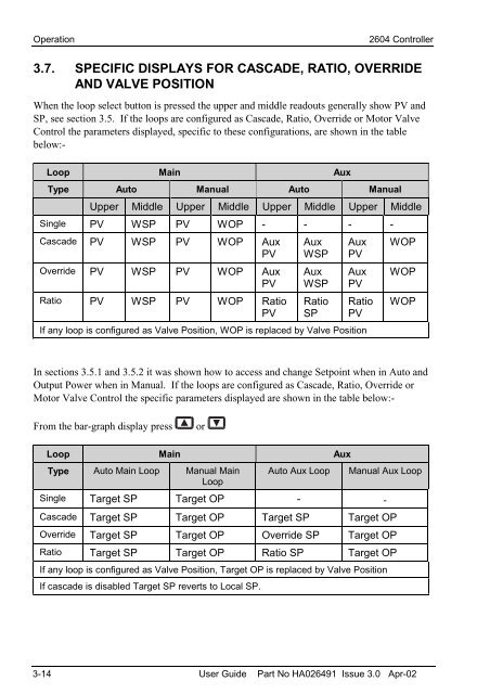
Operation <strong>2604</strong> Controller3.7. SPECIFIC DISPLAYS FOR CASCADE, RATIO, OVERRIDEAND VALVE POSITIONWhen the loop select button is pressed the upper and middle readouts generally show PV andSP, see section 3.5. If the loops are configured as Cascade, Ratio, Override or Motor ValveControl the parameters displayed, specific to these configurations, are shown in the tablebelow:-Loop Main AuxType Auto Manual Auto ManualUpper Middle Upper Middle Upper Middle Upper MiddleSingle PV WSP PV WOP - - - -Cascade PV WSP PV WOP AuxPVOverride PV WSP PV WOP AuxPVRatio PV WSP PV WOP RatioPVAuxWSPAuxWSPRatioSPAuxPVAuxPVRatioPVIf any loop is configured as Valve Position, WOP is replaced by Valve PositionWOPWOPWOPIn sections 3.5.1 and 3.5.2 it was shown how to access and change Setpoint when in Auto andOutput Power when in Manual. If the loops are configured as Cascade, Ratio, Override orMotor Valve Control the specific parameters displayed are shown in the table below:-From the bar-graph display pressorLoop Main AuxType Auto Main Loop Manual Main Auto Aux Loop Manual Aux LoopLoopSingle Target SP Target OP - -Cascade Target SP Target OP Target SP Target OPOverride Target SP Target OP Override SP Target OPRatio Target SP Target OP Ratio SP Target OPIf any loop is configured as Valve Position, Target OP is replaced by Valve PositionIf cascade is disabled Target SP reverts to Local SP.3-14 User Guide Part No HA026491 Issue 3.0 Apr-02