MODEL 2604 CONTROLLER - USER GUIDE - d a n m a r k
MODEL 2604 CONTROLLER - USER GUIDE - d a n m a r k
MODEL 2604 CONTROLLER - USER GUIDE - d a n m a r k

Create successful ePaper yourself
Turn your PDF publications into a flip-book with our unique Google optimized e-Paper software.
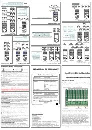
<strong>2604</strong> Controller InstallationTransducerPowerSupplyProvide 5Vor 10Vdc topower StrainGaugeTransducer+ShuntContactG3orG5ToFixedorModulePVInputBCExternal calibrationresistor (may be fittedin transducer).A+_ABCDDNote: To minimise noise pick up it isrecommended that screened cables are used forstrain gauge power supply connections.PotentiometerInput(100Ω to15KΩ)MotorisedvalvepositionfeedbackRemote SPVU+0.5vWiper0vABCDDual PVInput(Modules 3& 6 only)To accepttwo inputsfrom a highlevel and alow levelsource.The twoinputs arenot isolatedfrom eachother.DPCurrentsource+-+-Currentsource2.49Ω0-2Vinput100Ω0-20mAinputThe common connections to terminal D must bereturned separately to D as shown in the dualcurrent example above.ABCDFigure 2-18: Wiring Connections for IO ModulesUser Guide Part No HA026491 Issue 3.0 Apr-02 2-23