MODEL 2604 CONTROLLER - USER GUIDE - d a n m a r k
MODEL 2604 CONTROLLER - USER GUIDE - d a n m a r k
MODEL 2604 CONTROLLER - USER GUIDE - d a n m a r k

Create successful ePaper yourself
Turn your PDF publications into a flip-book with our unique Google optimized e-Paper software.
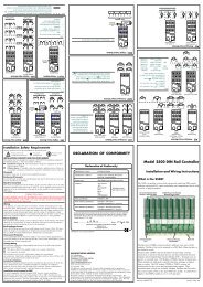
Installation<strong>2604</strong> Controller2.4. OPTIONAL PLUG IN MODULE CONNECTIONS2.4.1. Digital Communications ConnectionsDigital Communications modules can be fitted in two positions in the <strong>2604</strong> controller. Theconnections are available on HA to HF or JA to JF depending on the position in which themodule is fitted. The two positions could be used, for example, to communicate with aconfiguration package, such as ‘iTools’ on one position and to a PC running a supervisorypackage on the second position OR with master/slave communications.The connections shown in the following diagrams show RS232, 2-wire RS485, 4-wire RS422and master/slave comms to a second controller.Do not run digital communications wiring with power cables. The following diagrams showconnections for ‘bench top test’ wiring. For a full description of the installation of acommunications link, including line resistors, see Communications Handbook, Part No.HA026230, and EMC Installation Guide, part no. HA025464.RS232PCHAHBRxTxComHCHDCommonHERxHFTxFigure 2-11: RS232 Communications ConnectionsRS485 - 2 wirePCConnections ‘daisychained’ to otherinstrumentsHAHBRS232 toRS4852-wireconverterRx Tx ComRxB TxBRxA Com TxAHCHDHEHFCommonA(+)B(-)Figure 2-12: RS485 2- Wire Communications Connections2-12 User Guide Part No HA026491 Issue 3.0 Apr-02