MODEL 2604 CONTROLLER - USER GUIDE - d a n m a r k
MODEL 2604 CONTROLLER - USER GUIDE - d a n m a r k
MODEL 2604 CONTROLLER - USER GUIDE - d a n m a r k

Create successful ePaper yourself
Turn your PDF publications into a flip-book with our unique Google optimized e-Paper software.
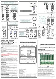
<strong>2604</strong> Controller Installation2.3.6. Digital I/OEight digital I/O connections are provided as standard. They can be individually configuredas:1. Inputs Run, Hold, Reset, Auto/Manual, etc, - logic or contact closure.2. Outputs Configurable as Control outputs, Programmer Events, Alarms, etc.Digital IO is not isolated from instrument ground.Digital Inputs (Logic Inputs or Contact Closure in any combination)CommonLogicinputs (1)ContactclosureinputsDCD1D2D3D4D5D6D7D8CommonThis terminal can beused for DigitalInput only (not DO)Note 1:Logic inputs can accept drive signals froma voltage source where:4V = Inactive (0) Limit +35VThis action is reversed if the input hasbeen configured as ‘Inverted’Digital Outputs (Relay, Thyristor or SSR Drive in any combination)External power supply 10 to 35 Vdc.Each output is current limited to 40mARelay+_RelayOutputs areopen collectorDCD1D2RelayThyristorUnitSSRThyristorUnitSSRD3D4D5D6D7Figure 2-10: Wiring Connections for Digital I/OUser Guide Part No HA026491 Issue 3.0 Apr-02 2-11