MODEL 2604 CONTROLLER - USER GUIDE - d a n m a r k
MODEL 2604 CONTROLLER - USER GUIDE - d a n m a r k
MODEL 2604 CONTROLLER - USER GUIDE - d a n m a r k

You also want an ePaper? Increase the reach of your titles
YUMPU automatically turns print PDFs into web optimized ePapers that Google loves.
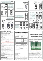
<strong>2604</strong> Controller Installation2.3.4. Analogue Input ConnectionsThe analogue input is supplied as standard and is intended to accept 0 to 10 Vdc from avoltage source. A milli-amp current source can be used by connecting a 100Ω resistor acrossterminals BA and BB. This input can be used as a remote setpoint input, remote setpoint trimor as a high level PV input to a control loop. This input is not isolated from the digital IO.Non-isolated Voltage Source (0 to 10V)BABBBC+-If screened cable isused earth at the supplyendNonisolated0 to10VdcsourceNon-isolated Current Source (0 - 20mA) (4 - 20mA)BABBBC+-100ΩIf screened cable isused earth at the supplyendNonisolatedcurrentsourceIsolated Voltage Source (0 to 10V)BABBBC+-ScreenIsolated0 to10VdcsourceIsolated Current Source (0 - 20mA) (4 - 20mA)BABBBC+-100ΩScreenIsolatedcurrentsourceFigure 2-7: Wiring Connections For Analogue InputUser Guide Part No HA026491 Issue 3.0 Apr-02 2-9