MODEL 2604 CONTROLLER - USER GUIDE - d a n m a r k
MODEL 2604 CONTROLLER - USER GUIDE - d a n m a r k
MODEL 2604 CONTROLLER - USER GUIDE - d a n m a r k

Create successful ePaper yourself
Turn your PDF publications into a flip-book with our unique Google optimized e-Paper software.
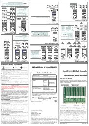
Installation<strong>2604</strong> Controller2.3.3. Sensor Input ConnectionsThe fixed PV input can accept a range of sensors including Thermocouple, RTD (Pt100),Pyrometer, Voltage (e.g. 0-10Vdc) or Milliamp (e.g. 4-20mA) signals. These sensors are usedto provide inputs to Control Loop 1.Thermocouple or PyrometerUse the correct type ofcompensating cableto extend wiring+-VHVIV+V-RTD (Pt100)3-wireplatinumresistancethermometerFor 2-wirethis is alocal linkVHVIV+V-Voltage 0 to 10V or 0 to 2VCurrent 0 to 20mA (4 to 20mA)+0 - 10Voltsource-VHVIV+V-+Currentsource-2.49ΩresistorsuppliedVHVIV+V-mV (up to 80mV)+mVoltsource-VHVIV+V-Notes:1. Do not run input wires together withpower cables2. Pay attention to line resistance; a highline resistance may cause measurementerrors3. When shielded cable is used, it shouldbe grounded at one end only to avoidground loop currents4. The resistance of the 3 PRT wires mustbe the same5. For TC wiring use the appropriatecompensating cableFigure 2-6: Wiring Connections For PV Input2-8 User Guide Part No HA026491 Issue 3.0 Apr-02