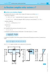
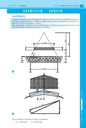
modulo D I pontiUnità 3 I ponti in muratura2Raggio di intradosso [fig. a]:ri =c + f2 ⋅ f300 , + 120 ,=2×120 ,2 2 2 2= 435 , mper cui:cα = arctg arctgr− f= 300 ,≈ 43° , 60 < 60°435 , −120,SpalleFormula di Lesguiller:lS =⎡⎛+ ⋅ + ⋅ H⎞′ l H f sch⎣⎢⎝055 , 020 , 0, 04⋅ f + s ⎠ ⋅ ⎤c⎦⎥ + [ 0,01852⋅ ( ′+ + )]⋅==⎡⎛+ × + ×⎞⎣⎢ ⎝055 , 020 , 600 ,004 , 300 , × + ⎠ × 600 ,⎤2 1, 20 0,60 ⎦⎥ ++ [ 0, 0185 × ( 3, 00 + 1, 20 + 0, 60)]× 0, 75 ≈2, 70 mFormula di Leveillé:S= (, 0 33+ 0, 212 ⋅l)⋅H′⋅l=( f + s ) ⋅ ( H′+ s + h)cc= (, 0 33+ 0, 212 × 6, 00)×300 , × 600 ,( 1, 20 + 0, 60) × ( 3, 00 + 0, 60 + 0, 75)≈ 243m ,Formula del Genio Civile Italiano:lS= 0, 05 ⋅ H′ + 0, 20 ⋅ l+ ⋅ ( 0, 10 + 0,005 ⋅l)=f= 005× 300+ 020× 600+ 600 ,, , , , × ( 0, 10 + 0, 005 × 6, 00)≈2, 00 m120 ,In base ai valori ottenuti viene fissato un valore della spalla S = 2,40 m.Essendo il ponte simmetrico e simmetricamente caricato, viene considerata solo metà volta compresafra le sezioni in chiave e all’imposta per la larghezza di 1,00 m.aU. Alasia - M. Pugno, Corso di Costruzioni 5 © SEI, 2011
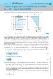
modulo D I pontiUnità 3 I ponti in muratura3Dopo aver tracciato la metà volta con i relativi strati sovrastanti, la volta stessa viene suddivisa inconci ideali, in questo caso sei [fig. b], e dai punti di estradosso dei giunti si innalzano le verticaliche delimitano i volumi dei vari strati, i quali sono costituiti di materiali diversi con pesi volumicidifferenti, e analogamente si ha per il carico variabile dovuto al traffico.Per una semplificazione dei calcoli, le varie altezze reali h r degli strati in corrispondenza dei giuntivengono trasformate in altezze ideali h i riferite al peso volumico γ c del materiale costituente lavolta, per cui gli strati reali, compreso il carico variabile, vengono trasformati in altri ideali equipesanti,immaginando di realizzarli con lo stesso materiale della volta.Indicando genericamente con γ il peso volumico del materiale di uno strato e con q il carico variabile,deve quindi sussistere l’uguaglianza:h i ⋅ γ c = h r ⋅ γda cui:γh i = h r ⋅ =h r ⋅ cγ cbAnalisi dei carichiPermanente strutturale [figg. a e b]Ogni concio ideale viene assimilato a un prisma con altezza di 1,00 m a basi trapezoidali di altezzauguale allo spessore s c della volta e basi curve assimilabili a trapezi di lunghezza uguale a 1/6degli sviluppi di intradosso Sv i e di estradosso Sv e che risultano:π ⋅ rSv i =i ⋅ α π ⋅ 4,35 × 43°,60= ≈3,31 m180° 180°π ⋅ (rSv e =i + s c ) ⋅ α π ⋅ (4,35 + 60) × 43°,60= ≈3,77 m180°180°Il peso di ogni concio, applicando il coefficiente parziale di sicurezza γ G1 = 1,35, risulta:3,31 + 3,77G c = ⎛ 1× ×0,60 × 1,00⎞m 3 × 24 kN/m 3 × 1,35 ≈ 11,48 kN⎝ 6 2⎠e il vettore che lo rappresenta viene applicato nel baricentro di ogni concio [fig. c].Permanente non strutturaleIn tabella 1 sono riportate le diverse altezze reali h r , misurate sul grafico [fig. b], e le relative altezzeideali h i .Le diverse strisce sono prismi con altezza orizzontale di 1,00 m e basi assimilabili a trapezi conbasi corrispondenti alle altezze ideali h i,p .U. Alasia - M. Pugno, Corso di Costruzioni 5 © SEI, 2011