Automatic Antenna Tuner FC-30 Installation Instructions - Yaesu
Automatic Antenna Tuner FC-30 Installation Instructions - Yaesu
Automatic Antenna Tuner FC-30 Installation Instructions - Yaesu
- No tags were found...

You also want an ePaper? Increase the reach of your titles
YUMPU automatically turns print PDFs into web optimized ePapers that Google loves.
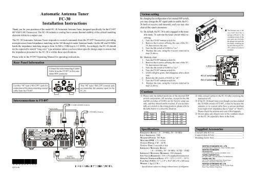
<strong>Automatic</strong> <strong>Antenna</strong> <strong>Tuner</strong><strong>FC</strong>-<strong>30</strong><strong>Installation</strong> <strong>Instructions</strong>Thank you for your purchase of the model <strong>FC</strong>-<strong>30</strong> <strong>Automatic</strong> <strong>Antenna</strong> <strong>Tuner</strong>, designed specifically for the FT-897HF/VHF/UHF Transceiver. The <strong>FC</strong>-<strong>30</strong> includes a cooling fan to ensure thermal stability of the critical matchingelements within its compact case.The <strong>FC</strong>-<strong>30</strong> <strong>Automatic</strong> <strong>Antenna</strong> <strong>Tuner</strong> responds to control commands from the FT-897 Transceiver, providingmicroprocessor-based impedance matching on the 160 through 6 meter Amateur bands. On the HF and 50 MHzbands the impedance matching range is from 16.5Ω to 150Ω (up to 3:1 SWR). Accordingly, the <strong>FC</strong>-<strong>30</strong> shouldnot be expected to match “long wire” type antennas unless you have taken specific design steps to ensure thatthe impedance presented to the <strong>FC</strong>-<strong>30</strong> is within these specifications.Various settingBy changing the configuration of an internal DIP switch,you may change the RF signal path (to enable the <strong>FC</strong>-<strong>30</strong> both on receive and transmit), and you may alsoclear all the tuner's memories.A) By default, the <strong>FC</strong>-<strong>30</strong> is only engaged in the transmitmode. To activate the tuner circuit while receiving.1. Turn the FT-897 POWER switch OFF.2. Remove the 6 screws affixing the case of the <strong>FC</strong>-<strong>30</strong>, then remove the case.3. Turn the 8th switch of S1003 to "on."4. Replace the case, using the 6 screws removed instep (2) above.The bottom case is thecase half that has asponge affixed to theventilation screen. If thecase parts are reversed,the sponge can touch thefan blades, disabling thefan and allowing the <strong>FC</strong>-<strong>30</strong>'s control circuitry tooverheat.Please refer to the FT-897 Operating Manual for operating instructions.Rear Panel InformationUse this “M” type (“SO-239”) jack forconnection of the interconnecting coaxialcable from the FT-897.Connect the interconnecting ControlCable from the FT-897 to this miniatureDIN connector.This “M” type (“SO-239”) coaxial jackaccommodate the antenna input for the<strong>FC</strong>-<strong>30</strong>.B) Memory clear1. Turn the FT-897 POWER switch OFF.2. Remove the 6 screws affixing the case of the <strong>FC</strong>-<strong>30</strong>, then remove the case.3. Turn the 4th switch of S1003 to "on."4. Turn the FT-897 POWER switch ON.5. LED0 will glow green, then disappear, after a shorttime.6. Return the 4th switch of S1003 to "off ."7. Turn the FT-897 POWER switch OFF.8. Replace the case, using the 6 screws removed instep (2) above.CautionsLED04th of switch8th of switchInterconnections to FT-897CAT/LINEARControl Cable144MHz/4<strong>30</strong>MHzTo 144MHz/ 4<strong>30</strong>MHz <strong>Antenna</strong>CTRLANTTo HF/50MHz <strong>Antenna</strong>❍ Please note the default positions of the internal DIPswitch components. All switches, except for the 4thand 8th switches of S1003, are for factory setup useonly, and they should not be touched. If you accidentallyset a switch to the wrong position, please refer tothe table below to correct the situation.S1002No. Switch1 OFF2 OFFS1003No. Switch No. Switch1 OFF 5 ON2 OFF 6 ON3 OFF 7 OFF4 OFF 8 OFF❍ Only connect cables to the <strong>FC</strong>-<strong>30</strong> after switching thetransceiver off.❍ If the <strong>FC</strong>-<strong>30</strong> doesn't tune even though you have pushedthe TUNER switch of FT-897, it may be because theantenna or its coaxial cable have a serious problem(very high or low impedance due to "open" or "short").Please check the antenna and coax if this happens.❍ Do not place any objects next to the ventilator ductson the <strong>FC</strong>-<strong>30</strong>, especially those in the front.E A C 8 6 X 7 0 00205A-0KINPUT22AGNDDATAHF/50MHzACCKEYANTSuppliedCoaxial CableTRXSpecificationsFREQUENCY RANGE: 1.8 ~ <strong>30</strong> MHz, 50 ~ 54 MHzINPUT IMPEDANCE: 50ΩMAXIMUM POWER: 100 WattsMATCHED SWR: 1.5:1 or lessTUNE-UP POWER: 4 W ~ 60 WTUNE-UP TIME: 5 seconds or lessIMPEDANCE MATCHING RANGE:1.8 ~ <strong>30</strong> MHz, 50 ~ 54 MHz: 16.5Ω ~ 150ΩIMPEDANCE MATCHING MEMORIES: 100 channelsINPUT VOLTAGE REQUIREMENT: 13.8V ±15% (supplied from transceiver)OPERATING TEMPERATURE RANGE: 14° F ~ 122° F (−10 °C ~ +50 °C)CASE SIZE (WHD): 3.1” x 1.8” x 10.2” (80 x 45 x 260 mm)WEIGHT: 1 kg (2.2 lb.)Specifications subject to change without notice of obligation.Supplied AccessoriesCoaxial Cable (0.5 m) .................................................... 1Control Cable (0.5 m) .................................................... 1Mounting Screw Assy..................................................... 1VERTEX STANDARD CO., LTD.4-8-8 Nakameguro, Meguro-Ku, Tokyo 153-8644, JapanVERTEX STANDARDUS Headquarters10900 Walker Street, Cypress, CA 906<strong>30</strong>, U.S.A.YAESU EUROPE B.V.P.O. Box 75525, 1118 ZN Schiphol, The NetherlandsYAESU UK LTD.Unit 12, Sun Valley Business Park, Winnall CloseWinchester, Hampshire, SO23 0LB, U.K.VERTEX STANDARD HK LTD.Unit 5, 20/F., Seaview Centre, 139-141 Hoi Bun Road,Kwun Tong, Kowloon, Hong Kong