CO N TRO LLER ATR142 Manuale Installatore User Manual
CO N TRO LLER ATR142 Manuale Installatore User Manual
CO N TRO LLER ATR142 Manuale Installatore User Manual

Create successful ePaper yourself
Turn your PDF publications into a flip-book with our unique Google optimized e-Paper software.
- REGO LATO RE- <strong>CO</strong>N <strong>TRO</strong> <strong>LLER</strong><strong>ATR142</strong>M a nua le I nsta lla tore<strong>User</strong> Ma nua l
Summary1 Introduction...........................................................................................42 Model Identification...............................................................................43 Technical Data .....................................................................................53.1 General Features........................................................................................ 53.2 Hardware Features..................................................................................... 53.3 Software Features ...................................................................................... 64 Dimensions and Installation..................................................................65 Electrical wirings...................................................................................75.1 Wiring diagram ........................................................................................... 76 Display and Key Functions .................................................................106.1 Numeric Indicators (Display) .................................................................... 116.2 Meaning of Status Lights (Led) ................................................................ 116.3 Keys.......................................................................................................... 117 Controller Functions ...........................................................................127.1 Modifying Main Setpoint and Alarm Setpoint Values ............................... 127.2 Auto-Tune................................................................................................. 127.3 <strong>Manual</strong> Tuning.......................................................................................... 127.4 Automatic Tuning...................................................................................... 137.5 Soft Start................................................................................................... 137.6 Automatic/<strong>Manual</strong> Regulation for % Output Control ................................ 137.7 Pre-Programmed Cycle............................................................................ 147.8 Memory Card (optional)............................................................................ 157.9 Loading default values.............................................................................. 167.10 LATCH ON Functions............................................................................... 167.11 Digital Input Functions.............................................................................. 187.12 Dual Action Heating-Cooling .................................................................... 198 Serial Communication ........................................................................218.1 Slave......................................................................................................... 218.2 Master....................................................................................................... 269 Configuration......................................................................................289.1 Modify Configuration Parameter............................................................... 2810 Table of Configuration Parameters .....................................................2911 Alarm Intervention Modes...................................................................4312 Table of Anomaly Signals...................................................................4813 Summary of Configuration parameters ...............................................492
Sommario14 Introduzione........................................................................................5215 Identificazione del modello .................................................................5216 Dati tecnici..........................................................................................5316.1 Caratteristiche generali............................................................................. 5316.2 Caratteristiche hardware .......................................................................... 5316.3 Caratteristiche software............................................................................ 5417 Dimensioni e installazione ..................................................................5418 Collegamenti elettrici ..........................................................................5518.1 Schema di collegamento .......................................................................... 5519 Funzione dei visualizzatori e tasti .......................................................5819.1 Indicatori numerici (display)...................................................................... 5919.2 Significato delle spie di stato (led)............................................................ 5919.3 Tasti.......................................................................................................... 5920 Funzioni del regolatore .......................................................................6020.1 Modifica valore setpoint principale e setpoint di allarme.......................... 6020.2 Auto-tune .................................................................................................. 6020.3 Lancio del Tuning <strong><strong>Manual</strong>e</strong> ...................................................................... 6020.4 Tuning Automatico.................................................................................... 6120.5 Soft Start................................................................................................... 6120.6 Regolazione automatico / manuale per controllo % uscita ...................... 6120.7 Ciclo pre-programmato............................................................................. 6220.8 Memory Card (opzionale)......................................................................... 6320.9 Caricamento valori di default.................................................................... 6420.10 Funzione LATCH ON................................................................................ 6420.11 Funzioni da Ingresso digitale.................................................................... 6620.12 Funzionamento in doppia azione (caldo-freddo)...................................... 6721 Comunicazione Seriale.......................................................................6921.1 Slave......................................................................................................... 6921.2 Master....................................................................................................... 7422 Configurazione ...................................................................................7622.1 Modifica parametro di configurazione ...................................................... 7623 Tabella parametri di configurazione....................................................7724 Modi d’intervento allarme....................................................................9125 Tabella segnalazioni anomalie............................................................9626 Promemoria configurazione................................................................973
1 IntroductionThank you for choosing a Pixsys controller.With the <strong>ATR142</strong> model Pixsys makes available in a single device allthe resources relevant to sensor input and actuators command, inaddition to the extended power range 24…230 Vac/Vdc. With 17sensors to select and outputs configurable as relay or SSR command,the user or retailer can reduce warehouse stock by rationalisinginvestment and device availability. The series is completed withmodels equipped with serial communication RS485 Modbus. Theconfiguration is further simplified by the Memory cards which areequipped with internal battery and therefore don’t require cabling topower the controller.2 Model IdentificationThe range of <strong>ATR142</strong> controllers comes in two versions. Refer to thetable below to easily select your preferred model.Models available, with power 24…230 Vac/Vdc+/-15% 50/60Hz – 4,6VA<strong>ATR142</strong>-ABC<strong>ATR142</strong>-ABC-T2 relays (8A+5A) + 1 SSR1 relays 8A + 1 Ssr + RS4854
3 Technical Data3.1 General FeaturesDisplays 4 0.40 inch displays +4 0.30 displaysOperating 0-45°C, humidity 35..95uR%temperatureSealing IP65 front panel (with gasket)IP30 casing and IP20 terminalsMaterial Polycarbonate UL94V0 self-extinguishingWeight 100 g3.2 Hardware FeaturesAnalogue AN1input Configurable via softwareInputThermocouple type K, S, R, JAutomatic compensation of coldjunction from 0°C to 50°C.Thermoresistance: PT100,PT500, PT1000, Ni100, PTC1K,NTC10K (β 3435K)Linear: 0-10V, 0-20 or4-20mA, 0-40mVRelayoutputPotentiometers: 6KΩ, 150KΩ,2 relays (<strong>ATR142</strong>-ABC)1 relay (<strong>ATR142</strong>-ABC-T)Configurable as command and/oralarm outputSSR output 1 SSRConfigurable as command outputand/or alarm output.Supply Power supply24..230 Vac/Vdc +/-15% 50/60HzTolerance (25°C)+/-0.2 % ± 1 digitfor thermocoupleinput, thermoresistance andV/mA.Cold junctionaccuracy 0.1°C/°CContacts:Q1: 8A-250V~ forresistive loadsQ2: 5A-250V~ forresistive loads12Vdc/30mAPower consumption4.6VA5
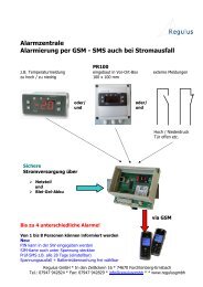
3.3 Software FeaturesRegulation algorithms ON-OFF with hysteresis.P, PI, PID, PD with proportional timeProportional band 0...9999°C or °FIntegral time 0,0...999,9 sec (0 excluded)Derivative time 0,0...999,9 sec (0 excluded)Controller functions <strong>Manual</strong> or automatic Tuning, configurablealarms, protection of command and alarmsetpoints, activation of functions via digitalinput, preset cycle with Start/Stop.4 Dimensions and InstallationDima di foratura28.5 x 70.5 mmFrontal panel cut-outSpessore suggerito2 ÷8 mmSuggested thicknessGuarnizione per 32x74Cod. 1620.00.082 (optional)Gasket for 32x74Memory Card (optional)Cod. MEMORY C24142mminserimentoMemory CardMEMORY C.12142mminsertMemory CardMemory Card (optional)with batteryCod. MEMORY C243U1C11 1 NC 635 mm1 2 3677 mm753 mm
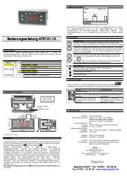
5 Electrical wiringsAlthough this controller was designed to resist noises inindustrial environments, pease notice following safetyguidelines:• Separate the feeder line from the power lines.• Avoid placing near units with remote control switches,electromagnetic contactors, high powered motors and in all instancesuse specific filters.• Avoid placing near power units, particularly if phase controlled.5.1 Wiring diagramThe connections are reported below for the three models available.PIXSYS<strong>ATR142</strong>-ABC8A 230VResistive1/2HPQ15A 230VResistive1/8HPQ22 wire 4/20mAPowerPT/NI100/1KPTC/NTC1 2 3 4 5 6 7 8 9 10 11 121MemoryPIXSYS<strong>ATR142</strong>-ABC-T8A 230VResistive1/2HPQ1RS4852 wire 4/20mAPowerPT/NI100/1KPTC/NTC1 2 3 4 5 6 7 8 9 10 11 121Memory7
Power1 224...230VAC/DCSwitching power supply with extended range24…230 Vac/dc ±15% 50/60Hz – 5,5VA.AN1 Analogue Input11 12-Tc+Shield/SchermoFor thermocouples K, S, R, J.• Comply with polarity• For possible extensions, use acompensated wire and terminals suitablefor the thermocouples used (compensated)• When shielded cable is used, it should begrounded at one side only10 11 1210 11ABCShield/SchermoPT/NI100Shield/SchermoPTC/NTCFor thermoresistances PT100, NI100• For the three-wire connection use wireswith the same section• For the two-wire connection short-circuitterminals 10 and 12• When shielded cable is used, it should begrounded at one side only to avoid groundloop currentsRED 10WHITE 11RED 12For thermoresistances NTC, PTC, PT500,PT1000 e potentiometers• When shielded cable is used, it shouldbe grounded at one side only to avoidground loop currents9 10 11 12Shield/Schermo+VDC-V/I+For linear signals V/mA• Comply with polarity• When shielded cable is used, it should begrounded at one side only to avoid groundloop currents8
Examples of Connection for linear input12110...10VFor signals 0….10V Comply with polarity12 11 90/4...20mAPRESSURE TRANSMITTERFor signals 0/4….20mAwith three-wire sensor Comply with polarityC=Sensor outputB=Sensor groundA=Sensor power12110/4...20mAFor signals 0/4..20mAwith external power of sensorExternal supplyPRESSURE TRANSMITTER12 94...20mAPRESSURE TRANSMITTER Comply with polarityC=Sensor outputB=Sensor groundFor signals 0/4...20mAwith two-wire sensor Comply with polarityC=Sensor outputA=Sensor power supplySerial input6 7 11-+RS485Shield/SchermoRS485 Modbus RTU communicationDo not use LT (line termination) resistors For networks with more than fiveinstruments supply in low voltage9
Relay Q1 OutputQ2Q17 6 5 4 3Capacity:Q1• n.o. contact : 8A/250V~ - ½HP• n.c. contact : 8A/250V~ for resistive loadsQ2• 5A/250V~ for resistive loadsSSR outputSSR8SSR command output 12V/30mA9Digital Input on ATR243-20ABC10 11Digital input using parameter .The use of digital input in this version is possibleonly with TC sensors, 0…10V, 0/4…20mA and0…40mV6 Display and Key Functions1912101 2 3M T R113 4 5 6 7 8 210
6.1 Numeric Indicators (Display)Normally displays the process. During the1configuration phase, it displays the parameterbeing inserted.Normally displays the setpoint. During the2configuration phase, it displays the parametervalue being inserted.6.2 Meaning of Status Lights (Led)3 ON when the output command is on. For motorised valvecommand, led in on when valve is opening and blinkwhen closing.4 ON when alarm 1 is on.5 ON when alarm 2 is on.6 ON when the “<strong>Manual</strong>” function is on.7 ON when the controller is running an “Autotune” cycle.8 ON when the controller communicates via serial port.6.3 Keys9 • Allows to increase the main setpoint.• During the configuration phase, allows to slide throughparameters. Together with theSETkey it modifies them.• Pressed after the key it allows to increase the alarmsetpoint.10 • Allows to decrease the main setpoint.• During the configuration phase, allows to slide through1112SETFNCSETparameters. Together with theSETkey it modifies them.• Pressed after the key it allows to decrease the alarmsetpoint.• Allows to display the alarm setpoint and runs theautotuning function.• Allows to vary the configuration parameters.SET• Allows to display the alarm setpoint and runs theautotuning function.• Allows to vary the configuration parameters.11
7 Controller Functions7.1 Modifying Main Setpoint and Alarm Setpoint ValuesThe setpoint value can be changed from the keyboard as follows:123Press Effect OperationorSEToValue on display 2changesVisualize alarmsetpoint on display1Value on display 2changesIncreases or decreases themain setpointIncreases or decreases thealarm set point value7.2 Auto-TuneThe Tuning procedure calculates the controller parameters and can bemanual or automatic according to selection on parameter 46 .7.3 <strong>Manual</strong> TuningThe manual procedure allows the user greater flexibility to decidewhen to update PID algorithm work parameters. The procedure can beactivated in two ways.• By running Tuning from keyboard:Press the12FNCkey until display 1 shows the writingwithdisplay 2 showing , press , display 2 shows .The led switches on and the procedure begins.• By running Tuning from digital input:Select on parameter 50 .On first activation of digital input (commutation on front panel) theled switches on and on second activation switches off.
7.4 Automatic TuningAutomatic tuning activates when the controller is switched on or whenthe setpoint is modified to a value over 35%.To avoid an overshoot, the treshold where the controller calculates thenew PID parameters is determined by the setpoint value minus the“Set Deviation Tune” ( see Parameter 47 ).To exit Tuning and leave the PID values unchanged, just press theFNCkey until display 1 shows the writingshowing , press , display 2 shows .The led switches off and the procedure finishes.7.5 Soft Startwith the displayTo reach the setpoint the controller can follow a gradient expressed inunits (e.g. degree/hour).Set the increase value in parameter 51 with the desiredunits/hour; only on subsequent activation the controller uses the softstart function.Automatic/manual tuning cannot be enabled if the Soft start is active.7.6 Automatic/<strong>Manual</strong> Regulation for % Output ControlThis function allows you to select automatic functioning or manualcommand of the output percentage.With parameter 49• The first selection, you can select two methods.allows you to enable theFNCkey withthe writing on display 1, while display two shows .Press the key to show ; it is now possible, during theprocess display, to change the output percentage using the keysand. To return to automatic mode, using the sameprocedure, select on display 2: the led switches offand functioning returns to automatic mode.13
• The second selection enables the same functioning, butwith two important variants:• If there is a temporary lack of voltage or after switch-off, themanual functioning will be maintained as well as the previously setoutput percentage value.• If the sensor breaks during automatic functioning, the controllermoves to manual mode while maintaining the output percentagecommand unchanged as generated by the PID immediately beforebreakage.7.7 Pre-Programmed CycleThe pre-programmed cycle function activates by settingparameter 48 .The controller reaches setpoint1 basing on the gradient set inparameter 51 , then it reaches maximum power up tosetpoint2. When the process reaches maximum power, this setpoint ismaintained for the time set in parameter 52 .On expiry, process will reach ambient temperature according togradient entered on parameter 64will be desabled and display will visualize .in, then command outputThe cycle starts at each activation of the controller, or via digital inputif it is enabled for this type of functioning (see parameter 50 ).14
7.8 Memory Card (optional)Parameters and setpoint values can be duplicated from one controllerto another using the Memory card.There are two methods:• With the controller connected to the power supplyInsert the memory card when the controller is off.On activation display 1 shows and display 2 shows(Only if the correct values are saved in the memory card). Bypressing the key display 2 shows , then confirm using theFNCkey. The controller loads the new data and starts again.• With the controller not connected to power supply.The memory card is equipped with an internal battery with anautonomy of about 1000 uses.Insert the memory card and press the programming buttons.When writing the parameters, the led turns red and on completing theprocedure it changes to green. It is possible to repeat the procedurewithout any particular attention.Updating Memory CardTo update the memory card values, follow the procedure described inthe first method, setting display 2 to so as not to load theparameters on controller 2 .Enter configuration and change at least one parameter.Exit configuration. Changes are saved automatically.2 If on activation the controller does not display it means no data have beensaved on the memory card, but it is possible to update values.15
7.9 Loading default valuesThis procedure makes it possible to restore factory settings of theinstrument.123Premere Effetto EseguireFNCfor 3seconds.orSETto confirmDisplay 1 showswith the 1st digitflashing, while display 2showsChange the flashing digitand move to the nextone using theSETkey.Instrument loads defaultsettingsEnter passwordTurn off and on theinstrument7.10 LATCH ON FunctionsFor use with input (potentiometer 6KΩ) and(potentiometer 150KΩ ) and with linear input (0…10V, 0...40mV,0/4…20mA), you can associate start value of the scale (parameter 6) to the minimum position of the sensor and value of the scaleend (parameter 7) to the maximum position of the sensor(parameter 8 configured as ).It is also possible to fix the point in which the controller will display 0(however keeping the scale range between and )using the “virtual zero” option by setting or inparameter 8 . If you set the virtual zero will reset aftereach activation of the tool; if you setfixed once tuned.the virtual zero remains16
To use the LATCH ON function configure as you wish the parameter. 3For the calibration procedure refer to the following table:1234Press Effect OperationFNCSETExit parameters configuration.Display 2 shows the writingSet the value to minimum.The display showsSet the value to maximum.The display showsSet the virtual zero value.The display showsN.B.: for selection ofthe procedure inpoint 4 should be followed oneach re-activation..Position the sensor onthe minimum functioningvalue (associated with)Position the sensor onthe maximum functioningposition(associated with )To exit the standardFNCprocedure press .For “virtual zero” settingsposition the sensor onthe zero point.To exit the procedurepressFNC.MAXMINZERO3 The tuning procedure starts by exiting the configuration after changing the parameter.17
7.11 Digital Input FunctionsDigital input is programmable for several functions which are useful tosimplify controller operability. Select the desired function on parameter50 .• Hold function (enabled by setting or ) allows tolock the reading of sensors when the digital input is active (usefulfor wide ranging oscillation on less significant values). During thelock phase, display 2 flashes and shows .• Enables/disables the autotuning function from digital input if theparameter is set on .• Enable regulation with or .• Switch from automatic to manual functioning if is set onor .• Start of pre-programmed cycle (see paragraph 7.7) with .• Change setpoint function.This function is useful where there are 2 to 4 working thresholdsrequired during system functioning without having to press thearrow keys.To enable the function use the parameter , by selectingthe number of setpoints desired (no. thresholds switch). They canbe switched during functioning by pressing theSETkey.N.B.:The digital input functions are not available with sensors PT100,NI100, NTC, PTC, PT500, PT1000 e potentiometers.18
7.12 Dual Action Heating-Cooling<strong>ATR142</strong> is also suitable also for systems requiring a combined heatingcoolingaction.The command output must be configured as Heating PID( = and with a greater than 0), and one of thealarms ( or ) must be configured as . Thecommand output must be connected to the actuator responsible forheat, while the alarm will control cooling action.The parameters to configure for the Heating PID are:= Command output type (Heating): Heating proportional band: Integral time of heating and cooling: Derivative time of heating and cooling: Heating time cycleThe parameters to configure for the Cooling PID are the following(example: action associated to alarm1):= Alarm1 selection (cooling): Proportional band multiplier: Overlapping/Dead band: Cooling time cycleThe parameter (that ranges from 1.00 to 5.00) determines theproportional band of cooling basing on the formula:Cooling proportional band = *This gives a proportional band for cooling which will be the same asheating band if = 1.00, or 5 times greater if = 5.00.The integral time and derivative time are the same for both actions.The parameter determines the percentage overlappingbetween the two actions. For systems in which the heating output andcooling output must never be simultaneously active a dead band( ≤ 0) must be configured, and vice versa you can configure anoverlapping ( > 0).19
The following figure shows an example of dual action PID (heatingcooling)with = 0 and = 0.* (<strong>CO</strong>OL)SPVPV< 0(HEAT)ACTIVE<strong>CO</strong>MMAND OUTPUT (HEAT)ACTIVEALARM OUTPUT (<strong>CO</strong>OL)* (<strong>CO</strong>OL)SPVPV= 0(HEAT)ACTIVE<strong>CO</strong>MMAND OUTPUT (HEAT)ACTIVEALARM OUTPUT (<strong>CO</strong>OL)* (<strong>CO</strong>OL)SPVPV> 0(HEAT)ACTIVE<strong>CO</strong>MMAND OUTPUT (HEAT)ACTIVEALARM OUTPUT (<strong>CO</strong>OL)20
The parametercycle .The parameterhas the same meaning as the heating time(cooling fluid) pre-selects the proportionalband multiplier and the cooling PID time cycle basingon the type of cooling fluid:Cooling fluid typeAir 1.00 10Oil 1.25 4Water 2.50 2Once selected, the parameter , the parameters ,andcan however be changed.8 Serial Communication8.1 Slave<strong>ATR142</strong>-ABC-T, equipped with RS485, can receive and broadcastdata via serial communication using MODBUS RTU protocol. Thedevice operates as slave if parameter 59 is set as .This function enables the control of multiple controllers connected to asupervisory system (SCADA).Each controller responds to a master query only if the query containsthe same address as that in the parameter . The addressespermitted range from 1 to 254 and there must not be controllers withthe same address on the same line.Address 255 can be used by the master to communicate with all theconnected equipment (broadcast mode), while with 0 all the devicesreceive the command, but no response is expected.<strong>ATR142</strong> can introduce a delay (in milliseconds) in the response to themaster request. This delay must be set on parameter 58Each parameter change is saved by the controller in the EEPROMmemory (100000 writing cycles), while the setpoints are saved with adelay of ten seconds after the last change.21
NB: Changes made to words that are different from those reported inthe following table can lead to malfunction.Modbus RTU protocol featuresBaud-rate Can be selected on parameter 704800bit/sec9600bit/sec19200bit/sec28800bit/sec38400bit/sec57600bit/secFormat 8, N, 1 (8bit, no parity, 1 stop)SupportedfunctionsWORD READING (max 20 word) (0x03, 0x04)SINGLE WORD WRITING (0x06)MULTIPLE WORDS WRITING (max 20 word)(0x10)The list below includes all the available addresses, where:RO = Read OnlyR/W = Read/WriteWO = Write OnlyModbusaddressDescriptionReadWriteResetvalue0 Device type RO EEPROM1 Software version RO EEPROM5 Slave Address R/W EEPROM6 Boot version RO EEPROM50 Automatic addressing WO -51 System code comparison WO -22
500 Loading default values:WO 09999 restore all values9998 restore all values except for baudrateand slave address9997 restore all values except for slaveaddress9996 restore all values except for baudrate1000 Process (with tenths of degree for RO ?temperature sensors; digits for linearsensors)1001 Setpoint1 R/W EEPROM1002 Setpoint2 R/W EEPROM1003 Setpoint3 R/W EEPROM1004 Setpoint4 R/W EEPROM1005 Alarm1 R/W EEPROM1006 Alarm2 R/W EEPROM1007 Setpoint gradient RO EEPROM1008 Outputs status (0=off, 1=on)RO 0Bit 0 = Q1 relayBit 1 = Q2 relayBit 2 = SSR1009 Heating output percentageRO 0(0-10000)1010 Cooling output percentageRO 0(0-10000)1011 Alarms status (0=none, 1=active) RO 0Bit0 = Alarm 1Bit1 = Alarm 21012 <strong>Manual</strong> reset: write 0 to reset all thealarms.In reading (0=not resettable,1=resettable):Bit0 = Alarm 1Bit1 = Alarm 2WO 023
1013 Error flagsBit0 = Eeprom writing errorBit1 = Eeprom reading errorBit2 = Cold junction errorBit3 = Process error (sensor)Bit4 = Generic errorBit5 = Hardware errorBit6 = Master off-lineBit7 = Missing calibration data1014 Cold junction temperature (tenths ofdegree)1015 Start/Stop0=controller in STOP1=controller in START1016 Lock conversion ON/OFF0=Lock conversion off1=Lock conversion onRO 0RO ?R/W 0R/W 01017 Tuning ON/OFFR/W 00=Tuning off1=Tuning on1018 Automatic/manual selectionR/W 00=automatic1=manual1019 OFF LINE 1 time (milliseconds) R/W 01100 Process visualizedRO ?(decimal as display)1101 Setpoint1 visualizedR/W EEPROM(decimal as display)1102 Setpoint2 visualizedR/W EEPROM(decimal as display)1103 Setpoint3 visualizedR/W EEPROM(decimal as display)1104 Setpoint4 visualized(decimal as display)R/W EEPROM1 If value is 0, the control is disabled. If different from 0, it is the max. time which canelapse between two pollings before the controller goes off-line.If it goes off-line, the controller returns to Stop mode, the control output is disabledbut the alarms are active.24
1105 Allarme1 visualizedR/W EEPROM(decimal as display)1106 Allarme2 visualizedR/W EEPROM(decimal as display)1107 Setpoint gradientRO EEPROM(decimal as display)1108 Heating output percentage (0-1000) RO 01109 Heating output percentage (0-100) RO 01110 Cooling output percentage (0-1000) RO 01111 Cooling output percentage (0-100) RO 02001 Parameter 1 R/W EEPROM... ... ... ...2060 Parameter 60 R/W EEPROM3000 Disabling serial control of machine 2 WO 03001 First word display1 (ASCII) R/W 0….. ….. R/W 03008 Eighth word display1 (ASCII) R/W 03009 First word display2 (ASCII) R/W 0….. ….. R/W 03016 Eighth word display2 (ASCII) R/W 03017 Word LEDR/W 0Bit 0 = LED 1Bit 1 = LED 2Bit 2 = LED 3Bit 3 = LED MANBit 4 = LED TUNBit 5 = LED REM3018 Word keys(write 1 to command keys)R/W 0Bit 0 =Bit 1 =Bit 2 =Bit 3 =SETFNC2 By writing 1 on this word, the effects of the writing are cancelled on all the Modbusaddresses from 3001 to 3022. Control therefore returns to the controller.25
3019 Word serial outputsR/W 0Bit 0 = Q1 relayBit 1 = Q2 relayBit 2 = SSR3020 Word serial outputs state if off-line R/W 0Bit 0 = Q1 relayBit 1 = Q2 relayBit 2 = SSR3021 Word serial process R/W 08.2 MasterThe device works as master if the value selected on parameter 59is other than .8.2.1 Master Mode in retransmissionSelecting this mode, the device will write the value to be retransmittedat the address selected on parameter 60 of the slave deviceshaving same ID as the value selected on parameter 57 .Regarding retransmission of setpoint values, after writing the value onslaves, <strong>ATR142</strong> starts reading the corresponding word, so that anymodification of value on the slave will be automatically updated alsoon the Master. Two successive pollings will be delayed for the timeselected on parameter 57 .The following table includes the options allowing the Master mode inretransmission and the relevant retransmitted value.DescrizioneWrite process valueWrite ProcessRead/WriteCommand SetpointWrite OutputPercentageRead/Write Alarm 1Write and read command setpoint valueWrite output percentage rated by P.I.D. function(Range 0-10000)Write and read alarm 1 setpoint value26
The read/written value might be rescaled according to the proportiondescribed in the following table:Limiti valore Limiti valore riscalatoingressoMin. Max. Min. Max.WriteProcessLowerLimit InputUpperLimit InputLower LimitRetransmissionUpper LimitRetransmissionRead/WriteCommandSetpointLowerLimitSetpointUpperLimitSetpointLower LimitRetransmissionUpper LimitRetransmissionWriteOutputPercentage0 10000 Lower LimitRetransmissionUpper LimitRetransmissionRead/WriteAlarm 1SetpointLowerLimitSetpointUpperLimitSetpointLower LimitRetransmissionUpper LimitRetransmissionThe input value (included between minimum and max limit) is linearlyconverted into the retransmitted value which is included between minand max output value.Rescaling is not executed if parameters and have thesame value.8.2.2 Master Mode Remote processTo enable this function it is necessary to selecton parameter59 . In this mode the process value on <strong>ATR142</strong> is a valueread via serial communication. The ID of the slave must be same asvalue selected on parameter 57selected on parameter 60and the word to read is. Two successive pollings will bedelayed for the time selected on parameter 57 The readvalue might be rescaled according to the proportion described in thefollowing table:27
Limits of read value Limits of rescaledvalueMin. Max. Min. Max.ReadProcessLower LimitRetransmissionUpper LimitRetransmissionLower LimitInputUpperLimit Input9 Configuration9.1 Modify Configuration ParameterFor configuration parameters see paragraph 10.12345628Press Effect OperationFNCfor 3seconds.orSETto confirmorSETorFNC+Display 1 showswith the 1st digit flashing,while display 2 shows.Change the flashing digitand move to the next oneSETusing the key.Display 1 shows the firstparameter and display 2shows the value.Slide up/down throughparametersIncrease or decrease thevalue displayed by pressingfirstlySETand then anarrow key.End of configurationparameter change.The controller exits fromprogramming.Enter passwordEnter the new datawhich will be saved onreleasing the keys.To change anotherparameter return topoint 4.
10 Table of Configuration ParametersThe following table includes all parameters. Some of them will not bevisible on the models which are not provided with relevant hardwarefeatures.no. Display ParameterdescriptionEntering range1CommandOutputSelect commandoutput typeDefault<strong>ATR142</strong>-ABC<strong>CO</strong>MMAND ALARM 1 ALARM 2Q2 Q1 SSRQ1 Q2 SSRSSR Q1 Q2Q1(opens) SSR -Q2(closes)<strong>ATR142</strong>-ABC-T<strong>CO</strong>MMAND ALARM 1Q1SSRSSRQ1Q1(opens)SSR(closes)-29
no Display ParameterdescriptionEntering range2SensorAnalog inputconfigurationTc-K (-260..1360°C)(Default)Tc-S (-40..1760°C)Tc-R (-40..1760°C)Tc-J (-200..1200°C)PT100 (-200..600°C)PT100 (-200..140°C)NI100 (-60…180°C)NTC10K (-40..125°C)PTC1K (-50…150°C)PT500 (-100..600°C)PT1000(-100..600°C)0…10Volt0…20mA4…20mA0…40mVoltPotenz.Max6KΩ F.S.3DecimalPointSelect number ofdisplayeddecimal pointsPotenz.Max 150KΩF.S.Default4Lower LimitSetpointLower limitsetpoint-999…+9999 digit ∗(degrees if temperature)Default: 0.∗ The display of the decimal point depends on the setting of parameterand the parameter .30
5 Upper LimitSetpoint6 Lower LinearInput7 Upper LinearInput8910Latch OnFunctionOffsetCalibrationGainCalibration11 Action type12 CommandResetUpper limitsetpointLower range limitAn1 only forlinear inputUpper range limitAn1 only forlinear inputAutomatic settingof limits forLinear inputOffset calibrationNumber addedto displayedvalue of process(normallycorrects theroomtemperaturevalue)Gain calibrationValue multipliedwith processvalue to performcalibration onworking pointRegulation typeType of reset forstate ofcommandcontact (alwaysautomatic in PIDfunctioning)-999…+9999 digit*(degrees if temperature)Default: 1750.-999…+9999 digit*Default: 0.-999…+9999 digit*Default: 1000.(Disabled) Default(Standard)(Virtual Zero Stored)(Virtual Zero Initialized)-999…+1000 digit* for linearsensors and potentiometers.-200.0…+100.0 tenths fortemperature sensors.Default: 0.0.-10.0%…+10.0%Default: 0.0.Default: Heating (N.O.) Default: Cooling (N.C.): HEat Off Over Setpoint(Automatic Reset)(<strong>Manual</strong> Reset)(<strong>Manual</strong> Reset Stored)31
13 CommandState Error141516CommandLedCommandHysteresisCommandDelay17 CommandSetpointProtection18 ProportionalBandState of contactfor commandoutput in case oferrorState of theOUT1 ledcorresponding tothe relevantcontactHysteresis inON/OFF or deadband in P.I.D.Command delay(only in ON/OFFfunctioning).(In case of servovalve it alsofunctions in PIDand representsthe delaybetween theopening andclosure of thetwo contacts)Allows or not tochange thecommandsetpoint valueProportionalbandProcess inertia inunits(E.g.:if temperature isin °C)DefaultDefault-999…+999 digits ∗(tenths of degree if temperature)Default: 0.0.-180…+180 seconds (tenths ofsecond in case of servo valve).Negative: delay in switching offphase.Positive: delay in activationphase.Default: 0.Default0 on/off ifequal to 0. Default1-9999 digit*(degrees if temperature)∗ The display of the decimal point depends on the setting of parameterand parameter .32
19 IntegralTime20 DerivativeTime21 Cycle Time22 OutputPower Limit23Alarm 1Integral time.Process inertia insecondsDerivative time.Normally ¼ theintegral timeCycle time (forPID on remotecontrol switch10/15sec, forPID on SSR 1sec) or servotime (valuedeclared byservo-motormanufacturer)Limit of outputpower %Alarm 1selection.Intervention ofthe alarm isassociated withAL10.0-999.9 seconds(0 integral disabled)Default: 0.0.0-999.9 seconds(0 derivative disabled)Default: 0.0.1-300.0 secondsDefault: 10.0.For motorised valve minimumtime in 1.0.10-100 %Default: 100.(Disabled) Default(Absolute Alarm)(Band Alarm)(High Deviation Alarm)(Low Deviation Alarm)(Absolute Com. setpoint Alarm)(Start Alarm) Active inRun(Cooling)(Timer 1 Start Alarm)(Timer 1 End Alarm)(Timer 2 Start Alarm)(Timer 2 End Alarm)(Timer 1-2 Start Alarm)(Timer 1-2 End Alarm)33
24 Alarm 1State Output25 Alarm 1Reset26 Alarm 1State Error27 Alarm 1 Led28 Alarm 1Hysteresis29Alarm 1DelayAlarm 1 outputcontact andintervention typeType of Reset forcontact of alarm1State of contactfor alarm 1output in case oferrorState of theOUT2 ledcorresponding tothe relativecontactAlarm 1hysteresisAlarm 1 delay(n.o. start) DefaultNormally open, active at start(n.c. start)Normally closed, active at start(n.o. threshold)Normally open, active onreaching alarm 4(n.c. threshold)Normally closed on reachingalarm 4(Automatic Reset) Default(<strong>Manual</strong> Reset)(<strong>Manual</strong> Reset Stored)DefaultDefault-999…+999 digit ∗(tenths of degree if temperature).Default: 0.-180…+180 SecondsNegative: delay in alarm outputphase.Positive: delay in alarm entryphase. Default: 0.4 On activation, the output is inhibited if the controller is in alarm mode. Activates onlyif alarm condition reappers, after that it was restored.∗ The display of the decimal point depends on the setting of parameterand parameter .34
30 Alarm 1SetpointProtection31Alarm 2Alarm 1 setprotection.Does not allowuser to modifysetpointAlarm 2selection.Alarmintervention isassociated withAL2Default(Disabled) Default(Absolute Alarm)(Band Alarm)(High Deviation Alarm)(Low Deviation Alarm)(Absolute Command setpointAlarm)(Start Alarm)(Cooling)(Timer 1 Start Alarm)(Timer 1 End Alarm)(Timer 2 Start Alarm)(Timer 2 End Alarm)(Timer 1-2 Start Alarm)32Alarm 2State OutputAlarm 2 outputcontact andintervention type(Timer 1-2 End Alarm)(n.o. start) DefaultNormally open, active at start(n.c. start)Normally closed, active at start(n.o. threshold)Normally open, active onreaching alarm 5(n.c. threshold)Normally closed, active onreaching alarm 55 On activation, the output is inhibited if the controller is in alarm mode. It activatesonly if alarm condition reappears after that it was restored.35
33 Alarm 2Reset34 Alarm 2State Error35 Alarm 2 Led36 Alarm 2Hysteresis37Alarm 2Delay38 Alarm 2SetpointProtection39 CoolingFluid40 ProportionalBandMultiplierType of Reset forcontact of alarm2State of contactfor alarm 2output in case oferrorState of OUT2ledcorresponding torelative contactAlarm 2hysteresisAlarm 2 delayAlarm 2 setprotection.Does not allowoperator tochange value ofsetpointType of coolingfluidProportionalband multiplierDefault(Automatic Reset)(<strong>Manual</strong> Reset)(<strong>Manual</strong> Reset Stored)DefaultDefault-999…+999 digit ∗(tenths of degree if temperature).Default: 0.-180…+180 SecondsNegative: delay in alarm outputphase.Positive: delay in alarm entryphase.Default: 0.DefaultDefault1.00-5.00Default: 1.00.∗ The display of the decimal point depends on the setting of parameterand parameter .36
41 Overlap/Dead Band42 CoolingCycle Time43 ConversionFilter44 ConversionFrequencyOverlapping/Dead bandCycle time forcooling outputADC filter:number ofmeans onanalog-digitalconversionsFrequency ofsampling ofanalog-digitalconverter-20.0-50.0%Default: 0.1-300 secondsDefault: 10.Default(Disabled)(2 Samples Mean)(3 Samples Mean)(4 Samples Mean)(5 Samples Mean)(6 Samples Mean)(7 Samples Mean)(8 Samples Mean)(9 Samples Mean)(10 Samples Mean)(11 Samples Mean)(12 Samples Mean)(13 Samples Mean)(14 Samples Mean)(15 Samples Mean)(242 Hz)(123 Hz)(62 Hz)(50 Hz)(39 Hz)(33.2 Hz)(19.6 Hz)(16.7 Hz) Default(12.5 Hz)37
(10 Hz)(8.33 Hz)(6.25 Hz)(4.17 Hz)45VisualisationFilterVisualisationfilter(Disabled) Default(Pitchfork filter)(First Order)(First Order withPitchfork)(2 Samples Mean)(3 Samples Mean)(4 Samples Mean)(5 Samples Mean)(6 Samples Mean)(7 Samples Mean)(8 Samples Mean)(9 Samples Mean)(10 Samples Mean)46TuneTuning typeselection(Disabled) Default(Automatic)PID parameters are calculated atactivation and change of set.(<strong>Manual</strong>)Launch from keys or digital input.38
4748SetpointDeviationTuneOperatingMode49 Automatic /<strong>Manual</strong>50Digital InputSelect thedeviation fromthe commandsetpoint, for thethreshold usedby autotuning tocalculate the PIDparametersSelect operatingmodeEnableautomatic/manual selectionDigital inputfunctioning(P48 selectionmust beor )0-5000 digit ∗ (tenths of degree iftemperature).Default: 10.(Controller) Default(Programmed Cycle)(2 Thresholds Switch)(2 Thresholds SwitchImpulsive)(3 Thresholds SwitchImpulsive)(4 Thresholds SwitchImpulsive)(Disabled) Default(Enabled)(Enabled Stored)(Disabled) Default: 0.(Start/Stop)(Run n.o.)(Run n.c.)(Lock Conversion n.o.)(Lock Conversion n.c.)(Tune) <strong>Manual</strong>(Auto/Man. impulse)(Auto/Man. Contact)∗ The display of the decimal point depends on the setting of the parameterand the parameter .39
51Gradient52 MaintenanceTime53<strong>User</strong> MenuCycleProgrammedIncreasegradient for softstart or preprogrammedcycleMaintenancetime for preprogrammedcycleAllows the risegradient and themaintenancetime to bechanged fromthe user menu,in preprogrammedcycle functioning0 disabled1-9999 Digit/time ∗(degrees/hours with display oftenths if temperature)Default: 0.00.00-24.00 hh.mmDefault: 00.00.(Disabled) Default(Rising Gradient)(Maintenance Time)(Rising Gradient andMaintenance Time)(Falling Gradient)(Rising and FallingGradient)(Falling Gradient andMaintenance Time)(All)54VisualizationTypeSelectvisualization fordisplay 1 and 2(1 Process, 2 Setpoint) Default(1 Process, 2 Hide after 3 sec.)(1 Setpoint, 2 Process)55 DegreeSelect degreetype(1 Setpoint, 2 Hide after 3 sec.): Centigrade - Default:Fahrenheit∗ The display of the decimal point depends on the setting of parameterand parameter .40
56Baud RateSelect baud ratefor serialcommunicationDefault57 SlaveAddress58 Serial DelaySelect slaveaddress for serialcommunicationSelect serialdelay1 – 254Default: 254.0 – 100 millisecondsDefault: 20.59MasterSelect themaster mode(Disable) Default(Write Process)(Read/Write Command Setpoint)(Write Output Percentage)60 AddressRetransmission61 Lower LimitRetransmissionSelect addressforretransmissionLower limitretransmissionrange(Read/Write Alarm 1 Setpoint)(Read Process)0x0000 – 0xFFFF (hexadecimal)Default: 0x03E9.-999 – 9999 digit ∗ (degrees iftemperature)Default: 0.∗ The display of the decimal point depends on the setting of parameterand parameter .41
62 Upper LimitRetransmission63Upper limitretransmissionrange 6Enable 1 or 2Timer timers whichFunction 7 may be set fromuser menu andwhich can berelated to alarms-999 – 9999 digit ∗ (degrees iftemperature)Default: 0.(Disable) Default(Single Timer Seconds)(Double Timer Seconds)(Single Timer Minutes)(Double Timer Minutes)64FallingGradient 7Cooling gradientfor preprogrammedcycle0 desabled (uncontrolledcooling)1-9999 degrees/hour, withdisplay of tenthDefault: 0.6 If parameter 61 and 62 have the same value, retransmittedvalue is not rescale.7 Feature only available on specific request.42
11 Alarm Intervention ModesAbsolute Alarm or Threshold Alarm ( selection)PvAlarm SpvHysteresisparameter> 0Absolute alarm with controllerin heating functioning(Par.11 selected )and hysteresis value greaterthan “0” (Par.28 > 0).OffOnOffOnTimeAlarmoutputN.B.: The example refers toalarm 1; the function can alsobe enabled for alarms 2 and 3on models that include it.PvHysteresisparameter< 0Alarm SpvAbsolute alarm with controllerin heating functioning(Par.11 selected )and hysteresis value less than“0” (Par.28 < 0).OffOnOffOnTimeAlarmoutputN.B.: The example refers toalarm 1; the function can alsobe enabled for alarms 2 and 3on models that include it.OffPvOnOffOnTimeHysteresisparameter> 0Alarm SpvAlarmoutputAbsolute alarm with controllerin cooling functioning(Par.11 selected) and hysteresis valuegreater than “0”(Par.28 > 0).N.B.: The example refers toalarm 1; the function can alsobe enabled for alarms 2 and 3on models that include it.43
OffPvOnOffOnTimeAlarm SpvHysteresisparameter< 0AlarmoutputAbsolute alarm with controllerin cooling functioning(Par.11 selected) and hysteresis valueless than “0” (Par.28 0Alarm SpvTimeAlarmoutputAbsolute alarm refers to thecommand set, with thecontroller in heatingfunctioning(Par.11 selected )and hysteresis value greaterthan “0” (Par.28 > 0).The command set can bechanged by pressing thearrow keys on front panel orusing serial port RS485commands.N.B.: The example refers toalarm 1; the function can alsobe enabled for alarms 2 and 3on models that include it.44
Band Alarm ( selection)OnPvOffOnComand SpvOnOff OffAlarm SpvHysteresisparameter> 0Alarm SpvTimeAlarmoutputBand alarm hysteresis valuegreater than “0” (Par.28> 0).N.B.: The example refers toalarm 1; the function can alsobe enabled for alarms 2 and 3on models that include it.PvComand SpvOn On OnOff Off OffHysteresisparameter< 0Alarm SpvHysteresisparameter< 0TimeAlarmoutputBand alarm hysteresis valueless than “0” (Par.28
Upper Deviation Alarm ( selection)PvOffOnOffOnAlarm SpvHysteresisparameter> 0Comand SpvTimeAlarmoutputUpper deviation alarm value ofalarm setpoint greater than “0”and hysteresis value greaterthan “0” (Par.28 > 0).N.B.:a) The example refers toalarm 1; the function can alsobe enabled for alarms 2 and 3on models that include it.b) With hysteresis less than“0”( < 0) the broken linemoves above the alarmsetpoint.PvOffOnOffOnComand SpvAlarm SpvHysteresisparameter> 0TimeAlarmoutputUpper deviation alarm value ofalarm setpoint less than “0”and hysteresis value greaterthan “0” (Par.28 > 0).N.B.:a) The example refers toalarm 1; the function can alsobe enabled for alarms 2 and 3on models that include it.b) With hysteresis less than“0”( < 0) the broken linemoves above the alarmsetpoint.46
Lower Deviation Alarm ( selection)PvComand SpvHysteresisparameter> 0Lower deviation alarm value ofalarm setpoint greater than “0”and hysteresis value greaterthan “0” (Par.28 > 0).OnOffOnOffAlarm SpvTimeAlarmoutputN.B.:a) The example refers toalarm 1; the function can alsobe enabled for alarms 2 and 3on models that include it.b) With hysteresis less than“0”( < 0) the broken linemoves under the alarmsetpoint.PvHysteresisparameter> 0Alarm SpvComand SpvLower deviation alarm value ofalarm setpoint less than “0”and hysteresis value greaterthan “0” (Par.28 > 0).OnOffOnOffTimeAlarmoutputN.B.:a) The example refers toalarm 1; the function can alsobe enabled for alarms 2 and 3on models that include itb) With hysteresis value lessthan “0”( < 0) the broken linemoves under the alarmsetpoint.47
12 Table of Anomaly SignalsIn case of malfunctioning of the system, the controller switches off theregulation output and displays the type of anomaly.For example the controller will signal the breakage of any connectedthermocouple by displayingnotifications, see the table below.(flashing) on display. For other# Cause What to doE-01 Error in E ² PROM cell Call AssistanceprogrammingE-02 Cold junction sensor fault or Call Assistanceroom temperature outside ofallowed limits.E-04 Incorrect configuration data. Check if the configurationPossible loss of calibration parameters are correct.values.E-05 Thermocouple open or Check the connection with thetemperature outside of limits. sensors and their integrity.E-06 Off-line in master mode Check the serial connection,remote processbaud-rate and device ID .E-08 Missing calibration data Call Assistance48
13 Summary of Configuration parametersDate:Installer:Notes:Model <strong>ATR142</strong>:System:Command output type selectionAnalog input configurationNumber of decimal pointsLower limit setpointUpper limit setpointLower limit range An1 only for linearUpper limit range An1 only for linearAutomatic setting of linear input limits.Offset calibrationGain calibrationRegulation typeCommand output reset typeContact state for command output in case oferrorDefine the OUT1 led stateHysteresis in ON/OFF or dead band in P.I.D.Command delayCommand setpoint protectionProportional bandIntegral timeDerivative timeCycle timeLimit of output power %Alarm 1 selectionAlarm 1 output contact and intervention typeReset type of alarm 1 contact.State of contact for alarm 1 outputState of OUT2 led49
50Alarm 1 hysteresisAlarm1 delayAlarm 1 set protectionAlarm 2 selectionAlarm 2 output contact and intervention typeReset type of alarm 2 contactState of contact for alarm 2 outputState of OUT2 ledAlarm 2 hysteresisAlarm 2 delayAlarm 2 set protectionCooling fluid typeProportional band multiplierOverlapping/Dead bandCycle time for cooling outputAnalog converter filterSampling frequency of analog converterDisplay filterAutotuning type selectionCommand setpoint deviation for tuning thresholdOperating modeAutomatic/manual selectionDigital input functioningGradient for soft startCycle maintenance timeGradient change and maintenance time by userDisplay data selectionDegree type selectionSelect baud rate for serial communicationSelect slave addressSelect the serial delaySelect value to retransmit by ModBusSeelct address for retransmission
Lower limit of retransmission rangeUpper limit of retransmission rangeTimer FunctionFalling GradienteNote51
14 IntroduzioneGrazie per aver scelto un regolatore Pixsys.Con il modello <strong>ATR142</strong> Pixsys rende disponibile in un singolostrumento tutte le opzioni relative alla connessione dei sensori e alcomando di attuatori, con in aggiunta un’utile alimentazione a rangeesteso da 24…230 Vac/Vdc. Con le 17 sonde selezionabili e l’uscitaconfigurabile come relè o SSR l’utilizzatore o il rivenditore può gestireal meglio le scorte di magazzino razionalizzando investimento edisponibilità dei dispositivi. La serie si completa con i modelli dotati dicomunicazione seriale RS485 Modbus Rtu. La ripetibilità in serie delleoperazioni di parametrizzazione è ulteriormente semplificata dallenuove Memory Card, dotate di batteria interna che non richiedonocablaggio per alimentare il regolatore.15 Identificazione del modelloLa famiglia di regolatori <strong>ATR142</strong> prevede due versioni, facendoriferimento alla tabella seguente è facile risalire al modello desiderato.Modelli con alimentazione 24…230 Vac/Vdc ±15% 50/60Hz - 4,6VA<strong>ATR142</strong>-ABC<strong>ATR142</strong>-ABC-T2 Relè (8A+5A) + 1 SSR1 Relè 8A + 1 SSR + RS48552
16 Dati tecnici16.1 Caratteristiche generaliVisualizzatori 4 display 0,40 pollici +4 display 0,30 polliciTemperatura dieserciziotemperatura funzionamento 0-45°C, umidità35..95uR%Protezione IP65 (con guarnizione) su Frontale,contenitore IP30 e morsettiere IP20Materiale Policarbonato UL94VO autoestinguentePeso Circa 100 g16.2 Caratteristiche hardwareIngresso AN1analogici Configurabile via softwareIngressoTermocoppie tipo K, S, R, JCompensazione automatica delgiunto freddo da 0 … 50°C.Termoresistenze: PT100,PT500, PT1000, Ni100, PTC1K,NTC10K (β 3435K)Ingresso V/I: 0-10V, 0-20 o4-20mA, 0-40mVIngresso Pot: 6KΩ, 150KΩUscite relè 2 relè (<strong>ATR142</strong>-ABC)1 relè (<strong>ATR142</strong>-ABC-T)Configurabili come uscitacomando e allarme.Uscita SSR 1 SSRConfigurabili come uscitacomando e allarme.Alimentazione Alimentazione a range esteso24…230Vac/Vdc ±15% 50/60HzTolleranza (25°C)+/-0.2 % ± 1 digitper ingressotermocoppia,termoresistenza eV/mA.Precisione giuntofreddo 0.1°C/°CContatti:Q1: 8A-250V~ percarichi resistiviQ2: 5A-250V~ percarichi resistivi12Vdc/30mAConsumo: 4.6VA53
16.3 Caratteristiche softwareAlgoritmi regolazione ON-OFF con isteresi.P, PI, PID, PD a tempo proporzionaleBanda proporzionale 0...9999°C o °FTempo integrale 0,0...999,9 sec (0 esclude)Tempo derivativo 0,0...999,9 sec (0 esclude)Funzioni delregolatoreTuning manuale o automatico allarmeselezionabile, protezione set comando eallarme, selezione funzioni da ingressodigitale, ciclo preprogrammato con Start/Stop.17 Dimensioni e installazioneDima di foratura28.5 x 70.5 mmFrontal panel cut-outSpessore suggerito2 ÷8 mmSuggested thicknessGuarnizione per 32x74Cod. 1620.00.082 (optional)Gasket for 32x74Memory Card (optional)Cod. MEMORY C24142mminserimentoMemory CardMEMORY C.12142mminsertMemory CardMemory Card (optional)with batteryCod. MEMORY C243U1C11 1 NC 635 mm1 2 35477 mm753 mm
18 Collegamenti elettriciBenché questo regolatore sia stato progettato perresistere ai più gravosi disturbi presenti in ambientiindustriali è buona norma seguire la seguenti precauzioni:• Distinguere la linea di alimentazioni da quelle di potenza.• Evitare la vicinanza di gruppi di teleruttori, contattori elettromagnetici,motori di grossa potenza e comunque usare gli appositi filtri.• Evitare la vicinanza di gruppi di potenza, in particolare se a controllodi fase.18.1 Schema di collegamentoDi seguito sono riportati i collegamenti dei due modelli disponibili.PIXSYS<strong>ATR142</strong>-ABC8A 230VResistive1/2HPQ15A 230VResistive1/8HPQ22 wire 4/20mAPowerPT/NI100/1KPTC/NTC1 2 3 4 5 6 7 8 9 10 11 121MemoryPIXSYS<strong>ATR142</strong>-ABC-T8A 230VResistive1/2HPQ1RS4852 wire 4/20mAPowerPT/NI100/1KPTC/NTC1 2 3 4 5 6 7 8 9 10 11 121Memory55
Alimentazione1 224...230VAC/DCAlimentazione switching a range esteso24…230 Vac/dc ±15% 50/60Hz – 3,5VAIngresso analogico AN1Per termocoppie K, S, R, J.• Rispettare la polaritàShield/Schermo• Per eventuali prolunghe utilizzare cavocompensato e morsetti adatti allatermocoppia utilizzata (compensati)• Quando si usa cavo schermato, loschermo deve essere collegato a terra aduna sola estremitàPer termoresistenze PT100, NI100• Per il collegamento a tre fili usare caviShield/SchermoAdella stessa sezione.• Per il collegamento a due filiBcortocircuitare i morsetti 10 e 12.• Quando si usa cavo schermato, loschermo deve essere collegato a terra adCuna sola estremitàROSSO 10BIAN<strong>CO</strong> 11ROSSO 12Per termoresistenze NTC, PTC, PT500,Shield/SchermoPT1000 e potenziometri lineari.• Quando si usa cavo schermato, loschermo deve essere collegato a terra aduna sola estremità11 1210 11 1210 11-Tc+PT/NI100PTC/NTC9 10 11 12Shield/Schermo+VDC-V/I+Per segnali normalizzati in corrente etensione• Rispettare la polarità• Quando si usa cavo schermato, loschermo deve essere collegato a terra aduna sola estremità56
Esempi di collegamento per ingressi normalizzati12110...10VPer segnali normalizzati in tensione 0….10V Rispettare le polarità12 11 90/4...20mASENSORE DI PRESSIONEPer segnali normalizzati in corrente0/4….20mA con sensore a tre fili Rispettare le polaritàC=Uscita sensoreB=Massa sensoreA=Alimentazione sensore12110/4...20mAPer segnali normalizzati in corrente 0/4..20mAcon sensore ad alimentazione esternaALIMENTAZIONEESTERNASENSORE DI PRESSIONE12 94...20mASENSORE DI PRESSIONE Rispettare le polaritàC=Uscita sensoreB=Massa sensorePer segnali normalizzati in corrente 0/4..20mAcon sensore a due fili Rispettare le polaritàC=Uscita sensoreA=Alimentazione sensoreIngresso Seriale6 7 11-+RS485Shield/SchermoRS485, protocol MODBUS-RTUNon usare resistenze di terminazione Per reti con più di cinque strumentialimentare in bassa tensione57
Uscite relèQ2Q17 6 5 4 3Portata contatti:Q1• Contatto n.o. : 8A/250V~ - ½HP• Contatto n.c.: 8A/250V~ per carichi resistiviQ2• 5A/250V~ per carichi resistiveUscita SSRSSR8Uscita comando SSR portata 12V/30mA9Ingresso digitale10 11Ingresso digitale (parametro ).L’utilizzo dell’ingresso digitale è possibile solocon sonde tipo Tc, 0…10V, 0/4…20mA e0…40mV.19 Funzione dei visualizzatori e tasti1912101 2 3M T R113 4 5 6 7 8 258
19.1 Indicatori numerici (display)Normalmente visualizza il processo.1In fase di configurazione visualizza il parametroin inserimento.Normalmente visualizza i setpoint. In fase di2configurazione visualizza il valore delparametro in inserimento.19.2 Significato delle spie di stato (led)3 Si accendono quando l’uscita comando è attiva. Nel caso dicomando valvola motorizzata è acceso nel caso di aperturavalvola e lampeggia in chiusura.4 Si accende quando l’allarme 1è attivo.5 Si accende quando l’allarme 2 è attivo.6 Si accende all’attivazione della funzione “<strong><strong>Manual</strong>e</strong>”.7 Si accende quando il regolatore sta eseguendo un ciclo diTuning.8 Si accende quando il regolatore comunica via seriale.19.3 Tasti9 • Incrementa il setpoint principale• In fase di configurazione consente di scorrere iparametri. Insieme al tastoSETli modifica.• Premuto dopo il tasto incrementa i setpoint diallarme.10 • Decrementa il setpoint principale• In fase di configurazione consente di scorrere i1112SETFNCparametri. Insieme al tastoSETSETli modifica.• Premuto dopo il tasto decrementa i setpoint diallarme.• Permette di visualizzare i setpoint di allarme.• Permette di variare i parametri di configurazione.• Permette di entrare nella funzione di lancio del Tuning,selezione automatico/manuale.• Permette di variare i parametri di configurazione.SET59
20 Funzioni del regolatore20.1 Modifica valore setpoint principale e setpoint di allarmeIl valore dei setpoint può essere modificato da tastiera come segue:123Premere Effetto EseguireoSEToLa cifra sul display2 variaVisualizza setpointdi allarme suldisplay 1La cifra sul display2 variaIncrementare o diminuire ilvalore del setpoint principaleIncrementare o diminuire ilvalore del setpoint di allarme20.2 Auto-tuneLa procedura di Tuning per il calcolo dei parametri di regolazione puòessere manuale o automatica e viene selezionata da parametro 46.20.3 Lancio del Tuning <strong><strong>Manual</strong>e</strong>La procedura manuale permette all’utente maggiore flessibilità neldecidere quando aggiornare i parametri di regolazione dell’argoritmoPID. La procedura può essere attivata in due modi.• Lancio del Tuning da tastiera:Premere il tastoFNCfinché il display 1 non visualizza la scrittacon il display 2 su , premere , il display 2visualizza . Il led si accende e la procedura ha inizio.• Lancio del Tune da ingresso digitale:Selezionare su parametro 50 .Alla prima attivazione dell’ingresso digitale (commutazione su fronte) illedsi accende, alla seconda si spegne.60
20.4 Tuning AutomaticoIl Tuning automatico si attiva all’accensione dello strumento o quandoviene modificato il setpoint di un valore superiore al 35%.Per evitare overshoot, il punto dove il regolatore calcola i nuoviparametri PID è determinato dal valore di setpoint meno il valore “SetDeviation Tune” (vedere Parametro 47 )Per interrompere il Tuning lasciando invariati i valori PID, premere iltastoFNCfinché il display 1 non visualizza la scrittadisplay 2 visualizza .Premendo , il display 2 visualizza , il led si spegne ela procedura termina.20.5 Soft StartIl regolatore all’accensione per raggiungere il setpoint segue ungradiente di salita impostato in Unità (es. Grado / ora).Impostare sul parametro 51 il valore di incremento inUnità/Ora desiderato; alla successiva accensione lo strumentoeseguirà la funzione Soft Start.Non può essere abilitata la funzione Tuning automatico e manuale sela funzione Soft Start è attiva.20.6 Regolazione automatico / manuale per controllo % uscitaQuesta funzione permette di passare dal funzionamento automatico alcomando manuale della percentuale dell’uscita.Con il parametro 49• Selezioneè possibile selezionare due modalità.(Enable).FNCe ilPremendo il tasto visualizza la scritta sul display 1,mentre sul display 2 appare .Premere il tasto.per selezionare la modalità manualeCon i tasti e variare la percentuale di uscita.61
Per tornare in automatico, con la stessa procedura, selezionaresul display 2: subito si spegne il ledtorna in automatico.e il funzionamento• Selezione (enable stored)Abilita lo stesso funzionamento, ma con due importanti varianti:• Nel caso di temporanea mancanza di tensione o comunque dopouno spegnimento, accendendo il regolatore verrà mantenuto sia ilfunzionamento in manuale, sia il valore di percentuale dell’uscitaprecedentemente impostato.• Nel caso di rottura del sensore durante il funzionamentoautomatico, il regolatore si porterà in manuale mantenendoinvariata la percentuale di uscita comando generata dal PID subitoprima della rottura.20.7 Ciclo pre-programmatoQuesta funzione permette di programmare un semplice ciclo di lavorotemporizzato, e si abilita impostando nel parametro 48: il processo raggiunge il setpoint1 in base al gradienteimpostato nel parametro 51 , poi sale alla massima potenzaverso il setpoint 2. Quando il processo raggiunge il setpoint 2 resta inmantenimento per il tempo impostato nel parametro 52 . Alloscadere, il processo raggiunge la temperatura ambiente in base algradiente impostato nel parametro 64e poi l’uscita dicomando viene disabilitata e lo strumento visualizza .Lo Start del ciclo avviene al ogni accensione dello strumento, oppureda ingresso digitale se risulta abilitato per questo tipo difunzionamento (vedi parametro 50 ).62
20.8 Memory Card (opzionale)E’ possibile duplicare parametri e setpoint da un regolatore ad unaltro mediante l’uso della Memory Card.Sono previste due modalità:• Con regolatore connesso all’alimentazione:Inserire la Memory Card con regolatore spento.All’accensione il display 1 visualizzae il display 2 visualizza(Solo se nella Memory sono salvati valori corretti).Premendo il tasto il display 2 visualizza .Confermare con il tasto .Il regolatore carica i nuovi valori e riparte.FNC• Con regolatore non connesso all’alimentazione:La memory card è dotata di batteria interna con autonomia per circa1000 utilizzi.Inserire la memory card e premere il tasto di programmazione.Durante la scrittura dei parametri il led si accende rosso, al terminedella procedura si accende verde. E’ possibile ripetere la procedurasenza particolari attenzioni.Aggiornamento Memory Card.Per aggiornare i valori della Memory seguire il procedimento descrittonella prima modalità, impostando sul display 2 in modo danon caricare i parametri sul regolatore 2 .Entrare in configurazione e variare almeno un parametro.Uscendo dalla configurazione il salvataggio sarà automatico.2 Nel caso in cui all’accensione il regolatore non visualizzi significa che non cisono dati salvati nella Memory Card, ma è possibile ugualmente aggiornarne i valori.63
20.9 Caricamento valori di defaultQuesta procedura permette di ripristinare le impostazioni di fabbricadello strumento.1Premere Effetto EseguireSu display 1 comparecon la 1° cifraper 3lampeggiante, mentre sulsecondi. display 2 compareFNC23oSETperconfermaSi modifica la cifralampeggiante si passa allasuccessiva con il tastoSETLo strumento carica leimpostazioni di fabbricaInserire la passwordSpegnere eriaccendere lostrumento20.10 Funzione LATCH ONPer l’impiego con ingresso (pot. 6KΩ) e (pot.150KΩ)e con ingressi normalizzati (0…10V, 0...40mV, 0/4…20mA), èpossibile associare il valore di inizio scala (parametro 6 ) allaposizione di minimo del sensore e quello di fine scala (parametro 764) alla posizione di massimo del sensore (parametro 8configurato come ).E’ inoltre possibile fissare il punto in cui lo strumento visualizzerà 0(mantenendo comunque il campo scala compreso tra) tramite l’opzione di “zero virtuale” impostandooppure nel parametro 8 . Se si imposta lozero virtuale andrà reimpostato dopo ogni accensione dello strumento;se si impostalo zero virtuale resterà fisso una volta tarato.e
Per utilizzare la funzione LATCH ON configurare come desiderato ilparametro . 8Per la procedura di taratura fare riferimento alla seguente tabella:1234Premere Effetto EseguireEsce dalla configurazione Posizionare il sensoreparametri.sul valore minimo diIl display 2 visualizza la funzionamentoFNCSETscritta .Fissa il valore sul minimo.Il display visualizzaFissa il valore sul massimo.Il display visualizzaFissa il valore di zerovirtuale.Il display visualizzaN.B.: nel caso di selezionela procedura alpunto 4 va eseguita ad ogniri-accensione.(associato a )Posizionare il sensoresul valore massimo difunzionamento(associato a )Per uscire dallaprocedura standardFNCpremere .Nel caso diimpostazione con “zerovirtuale” posizionare ilsensore nel punto dizero.Per uscire dallaprocedura tenerepremutoFNC.MAXMINZERO8 La procedura di taratura parte uscendo dalla configurazione dopo aver variato ilparametro.65
20.11 Funzioni da Ingresso digitaleL’utilizzo dell’ingresso digitale abilita alcune funzioni utili a semplificarel’operatività del regolatore. Selezionare la funzione desiderata sulparametro 50 .1. Funzione Hold: si abilitata impostando o epermette di bloccare la lettura delle sonde quando l’ingressodigitale è attivo. Risulta utile quando la misura oscilla molto suivalori meno significativi. Durante la fase di blocco il display 2lampeggia visualizzando .2. Abilita / disabilita il Tuning da ingresso digitale se il parametroè impostato su .3. Abilita regolazione con o .4. Passa da funzionamento automatico a manuale se èimpostato su o .5. Start del ciclo preprogrammato con ( vedi paragrafo 20.7).6. E’ possibile utilizzare l’ingresso digitale per la funzione di “CambioSetpoint”.Questo funzionamento è utile nel caso ci siano da 2 a 4 soglie dilavoro che si vogliono richiamare da pulsante senza dover agiresui tasti freccia durante il funzionamento dell’impianto.Per abilitare la funzionalità agire sul parametro 48 ,selezionando il numero di setpoint desiderati (n. Thresholdsswitch). Questi potranno essere impostati durante ilfunzionamento premendo il tastoN.B.: Le funzioni da ingresso digitale non sono disponibili con sondePT100, NI100, NTC, PTC, PT500, PT1000 e potenziometri lineari.SET.66
20.12 Funzionamento in doppia azione (caldo-freddo)L’<strong>ATR142</strong> è adatto alla regolazione anche su impianti che prevedanoun’azione combinata caldo-freddo.L’uscita di comando deve essere configurata in PID caldo( = e maggiore di 0), e uno degli allarmi( oppure ) deve essere configurato come .L’uscita di comando va collegata all’attuatore responsabile dell’azionecaldo, l’allarme comanderà invece l’azione refrigerante.I parametri da configurare per il PID caldo sono:= Tipo azione uscita di comando (Caldo): Banda proporzionale azione caldo: Tempo integrale azione caldo ed azione freddo: Tempo derivativo azione caldo ed azione freddo: Tempo di ciclo azione caldoI parametri da configurare per il PID freddo sono (azione associata,per esempio, all’allarme1):= Selezione Allarme1 (Cooling): Moltiplicatore di banda proporzionale: Sovrapposizione / Banda morta: Tempo di ciclo azione freddoIl parametro (che varia da 1.00 a 5.00) determina la bandaproporzionale dell’azione refrigerante secondo la formula:Banda proporzionale azione refrigerante = *Si avrà così una banda proporzionale per l’azione refrigerante chesarà uguale a quella dell’azione caldo se= 1.00, o 5 volte piùgrande se = 5.00.Tempo integrale e Tempo derivativo sono gli stessi per entrambe leazioni.Il parametro determina la sovrapposizione in percentuale trale due azioni. Per gli impianti in cui l’uscita riscaldante e l’uscitarefrigerante non devono mai essere attive contemporaneamente si67
configurerà una Banda morta ( ≤ 0), viceversa si potràconfigurare una sovrapposizione ( > 0).La figura seguente riporta un esempio di PID doppia azione (caldofreddo)con = 0 e = 0.* (<strong>CO</strong>OL)SPVPV< 0(HEAT)ACTIVE<strong>CO</strong>MMAND OUTPUT (HEAT)ACTIVEALARM OUTPUT (<strong>CO</strong>OL)* (<strong>CO</strong>OL)SPVPV= 0(HEAT)ACTIVE<strong>CO</strong>MMAND OUTPUT (HEAT)ACTIVEALARM OUTPUT (<strong>CO</strong>OL)* (<strong>CO</strong>OL)SPVPV> 0(HEAT)ACTIVE<strong>CO</strong>MMAND OUTPUT (HEAT)ACTIVEALARM OUTPUT (<strong>CO</strong>OL)68
Il parametrol’azione caldo .Il parametroha lo stesso significato del tempo di ciclo per(Cooling Fluid) pre-seleziona il moltiplicatore dibanda proporzionale ed il tempo di ciclo del PIDfreddo in base al tipo di fluido refrigerante:Tipo di fluidorefrigeranteAria 1.00 10Olio 1.25 4Acqua 2.50 2Una volta selezionato il parametro , i parametri ,epossono essere comunque modificati.21 Comunicazione Seriale21.1 SlaveL’<strong>ATR142</strong>-ABC-T con RS485 può ricevere e trasmettere dati viaseriale tramite protocollo MODBUS RTU. Il dispositivo funziona comeslave se il parametro 59 è impostato su . Questafunzione permette il controllo di più regolatori collegati ad un sistemadi supervisione.Ciascuno strumento risponderà ad un’interrogazione del Master solose questa contiene l’indirizzo uguale a quello contenuto nel parametro. Gli indirizzi permessi vanno da 1 a 254 e non devono esserciregolatori con lo stesso indirizzo sulla stessa linea.L’indirizzo 255 può essere usato dal Master per comunicare con tuttele apparecchiature collegate (modalità broadcast), mentre con 0 tutti idispositivi ricevono il comando, ma non è prevista alcuna risposta.L’<strong>ATR142</strong> può introdurre un ritardo (in millisecondi) della risposta allarichiesta del Master. Tale ritardo deve essere impostato sul parametro5869
Ad ogni variazione dei parametri lo strumento salva il valore inmemoria EEPROM (100000 cicli di scrittura), mentre il salvataggio deisetpoint avviene con un ritardo di 10 secondi dall’ultima modifica.NB: Modifiche apportate a Word diverse da quelle riportate nellatabella seguente possono causare mal funzionamenti dello strumento.Caratteristiche protocollo Modbus RTUBaud-rate Selezionabile da parametro 564800bit/sec9600bit/sec19200bit/sec28800bit/sec38400bit/sec57600bit/secFormato 8, N, 1 (8bit, no parità, 1 stop)Funzioni WORD READING (max 20 word) (0x03, 0x04)supportate SINGLE WORD WRITING (0x06)MULTIPLE WORDS WRITING (max 20 word)(0x10)Si riporta di seguito l’elenco di tutti gli indirizzi disponibili, dove:RO = Read OnlyR/W = Read / WriteWO = Write OnlyModbusaddressDescrizioneReadWriteResetvalue0 Tipo dispositivo RO EEPROM1 Versione software RO EEPROM5 Address slave R/W EEPROM6 Versione boot RO EEPROM50 Indirizzamento automatico WO -51 Confronto codice impianto WO -70
500 Caricamento valori di default:RW 09999 ripristina tutti i valori9998 ripristina tutti i valori escluso baudratee address slave9997 ripristina tutti i valori esclusoaddress slave9996 ripristina tutti i valori escluso baudrate1000 Processo (gradi con decimo per sensori di RO ?temperatura; digit per sensorinormalizzati)1001 Setpoint1 R/W EEPROM1002 Setpoint2 R/W EEPROM1003 Setpoint3 R/W EEPROM1004 Setpoint4 R/W EEPROM1005 Allarme1 R/W EEPROM1006 Allarme2 R/W EEPROM1007 Setpoint gradiente RO EEPROM1008 Stato uscite (0=off, 1=on)RO 0Bit 0 = relè Q1Bit 1 = relè Q2Bit 2 = SSR1009 Percentuale uscita caldoRO 0(0-10000)1010 Percentuale uscita freddoRO 0(0-10000)1011 Stato allarmi (0=assente, 1=presente) RO 0Bit0 = Allarme 1Bit1 = Allarme 21012 Riarmo manuale: scrivere 0 per riarmaretutti gli allarmi.In lettura (0=non riarmabile, 1=riarmabile):Bit0 = Allarme 1Bit1 = Allarme 2WO 071
1013 Flags erroriBit0 = Errore scrittura eepromBit1 = Errore lettura eepromBit2 = Errore giunto freddoBit3 = Errore processo (sonda)Bit4 = Errore genericoBit5 = Errore hardwareBit6 = Master off-lineBit7 = Taratura mancante1014 Temperatura giunto freddo(gradi con decimo)1015 Start/Stop0=regolatore in STOP1=regolatore in START1016 Lock conversion ON/OFF0=Lock conversion off1=Lock conversion onRO 0RO ?R/W 0R/W 01017 Tuning ON/OFFR/W 00=Tuning off1=Tuning on1018 Selezione automatico/manualeR/W 00=automatico1=manuale1019 Tempo OFF LINE 1 (millisecondi) R/W 01100 Processo visualizzatoRO ?(decimale come sul display)1101 Setpoint1 visualizzatoR/W EEPROM(decimale come sul display)1102 Setpoint2 visualizzatoR/W EEPROM(decimale come sul display)1103 Setpoint3 visualizzatoR/W EEPROM(decimale come sul display)1104 Setpoint4 visualizzato(decimale come sul display)R/W EEPROM1 Se vale 0 il controllo è disabilitato. Se diverso da 0, è “Il tempo massimo che puòtrascorrere tra due interrogazioni senza che il regolatore si porti in Off-Line”.In Off-Line il regolatore va in stato di Stop, disabilita l’uscita di comando, mamantiene gli allarmi attivi.72
1105 Allarme1 visualizzatoR/W EEPROM(decimale come sul display)1106 Allarme2 visualizzatoR/W EEPROM(decimale come sul display)1107 Setpoint gradienteRO EEPROM(decimale come sul display)1108 Percentuale uscita caldo (0-1000) RO 01109 Percentuale uscita caldo (0-100) RO 01110 Percentuale uscita freddo (0-1000) RO 01111 Percentuale uscita freddo (0-100) RO 02001 Parametro 1 R/W EEPROM2002 Parametro 2 R/W EEPROM... ... ... ...2062 Parametro 62 R/W EEPROM3000 Disabilitazione controllo macchina da WO 0seriale 23001 Prima word display1 (ascii) R/W 0…… …. R/W 03008 Ottava word display1 (ascii) R/W 03009 Prima word display2 (ascii) R/W 0…… …. R/W 03016 Ottava word display2 (ascii) R/W 03017 Word LEDR/W 0Bit 0 = LED 1Bit 1 = LED 2Bit 2 = LED 3Bit 3 = LED MANBit 4 = LED TUNBit 5 = LED REM3018 Word tasti (scrivere 1 per assumere ilcontrollo dei tasti)R/W 0Bit 0 =Bit 1 =Bit 2 =Bit 3 =SETFNC2 Scrivendo 1 su questa word, si annullano gli effetti della scrittura su tutti gli indirizziModbus da 3001 a 3019. Il controllo ritorna così al regolatore.73
3019 Word uscite serialeR/W 0Bit 0 = relè Q1Bit 1 = relè Q2Bit 2 = uscita SSR3020 Word stato uscite seriale in caso di off-line R/W 0Bit 0 = relè Q1Bit 1 = relè Q2Bit 2 = uscita SSR3021 Word processo seriale R/W 021.2 MasterIl dispositivo funziona come master se il valore impostato sulparametro 59 è diverso da .21.2.1 Modalità master in ritrasmissioneIn questa modalità lo strumento scrive il valore da ritrasmettereall’indirizzo impostato sul parametro 60 , su altri slave chehanno ID uguale al valore impostato sul parametro 57 . Per laritrasmissione dei setpoint dopo l’avvenuta scrittura sullo slave,l’<strong>ATR142</strong> inizia a leggere la word selezionata: in questo modoun’eventuale variazione del valore sullo slave viene appreso anche dalmaster. Due interrogazioni successive vengono ritardate del tempoimpostato su parametro 57 Nella seguente tabella sonoriportate le selezioni che permettono il funzionamento master inritrasmissione e la relativa grandezza ritrasmessaWrite ProcessRead/Write Command SetpointWrite Output PercentageRead/Write Alarm 1DescrizioneScrive il valore del processoScrive e legge il valore del setpoint dicomandoScrive la percentuale di uscita calcolatadal P.I.D.(Range 0-10000)Scrive e legge il valore del setpointdell’allarme 174
Il valore letto/scritto può essere riscalato seguendo la proporzioneproposta nella seguente tabella:Limiti valore Limiti valore riscalatoingressoMin. Max. Min. Max.WriteProcessLowerLimitInputUpperLimitInputLower LimitRetransmissionUpper LimitRetransmissionRead/WriteCommandSetpointLowerLimitSetpointUpperLimitSetpointLower LimitRetransmissionUpper LimitRetransmissionWriteOutputPercentage0 10000 Lower LimitRetransmissionUpper LimitRetransmissionRead/WriteAlarm 1SetpointLowerLimitSetpointUpperLimitSetpointLower LimitRetransmissionUpper LimitRetransmissionIl valore in ingresso (compreso tra i limiti minimo e massimo) vienetrasformato in maniera lineare nel valore in ritrasmissione compresotra i valori minimo e massimo in uscita.La riscalatura non viene eseguita se i parametri ehanno lo stesso valore.21.2.2 Modalità master processo remotoPer abilitare questo funzionamento bisogna impostareparametro 59 . In questa modalità l’<strong>ATR142</strong> legge un valoreda remoto e lo imposta come processo. Lo slave deve avere un IDuguale a quello impostato sul parametro 57 e la word daleggere è selezionata sul parametro 60 . Due interrogazionisuccessive vengono ritardate del tempo impostato su parametro 57Il valore letto può essere riscalato seguendo la proporzioneproposta nella seguente tabella:sul75
Limiti valore letto Limiti valore riscalatoMin. Max. Min. Max.ReadProcessLower LimitRetransmissionUpper LimitRetransmissionLower LimitInputUpperLimit Input22 Configurazione22.1 Modifica parametro di configurazionePer parametri di configurazione vedi Par. 23.1Premere Effetto EseguireSu display 1 compareFNCper 3secondi.con la 1° cifralampeggiante, mentre suldisplay 2 compare2oSi modifica la cifralampeggiante si passa allasuccessiva con il tastoSETInserire la password3456SETperconfermaoSEToFNC+Su display 1 compare ilprimo parametro e sulsecondo il valore.Scorre i parametriSi incrementa odecrementa il valorevisualizzato premendoprimaSETe poi un tastofreccia.Fine variazione parametridi configurazione.Il regolatore esce dallaprogrammazione.Inserire il nuovo datoche verrà salvato alrilascio dei tasti.Per variare un altroparametro tornare alpunto 476
23 Tabella parametri di configurazioneL'elenco dei parametri sotto riportato è completo; alcuni di questi nonappariranno sui modelli che non dispongono delle relative risorseHardware.n. Display DescrizioneparametroRange di inserimento1CommandOutputSelezione tipouscita di comandoDefault<strong>ATR142</strong>-ABC<strong>CO</strong>MANDO ALLARME 1 ALLARME 2Q2 Q1 SSRQ1 Q2 SSRSSR Q1 Q2Q1(apri) SSR -Q2(chiudi)<strong>ATR142</strong>-ABC-T<strong>CO</strong>MANDO ALLARME 1Q1SSRSSRQ1Q1(apri)-SSR(chiudi)77
n. Display DescrizioneparametroRange di inserimento2SensorConfigurazioneingressoanalogicoTc-K -260…1360°C(Default)Tc-S -40…1760°CTc-R -40…1760°CTc-J -200…1200°CPT100 -200…600°CPT100 -200…140°CNI100 -60…180°CNTC10K -40…125°CPTC1K -50…150°CPT500 -100…600°CPT1000 100…600°C0…10Volt0…20mA4…20mA0…40mVoltPotenz.Max6KΩ F.S.3DecimalPointSeleziona iltipo di decimalevisualizzatoPotenz.Max 150KΩF.S.Default4Lower LimitSetpointLimite inferioresetpoint-999…+9999 digit ∗(gradi se temperatura)Default: 0.∗ La visualizzazione del punto decimale dipende dall’impostazione del parametro78e del parametro .
5 Upper LimitSetpoint6 LowerLinear Input7 UpperLinear Input891011Latch OnFunctionOffsetCalibrationGainCalibrationAction typeLimitesuperioresetpointLimite inferiorerange An1 solonormalizzatiLimitesuperiorerange An1 solonormalizzatiImpostazioneautomatica deilimiti peringressi lineari.CalibrazioneoffsetNumero che sisomma alprocessovisualizzato(normalmentecorregge ilvalore ditemperaturaambiente)CalibrazioneguadagnoValore che simoltiplica alprocesso pereseguirecalibrazioni sulpunto di lavoro.Tipo diregolazione-999…+9999 digit*(gradi se temperatura)Default: 1750.-999…+9999 digit*Default: 0.-999…+9999 digit*Default: 1000.(Disabled) Default(Standard)(Virtual Zero Stored)(Virtual Zero Initialized)-999…+1000 digit* per sensorinormalizzati e potenziometri.-99.9…+100.0 decimi persensori di temperatura.Default: 0.0.-99.9%…+100.0%Default: 0.0.SPV: caldo (N.A.) Default: freddo (N.C.):Blocca comando sopra79
12CommandRearmament13 CommandState Error14CommandLed15 CommandHysteresis16CommandDelayTipo di riarmodel contatto dicomando(sempreautomatico infunzionamentoPID).Stato delcontatto perl’uscita dicomando incaso di errore.Definisce lostato del ledOUT1 incorrispondenzadel relativocontattoIsteresi inON/OFF obanda morta inP.I.D.Ritardocomando (soloinfunzionamentoON/OFF).(In caso diservo valvolafunziona anchein PID erappresenta ilritardo tral’apertura e lachiusura deidue contatti)(Automatic Rearmament) Default(<strong>Manual</strong> Rearmament)(<strong>Manual</strong> Rearmament Stored)DefaultDefault-999…+999 digit ∗(decimi di grado se temperatura)Default: 0.0.-180…+180 secondi (decimi disecondo in caso di servovalvola).Negativo: ritardo in fase dispegnimento.Positivo: ritardo in fase diaccensione.Default: 0.∗ La visualizzazione del punto decimale dipende dall’impostazione del parametro80e del parametro .
17 CommandSetpointProtection18 ProportionalBand19IntegralTime20 DerivativeTime21Cycle Time22 OutputPower Limit23Alarm 1Consente omeno di variareil valore delsetpoint dicomandoBandaproporzionaleInerzia delprocesso inunità (Esempio:se temperaturain °C)Tempointegrale.Inerzia delprocesso insecondiTempoderivativoNormalmente¼ del tempointegraleTempo ciclo(per PID suteleruttore10/15sec, perPID su SSR 1sec) o temposervo (valoredichiarato daproduttore delservomotore)Limite delsegnale dicomandoSelezioneallarme 1.L’interventodell’allarme èassociato aDefault0 on/off seuguale a 0. Default1-9999 digit*(gradi se temperatura)0.0-999.9 secondi(0 integrale disabilitato)Default: 0.0.0-999.9 secondi(0 derivativo disabilitato)Default: 0.0.1-300.0 secondiDefault: 10.0.Per servo-valvole il tempominimo impostabile è 1.0secondi.10-100 %Default: 100.(Disabled) Default(Absolute Alarm)(Band Alarm)81
AL1.(High Deviation Alarm)(Low Deviation Alarm)(Absolute Commandsetpoint Alarm)Run(Start Alarm) Attivo in(Cooling)(Timer 1 Start Alarm)(Timer 1 End Alarm)(Timer 2 Start Alarm)(Timer 2 End Alarm)(Timer 1-2 Start Alarm)2425Alarm 1State OutputAlarm 1RearmamentContatto uscitaallarme 1 e tipointerventoTipo di riarmodel contattodell’allarme 1.(Timer 1-2 End Alarm)(n.o. start) DefaultNormalmente aperto attivo allostart(n.c. start)Normalmente chiuso attivo allostart(n.o. threshold)Normalmente aperto attivo alraggiungimento dell’allarme 9(n.c. threshold)Normalmente chiuso attivo alraggiungimento dell’allarme 4(Automatic Rearmament) Default(<strong>Manual</strong> Rearmament)(<strong>Manual</strong> Rearmament Stored)9 All’accensione, l’uscita è inibita se lo strumento è in condizione di allarme. Si attivasolo quando rientrato dalla condizione d’allarme, questa si ripresenta.82
26 Alarm 1State Error27Alarm 1 Led28 Alarm 1Hysteresis29Alarm 1Delay30 Alarm 1SetpointProtection31Alarm 2Stato delcontatto perl’uscita diallarme 1 incaso di errore.Definisce lostato del ledOUT2 incorrispondenzadel relativocontattoIsteresi allarme1Ritardoallarme 1Protezione setallarme 1.Non consenteall’utente divariare ilsetpoint.Selezioneallarme 2.L’interventodell’allarme èassociato aAL2.DefaultDefault-999…+999 digit ∗(decimi di grado setemperatura). Default: 0.-180…+180 SecondiNegativo: ritardo in fase di uscitadall’allarme.Positivo: ritardo in fase di entratadell’allarme. Default: 0.Default(Disabled) Default(Absolute Alarm)(Band Alarm)(High Deviation Alarm)(Low Deviation Alarm)(Absolute Commandsetpoint Alarm)(Start Alarm)(Cooling)∗ La visualizzazione del punto decimale dipende dall’impostazione del parametroe del parametro .83
32 Alarm 2State Output33Alarm 2Rearmament34 Alarm 2State Error35Alarm 2 LedContatto uscitaallarme 2 e tipointerventoTipo di riarmodel contattodell’allarme 2.Stato delcontatto perl’uscita diallarme 2 incaso di errore.Definisce lostato del ledOUT2 incorrispondenzadel relativocontatto(Timer 1 Start Alarm)(Timer 1 End Alarm)(Timer 2 Start Alarm)(Timer 2 End Alarm)(Timer 1-2 Start Alarm)(Timer 1-2 End Alarm)(n.o. start) DefaultNormalmente aperto attivo allostart(n.c. start)Normalmentechiuso attivo allo start(n.o. threshold)Normalmente aperto attivo alraggiungimento dell’allarme 10(n.c. threshold)Normalmente chiuso attivo alraggiungimento dell’allarme 5(Automatic Rearmament) Default(<strong>Manual</strong> Rearmament)(<strong>Manual</strong> Rearmament Stored)DefaultDefault10 All’accensione, l’uscita è inibita se lo strumento è in condizione di allarme. Si attivasolo quando rientrato dalla condizione d’allarme, questa si ripresenta.84
363738Alarm 2HysteresisAlarm 2DelayAlarm 2SetpointProtection39 CoolingFluid40 ProportionalBandMultiplier41 Overlap/DeadBand42 CoolingCycle Time43ConversionFilterIsteresi allarme2Ritardo allarme2Protezione setallarme 2.Non consenteall’operatore divariare il valoreimpostato.Tipo di fluidorefrigeranteMoltiplicatore dibandaproporzionaleSovrapposizione/ Banda MortaTempo cicloper uscitarefrigeranteFiltro adc:numero dimedieeffettuate sulleconversionianalogicodigitali.-999…+999 digit ∗(decimi di grado setemperatura).Default: 0.-180…+180 SecondiNegativo: ritardo in fase di uscitadall’allarme.Positivo: ritardo in fase di entratadell’allarme.Default: 0.DefaultDefault1.00-5.00Default: 1.00.-20.0-50.0%Default: 0.1-300 secondiDefault: 10.(Disabled)(2 Samples Mean)(3 Samples Mean)(4 Samples Mean)(5 Samples Mean)∗ La visualizzazione del punto decimale dipende dall’impostazione del parametroe del parametro .85
(6 Samples Mean)(7 Samples Mean)(8 Samples Mean)(9 Samples Mean)Default(10 Samples Mean)(11 Samples Mean)(12 Samples Mean)(13 Samples Mean)(14 Samples Mean)(15 Samples Mean)44ConversionFrequencyFrequenza dicampionamentodel convertitoreanalogicodigitali.(242 Hz)(123 Hz)(62 Hz)(50 Hz)(39 Hz)(33.2 Hz)(19.6 Hz)(16.7 Hz) Default(12.5 Hz)(10 Hz)(8.33 Hz)(6.25 Hz)(4.17 Hz)45VisualizationFilterFiltro invisualizzazione(Disabled) Default(Pitchfork filter)(First Order)(First Order withPitchfork)(2 Samples Mean)86
(3 Samples Mean)(4 Samples Mean)(5 Samples Mean)(6 Samples Mean)(7 Samples Mean)(8 Samples Mean)(9 Samples Mean)464748TuneSetpointDeviationTuneOperatineModeSelezione tipoautotuning.Seleziona ladeviazione dalsetpoint dicomando, perla soglia usatadall’autotuning, peril calcolo deiparametri PID.Selezionefunzionamento(10 Samples Mean)(Disabled) Default(Automatic)Calcolo parametri PIDall’accensione e al variare delset(<strong>Manual</strong>)Lanciato dai tasti o da ingressodigitale.0-5000 digit ∗ (decimi di grado setemperatura).Default: 10.(Controller) Default(Programmed Cycle)(2 Thresholds Switch)(2 Thresholds Switch Impulsive)(3 Thresholds Switch Impulsive)∗ La visualizzazione del punto decimale dipende dall’impostazione del parametroe del parametro .87
4950Automatic /<strong>Manual</strong>Digital InputAbilita laselezioneautomatico/manuale.Funzionamentoingressodigitale( selezione P48deve essereoppure)(4 Thresholds Switch Impulsive)(Disabled) Default(Enabled)(Enabled Stored)(Disabled) Default: 0.(Start/Stop)(Run n.o.)(Run n.c.)(Lock Conversion n.o.)(Lock Conversion n.c.)(Tune) <strong><strong>Manual</strong>e</strong>(Automatic <strong>Manual</strong> impulse)515253GradientMaintenanceTime<strong>User</strong> MenùCycleProgrammedGradiente disalita per SoftStart o ciclopreprogrammatoTempomantenimentoper ciclopreprogrammatoPermette dimodificaregradiente disalita e tempodimantenimentodal menù(Automatic <strong>Manual</strong> Contact)0 disabilitato1-9999 Digit/ora ∗(gradi/ora con visualizzazionedel decimo se temperatura)Default: 0.00.00-24.00 hh.mmDefault: 00.00.(Disabled) Default(Rising Gradient)(Maintenance Time)(Rising Gradient andMaintenance Time)(Falling Gradient)∗ La visualizzazione del punto decimale dipende dall’impostazione del parametro88e del parametro .
54VisualizationTypeutente infunzionamentociclopreprogrammatoImposta lavisualizzionesuldisplay 1 e 2.(Rising and Falling Gradient)(Falling Gradient andMaintenance Time)Default(All)(1 Process, 2 Setpoint)(1 Process, 2 Hide dopo 3 sec.)(1 Setpoint, 2 Process)5556DegreeBaud RateSelezione tipogradiSeleziona ilbaud rate perlacomunicazioneseriale(1 Setpoint, 2 Hide dopo 3 sec.):gradi centigradi(Default):gradi FahrenheitDefault575859SlaveAddressSerial DelayMasterSeleziona l’IDdello slave perlacomunicazioneserialeSeleziona ilritardo serialeSeleziona lamodalitàmaster.0 – 255Default: 254.0 – 100 millisecondiDefault: 20.(Disable) Default(Write Process)(Read Write CommandSetpoint)(Write OutputPercentage)89
60 AddressRetransmission61 Lower LimitRetransmission62 Upper LimitRetransmissionSelezional’indirizzo per laritrasmissioneLimite inferiorerangeritrasmissioneLimitesuperiorerangeritrasmissione 11Function impostabili da63 TimerAbilita 1 o 2timermenù utente ecollegabili agliallarmi64 FallingGradient 12Gradiente didiscesa perciclopreprogrammato(Read Write Alarm 1Setpoint)(Read Process)0x0000 – 0xFFFF (esadecimale)Default: 0x03E9.-999 – 9999 digit ∗ (gradi setemperatura)Default: 0.-999 – 9999 digit ∗ (gradi setemperatura)Default: 0.(Disable) Default(Single Timer Seconds)(Double Timer Seconds)(Single Timer Minutes)(Double Timer Minutes)0 disabilitato(raffreddamento naturale)1-9999 gradi/ora convisualizzazione del decimoDefault: 0.∗ La visualizzazione del punto decimale dipende dall’impostazione del parametroe del parametro .11 Se il parametro 61 e il 62 hanno lo stesso valore il valoreritrasmesso non viene rescalato.12 Funzione disponibile solo su specifica richiesta.90
24 Modi d’intervento allarmeAllarme assoluto o allarme di soglia (selezione )Allarme assoluto con regolatorePvin funzionamento caldoAlarm Spv (Par.11 selezionato) e valore di isteresiHysteresisparameter maggiore di “0”> 0(Par.28 > 0).N.B.:L’esempio è riferitoTime all’allarme 1; la funzione èabilitabile anche per gli allarmiOnOnAlarm 2 e 3 sui modelli che liOffOffoutputprevedono.Hysteresis Allarme assoluto con regolatorePvparameterin funzionamento caldoOffOffPvOnOnOffOffOnOnTimeAlarmoutput< 0Alarm SpvTimeHysteresisparameter> 0Alarm SpvAlarmoutput(Par.11 selezionato) e valore di isteresiminore di “0”(Par.28 < 0).N.B.:L’esempio è riferitoall’allarme 1; la funzione èabilitabile anche per gli allarmi2 e 3 sui modelli che liprevedono.Allarme assoluto con regolatorein funzionamento freddo(Par.11 selezionato) e valore di isteresimaggiore di “0”(Par.28 > 0).N.B.:L’esempio è riferitoall’allarme 1; la funzione èabilitabile anche per gli allarmi2 e 3 sui modelli che liprevedono.91
OffPvOnOffOnTimeAlarm SpvHysteresisparameter< 0AlarmoutputAllarme assoluto con regolatorein funzionamento freddo(Par.11 selezionato) e valore di isteresiminore di “0”(Par.28 < 0).N.B.:L’esempio è riferitoall’allarme 1; la funzione èabilitabile anche per gli allarmi2 e 3 sui modelli che liprevedono.Allarme assoluto o allarme di soglia riferito al setpoint dicomando (selezione )Allarme assoluto riferito al setdi comando, con regolatore inComand Spvfunzionamento caldoHysteresisparameter (Par.11 selezionato> 0Alarm Spv) e valore di isteresimaggiore di “0” (Par.28> 0).Il set di comando può essereTime variato con la pressione deiOntasti freccia da frontale o conAlarmOffOff comandi su porta serialeoutputRS485.N.B.:L’esempio è riferitoall’allarme 1; la funzione èabilitabile anche per gli allarmi2 e 3 sui modelli che liprevedono.92
Allarme di Banda (selezione )OnPvOffOnComand SpvOnOff OffAlarm SpvHysteresisparameter> 0Alarm SpvTimeAlarmoutputAllarme di banda valore diisteresi maggiore di “0”(Par.28 > 0).N.B.:L’esempio è riferitoall’allarme 1; la funzione èabilitabile anche per gli allarmi2 e 3 sui modelli che liprevedono.PvComand SpvOn On OnOff Off OffHysteresisparameter< 0Alarm SpvHysteresisparameter< 0TimeAlarmoutputAllarme di banda valore diisteresi minore di “0” (Par.28< 0).N.B.:L’esempio è riferitoall’allarme 1; la funzione èabilitabile anche per gli allarmi2 e 3 sui modelli che liprevedono.93
Allarme deviazione superiore (selezione )PvOffOnOffOnAlarm SpvHysteresisparameter> 0Comand SpvTimeAlarmoutputAllarme di deviazionesuperiore valore di setpointallarme maggiore di “0” evalore di isteresi maggiore di“0” (Par.28 > 0).N.B.:a) L’esempio è riferitoall’allarme 1; la funzione èabilitabile anche per gli allarmi2 e 3 sui modelli che liprevedono.b) Con isteresi minore di “0”( < 0) la linea tratteggiatasi sposta sopra il Setpoint diallarme.PvOffOnOffOnComand SpvAlarm SpvHysteresisparameter> 0TimeAlarmoutputAllarme di deviazionesuperiore valore di setpointallarme minore di “0” e valoredi isteresi maggiore di “0”(Par.28 > 0).N.B.:a) L’esempio è riferitoall’allarme 1; la funzione èabilitabile anche per gli allarmi2 e 3 sui modelli che liprevedono.b) Con isteresi minore di “0”( < 0) la linea tratteggiatasi sposta sopra il Setpoint diallarme.94
Allarme deviazione inferiore (selezione )PvOnOffOnOffComand SpvHysteresisparameter> 0Alarm SpvTimeAlarmoutputAllarme di deviazione inferiorevalore di setpoint allarmemaggiore di “0” e valore diisteresi maggiore di “0”(Par.28 > 0).N.B.:a) L’esempio è riferitoall’allarme 1; la funzione èabilitabile anche per gli allarmi2 e 3 sui modelli che liprevedono.b) Con isteresi minore di “0”( < 0) la linea tratteggiatasi sposta sotto il Setpoint diallarme.PvOnOffOnOffHysteresisparameter> 0Alarm SpvComand SpvTimeAlarmoutputAllarme di deviazione inferiorevalore di setpoint allarmeminore di “0” e valore diisteresi maggiore di “0”(Par.28 > 0).N.B.:a) L’esempio è riferitoall’allarme 1; la funzione èabilitabile anche per gli allarmi2 e 3 sui modelli che liprevedono.b) Con isteresi minore di “0”( < 0) la linea tratteggiatasi sposta sotto il Setpoint diallarme.95
25 Tabella segnalazioni anomalieIn caso di mal funzionamento dell'impianto il controllore spegnel’uscita di regolazione e segnala il tipo di anomalia riscontrata.Per esempio il regolatore segnalerà la rottura di un’eventualetermocoppia collegata visualizzando (lampeggiante) suldisplay. Per le altre segnalazioni vedi la tabella sottostante.# Causa Cosa FareE-01 Errore in programmazionecella E ² PROM.Chiamare AssistenzaE-02 Guasto sensore temperatura Chiamare Assistenzagiunto freddo o temperaturaambiente al di fuori dei limitiammessi.E-04 Dati di configurazione errati.Possibile perdita dellaVerificare che i parametri diconfigurazione siano corretti.tarature dello strumento.E-05 Termocoppia aperta o Controllare il collegamento contemperatura fuori limite.E-06 Fuori linea in caso difunzionamento master conprocesso remotole sonde e la loro integrità.Controllare il collegamentoseriale, il baud-rate e l’ID deimoduliE-08 Taratura mancante Chiamare Assistenza96
26 Promemoria configurazioneData:<strong>Installatore</strong>:Note:Modello <strong>ATR142</strong>:Impianto:Selezione tipo uscita di comandoConfigurazione ingresso analogicoSeleziona il tipo di decimale visualizzatoLimite inferiore setpointLimite superiore setpointLimite inferiore range An1 solo per normalizzatiLimite superiore range An1 solo per normalizzatiImpostazione automatica dei limiti per ingressilineari.Calibrazione offsetCalibrazione guadagnoTipo di regolazioneTipo di riarmo del contatto di comandoStato del contatto per l’uscita di comando in casodi errore.Definisce lo stato del led OUT1Isteresi in ON/OFF o banda morta in P.I.D.Ritardo comandoProtezione del setpoint di comandoBanda proporzionaleTempo integraleTempo derivativoTempo cicloLimite del segnale di comandoSelezione allarme 1Contatto uscita allarme 1 e tipo interventoTipo di riarmo del contatto dell’allarme 1.Stato del contatto per l’uscita di allarme 1Stato del led OUT297
98Isteresi allarme 1Ritardo allarme 1Protezione set allarme 1Selezione allarme 2Contatto uscita allarme 2 e tipo interventoTipo di riarmo del contatto dell’allarme 2Stato del contatto per l’uscita di allarme 2Stato del led OUT2Isteresi allarme 2Ritardo allarme 2Protezione set allarme 2Tipo di fluido refrigeranteMoltiplicatore di banda proporzionaleSovrapposizione / Banda MortaTempo ciclo per uscita refrigeranteFiltro convertitore analogicoFrequenza di campionamento del convertitoreanalogicoFiltro in visualizzazioneSelezione tipo autotuningDeviazione dal setpoint di comando, per la sogliatuningSelezione funzionamentoSelezione automatico/manualeFunzionamento ingresso digitaleGradiente di salita per Soft StartTempo mantenimento per cicloModificare gradiente e tempo di mantenimentoda utenteSelezione visualizzazione sui displaySelezione tipo gradiSeleziona il baud rate per la comunicazioneserialeSeleziona l’indirizzo dello slave
Seleziona il ritardo serialeSeleziona la grandezza da ritrasmettere tramiteModBusSeleziona l’indirizzo per la ritrasmissioneLimite inferiore range ritrasmissioneLimite superiore range ritrasmissioneFunzione TimerGradiente di discesaNote / Aggiornamenti99
PIXSYSVia Tagliamento, 1830030 Mellaredo di Pianiga (VE)www.pixsys.nete-mail: sales@pixsys.net - support@pixsys.netSoftware Rev. 1.062300.10.092-RevE 210909*2300.10.092-E*100