Regolatore industriale trifase - Three-Phase industrial dimmer - Relco
Regolatore industriale trifase - Three-Phase industrial dimmer - Relco
Regolatore industriale trifase - Three-Phase industrial dimmer - Relco

You also want an ePaper? Increase the reach of your titles
YUMPU automatically turns print PDFs into web optimized ePapers that Google loves.
conferences dedicated to specific groups of deposits, such as partially saturated soils, residualsoils and sensitive clays. Despite the importance of volcanic soils, to the knowledge of theauthors there has never been an international conference, or even a special session at aconference, dedicated to the study of these deposits. This particularly study is mainly focusedon a specific volcanic soil from Central America but it also forms part of a broader project todevelop an engineering characterisation of volcanic soils for general application.VOLCANIC SOILSVolcanic soils are one of the most widely distributed group of soils in the world, occurring insuch areas as Central and South America, the Pacific and Caribbean islands, Africa andIndonesia. Most of the volcanic soils described in the literature are composed of fragmentsproduced in volcanic vents, fragments formed from the break-up of moving lava or fragmentsof dust, ash or pumice which fall around the vent of the volcano or are carried to a distanceby wind. They also include deposits that weather and erode from solidified lava flows orconsolidated pyroclastic debris [4, 5]. What can be observed in general is that in relation tothe plasticity, particle size and mineral composition, volcanic soils have a relatively highshear strength and permeability, while their compressibility is quite low under relatively lowstress increments [6].O’Rourke and Crespo [7] performed a study on the geotechnical properties of avolcanoclastic formation that is found in the Andes of Ecuador and Colombia, known asCangahua. It covers an area of about 20,000 km 2 , having a thickness of 100-120m. Cangahuacan be characterised as a silty sand, as it is composed of about 60-65% sand, 30-35% silt andthe remaining fraction of clay. The dry unit weight of the material was found to rangebetween 11 and 14kN/m 3 , the moisture content between 15 and 20% and the porosity variedfrom 43 to 56%. The high porosity is typical of a volcanic ash and loess-like deposits.At low stresses the material exhibits a brittle response and becomes continuously moreductile as the confining pressures increase. The angle of shearing resistance was found to bearound 39 o but the cohesive intercept reduces from peak to residual by 90kPa. At lowsaturations the peak strength is relatively constant. As the degree of saturation becomes largerthere is a clear drop in strength and the maximum stresses seem to migrate from the peakstrength envelope to the residual strength envelope.This loss of shear strength after saturation might explain why slope failures occur inCangahua during or after periods of intense rainfall. Also other material properties like thetensile strength or the uniaxial compressive strength reduce significantly as the moisturecontent increases [7]. All these features imply that rainfall and water infiltration should betaken into consideration when stability evaluations for slopes in Cangahua are performed.Gonzalez de Vallejo et al. [6] presented a study of a volcanic soil located in the north-easternpart of Tenerife, Spain. The soil shows the general tendency to form aggregations of clayparticles, usually showing different fabrics and levels of cementation. The void ratios in thenatural state lie between 0.9 and 1.2. The undrained shear strength of these soils was found tobe highly dependent on the clay minerals and structure, with values ranging between 60 and125 kPa. The material showed a predominantly ductile response, but large drops in strengthwere observed upon remoulding.
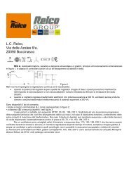
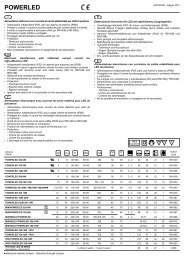
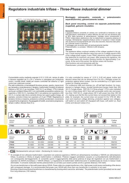
since 1967VTN06 - VTN10 - VTN16DATI TECNICI - TECHNICAL DATAFLUORESCENTI VARIALUCE - - FLUORESCENTDIMMERComando remoto – Pilotaggio (Potenziometrico, Amperometrico, Voltmetrico)- Alimentazione alternata <strong>trifase</strong> 400V + neutro 50/60Hz – Impostazionetensione min. e max. – Rampe di salita e discesa – Comandigalvanicamente isolati – Esecuzione a giorno senza protezione – Gradodi protezione IP00 – Raffreddamento naturale – Conforme alle direttiveEMC 89/336/CEE e BT 73/23/CEE + 93/68/CEE - Corrente nominale:VTN 06 = 6AVTN 10 = 10AVTN 16 = 16AImpieghiRegolazione: Velocità dei ventilatori con motori asincroni – Trasformatorielettromeccanici (toroidali e/o lamellari) – Potenza assorbita da elementiriscaldanti – Luminosità dei lampade ad incandescenza e/o alogene.Settori applicativiImpianti di aspirazione e ventilazione – Illuminotecnica.Fornitura: Nella fornitura sono compresi:n°1 Variatore elettronico di tensione - n°1 Libretto d’uso e manutenzione- n°1 Potenziometro con dado di fissaggio - n°1 Manopola di regolazione- n°1 Quadrante adesivoInstallazioneInstallare l’apparecchiatura con viti 5MA, lasciando lo pazio necessarioalla circolazione naturale dell’aria di raffreddamento. Effettuare i collegamentiin funzione del tipo di carico, rispettando gli schemi forniti.Per l’utilizzo con ventilatori vengono proposti due schemi di collegamentoFig.1 schema classico, Fig.2 con avvolgimento di avviamento sempreinserito, questa configurazione può in alcuni casi ridurre il ronziodel ventilatore, essendo però legato alle caratteristiche costruttive delmotore stesso non è possibile garantire tale riduzione di rumore. Obbligatoriamenteil collegamento del motre dovrà essere realizzato conconfigurazione a STELLA. Collegare il potenziometro ai morsetti 9-10tenendo presente che nel funzionamento voltmetrico e amperometrico ilmorsetto n°9 corrisponde al Positivo (+) ed il morsetto n°10 al Negativo(-). Il comando di marcia-arresto è sui morsetti 11-12.Messa in servizioAlimentare l’apparecchiatura e procedere alle regolazioni tenendo presenteche variando il potenziometro da zero al suo valore massimo siha una variazione solo se l’apparecchiatura è collegata sotto carico. Inassenza di carico si avrà sempre la massima tensione comunque si variil potenziometro.Selezione PilotaggioPredisporre i microinterruttori K1 secondo la tabella 1, in funzione deltipo di pilotaggio utilizzato.Comando di marcia e arrestoAlimentata l’apparecchiatura e dopo aver atteso circa due secondi affinchéil reset iniziale si esaurisca, si può abilitare o bloccare il funzionamentochiudendo o aprendo il collegamento ai morsetti 11 e 12. Inposizione chiusa (ON) si ha la marcia mentre in posizione aperta (OFF)si ha l’arresto. Se non si utilizza questa funzione ponticellare i morsetti11 e 12.Regolazione TrimmerMantenendo inalterata l’escursione del pilotaggio (SET POINT) e regolandoi trimmer P1 e P2, è possibile variare la tensione minima di partenzae il valore massimo della tensione di uscita. Nel campo così ottenutola tensione d’uscita varierà entro i limiti stabiliti dai trimmer.Tensione minima – Vu minPorre il pilotaggio a zero e ruotare il trimmer P1 in senso orario fino alvalore dei tensione desiderato sul carico (da 0 al 45%).Tensione Massima – Vu maxPorre il pilotaggio al 100% e ruotare il trimmer P2 in senso antiorario finoad ottenere una diminuzione della tensione in uscita al valore desiderato(da 95 al 55%).Dati Tecnici• Alimentazione <strong>trifase</strong>: 400V + N• Frequenza: 50/60Hz• Potenza Assorbita: 1W• Potenza dissipata: 1,5W/A• Isolamento comandi: non galvanico• Grado di protezione: IP00• Raffreddamento: naturale• Temperatura ambiente: da –35 a +45°C• Grado di umidità: minore del 90%• Pilotaggio: Potenziometrico 10Kohm 0,2W (lineare)• Voltmetrico: 0÷10Vcc 0,35mA• Amperometrico: 0÷20mA 500ohm• Amperometrico: 0÷20mA 180ohmRemote control - Pilot (Potentiometric, Amperometric, Voltmetric) - <strong>Three</strong>phase alternate power supply 400V + neutral 50/60Hz - Minimum andmaximum voltage settings - Incline and descent ramps - Control withgalvanic insulation - Day execution without protection - Protection gradeIP00 - Natural cooling - In compliance with EMC 89/336/EEC and BT73/23/EEC + 93/68/EEC Directives - Nominal currentVTN 06 = 6AVTN 10 = 10AVTN 16 = 16AUseDimming: Fans speed with as asynchronous motors, Electromechanicaltransformers (toroidal and/or laminated) - Absorbed power from heatedelements - Luminosity of incandescent and /or halogen lamps.Applicative sectorsFan and extractor systems – illumination engineering.SupplyThe following equipment is included:n°1 Electronic voltage <strong>dimmer</strong> - n°1 Use and maintenance manual -n°1 Potentiometer with fixing nut - n°1 Dimming knob - n°1 Adhesive dialInstallationInstall the appliance using 5MA screws. Leave the necessary space requiredfor natural circulation of cooling air. Connect according to the typeof load respecting the diagrams provided. Two connection diagrams areprovided for using the fans; Fig 1 classic diagram, Fig 2 with windingstart up always inserted. This last configuration can in some cases, reducethe fan buzzing. However, it is not possible to fully guarantee noisereduction due to the characteristics of the motor. Connect the potentiometerto terminals 9-10 taking into consideration the volumetric andamperometric function of terminal n°6 corresponding to Positive (+) andterminal n°7 corresponding to Negative (-). On - Off control and its terminals11-12.CommissioningPower the appliance and dim remembering that varying the potentiometerfrom zero to its maximum value can be carried out only if the applianceis connected under load. If no load is available, maximum voltage willalways be available even if the potentiometer is varied.Pilot selectionPredispose micro switch K1 according to table 1, in function with the typeof pilot to be used.On and Off controlPower the appliance and wait approximately two seconds for the initialreset to finish. The function can be enabled or blocked by closing andopening terminals 11 and 12. In the closed position (ON) the applianceoperates whilst in position (OFF) the appliance is stopped. If this functionis not used, jump terminals 11 and 12.Trimmer dimmingHolding the pilot (SET POINT) and regulating trimmers P1 and P2, it ispossible to vary the minimum starting voltage and the maximum outputvalue. In the field, the output voltage varies within the limits determinedby the trimmer.Minimum voltage – Vu min: Move the pilot to zero and rotate trimmerP1 anticlockwise up to the minimum desired value on the load (from 0to 45%).Maximum voltage – Vu max: Move the potentiometer pilot to 100% androtate trimmer P2 anticlockwise until the output voltage is reduced to thedesired value (from 95 to 55 %).Technical data• <strong>Three</strong> phase power supply: 400V + N• Frequency: 50/60Hz• Absorbed power: 1W• Dissipated Power: 1.5W/A• Insulation control: not galvanic• Protection degree: IP00• Cooling: natural• Ambient temperature: from –35 to +45°C• Humidity grade: less than 90%• Pilot: Potentiometric 10Kohm 0.2W (linear)• Voltmetric: 0÷10Vcc 0.35mA• Amperometric: 0÷20mA 500ohm• Amperometric: 0÷20mA 180ohm340 www.relco.it
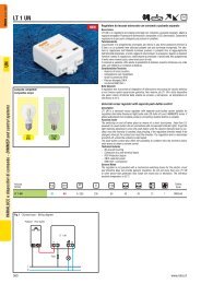
since 1967Fig. 1 Fig. 2RSTNRSTNVTN06 - VTN10 - VTN16K1VTN06 - VTN10 - VTN16K11 2 3 4 5 6 7 8 9 10 11 121 2 3 4 5 6 7 8 9 10 11 12MFig. 3 Fig. 4LNVTN06 - VTN10 - VTN16K11 2 3 4 5 6 7 8 9 10 11 12VTN06 - VTN10 - VTN16K11 2 3 4 5 6 7 8 9 10 11 121 2 3 4 5 6 7 8Jolly OmegaN L A BC1 C2Fig. 1VTN06 - VTN10 - VTN16Fig. 2VTN06 - VTN10 - VTN16VTN 06Corrente nominale - Nominal currentPotenza con carico resistivo - Power with resistive loadPotenza con carico induttivo - Power with inductive loadPotenza minima controllabileMinimum power that can be controlledVTN 10Corrente nominale - Nominal currentPotenza con carico resistivo - Power with resistive loadPotenza con carico induttivo - Power with inductive loadPotenza minima controllabileMinimum power that can be controlledVTN 16Corrente nominale - Nominal currentPotenza con carico resistivo - Power with resistive loadPotenza con carico induttivo - Power with inductive loadPotenza minima controllabileMinimum power that can be controlled6A4150W3700W50W10A6900W4700W50W16A11000W7800W50WRSTNFig. 3VTN06 - VTN10 - VTN16Fig. 4VTN06 - VTN10 - VTN16 - Comando a pulsante tramite interfaccia0÷10Vcc (Jolly Omega)VTN06 - VTN10 - VTN16 - Push button control with 0÷10Vcc interface(Jolly Omega)Selezione microinterruttori - K1 - ONMicro switch selection - K1 - ONPotenziometrico 10 Kohm 1/4WPotentiometric 10 Kohm 1/4WVoltmetrico 0÷10Vcc 0,6mAVoltmetric 0÷10Vcc 0,6mAAmperometrico 0÷20mA 500ohmAmperometric 0÷20mA 500ohmAmperometrico 0÷20mA 180ohmAmperometric 0÷20mA 180ohmP6 - SALITA partenza con tensione V min P5P6 - UP departure with tension V min P5P6 - SALITA partenza con tensione 0P6 - UP departure with tension 0P7 - DISCESA attivataP7 - DOWN activated1 2 3 4 5 6• •••••FLUORESCENTI VARIALUCE - - FLUORESCENTDIMMERP7 - DISCESA disattivataP7 - DISCESA disattivata•www.relco.it341