You also want an ePaper? Increase the reach of your titles
YUMPU automatically turns print PDFs into web optimized ePapers that Google loves.
During braking the disc has to dissipate the kinetic<br />
energy of the motorcycle which is normally turned<br />
into heat by the friction between the pads and the<br />
disc itself. Therefore, the latter is affected by a<br />
thermomechanic force (heat + force) that the disc<br />
naturally holds out without getting deformed.<br />
Every disc has its own inertia (i.e. the tendency of a<br />
body not to modify its motion status) which depends<br />
on the weight and the external diameter and affects<br />
the speed when shifting directions.<br />
A new disc project must take all these points into<br />
consideration and the best performance is achieved<br />
when the disc is lighter and more resistant.<br />
The combination of these discs with <strong>Brembo</strong> Z04<br />
pads won the 2009 and 2011World SuperSport<br />
Championship title.<br />
“T-Drive” disc concentrates the most recent <strong>Brembo</strong><br />
Racing technologies and knowhow, until now<br />
exclusive of MotoGP and SBK. A special “T” profile<br />
of the eight connections between rotor and drum is<br />
the innovation that makes “T-Drive” discs so<br />
different from traditional versions with cylindrical<br />
bushings. This particular coupling allows to transfer<br />
braking torque more efficiently and guarantees<br />
higher resistance to thermo-mechanical stresses.<br />
T-Drive system assures both radial and axial<br />
movements (full floating) for better performances<br />
and a weight reduction which gives a consistent<br />
improvement in bike handling. The new rotor is<br />
lighter (reduced height) and more efficient thanks<br />
to new position of holes with differentiated<br />
diameters. Also the drum concretely cooperates to<br />
the achievement of the best result: produced in<br />
aluminium alloy through CNC machining, has been<br />
projected to guarantee lightness and stiffness.<br />
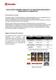
BREMBO RACING SUPERSPORT 5,5-mm discs are fully<br />
interchangeable with the original discs and they are<br />
designed to fit to the OE calipers as well as with<br />
BREMBO Racing. These are floating discs made up of<br />
a brake rotor in thermically-treated martensitic<br />
stainless steel (capable to stand any thermomechanic<br />
strain) and of an CNC alloy-aluminium bell.<br />
These two parts are connected to each<br />
other using 10 bushings.<br />
<strong>Brembo</strong> Racing <strong>Disc</strong>s<br />
Durante la frenata il disco dissipa l’energia cinetica<br />
della moto, attraverso il calore prodotto dall’attrito<br />
tra le pastiglie ed il disco stesso.<br />
Quest’ultimo viene quindi sollecitato da un’azione<br />
termomeccanica alla quale il disco deve resistere<br />
senza deformarsi permanentemente.<br />
Ogni disco è dotato della propria inerzia (tendenza<br />
di un corpo a non modificare il proprio stato di<br />
moto) dipendente da peso e diametro esterno, che,<br />
in pratica, influenza la rapidità nei cambi di direzione.<br />
Il progetto di un disco non può quindi prescindere<br />
da quanto sopra e sarà tanto migliore quanto più<br />
riuscirà a essere leggero e nel contempo resistente.<br />
Questi dischi, in combinazione con le pastiglie<br />
<strong>Brembo</strong> Z04, hanno vinto il Mondiale<br />
SuperSport 2009 e 2011.<br />
T-Drive <strong>Disc</strong> <strong>Disc</strong>o “T-Drive”<br />
Supersport <strong>Disc</strong><br />
Nato dall’esperienza maturata in SBK e MotoGP, il<br />
disco “T-Drive” presenta un nuovo accoppiamento<br />
tra fascia e campana, costituito da otto perni a “T”<br />
ricavati sul disco e da otto sagome sulla campana, che<br />
consente l’eliminazione dei nottolini di trascinamento.<br />
Questo sistema garantisce la trasmissione della<br />
coppia frenante in modo più efficace e migliora la<br />
resistenza agli stress termomeccanici.<br />
Il sistema “T-DRIVE” permette la flottanza sia radiale<br />
sia assiale e consente di ridurre il peso complessivo<br />
del disco, portando un consistente vantaggio nella<br />
guidabilità.<br />
La fascia è stata ottimizzata sia riducendone l’altezza<br />
(più leggerezza) sia ridistribuendo la disposizione dei<br />
fori (di diametro differenziato).<br />
Anche la campana contribuisce in maniera sostanziale<br />
al risultato finale: realizzata in lega leggera tramite<br />
lavorazioni CNC, è stata progettata per garantire<br />
leggerezza e rigidità.<br />
<strong>Disc</strong>o SuperSport<br />
I dischi SUPERSPORT sono intercambiabili agli<br />
originali e adatti a lavorare sia con le pinze di serie<br />
che con le BREMBO Racing. Sono dischi flottanti<br />
composti dalla fascia in acciaio martensitico<br />
termicamente trattato (in grado di resistere a qualsiasi<br />
sollecitazione termomeccanica) e dalla campana in<br />
lega d’alluminio CNC. L’accoppiamento tra i due<br />
componenti avviene per mezzo di<br />
10 nottolini di trascinamento.<br />
53<br />
1
1<br />
54<br />
T-Drive <strong>Disc</strong><br />
Technical Characteristics • Caratteristiche Tecniche<br />
Mounting / Fissaggio As Original / Come Originale<br />
Rotor Height / Altezza Fascia 32 mm.<br />
Rotor Thicknes / Spessore Fascia 5,5 mm.<br />
Rotor Material / Materiale Fascia Stainless Steel / Acciaio Inox<br />
Bell Material / Materiale Campana Aluminium Alloy / Lega Alluminio<br />
Connection Number / Numero Connessioni 8
Super Sport <strong>Disc</strong><br />
Technical Characteristics • Caratteristiche Tecniche<br />
Mounting / Fissaggio As Original / Come Originale<br />
Rotor Height / Altezza Fascia 34 mm.<br />
Rotor Thicknes / Spessore Fascia 5,5 mm.<br />
Rotor Material / Materiale Fascia Stainless Steel / Acciaio Inox<br />
Bell Material / Materiale Campana Aluminium Alloy / Lega Alluminio<br />
Connection Number / Numero Connessioni 10<br />
55<br />
1
1<br />
56<br />
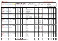
T-Drive and Supersport <strong>Disc</strong>s<br />
Applications Table<br />
Year<br />
Model From To <strong>Disc</strong> ø S. Sport <strong>Disc</strong>s T-Drive <strong>Disc</strong>s Note<br />
APRILIA<br />
RSV1000, RSV1000R 2000 2003 320 208.9737.25 208.A985.25 9<br />
RSV1000R 2004 2008 320 208.9737.25 208.A985.25 9<br />
RSV1000R Factory 2004 2007 320 208.9737.25 208.A985.25 9<br />
RSV4 / RSV4 Factory 2009 2011 320 208.9737.25 208.A985.25 9<br />
Tuono 2002 2006 320 208.9737.25 208.A985.25 9<br />
Tuono R 2006 2010 320 208.9737.25 208.A985.25 9<br />
Tuono V4 R 2011 2011 320 208.9737.25 208.A985.25<br />
Shiver 750<br />
BENELLI<br />
2007 2010 320 208.9737.10 208.A985.10 9<br />
TNT Sport 2005 2008 320 208.9737.10 208.A985.10 9<br />
TNT Cafè 2005 2008 320 208.9737.10 208.A985.10 9<br />
TNT Titanium 2005 2008 320 208.9737.10 208.A985.10 9<br />
Tornado 2006 2008 320 208.9737.10 208.A985.10 9<br />
TNT R160<br />
BIMOTA<br />
2011 2011 320 208.9737.10 208.A985.10<br />
DB7<br />
BMW<br />
2007 2008 320 208.9737.10 208.A985.10 9<br />
S1000RR<br />
DUCATI<br />
2009 2011 320 208.9737.51 N/A<br />
916 1994 1998 320 208.9737.10 208.A985.10 9<br />
996,998,excluding R models 1999 2003 320 208.9737.10 208.A985.10 9<br />
749,999 2003 2006 320 208.9737.11 208.A985.11 9<br />
999 R/S 2003 2006 320 208.9737.11 208.A985.11 9<br />
Monster S4R S 2003 2005 320 208.9737.10 208.A985.10 9<br />
Monster 696 2008 2010 320 208.9737.10 208.A985.10 9<br />
Monster 796 2010 2011 320 208.9737.36 208.A985.36<br />
Monster 1100 2009 2010 320 208.9737.36 208.A985.36 9<br />
Monster 1100 S 2009 2010 320 208.9737.11 208.A985.11 9<br />
Sport / GT 2009 2009 320 208.9737.10 208.A985.10<br />
848 / 848 evo 2008 2011 320 208.9737.11 208.A985.11 9<br />
1098 2007 2011 320 208.9737.11 208.A985.11<br />
1198 S / 1198 R 2009 2011 320 208.9737.11 208.A985.11<br />
1198 R Bayliss 2009 2009 320 208.9737.11 208.A985.11<br />
Streetfighter / Streetfighter S 2009 2011 320 208.9737.11 208.A985.11<br />
Multistrada 1200 2011 2011 320 208.9737.36 208.A985.36<br />
Diavel 1200<br />
HONDA<br />
2011 2011 320 208.9737.36 208.A985.36 9<br />
VTR 1000 SP1, SP2 (RC51) 2000 2006 320 208.9737.12 208.A985.12 9<br />
CBR 600 RR 2005 2011 320 208.9737.12 208.A985.12 10<br />
CBR 600 RR + ABS version 2003 2011 310 208.9737.46 208.A985.46 9<br />
CBR 1000 RR 2004 2005 310 208.9737.46 208.A985.46 9<br />
CBR 1000 RR 2004 2007 320 208.9737.12 208.A985.12 10<br />
CBR 1000 RR 2008 2008 320 208.9737.45 208.A985.45 9<br />
CBR 1000 RR (with & W/o ABS) 2009 2011 320 208.9737.45 208.A985.45 9<br />
CB1000 RR 2008 2011 310 208.9737.46 208.A985.46 9<br />
CB1000 RR 2008 2011 320 208.9737.12 208.A985.12
T-Drive and Supersport <strong>Disc</strong>s<br />
Applications Table<br />
Year<br />
Model From To <strong>Disc</strong> ø S. Sport <strong>Disc</strong>s T-Drive <strong>Disc</strong>s Note<br />
KAWASAKI<br />
ZX 6 R (600 cc) 2003 2004 300 208.9737.14 N/A 3-9<br />
ZX 6 R (636 cc) 2005 2006 300 208.9737.14 N/A 9<br />
ZX 6 RR (636 cc) 2003 2004 300 208.9737.14 N/A 3-9<br />
ZX 6 RR (600 cc) 2005 2011 300 208.9737.14 N/A 9<br />
ZX 6 RR (600 cc) 2005 2011 320 208.9737.22 208.A985.22 4<br />
ER-6N (650cc) 2006 2010 300 208.9737.14 N/A 9<br />
Z 750 2007 2011 300 208.9737.14 N/A 9<br />
Z 750 R 2011 2011 300 208.9737.14 N/A 9<br />
ZX 10 R 2004 2007 300 208.9737.14 N/A 9<br />
ZX 10 R 2004 2007 320 208.9737.22 208.A985.22 4<br />
ZX 10 R 2008 2010 310 208.9737.34 208.A985.34 9<br />
ZX 10 R 2008 2010 320 208.9737.22 208.A985.22 4-8<br />
ZX 10 R (ABS) 2011 2011 310 208.9737.34 208.A985.34 9<br />
ZX 10 R (ABS) 2011 2011 320 208.9737.22 208.A985.22<br />
Z 1000 2007 2011 300 208.9737.14 N/A 9<br />
Z 1000 SX 2011 2011 TBD 208.9737.14 N/A 9<br />
ZX 14 R 2006 2011 310 208.9737.34 208.A985.34 9<br />
ZX 14 R<br />
KTM<br />
2006 2011 320 208.9737.22 208.A985.22<br />
Supermoto 950 2005 2008 320 208.9737.10 208.A985.10<br />
LC8 SM / SD / SD-R / SM-T / SM-R 2009 2009 320 208.9737.10 208.A985.10<br />
990 Superduke 2005 2010 320 208.9737.10 208.A985.10 7-9<br />
RC8 / RC8-R<br />
MONDIAL<br />
2008 2011 320 208.9737.10 208.A985.10 9<br />
Piega Evo<br />
MOTO MORINI<br />
2004 2007 320 208.9737.10 208.A985.10<br />
Corsaro<br />
MV AUGUSTA<br />
2005 2007 320 208.9737.10 208.A985.10 9<br />
F3 675 2011 2011 320 208.9737.47 208.A985.47<br />
F4 750 S 2003 2007 310 208.9737.27 208.A985.27 9<br />
F4 -1000 S 2005 2007 310 208.9737.27 208.A985.27 9<br />
F4- 1000 R & Senna 2006 2007 320 208.9737.28 208.A985.28 9<br />
F4- 1078 2009 2010 320 208.9737.28 208.A985.28 9<br />
F4- RR / F4 RR Corsacorta 2011 2011 320 208.9737.28 208.A985.28 9<br />
Brutale S 2004 2005 310 208.9737.27 208.A985.27 9<br />
Brutale 910 2006 2007 310 208.9737.27 208.A985.27 9<br />
Brutale R 2006 2007 320 208.9737.28 208.A985.28 9<br />
Brutale 1078<br />
SUZUKY<br />
2009 2011 320 208.9737.28 208.A985.28 9<br />
GSX-R 600 2001 2003 320 208.9737.15 208.A985.15 9<br />
GSX-R 600 2004 2005 300 208.9737.16 N/A 9<br />
GSX-R 600 2006 2007 310 208.9737.17 208.A985.17 9<br />
GSX-R 600 2006 2007 320 208.9737.26 208.A985.26 5<br />
GSX-R 600 2008 2011 310 208.9737.32 208.A985.32 9<br />
GSX-R 600 2008 2011 320 208.9737.33 208.A985.33 12<br />
GSX-R 750 2000 2003 320 208.9737.15 208.A985.15 9<br />
57<br />
1
1<br />
58<br />
T-Drive and Supersport <strong>Disc</strong>s<br />
Applications Table<br />
Year<br />
Model From To <strong>Disc</strong> ø S. Sport <strong>Disc</strong>s T-Drive <strong>Disc</strong>s Note<br />
GSX-R 750 2004 2005 300 208.9737.16 N/A 9<br />
GSX-R 750 2006 2007 310 208.9737.17 208.A985.17 9<br />
GSX-R 750 2006 2007 320 208.9737.26 208.A985.26 5<br />
GSX-R 750 2008 2011 310 208.9737.32 208.A985.32 9<br />
GSX-R 750 2008 2011 320 208.9737.33 208.A985.33 12<br />
GSX-R 1000 2001 2002 320 208.9737.15 208.A985.15 9<br />
GSX-R 1000 2003 2004 300 208.9737.16 N/A 9<br />
GSX-R 1000 2005 2007 310 208.9737.17 208.A985.17 9<br />
GSX-R 1000 2005 2007 320 208.9737.26 208.A985.26 5<br />
GSX-R 1000 2008 2008 310 208.9737.17 208.A985.17 5-9<br />
GSX-R 1000 2008 2008 320 208.9737.26 208.A985.26 5<br />
GSX-R 1000 2009 2011 310 208.9737.32 208.A985.32 5-9<br />
GSX-R 1000 2009 2011 320 208.9737.33 208.A985.33 5<br />
Hayabusa 1999 2005 320 208.9737.15 208.A985.15 9<br />
Hayabusa 2006 2011 310 208.9737.35 208.A985.35 9<br />
B-King 2008 2011 310 208.9737.35 208.A985.35 9<br />
TRIUMPH<br />
Speed Triple 2004 2007 320 208.9737.23 208.A985.23 9<br />
Speed Triple 2008 2010 320 208.9737.37 208.A985.37 9-13<br />
Street Triple 2007 2009 310 208.9737.30 208.A985.30<br />
675 2006 2010 310 208.9737.30 208.A985.30<br />
675 R 2011 2011 310 208.9737.30 208.A985.30<br />
YAMAHA<br />
YZF-R6 1999 2002 300 208.9737.18 N/A 9<br />
YZF-R6 2003 2004 300 208.9737.19 N/A 9<br />
YZF-R6 2005 2011 310 208.9737.20 208.A985.20 9<br />
YZF-R6 2005 2011 320 208.9737.21 208.A985.21 11<br />
YZF-R6S 2006 2006 300 208.9737.19 N/A 9<br />
FZ6 2004 2008 300 208.9737.19 N/A 9<br />
XJ6 2009 2011 300 208.9737.19 N/A 9<br />
YZF-R1 1998 2003 300 208.9737.18 N/A 9<br />
YZF-R1 2004 2006 320 208.9737.21 208.A985.21 9<br />
YZF-R1 SP-LE 2006 2006 320 208.9737.24 208.A985.24 9<br />
YZF-R1 2007 2011 310 208.9737.20 208.A985.20 9<br />
YZF-R1 2007 2011 320 208.9737.21 208.A985.21 6<br />
FZ1 2006 2011 320 208.9737.21 208.A985.21 9<br />
MT-03 2006 2011 300 208.9737.19 N/A 9<br />
V- Max 2009 2011 320 208.9737.48 208.A985.21<br />
Specific Notes:<br />
2 - OEM disc diameter is 320mm, 310mm discs (208.9737.13) may be used by removing the spacers under the brake caliper<br />
3 - OEM disc diameter is 280mm, 300mm discs (208.9737.14) may be used by adding the spacers under the brake caliper<br />
4 - OEM disc diameter is 300mm, 320mm discs (208.9737.22) may be used by adding the spacers under the brake caliper<br />
5 - OEM disc diameter is 310mm, 320mm discs (208.9737.26) may be used by adding the spacers under the brake caliper<br />
9 - <strong>Disc</strong>s with ABE approval granted by the German Ministry of Transport on TÜV certification<br />
10 - OEM disc diameter is 310 mm , 320 mm discs (208.9737.12 ) may be used by adding the spacer under the OEM cal.<br />
11 - OEM disc diameter is 310 mm , 320 mm discs (208.9737.21 ) may be used by adding the spacer under the OEM cal.<br />
12 - OEM disc diameter is 310 mm , 320 mm discs (208.9737.33) may be used by adding the spacer under the OEM cal.
Moto 2 <strong>Disc</strong><br />
Code 108973740<br />
Technical Characteristics • Caratteristiche Tecniche<br />
<strong>Disc</strong> Diameter / Diametro <strong>Disc</strong>o 300 mm.<br />
Rotor Height / Altezza Fascia 34 mm.<br />
Rotor Thicknes / Spessore Fascia 5,5 mm.<br />
Rotor Material / Materiale Fascia Stainless Steel / Acciaio Inox<br />
Bell Material / Materiale Campana Aluminium Alloy / Lega Alluminio<br />
Connection Number / Numero Connessioni 10<br />
59<br />
1
1<br />
60<br />
SBK <strong>Disc</strong><br />
Technical Characteristics • Caratteristiche Tecniche<br />
Mounting / Fissaggio See next page / Vedi pagina successiva<br />
Rotor Height / Altezza Fascia 30 mm.<br />
Rotor Thicknes / Spessore Fascia 6 mm.<br />
Rotor Material / Materiale Fascia Stainless Steel / Acciaio Inox<br />
Bell Material / Materiale Campana Aluminium Alloy / Lega Alluminio<br />
Connection Number/ Numero Connessioni 12
SBK <strong>Disc</strong>s Dimensions Table<br />
Code Application <strong>Disc</strong> Inner Holes Holes Holes Offset Th.<br />
ø ø axis ø n° mm. mm.<br />
08670321 - 320 80,0 101,5 8,5 6 10,5 6,0<br />
08670343 - 290 58,0 74,0 6,25 6 17,0 5,5<br />
08670366 - 320 69,0 91,0 10,0 10 3,4 6,0<br />
08715066 G 320 69,0 91,0 10,2 5 0,0 6,0<br />
08715150 B 320 132,0 150,0 8,5 5 0,0 6,0<br />
08755010 C 320 94,0 110,0 6,5 6 13,0 6,0<br />
08755011 D 320 80,5 100,0 10,5 5 0,0 6,0<br />
08755012 E 320 100,0 120,0 10,5 5 0,0 6,0<br />
08755013 F 320 72,0 90,0 8,5 5 15,5 6,0<br />
08755014 I 320 80,0 101,5 8,5 5 7,5 6,0<br />
08755015 M 320 102,0 120,0 8,5 6 0,0 6,0<br />
08755016 A 320 64,0 80,0 8,5 6 10,5 6,0<br />
08755017 L 320 94,0 110,0 6,25 6 15,75 6,0<br />
08755018 H 320 72,0 90,0 8,5 5 10,0 6,0<br />
X952000 - 200 == 124,0 9,0 4 0,0 3,5<br />
VENTILATED RACING DISC<br />
08715034 - 218 69 86,0 8,2 3 12,0 8,0<br />
XA0J434/35 - 305 72 90,0 8,5 5 11,5 8,0<br />
Applications list • Applicazioni<br />
A > Aprilia RSV 1000 (all versions) - RSV4<br />
Ducati 748 - 916 - 996 - 998<br />
B > Yamaha R6 ‘05 > / R1 ‘04 ><br />
Original disc diameter 310 / 320 mm.<br />
C > Honda CBR 600RR ‘05 > / 1000RR ‘04 ><br />
Original disc diameter 310 / 320 mm.<br />
D > Kawasaki ZX 10R ‘04 > / ZX 6R ‘05 / ‘06 e ZX 6RR ‘05 ><br />
Original disc diameter 300 mm.<br />
E > Suzuki GSX 600R ‘06- GSX 750R ‘06 - GSX 1000R ‘05 ><br />
Original disc diameter 310 mm.<br />
F > Ducati 749 / 999<br />
(All versions / Tutte e versioni)<br />
<strong>Disc</strong> Diameter<br />
Centering Diameter<br />
G > Suzuki GSX 600R ‘97/’03 - GSX 750R ‘96/’03 -<br />
GSX 1000R ‘01/’02<br />
Original disc diameter 320 mm.<br />
Suzuki GSX 600R ‘04/’05 - GSX 750R ‘04/’05 -<br />
GSX 1000R ‘03/’04<br />
Original disc diameter 300 mm.<br />
H > DUCATI 999 RS (SBK clienti) - 1089 RS<br />
I > MV Agusta F4 750 - F4 1000 - Brutale 750/910<br />
L > Honda CBR 1000RR ‘08<br />
M > Suzuki GSX 1000 R ‘09 ><br />
Original disc diameter 300 mm.<br />
Holes<br />
Axis<br />
Holes<br />
Diameter<br />
Off-set<br />
Th.<br />
61<br />
1
1<br />
62<br />
Spacer Kits for Original <strong>Disc</strong> Diameter<br />
Kit Distanziali per Diametri <strong>Disc</strong>hi Originali<br />
Spacers Code for Spacers Code for<br />
<strong>Disc</strong> Ø T-Drive SuperSport Caliper 220A01610 Caliper 220A39710<br />
Model Year OEM P/N P/N and 220A80310 and 220B01010<br />
HONDA<br />
CBR 600 RR ‘05 - ‘12 310 208A98546 208973746 105998709 N/A<br />
CBR 1000 RR ‘04 - ‘05 310 208A98513 208973713 105998709 N/A<br />
CBR 1000 RR ‘06 - ‘07 320 208A98512 208973712 105998709 105998709 rem. OE spacer<br />
CBR 1000 RR ‘08 - ‘12 320 208A98545 208973745 105998709 105998709 rem. OE spacer<br />
KAWASAKI<br />
ZX 6 R ‘05 - ‘12 300 208A98514 208973714 220A02411 105998709<br />
ZX 10 R ‘04 - ‘07 300 208A98514 208973714 220A02411 105998709<br />
ZX 10 R ‘08 - ‘10 310 208A98534 208973734 220A06127 220A06117<br />
ZX 10 R (+ ABS) ‘11 - ‘12<br />
SUZUKI<br />
310 208A98534 208973734 220A06127 220A06117<br />
GSX R 600/750 ‘04 - ‘05 300 208A98516 208973716 220A02411 105998709<br />
GSX R 600/750 ‘06 - ‘07 310 208A98517 208973717 220A06127 220A06117<br />
GSX R 600/750 ‘08 - ‘12 310 208A98532 208973732 220A06127 220A06117<br />
GSX R 1000 ‘03 - ‘04 300 208A98516 208973716 220A02411 105998709<br />
GSX R 1000 ‘05 - ‘08 310 208A98517 208973717 220A06127 220A06117<br />
GSX R 1000 ‘09 - ‘12 310 208A98517 208973717 220A02431 220A02421<br />
Hayabusa<br />
TRIUMPH<br />
‘08 - ‘11 310 208A98535 208973735 220A02431 220A02421<br />
Daytona 675 ‘09 - ‘11 310 208A98523 208973723 220A02425 220A02415<br />
Speed Tr. 1050<br />
YAMAHA<br />
‘05 - ‘07 320 208A98523 208973723 220A06127 220A06117<br />
YZF R6 ‘05 - ‘12 310 208A98520 208973720 220A06125 220A06115<br />
YZF R1 ‘04 - ‘06 320 208A98521 208973721 220A06125 220A06115<br />
Spacer Kits for Upgrade <strong>Disc</strong><br />
Kit Distanziali per <strong>Disc</strong>hi Maggiorati<br />
Spacers Code for Spacers Code for<br />
Upgrade T-Drive SuperSport Caliper 220A01610 Caliper 220A39710<br />
Model Year <strong>Disc</strong> Ø P/N P/N and 220A80310 and 220B01010<br />
HONDA<br />
CBR 600 RR ‘05 - ‘12 320 208A98512 208973712 220A02411 105998709<br />
CBR 1000 RR<br />
KAWASAKI<br />
‘04 - ‘05 320 208A98512 208973712 220A02411 105998709<br />
ZX 6 R ‘05 - ‘12 320 208A98522 208973722 220A02431 220A02421<br />
ZX 10 R ‘04 - ‘07 320 208A98522 208973722 220A02431 220A02421<br />
ZX 10 R ‘08 - ‘10 320 208A98522 208973722 220A06137 220A06177<br />
ZX 10 R (+ ABS) ‘11 - ‘12<br />
SUZUKI<br />
320 208A98522 208973722 220A06137 220A06177<br />
GSX R 600/750 ‘06 - ‘07 320 208A98526 208973726 220A06137 220A06177<br />
GSX R 600/750 ‘08 - ‘10 320 208A98533 208973733 220A06137 220A06177<br />
GSX R 1000 ‘05 - ‘08 320 208A98526 208973726 220A06137 220A06177<br />
GSX R 1000<br />
YAMAHA<br />
‘09 - ‘12 320 208A98533 208973726 N/A 220A06277<br />
YZF R6 ‘05 - ‘12 320 208A98521 208973721 220A06135 220A06175
<strong>Motard</strong> ard <strong>Disc</strong><br />
Technical cal Characteristics s<br />
• Caratteristiche Tecniche<br />
Mounting - off-set / Fissaggio - off-set As Original / Come Originale<br />
Rotor Height / Altezza Fascia 34 mm.<br />
Rotor Thickness / Spessore Fascia 5,5 mm.<br />
Rotor Material / Materiale Fascia Stainless Steel / Acciaio Inox<br />
Bell Material / Materiale Campana Aluminium Alloy / Lega Alluminio<br />
Bushing Number / n° Nottolini 10<br />
69<br />
2
2<br />
70<br />
<strong>Motard</strong> disc application list<br />
Year<br />
Model From To Code<br />
APRILIA<br />
SXV 450 ‘05 ‘12 108.A642.15<br />
SXV 550<br />
HONDA<br />
‘05 ‘12 108.A642.15<br />
CRF R 250 ‘04 ‘12 108.A642.11<br />
CRF X 250 ‘04 ‘12 108.A642.11<br />
CRF R 450 ‘02 ‘12 108.A642.11<br />
CRF X 450<br />
HONDA-HM<br />
‘04 ‘12 108.A642.11<br />
CR E Superm. 125 ‘00 ‘08 108.A642.11<br />
CR E Superm. 250 ‘00 ‘09 108.A642.11<br />
CRF R Superm. 250 ‘04 ‘08 108.A642.11<br />
CRF Superm. 450 ‘02 ‘03 108.A642.11<br />
CRF X Superm. 450<br />
KTM<br />
‘04 ‘09 108.A642.11<br />
SMR 450 ‘04 ‘08 108.A642.12<br />
SMR 525 ‘04 ‘05 108.A642.12<br />
DUKE 620 ‘95 ‘98 108.A642.12<br />
LC4 SC Superc. 620 ‘98 ‘04 108.A642.12<br />
LC4 Supermoto 620 ‘99 ‘01 108.A642.12<br />
LC4 SC Superc. 625 ‘02 108.A642.12<br />
LC4 Supermoto 625 ‘99 ‘04 108.A642.12<br />
SMC 625 ‘05 ‘08 108.A642.12<br />
DUKE II 640 ‘99 ‘02 108.A642.12<br />
DUKE-E 640 ‘98 108.A642.12<br />
LC4 Adventure 640 ‘01 ‘03 108.A642.12<br />
LC4 Enduro 640 ‘99 ‘07 108.A642.12<br />
LC4 Supermoto 640 ‘98 ‘07 108.A642.12<br />
SMC 660 ‘03 ‘07 108.A642.12<br />
Supermoto 690 ‘07 ‘08 108.A642.12<br />
Year<br />
Model From To Code<br />
SUZUKI<br />
RMZ 250 ‘07 ‘12 108.A642.14<br />
RMX 450 ‘10 ‘11 108.A642.14<br />
RMZ 450<br />
KAWASAKI<br />
‘05 ‘12 108.A642.14<br />
KX F 250 ‘06 ‘12 108.A642.17<br />
KLX R 450 ‘07 ‘12 108.A642.17<br />
KX F 450<br />
SUZUKI<br />
‘06 ‘12 108.A642.17<br />
RM SM 125 ‘05 ‘06 108.A642.18<br />
RMX S 250 ‘92 ‘98 108.A642.18<br />
DRZ E/S400 ‘00 ‘08 108.A642.18<br />
DRZ SM 400<br />
YAMAHA<br />
‘05 ‘09 108.A642.18<br />
WR F 250 ‘01 ‘12 108.A642.18<br />
YZ F 250 ‘01 ‘12 108.A642.18<br />
WR F 450 ‘03 ‘12 108.A642.18<br />
YZ F 450 ‘03 ‘12 108.A642.18
Mx / Enduro<br />
Oversize Kit<br />
Technical Characteristics • Caratteristiche Tecniche<br />
Mounting / Fissaggio As Original / Come Originale<br />
Rotor Diameter / Diametro <strong>Disc</strong>o 267 mm.<br />
Rotor Height / Altezza Fascia 27 mm.<br />
Rotor Thickness / Spessore Fascia 3 mm.<br />
Rotor Material / Materiale Fascia Stainless Steel / Acciaio Inox<br />
Bell Material / Materiale Campana Aluminium Alloy / Lega Alluminio<br />
Bushing Number / n° Nottolini 6<br />
Bracket Material / Materiale Staffa CNC Aluminium / Alluminio CNC<br />
Pads Compound / Mescola Pastiglia Sinter SX / Sinterizzata SX<br />
79<br />
3
3<br />
80<br />
Oversize Kit<br />
Applications List<br />
Year Oversize Pad Floting<br />
Model From To <strong>Disc</strong> ø Kit Code SetCode <strong>Disc</strong>o<br />
APRILIA<br />
RXV 450 2005 2011 267 122.B069.25 07KA17SX 08.A642.55<br />
RXV 550<br />
HONDA<br />
2005 2011 267 122.B069.25 07KA17SX 08.A642.55<br />
CRF R 250 2004 2012 267 122.B069.21 07KA17SX 08.A642.51<br />
CRF R 450 2004 2012 267 122.B069.21 07KA17SX 08.A642.51<br />
CRF X 450<br />
KTM<br />
2004 2012 267 122.B069.21 07KA17SX 08.A642.51<br />
EXC 125 2004 2009 267 122.B069.22 07BB04SX 08.A642.52<br />
SX - SXS 125 2000 2006 267 122.B069.22 07BB04SX 08.A642.52<br />
SX - SXS 125 2008 2010 267 122.B069.22 07BB04SX 08.A642.52<br />
EXC - EXC F - EXC G 250 2004 2009 267 122.B069.22 07BB04SX 08.A642.52<br />
XC F 250 2007 2009 267 122.B069.22 07BB04SX 08.A642.52<br />
EXC G 450 2004 2009 267 122.B069.22 07BB04SX 08.A642.52<br />
SX - F 350 2011 2011 267 122.B069.22 07BB04SX 08.A642.52<br />
XC F 450 2007 2009 267 122.B069.22 07BB04SX 08.A642.52<br />
SXS - SXS F 450<br />
HUSQVARNA<br />
2003 2008 267 122.B069.22 07BB04SX 08.A642.52<br />
CR 125 2005 2012 267 122.B069.26 07BB04SX 08.A642.56<br />
WR 125 2006 2012 267 122.B069.26 07BB04SX 08.A642.56<br />
CR 250 2005 2012 267 122.B069.26 07BB04SX 08.A642.56<br />
TC 250 2005 2012 267 122.B069.26 07BB04SX 08.A642.56<br />
WR 250 2005 2010 267 122.B069.26 07BB04SX 08.A642.56<br />
TCX 250 2011 267 122.B069.26 07BB04SX 08.A642.56<br />
TCX 300 2005 2012 267 122.B069.26 07BB04SX 08.A642.56<br />
TCX 310 2011 267 122.B069.26 07BB04SX 08.A642.56<br />
TC 450 2005 2010 267 122.B069.26 07BB04SX 08.A642.56<br />
TE 450 2006 2010 267 122.B069.26 07BB04SX 08.A642.56<br />
TC 510 2005 2009 267 122.B069.26 07BB04SX 08.A642.56<br />
TE 510<br />
KAWASAKI<br />
2006 2010 267 122.B069.26 07BB04SX 08.A642.56<br />
KX 250 2006 2010 267 122.B069.27 07KA17SX 08.A642.57<br />
KXF 250 / 450 2006 2012 267 122.B069.27 07KA17SX 08.A642.57<br />
KLX R 450<br />
SUZUKI<br />
2007 2012 267 122.B069.27 07KA17SX 08.A642.57<br />
RMZ 250 2007 2012 267 122.B069.24 07KA17SX 08.A642.54<br />
RMZ 450<br />
YAMAHA<br />
2005 2012 267 122.B069.24 07KA17SX 08.A642.54<br />
WRF 250 2003 2012 267 122.B069.28 07KA17SX 08.A642.58<br />
WRF 450 2003 2012 267 122.B069.28 07KA17SX 08.A642.58<br />
YZF 250 2006 2007 267 122.B069.28 07KA17SX 08.A642.58<br />
YZF 450 2006 2007 267 122.B069.28 07KA17SX 08.A642.58<br />
YZF 250 2008 2012 267 122.B069.A8 07YA47SX 08.A642.58<br />
YZF 450 2008 2012 267 122.B069.A8 07YA47SX 08.A642.58
2<br />
2<br />
<strong>Brembo</strong>. Number One<br />
for brakes.<br />
<strong>Brembo</strong> is the world’s leading<br />
maker of braking systems for<br />
motor cars, motorcycles and<br />
commercial vehicles. Today the<br />
company operates in 15 countries<br />
of 3 continents, with 35<br />
production and business sites.<br />
Research never ceases.<br />
<strong>Brembo</strong> has always invested in<br />
R&D, in its quest to offer a product<br />
at the leading edge, guaranteeing<br />
safety and performance. The<br />
<strong>Brembo</strong> Group has over 6,700<br />
collaborators,nearly 10% of whom<br />
are engineers and product<br />
specialists involved in research and<br />
development.<br />
<strong>Brembo</strong>, racing, and winning.<br />
For 30 years and more, <strong>Brembo</strong> has<br />
been equipping the cars and bikes<br />
of elite drivers and riders<br />
competing in motor sports at<br />
world championship level.<br />
<strong>Brembo</strong> - all done in-house.<br />
The entire manufacturing process<br />
is an in-house operation: design,<br />
development, testing, machining,<br />
quality control, distribution,<br />
service.<br />
<strong>Brembo</strong> High Performance<br />
The experience accumulated<br />
through years of intensive research<br />
in the competition field has<br />
allowed us to create product lines<br />
that are differentiated on the basis<br />
of the application types and<br />
different research and<br />
development procedures adopted.<br />
Thanks to the results obtained,<br />
motorbike sports enthusiasts who<br />
insist on replacing original brake<br />
systems with <strong>Brembo</strong> High<br />
Performance equipment are able<br />
to improve their riding style in<br />
terms of performance and safety<br />
while also ramping up the overall<br />
aesthetic appeal of their machines.<br />
For any further explanations please refer<br />
to our website www.brembo.com<br />
Racing and HP brake upgrade sections
<strong>Brembo</strong> è il leader dei freni.<br />
<strong>Brembo</strong> è leader mondiale dei<br />
sistemi frenanti per auto, moto e<br />
veicoli commerciali.<br />
L’azienda opera oggi in 15 Paesi di<br />
3 continenti, con 35 stabilimenti e<br />
siti commerciali.<br />
La ricerca non si ferma mai.<br />
Da sempre, <strong>Brembo</strong> investe in<br />
Ricerca e Sviluppo, per realizzare<br />
un prodotto all’avanguardia,<br />
sicuro e performante. Il Gruppo<br />
conta sulla collaborazione di oltre<br />
6.700 collaboratori, di cui circa il<br />
10% è composto da ingegneri e<br />
specialisti di prodotto che lavorano<br />
nella ricerca e sviluppo.<br />
<strong>Brembo</strong> vince nel racing.<br />
Da più di 30 anni, <strong>Brembo</strong><br />
equipaggia le auto e le moto dei<br />
grandi piloti nelle più importanti<br />
gare mondiali di automobilismo e<br />
motociclismo.<br />
Tutto è prodotto in <strong>Brembo</strong>.<br />
Tutto il processo produttivo è<br />
integrato all’interno dell’azienda:<br />
progettazione, sviluppo, test,<br />
lavorazione, controllo qualità,<br />
distribuzione, assistenza.<br />
<strong>Brembo</strong> High Performance e<br />
Racing.<br />
L’esperienza accumulata in anni di<br />
intensa attività agonistica, unita<br />
alla continua attività di ricerca, ha<br />
portato <strong>Brembo</strong> a sviluppare linee<br />
di prodotto differenziate in<br />
funzione della tipologia di<br />
applicazione.<br />
Grazie ai risultati ottenuti, gli<br />
appassionati di moto possono ora<br />
sostituire i sistemi frenanti di<br />
primo equipaggiamento con<br />
componenti <strong>Brembo</strong> High<br />
Performance o Racing, apportando<br />
notevoli miglioramenti alle proprie<br />
prestazioni e sicurezza di guida, ed<br />
all’aspetto estetico dei propri<br />
mezzi.<br />
Per ogni ulteriore informazione consultate<br />
il sito www.brembo.com<br />
sezioni Racing e HP brake upgrade<br />
3<br />
3
4<br />
1. SCOPE<br />
To show the correct procedures for the mounting<br />
and use of BREMBO front braking systems for<br />
racing motorcycles.<br />
2. RESERVOIR<br />
2.1. Choice of the reservoir<br />
The capacity of the reservoir must be such that when<br />
the brake fluid is between the MIN and MAX levels<br />
(with the cover in a horizontal position) the volume is<br />
at least equal to that required by the brake pistons in<br />
case of maximum pad and rotor wear.<br />
2.2. Mounting the reservoir<br />
a. The reservoir must be mounted on the<br />
motorcycle in such a way that with the<br />
motorcycle in a vertical position, the reservoir<br />
upper border in horizontal.<br />
b. With the motorcycle in a vertical position, the MIN<br />
level indication on the reservoir must be higher<br />
than the master cylinder fluid inlet pipe fitting.<br />
2.3. Inspections<br />
Verify that the brake fluid can flow freely within<br />
the reservoir, from the upper border down to the<br />
MIN level. This happens when air can flow from the<br />
exterior to the inside of the reservoir membrane (if<br />
this air flow is hampered, a vacuum could be<br />
created and this would not allow fluid to flow<br />
downwards). The popular bands that are usually<br />
wrapped around brake fluid reservoirs (if they are<br />
too close to the reservoir cover) could hamper this<br />
“breathing” of the reservoir and thus the mastercylinder<br />
would not be fed properly.<br />
3. MASTER-CYLINDER<br />
3.1. Mounting<br />
a. Mount the master-cylinder to the handlebar<br />
keeping in mind that it can be positioned in any<br />
manner requested by the driver.<br />
b. Adjust the lever distance from the handlebar by<br />
turning the adjusting nut either clockwise or<br />
anticlockwise according to the driver’s<br />
requirements; it must be noted that the lever<br />
positioning must allow the driver to generate the<br />
pressure necessary to stop the motorcycle.<br />
3.2. Inspections<br />
Pull the lever until it touches the grab handle on<br />
the handlebar and verify that the master-cylinder<br />
piston stroke is smooth.<br />
4. STEEL DISCS<br />
4.1. Mounting<br />
a. Verify that the disc bell and wheel mounting<br />
faces are free from burrs and dents, otherwise<br />
these surfaces should be reconditioned.<br />
b. The disc must fit onto the wheel easily.<br />
c. The disc must be mounted onto the wheel by<br />
using bolts having a diameter which corresponds<br />
to the holes in the mounting bell; the bolts must<br />
be of the quantity and length 2/7 as prescribed<br />
by the motorcycle manufacturer and must be<br />
tightened at the appropriate torque.<br />
d. It is suggested to apply thermal paints on the<br />
disc outer circumference in order to monitor<br />
operating temperatures.<br />
1. SCOPO<br />
Descrivere le corrette procedure per il montaggio e<br />
l’uso degli impianti frenanti dedicati alle<br />
competizioni.<br />
2. SERBATOIO OLIO<br />
2.1. Scelta del serbatoio<br />
La capacità del serbatoio deve essere tale da<br />
garantire che il livello del fluido freno scenda dal<br />
MAX. e non oltre il MIN., anche in caso di consumo<br />
massimo sia delle pastiglie che del disco.<br />
2.2. Montaggio serbatoio<br />
a. Il serbatoio deve essere montato in maniera tale<br />
da risultare verticale quando la motocicletta si<br />
trova in posizione di marcia.<br />
b. Con la motocicletta in ordine di marcia, la tacca<br />
di MIN. del serbatoio deve trovarsi al di sopra<br />
del punto d’ingresso olio nella pompa.<br />
2.3 Ispezioni<br />
Verificare che l’olio possa liberamente fluire<br />
attraverso il serbatoio.<br />
Può accadere che il passaggio aria permesso dalla<br />
membrana posta sotto il tappo s’interrompa,<br />
generando così una sorta di “effetto vuoto” che<br />
impedisce questo passaggio.<br />
Attenzione alle classiche bande in spugna poste sul<br />
serbatoio stesso: queste non devono essere poste<br />
troppo vicine al tappo di chiusura, potrebbero<br />
impedire all’aria di entrare.<br />
3. POMPA FRENO<br />
3.1. Montaggio<br />
a. Montare la pompa sul manubrio verificando che<br />
non ci siano impedimenti alla possibilità di<br />
ruotarla ed adeguarla alle necessità del pilota.<br />
b. Regolare la distanza della leva dal manubrio,<br />
agendo sull’apposito registro, in modo che il<br />
pilota abbia il giusto feeling con il freno.<br />
3.2. Ispezioni<br />
Azionare la leva freno a fondo, fino a farla toccare<br />
contro il manubrio, in modo da verificare che il<br />
pistoncino della pompa faccia tutta la corsa con<br />
movimento “morbido”, senza impuntamenti di<br />
sorta.<br />
4. DISCHI IN ACCIAIO<br />
4.1. Montaggio<br />
a. Controllare che non ci siano bave o altri residui<br />
di lavorazione tra le facce d’accoppiamento della<br />
ruota e della campana del disco.<br />
b. Il disco deve montare sulla ruota facilmente.<br />
c. I fori di fissaggio del disco devono avere un<br />
diametro adeguato alla vite, le viti devono essere<br />
della qualità e della lunghezza adeguata al<br />
lavoro che devono svolgere ed il loro serraggio<br />
effettuato con una chiave dinamometrica, tarata<br />
in maniera corretta.<br />
d. È consigliabile applicare le vernici termoviranti<br />
in modo da controllare la temperatura<br />
d’esercizio.
4.2. Inspections<br />
The disc must be “floating” even after it has<br />
been mounted onto the wheel: axial clearance<br />
between disc and bell must be 0.2 mm MIN.<br />
4.3. Note<br />
The discs must not be subjected to mechanical<br />
shock, and must not be contaminated with<br />
liquids, oil and grease.<br />
5. CALIPERS<br />
5.1. Mounting<br />
a. Mount the caliper onto the fork such that the<br />
arrow marked on the outer half-caliper<br />
corresponds to the forward direction of<br />
rotation of the brake disc (the disc must enter<br />
the caliper through the side corresponding to<br />
the smaller piston and exit through the other<br />
side corresponding to the larger piston).<br />
b. The caliper must be mounted in a symmetrical<br />
position with respect to the disc center line:<br />
Misalingment must be 0.15 mm MAX (see<br />
fig. 1).<br />
Fig.2<br />
c = d : 0,4 mm MAX<br />
/<br />
c. The clearance between disc outer circumference<br />
and caliper bridge must be 2 mm MIN (see fig. 2).<br />
d. The caliper mounting bolts must be tightened to<br />
the prescribed torque.<br />
e. Apply thermal tape on the internal half-caliper in<br />
order to monitor operating temperatures: these<br />
can be supplied by BREMBO under part number<br />
R 02.5168.11/12 (for the application area see<br />
fig. 3).<br />
f. Overheated calipes should be<br />
overhauled.<br />
6. PADS FOR STEEL DISCS<br />
6.1. Mounting<br />
a. The pads must be inserted inside the caliper<br />
without any interference and without requiring<br />
any excessive force.<br />
b. The pads must not protrude from the disc; the disc<br />
may protrude from the pads by 0,5 mm. MAX (see<br />
fig. 4 and fig. 5); to obtain the correct positioning<br />
of the caliper, as described above, it can be moved<br />
relative to the fork by using the existing clearance<br />
between the fixing holes and the caliper bolts.<br />
6.2. Inspection<br />
Verify that the pad pin and cotter pin have been<br />
correctly installed; it is suggested to tie the pad pin<br />
to the caliper and pads with iron wire through the<br />
appropriate holes.<br />
Fig.1<br />
a = b : 0,3 mm MAX<br />
/<br />
x<br />
a<br />
m<br />
5<br />
.<br />
0<br />
Fig.4<br />
Fig.5<br />
4.2. Ispezioni<br />
Il disco deve poter flottare liberamente dopo il<br />
montaggio. La flottanza minima deve essere di<br />
0,2 mm.<br />
4.3. Note<br />
Il disco non deve essere stato soggetto a shock<br />
meccanici oppure contaminato da liquidi corrosivi,<br />
olio o grasso.<br />
5. PINZE<br />
5.1. Montaggio<br />
a. Montare le pinze in modo che la freccia marcata<br />
sulla parte esterna della pinza sia in fase con il<br />
senso di rotazione della ruota (nel caso di pistoni<br />
differenziati il disco deve “entrare” del lato del<br />
pistoncino di diametro inferiore e,<br />
conseguentemente, uscire da quello di diametro<br />
maggiore).<br />
b. La pinza deve essere montata in modo che il suo<br />
asse di mezzeria corrisponda con quello del<br />
disco (vedi fig. 1). È ammesso undisallineamento<br />
max. di 0,15 mm.<br />
Fig.3<br />
c. La distanza tra il diametro esterno del disco ed i lati<br />
della pinza deve essere almeno di 2 mm., (vedi figura 2).<br />
d. Le viti di fissaggio della pinza devono essere<br />
serrate con la chiave dinamometrica alla coppia<br />
prescritta.<br />
e. Applicare all’interno della pinza (vedi figura 3)<br />
gli adesivi indicatori della temperatura max.<br />
raggiunta (thermo tape), in modo da monitorare<br />
la temperatura d’esercizio.<br />
f. Le pinze portate in sovratemperatura<br />
devono essere revisionate.<br />
6. PASTIGLIE PER DISCHI IN<br />
ACCIAIO<br />
6.1. Montaggio<br />
a. Le pastiglie devono poter essere inserite nella<br />
pinza senza interferenza e senza dover applicare<br />
una forza eccessiva.<br />
b. Le pastiglie, una volta montate, non devono<br />
fuoriuscire oltre il diametro esterno del disco bensì<br />
starne al di sotto di circa 0,5 mm. Per ottenere questa<br />
posizione si sfrutta il gioco esistente tra i bulloni<br />
di fissaggio ed i fori sul supporto (vedi figure 4/5).<br />
6.2. Ispezione<br />
Verificate che il perno di sostegno pastiglie e la<br />
copiglia di ritegno siano correttamente montati.<br />
Suggeriamo di mettere i vari componenti in<br />
sicurezza utilizzando filo di ferro passato negli<br />
appositi fori.<br />
5
6<br />
7. RESERVOIR TO MASTER-<br />
CYLINDER CONNECTION<br />
7.1. Choice of tubing<br />
Black rubber tubing, compatible with brake fluid,<br />
could be used; transparent plastic tubing could also<br />
be used: The rubber tubing is the better solution, but<br />
it is not possible to see through it, and so you could<br />
not see possible air bubbles; the transparent plastic<br />
tubing is better in this sense but since it is not<br />
compatible with brake fluid, sweating could occur<br />
and so it would have to be changed periodically.<br />
7.2. Mounting<br />
The tube must connect the reservoir outlet with the<br />
master-cylinder inlet; the appropriate hose clamps<br />
must be used at both ends.<br />
8. MASTER-CYLINDER/CALIPER<br />
CONNECTION<br />
8.1. Choice of tubing<br />
a. It is suggested to use teflon flexible tubing with<br />
steel-braided covering.<br />
b. The flexible tubing must have an internal diameter<br />
of 3 mm MIN.<br />
8.2. Mounting<br />
a. Pipe fittings must be tightened to the prescribed<br />
torque.<br />
b. The copper or aluminium washers can only be<br />
used once.<br />
9. BRAKE FLUID<br />
9.1. Choice<br />
a. Use only high boiling point DOT 3 or DOT 4 brake<br />
fluids.<br />
b. Use only brake fluid from a new and sealed<br />
container.<br />
c. Change brake fluid before each race.<br />
9.2. Notes<br />
Use of liquids other than brake fluids will damage<br />
the braking system components.<br />
10. BRAKING SYSTEM BLEEDING<br />
10.1. Procedure<br />
To bleed the brakes proceed as follows:<br />
a. Turn the handlebar until the border of the reservoir<br />
is horizontal.<br />
b. Fill the reservoir with brake fluid ; during bleeding<br />
avoid letting the brake fluid level go below the<br />
MIN level.<br />
c. Apply the brakes several times to fill the braking<br />
system partially.<br />
d. Insert a flexible transparent tube to the bleed<br />
screw.<br />
e. Bleed through one bleed screw at a time:<br />
• Pull the brake lever all the way and keep it in<br />
this position;<br />
flow out (initially only air will comeout) and then<br />
tighten the bleed screw (lightly);<br />
• Let go the brake lever, wait a few seconds and<br />
repeat the above steps until no air bubbles will<br />
come out of the bleed screw.<br />
f. Tighten the bleed screw to the prescribed torque<br />
and fill up the reservoir with brake fluid.;<br />
7. COLLEGAMENTO SERBATOIO<br />
OLIO/POMPA<br />
7.1. Scelta del tubo<br />
Utilizzare il tubo in gomma nera compatibile con il<br />
fluido freni. I tubi trasparenti sono raramente<br />
compatibili con il fluido freni e se utilizzati, devono<br />
essere sostituiti periodicamente.<br />
7.2. Montaggio.<br />
Il tubo deve collegare l’uscita del serbatoio con<br />
l’entrata della pompa, appropriate fascette<br />
stringitubo devono essere utilizzate alle due<br />
estremità.<br />
8. COLLEGAMENTO POMPA/<br />
PINZA<br />
8.1. Scelta del tubo<br />
a. Suggeriamo fortemente di utilizzare tubazioni con<br />
l’interno in teflon e con l’esterno rivestito in<br />
maglia d’acciaio.<br />
b. Il diametro della tubazione interna deve essere<br />
almeno di 3 mm.<br />
8.2. Montaggio<br />
a. I bocchettoni devono essere serrati con la coppia<br />
appropriata.<br />
b. Le guarnizioni, sia in rame che in alluminio,<br />
devono essere utilizzate una sola volta.<br />
9. FLUIDO FRENI<br />
9.1. Scelta<br />
a. Utilizzare esclusivamente DOT 4 ad alto punto<br />
d’ebollizione.<br />
b. Utilizzare sempre fluido freni proveniente da<br />
confezioni nuove.<br />
c. Sostituire il fluido freni prima d’ogni gara.<br />
9.2 Note<br />
L’utilizzo di liquidi diversi dal fluido freno potrebbe<br />
provocare il danneggiamento dei componenti<br />
dell’impianto frenante.<br />
10. SPURGO IMPIANTO<br />
10.1. Procedura<br />
Per effettuare uno spurgo corretto procedere come<br />
segue:<br />
a. Girare il manubrio fino a portare il bordo del<br />
serbatoio olio in posizione orizzontale.<br />
b. Riempire il serbatoio di fluido. (Attenzione!<br />
Durante tutta la procedura di spurgo il livello olio<br />
nel serbatoio non deve mai scendere sotto il livello<br />
MIN.<br />
c. Azionare più volte la leva freno per effettuare un<br />
parziale riempimento del circuito.<br />
d. Inserire un tubo di gomma trasparente sulla vite di<br />
spurgo<br />
e. Spurgare l’impianto ripetendo quanto segue:<br />
• Tirare la leva freno completamente e mantenerla<br />
in questa posizione.<br />
• Svitare la vite spurgo e lasciare che l’olio misto<br />
ad aria fuoriesca dall’impianto.<br />
• Serrare delicatamente la vite di spurgo.<br />
dall’impianto uscirà solamente olio. Ricordiamo di<br />
rabboccare il livello olio nel serbatoio in modo che<br />
non sceda mai sotto il livello minimo.<br />
f. Serrare la vite spurgo alla coppia corretta e<br />
riempire definitivamente il serbatoio.
g. Verify that there are no leakages from the various fittings and<br />
connections. If the braking system has been bled properly,<br />
following the lever dead travel, you will feel the direct action of<br />
the fluid without any sponginess; if this is not so, repeat the<br />
bleeding procedure.<br />
N.B.:<br />
Brake fluid corrodes paints<br />
• Bleeding will not eliminate completely the air that is<br />
present in the braking system; the small residual air<br />
bubbles that remain in the braking system will be<br />
eliminated auto matically during the initial brake<br />
applications: this will result in a shorter lever travel and<br />
less elastic feeling.<br />
10.2. Notes<br />
If the lever seems too elastic following the bleeding procedure,<br />
proceed in the following manner:<br />
a. Remove one brake pad from a caliper.<br />
b. Apply the brakes several times so as to push-out the pistons<br />
about 3/4 mm.<br />
c. Push back the pistons (avoid damaging the disc and the<br />
pistons).<br />
d. Put the brake pad back into the caliper.<br />
e. Repeat the above steps on the other(s) pad(s) and/or caliper(s).<br />
f. Verify whether brake lever travel has improved.<br />
11. RUNNING-IN<br />
(BURNISH PROCEDURE)<br />
a. Except for particular instructions for specific friction materials,<br />
running-in may be done after 5 laps at average speed; at least<br />
90% of the pad surface must be in contact with the disc surface<br />
for running-in to be considered complete.<br />
b. Avoid running under power with the brakes applied; this will<br />
cause sudden temperature increases which may change the<br />
friction characteristics of the pads.<br />
c. It is suggested to use used pads for new discs and used<br />
discs for new pads.<br />
12. BRAKING SYSTEM FINAL<br />
INSPECTIONS<br />
After running a few laps, it is necessary to carry out the following<br />
checks:<br />
a. The wheels must rotate freely without any residual torque.<br />
b. There must not be any interference between disc and caliper.<br />
c. The caliper temperature must not exceed 130 °C (verify through<br />
the thermotapes of the caliper see fig. 3).<br />
13. BRAKE EXAMINATION FOLLOWING<br />
USE<br />
13.1. Fittings<br />
Verify that there are no leakages from the various components,<br />
connections, or fittings. If a leak is found on one of the fittings,<br />
either increase the tightening torque, or replace the defective<br />
component.<br />
13.2. Steel discs<br />
a. The discs must be free from cracks of any kind (either<br />
originating from the holes or from the borders) and must not<br />
show anomalous wear or scratch marks.<br />
b. Thickness of the braking surfaces cannot be reduced by more<br />
than 0.4 mm with respect to the original thickness (0.2 + 0.2<br />
mm for each of the two braking surfaces). Defective or<br />
excessively worn discs should be changed; keep in mind that<br />
when a disc has to be changed, the whole disc-bell assembly<br />
must be changed.<br />
g. Verificare che non ci siano perdite nel circuito. Se l’operazione<br />
di spurgo è stata effettuata correttamente, non si avvertirà alla<br />
leva “l’effetto spugna”, indicante la presenza d’aria<br />
nell’impianto. In quest’ultimo caso è obbligatorio ripetere le<br />
operazioni di spurgo.<br />
N.B.: Il fluido freni è corrosivo<br />
• Lo spurgo non elimina TUTTA l’aria all’interno del circuito,<br />
qualche piccolissima bolla d’aria resterà necessariamente<br />
all’interno. Queste bollicine saranno eliminate<br />
automaticamente durante la fase di primo utilizzo dei freni,<br />
come risultato si noterà un accorciamento della corsa leva.<br />
10.2. Note<br />
Qualora non si riesca ad eliminare l’effetto spugna nonostante<br />
ripetute procedure di spurgo, effettuare la seguente operazione:<br />
a. Rimuovere una pastiglia freno dalla pinza.<br />
b. Azionare la leva freno in modo da far uscire di 3/4 mm il<br />
pistoncino dalla propria sede.<br />
c. Spingere il pistoncino completamente in sede.<br />
d. Rimontare la pastiglia.<br />
e. Ripetere l’operazione descritta applicandola a tutti i pistoncini.<br />
f. Verificare l’effetto di quest’operazione.<br />
11. DISCHI IN ACCIAIO<br />
a. Fatta eccezione per alcuni specifici materiali d’attrito, il<br />
rodaggio dovrebbe essere terminato dopo circa 5 giri di pista<br />
compiuti a velocità media, quando cioè almeno il 90% della<br />
superficie del materiale d’attrito è venuto a contatto con il<br />
disco.<br />
b. Evitate di rodare le pastiglie mantenendo sia l’acceleratore che<br />
il freno azionati: così facendo si generano sovratemperature che<br />
possono portare a variazioni sostanziali delle caratteristiche del<br />
materiale d’attrito.<br />
c.<br />
Rodare i dischi nuovi utilizzando pastiglie usate.<br />
Rodare le pastiglie nuove utilizzando dischi usati.<br />
12. CONTROLLO FINALE<br />
Dopo aver percorso alcuni giri di pista, è conveniente<br />
effettuare i seguenti controlli.<br />
a. La ruota deve poter ruotare liberamente (la coppia residua deve<br />
essere quindi minima).<br />
b. Non ci deve essere alcun’interferenza tra disco e pinza freno.<br />
c. La temperatura della pinza in esercizio non deve superare i<br />
130° centigradi (fate riferimento alle thermo tapes descritte in<br />
figura 3).<br />
13. ISPEZIONE COMPONENTI DOPO<br />
L’USO<br />
13.1. Raccordi tubazioni<br />
Verificare che non ci siano perdite dai vari componenti; se ci fosse<br />
un trafilaggio dalle guarnizioni dei raccordi provare ad aumentare<br />
leggermente il serraggio del bocchettone. Se la perdita persistesse,<br />
sostituire il componente.<br />
13.2. <strong>Disc</strong>hi in acciaio<br />
a. Il disco deve essere assolutamente privo di cricche (siano esse<br />
generate dai fori di pulizia pastiglie oppure dal bordo del disco)<br />
e non devono presentare alcun consumo anomalo.<br />
b. Lo spessore minimo dei dischi in acciaio è di 0,5 mm. inferiore<br />
allo spessore di partenza.<br />
La sostituzione del disco freno comporta necessariamente<br />
anche la sostituzione di tutto l’assieme disco/campana.<br />
7
8 8<br />
13.3. Pads<br />
13.3.1. Pad wear inspection<br />
Pads for steel discs should not have a friction<br />
material thickness lower than 2 mm. MIN.<br />
13.3.2. Abnormal wear<br />
Pads must not show abnormal or uneven wear; the<br />
following must be checked:<br />
a. Difference in wear between internal and external<br />
pads must not exceed 1 mm. MAX.<br />
b. Pad tangential wear difference must not exceed 1<br />
mm. MAX (see fig. 6).<br />
c. Pad radial wear difference must not exceed 1 mm.<br />
MAX (see fig. 7). Defective or excessively worn<br />
pads must be changed.<br />
13.3.3. Backplate deformation<br />
Backplate flatness error must not exceed 0,2 mm.<br />
MAX (see fig. 8); in case of excessive backplate<br />
flatness error, the pads must be changed.<br />
13.4. Residual torque<br />
Verify that the wheels may rotate freely, without<br />
residual torque; in case of residual torque, check<br />
the pads as indicated in sections 13.3.1. and<br />
13.3.2 and if it is the case change them.<br />
14. GENERAL NOTES<br />
14.1. Overhauling and replacement<br />
13.3. Pastiglie freno<br />
13.3.1. Controllo consumo pastiglie<br />
Lo spessore del materiale d’attrito non dovrebbe<br />
essere inferiore a 2 mm.<br />
13.3.2. Consumo anomalo pastiglie<br />
Le pastiglie devono consumarsi uniformemente, i<br />
seguenti controlli devono essere effettuati:<br />
a. La differenza dello spessore tra la pastiglia interna e<br />
quella esterna non deve essere superiore a 1 mm.<br />
b. . La differenza tra lo spessore superiore e quello<br />
inferiore (tangenziale) non deve essere superiore<br />
a 1 mm. (vedi figura 6).<br />
c. La differenza tra lo spessore anteriore e quello<br />
posteriore (radiale) non deve superare 1 mm.<br />
Pastiglie con consumi al di fuori di quanto<br />
indicato devono essere sostituite. (vedi figura 7 ).<br />
Fig. 6 Fig. 7 Fig. 8<br />
13.3.3. Deformazione della piastrina<br />
metallica<br />
La planarità della piastrina deve essere contenuta in<br />
0,2 mm. In caso di deformazione superiore la<br />
pastiglia deve essere sostituita.<br />
13.4. Coppia residua<br />
Verificate che la ruota possa girare liberamente,<br />
senza eccessiva coppia residua. In caso questo non<br />
succeda, controllate le pastiglie come indicato nei<br />
punti 13.3.1 e 13.3.2.<br />
MASTER-CYLINDER:<br />
14. NOTE GENERALI<br />
14.1. Revisione e sostituzione<br />
•<br />
These must be replaced after 2 racing seasons componenti<br />
MAX, or when problems arise; In case of accident, POMPA:<br />
check all the master-cylinder components and • Deve essere sostituita dopo 2 anni d’utilizzo<br />
replace those that have been damaged; verify that oppure quando un problema si presenta. In caso<br />
the master-cylinder functions properly even if there d’incidente verificare tutti i componenti e<br />
are no apparent damages.<br />
sostituire quelli danneggiati.<br />
CALIPER FOR STEEL DISCS:<br />
PINZA:<br />
• These must be replaced after 2 racing seasons • Deve essere sostituita dopo 2 anni d’utilizzo<br />
MAX;<br />
oppure quando un problema si presenta.<br />
• These must be overhauled after 1 racing season • Deve essere revisionata dopo un anno d’utilizzo<br />
MAX; Overhauling must be performed as soon as oppure quando un problema si presenta.<br />
problems arise.<br />
14.2. Varie<br />
14.2. Miscellaneous<br />
a. La pulizia della pompa e della pinza deve essere<br />
a. Cleaning of the master-cylinder and calipers can effettuata con detergenti a base d’acqua,<br />
only be done with water-based detergents; do not evitando assolutamente l’utilizzo di solventi,<br />
use solvents or paint thinners, these could damage trielina o similari, che possono danneggiare<br />
the seals and other rubber components.<br />
seriamente i componenti.<br />
b. During warehousing the inlet and outlet holes b. Durante lo stoccaggio, i fori d’ingresso/uscita olio<br />
should be protected with the appropriate caps. devono essere tappati.<br />
c. Master-cylinder and calipers cannot be<br />
c. Lo smontaggio delle pinze e delle pompe è<br />
disassembled and taken-a part (removing pistons, assolutamente vietato.<br />
seals,....).<br />
d. Le viti d’unione delle semipinze non possono<br />
d. Half-caliper union bolts cannot be re-torqued. essere riserrate.<br />
e. Replacement of components with non-BREMBO e. L’utilizzo di ricambi non originali non è permesso.<br />
parts is not permitted.<br />
f. Le revisioni devono essere effettuate<br />
f. Overhauling of racing products must be carried out<br />
exclusively by BREMBO.<br />
esclusivamente da BREMBO.
20<br />
BREMBO S.p.A. (“Manufacturer”)<br />
warrants to the original user, for a period<br />
of 8 days or such longer period required<br />
by law, that this Product complies with<br />
the specifications therefore and is free<br />
from defects in materials and<br />
workmanship. In the event a defect in<br />
workmanship or materials of the Product<br />
is claimed, within 8 days from its discovery<br />
orwithin such longer period required by<br />
law, upon its return to Manufacturer,<br />
together with a receipt containing its<br />
purchase date, the Product will be, in the<br />
Manufacturer’s sole judgment, either<br />
repaired or replaced by a new or rebuilt<br />
Product. This Limited Warranty is the sole<br />
warranty made with regard to this<br />
Product.<br />
THERE ARE NO OTHER WARRANTIES,<br />
EXPRESS OR IMPLIED, INCLUDING<br />
(WITHOUT LIMITATION) THE WARRANTIES<br />
OF MERCHANTABILITY OR FITNESS FOR A<br />
PARTICULAR PURPOSE.<br />
In the event of a breach of this Limited<br />
Warranty Manufacturer shall have no<br />
liability for incidental, or consequential<br />
damages whatsoever and in no event shall<br />
be liable for any damages in excess of<br />
claimant’s purchase price for the Product.<br />
All claims under this Limited Warranty<br />
must be made in writing promptly<br />
following the discovery of the allegedd<br />
efect, and the claimed defective Product<br />
or defective part(s) returned, postage<br />
prepaid, to BREMBO S.p.A.<br />
This Limited Warranty sets forth the sole<br />
liability of Manufacturer hereunder, and it<br />
may not be changed by any dealer,<br />
distributor or other person. This Limited<br />
Warranty shall be governed, construed<br />
and interpreted in accordance with the<br />
Italian law.<br />
GENERAL AND SAFETY INFORMATION<br />
This BREMBO product has been designed<br />
to comply with all applicable safety<br />
standards. Products are not intended to<br />
be used differently from the specific use<br />
for which they have been designed and<br />
manufactured. Use for any other purpose,<br />
or any modification to, ortampering with,<br />
the Product can affect the performance of<br />
the Product and may render the Product<br />
unsafe. Such modification or improper use<br />
will void the Limited Warranty, and may<br />
subject the individual so using the Product<br />
to liability for bodily injury or property<br />
damage to others.<br />
La BREMBO S.p.A. (“Produttore”)<br />
garantisce all’utilizzatore originario, per<br />
un periodo di 8 giorni o più a seconda di<br />
quanto stabilito dalla legge, che il<br />
Prodotto corrisponde alle specifiche<br />
indicate ed è privo di difetti nei materiali<br />
e nella lavorazione. Nel caso vengano<br />
rilevati difetti nei materiali o nella<br />
lavorazione del Prodotto e comunicati<br />
entro 8 giorni dal rilevamento o in un<br />
periodo più lungo a seconda di quanto<br />
stabilito dalla legge, il Prodotto verrà, una<br />
volta reso al Produttore con una ricevuta<br />
che ne certifichi la data di acquisto, e ad<br />
insindacabile giudizio del Produttore<br />
stesso, riparato o sostituito con un<br />
prodotto nuovo o revisionato a fondo.<br />
Le presenti Limitazioni di Garanzia<br />
costituiscono l’unica garanzia fornita in<br />
relazione al presente prodotto.<br />
NON SUSSISTONO ULTERIORI GARANZIE,<br />
ESPLICITE O IMPLICITE, COMPRESE (SENZA<br />
LIMITAZIONE) LE GARANZIE DI<br />
COMMERCIABILITA’ O IDONEITA’ PER UN<br />
USO SPECIFICO.<br />
Nel caso di violazione di quanto stabilito<br />
dalle presenti Limitazioni di Garanzia, il<br />
Produttore non avrà alcuna responsabilità<br />
in caso di danni accidentali o conseguenti<br />
e non potrà in alcun caso essere<br />
considerato responsabile per alcun danno<br />
che superi il prezzo d’acquisto pagato dal<br />
ricorrente per il Prodotto. Qualsiasi<br />
reclamo previsto dalle presenti Limitazioni<br />
di Garanzia dovrà essere presentato per<br />
iscritto immediatamente dopo il<br />
rilevamento del presunto difetto, inoltre il<br />
Prodotto che si presume difettoso, o le<br />
parti, dovranno essere spediti alla <strong>Brembo</strong><br />
S.p.A. con spese a carico del mittente. Le<br />
presenti Limitazioni di Garanzia<br />
stabiliscono la responsabilità unica del<br />
Produttore e non possono essere in alcun<br />
modo modificate da fornitore, distributore<br />
o altra parte. Le presenti Limitazioni di<br />
Garanzia saranno regolate e interpretate<br />
secondo la legislazione Italiana.<br />
INFORMAZIONI GENERALI E SULLA<br />
SICUREZZA<br />
Il presente prodotto BREMBO è stato<br />
progettato per rispettare i migliori<br />
standard di sicurezza. I Prodotti non<br />
devono essere impiegati per un uso<br />
diverso da quello per cui sono stati<br />
progettati e prodotti. L’utilizzo per scopi<br />
diversi, la modifica o la manomissione del<br />
prodotto possono alterare il<br />
funzionamento del Prodotto stesso e<br />
comprometterne la sicurezza. Eventuali<br />
modifiche o utilizzi impropri rendono<br />
nulle le Limitazioni di Garanzia e possono<br />
rendere chi utilizza il Prodotto in queste<br />
condizioni responsabile per eventuali<br />
danni fisici o materiali causati a terzi.
2<br />
<strong>Brembo</strong> S.p.A.<br />
Via <strong>Brembo</strong> 25<br />
24035 Curno (BG) - Italy<br />
Tel.: +39 035 605 1111<br />
Fax: +39 035 605 2766<br />
E-mail: HighPerformance@brembo.it<br />
www.brembo.com<br />
Distributed by<br />
www.brembo.com
2<br />
<strong>Brembo</strong> S.p.A.<br />
Via <strong>Brembo</strong> 25<br />
24035 Curno (BG) - Italy<br />
Tel.: +39 035 605 1111<br />
Fax: +39 035 605 2766<br />
E-mail: HighPerformance@brembo.it<br />
www.brembo.com<br />
Distributed by<br />
www.brembo.com