- Page 3 and 4:
InhaltBenutzerhandbuch ............
- Page 5 and 6:
AbbildungsverzeichnisAbbildung 1: X
- Page 9 and 10:
ACHTUNGBatterien können das Risiko
- Page 11 and 12:
XANTO S 700XANTO S 1000XANTO S 1500
- Page 13 and 14:
M O N T A G EAnschließen der Batte
- Page 15 and 16:
M O N T A G E2. Stellen Sie die USV
- Page 17 and 18:
M O N T A G EHINWEISEin Flachbandka
- Page 19 and 20:
M O N T A G EModelle mit 2000 - 300
- Page 21 and 22:
8. Drücken Sie die esc Taste bis d
- Page 23 and 24:
B E T R I E B4.1.1 Ändern der Spra
- Page 25 and 26:
BETR I E BFrequenzumrichterÜberlas
- Page 27 and 28:
B E T R I E BAnzahl derBatterie Str
- Page 29 and 30:
B E T R I E BHINWEISJe nach Last an
- Page 31 and 32:
B E T R I E B5. Überprüfen Sie da
- Page 33 and 34:
B E T R I E B4.5 Einstellen der Ene
- Page 35 and 36:
B E T R I E BJede USV-Anlage verfü
- Page 37 and 38:
4.8.2 Ausführen der automatischen
- Page 39 and 40:
K O M M U N I K A T I O N6. Kommuni
- Page 41 and 42:
K O M M U N I K A T I O N1 Siehe Pr
- Page 43 and 44:
K O M M U N I K A T I O NZur Lage d
- Page 45 and 46:
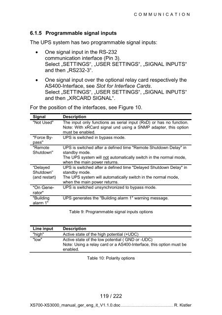
K O M M U N I K A T I O N6.1.5 Prog
- Page 47 and 48:
W A R T U N G7. Wartung7.1 Pflege u
- Page 49 and 50:
W A R T U N GACHTUNGBatterien müss
- Page 51 and 52:
W A R T U N G4. Ziehen Sie den Batt
- Page 53 and 54:
W A R T U N G7.4.3 Austausch der in
- Page 55 and 56:
W A R T U N G9. Drücken Sie die St
- Page 57 and 58:
W A R T U N GAbbildung 19: Typische
- Page 59 and 60:
F E H L E R B E H E B U N G8. Fehle
- Page 61 and 62:
F E H L E R B E H E B U N GAlarmsig
- Page 63 and 64:
8.2 Stummschalten des WarnsignalsDr
- Page 65 and 66:
T E C H N I S C H E D A T E N9.1.2
- Page 67 and 68: T E C H N I S C H E D A T E NAlle M
- Page 69 and 70: T E C H N I S C H E D A T E N9.1.6
- Page 71 and 72: T E C H N I S C H E D A T E NAbbild
- Page 73 and 74: 10. GarantieDie ONLINE USV-Systeme
- Page 75 and 76: User ManualONLINE XANTO S series (a
- Page 77 and 78: ContentsUser Manual ...............
- Page 79 and 80: List of figuresFigure 1: XANTO S To
- Page 81 and 82: I N T R O D U C T I O NRack models
- Page 83 and 84: S A F E T Y W A R N I N G SCAUTIONB
- Page 85 and 86: XANTO S 700XANTO S 1000XANTO S 1500
- Page 87 and 88: I N S T A L L A T I O NConnecting t
- Page 89 and 90: I N S T A L L A T I O N1. Installat
- Page 91 and 92: I N S T A L L A T I O NFigure 5: Re
- Page 93 and 94: I N S T A L L A T I O NModels with
- Page 95 and 96: I N S T A L L A T I O N8. Press the
- Page 97 and 98: O P E R A T I O N4.1.1 Changing the
- Page 99 and 100: O P E R A T I O NFrequencyConverter
- Page 101 and 102: O P E R A T I O NNumber of BatteryS
- Page 103 and 104: O P E R A T I O NNOTEDepending on t
- Page 105 and 106: O P E R A T I O N5. Check the displ
- Page 107 and 108: O P E R A T I O N4.5 Setting the po
- Page 109 and 110: O P E R A T I O NEach UPS system ha
- Page 111 and 112: O P E R A T I O N4.8.2 Performing t
- Page 113 and 114: C O M M U N I C A T I O N6. Communi
- Page 115 and 116: C O M M U N I C A T I O N1 See “P
- Page 117: C O M M U N I C A T I O NFor the po
- Page 121 and 122: M A I N T E N A N C E7. Maintenance
- Page 123 and 124: M A I N T E N A N C ECAUTIONBatteri
- Page 125 and 126: M A I N T E N A N C E4. Carefully p
- Page 127 and 128: M A I N T E N A N C E7.4.3 Replacin
- Page 129 and 130: M A I N T E N A N C E9. Press the p
- Page 131 and 132: M A I N T E N A N C EFigure 19: Typ
- Page 133 and 134: T R O U B L E S H O O T I N G8. Tro
- Page 135 and 136: T R O U B L E S H O O T I N GAlarm
- Page 137 and 138: T R O U B L E S H O O T I N G8.2 Mu
- Page 139 and 140: T E C H N I C A L D A T A9.1.2 Dime
- Page 141 and 142: T E C H N I C A L D A T AAll models
- Page 143 and 144: T E C H N I C A L D A T A9.1.6 Comm
- Page 145 and 146: T E C H N I C A L D A T AFigure 24:
- Page 147 and 148: W A R R A N T Y10. WarrantyONLINE U
- Page 149 and 150: Manuale dell'utenteONLINE XANTO Ser
- Page 151 and 152: IndiceManuale dell'utente .........
- Page 153 and 154: Elenco delle figureFigura 1: XANTO
- Page 155 and 156: I N T R O D U Z I O N ESlot per ada
- Page 157 and 158: A V V E R T E N Z E D I S I C U R E
- Page 159 and 160: XANTO S 700XANTO S 1000XANTO S 1500
- Page 161 and 162: M O N T A G G I OCollegamento dei p
- Page 163 and 164: M O N T A G G I O1. Montaggio del k
- Page 165 and 166: M O N T A G G I OFigura 5: Rimozion
- Page 167 and 168: M O N T A G G I OModelli da 2.000 -
- Page 169 and 170:
M O N T A G G I O8. Premere il tast
- Page 171 and 172:
F U N Z I O N A M E N T O4.1.1 Modi
- Page 173 and 174:
F U N Z I O N A M E N T OFrequencyC
- Page 175 and 176:
F U N Z I O N A M E N T OSynchroniz
- Page 177 and 178:
F U N Z I O N A M E N T OAVVERTENZA
- Page 179 and 180:
F U N Z I O N A M E N T O5. Control
- Page 181 and 182:
F U N Z I O N A M E N T O4.5 Impost
- Page 183 and 184:
F U N Z I O N A M E N T O4.7 Config
- Page 185 and 186:
F U N Z I O N A M E N T O4.8.2 Esec
- Page 187 and 188:
C O M U N I C A Z I O N E6. Comunic
- Page 189 and 190:
C O M U N I C A Z I O N E1 vede Seg
- Page 191 and 192:
C O M U N I C A Z I O N EPer la pos
- Page 193 and 194:
C O M U N I C A Z I O N E6.1.5 Segn
- Page 195 and 196:
M A N U T E N Z I O N E7. Manutenzi
- Page 197 and 198:
M A N U T E N Z I O N EATTENZIONELe
- Page 199 and 200:
M A N U T E N Z I O N E4. Estrarre
- Page 201 and 202:
M A N U T E N Z I O N E7.4.3 Sostit
- Page 203 and 204:
M A N U T E N Z I O N E9. Premere l
- Page 205 and 206:
M A N U T E N Z I O N EFigura 19: I
- Page 207 and 208:
E L I M I N A Z I O N E D E I G U A
- Page 209 and 210:
E L I M I N A Z I O N E D E I G U A
- Page 211 and 212:
E L I M I N A Z I O N E D E I G U A
- Page 213 and 214:
D A T I T E C N I C I9.1.2 Pesi e d
- Page 215 and 216:
D A T I T E C N I C ITutti i modell
- Page 217 and 218:
D A T I T E C N I C I9.1.6 Opzioni
- Page 219 and 220:
D A T I T E C N I C IFigura 24: XAN
- Page 221 and 222:
G A R A N Z I A10. GaranziaONLINE U