Benutzerhandbuch - Online USV Systeme
Benutzerhandbuch - Online USV Systeme
Benutzerhandbuch - Online USV Systeme
- No tags were found...

Create successful ePaper yourself
Turn your PDF publications into a flip-book with our unique Google optimized e-Paper software.
Inhalt<strong>Benutzerhandbuch</strong> ............................................................................. 11. Einleitung .................................................................................... 62. Sicherheitswarnungen ................................................................ 83. Montage .................................................................................... 103.1 Überprüfung der Lieferung ................................................ 103.2 Auspacken der <strong>USV</strong>-Anlage ............................................. 103.3 Überprüfung des Zubehörs ............................................... 113.4 Installation des Tower-Modells .......................................... 113.4.1 Mechanischer Aufbau ....................................................... 113.4.2 Elektrische Installation ...................................................... 123.5 Installation des Rack-Modells ........................................... 143.5.1 Mechanischer Einbau ........................................................ 143.5.2 Elektrische Installation ...................................................... 163.6 Inbetriebnahme ................................................................. 204. Betrieb ...................................................................................... 224.1 Funktionen auf dem Bedienfeld ........................................ 224.1.1 Ändern der Sprache .......................................................... 234.1.2 Anzeigefunktionen ............................................................. 234.1.3 Anwenderprogrammierung ................................................ 244.2 Betriebsarten ..................................................................... 284.2.1 Normalbetrieb .................................................................... 284.2.2 Batteriebetrieb ................................................................... 284.2.3 Bypassbetrieb .................................................................... 294.2.4 Standbybetrieb .................................................................. 304.3 Starten und Abschalten der <strong>USV</strong>-Anlage .......................... 304.3.1 Starten der <strong>USV</strong>-Anlage .................................................... 304.3.2 Starten der <strong>USV</strong>-Anlage im Batteriebetrieb ...................... 314.3.3 Abschalten der <strong>USV</strong>-Anlage ............................................. 324.4 Betriebsartwechsel der <strong>USV</strong>-Anlage ................................. 324.5 Einstellen der Energiestrategie ......................................... 334.6 Konfigurieren der Bypass-Einstellungen ........................... 334.7 Konfigurieren von Lastsegmenten .................................... 344.8 Konfigurieren der Batterieeinstellungen ............................ 364.8.1 Konfigurieren der <strong>USV</strong>-Anlage für Batteriepakete ............ 364.8.2 Ausführen der automatischen Batterietests ...................... 374.8.3 Konfigurieren des automatischen Neustarts ..................... 373 / 222XS700-XS3000_manual_ger_eng_it_V1.1.0.doc ........................................................... R. Kistler
5. Spezialfunktionen ..................................................................... 385.1 Frequenzumrichterbetrieb ................................................. 386. Kommunikation ......................................................................... 396.1 Kommunikationsoptionen .................................................. 396.1.1 RS-232- und USB-Kommunikationsschnittstelle ............... 406.1.2 Slot für Schnittstellenkarten .............................................. 416.1.3 Notaus-Funktion (REPO) .................................................. 426.1.4 Programmierbare Ausgangskontakte ............................... 446.1.5 Programmierbare Signaleingänge .................................... 456.2 DataWatch Software ......................................................... 467. Wartung .................................................................................... 477.1 Pflege und Wartung von <strong>USV</strong>-Anlagen / Batterien ........... 477.2 Lagerung von <strong>USV</strong>-Anlagen / Batterien ............................ 477.3 Zeitpunkt für das Austauschen der Batterien .................... 487.4 Batterien wechseln ............................................................ 487.4.1 Austausch der internen Batterien des Tower-Modells ...... 497.4.2 Austausch des Batteriepaketes des Tower-Modells ......... 527.4.3 Austausch der internen Batterien des Rack-Modells ........ 537.4.4 Austausch des Batteriepaketes vom Rack-Modell ............ 557.5 Testen der neuen Batterien ............................................... 577.6 Entsorgen der Altbatterien oder der <strong>USV</strong>-Anlage ............. 588. Fehlerbehebung ....................................................................... 598.1 Typische Warn- und Statusmeldungen ............................. 598.2 Stummschalten des Warnsignals ...................................... 638.3 Support .............................................................................. 639. Technische Daten .................................................................... 649.1 Spezifikationen der <strong>USV</strong>-Anlagen ..................................... 649.1.1 Liste der Gerätetypen ........................................................ 649.1.2 Gewichte und Abmessungen (netto) ................................. 659.1.3 Elektrische Ein- und Ausgänge ......................................... 669.1.4 Batterie .............................................................................. 689.1.5 Überbrückungszeit ............................................................ 689.1.6 Kommunikationsoptionen .................................................. 699.1.7 Umwelt und Sicherheit ...................................................... 699.2 Rückansichten der <strong>USV</strong>-Anlagen ...................................... 709.3 CE Bestätigung ................................................................. 7210. Garantie .................................................................................... 734 / 222XS700-XS3000_manual_ger_eng_it_V1.1.0.doc ........................................................... R. Kistler
AbbildungsverzeichnisAbbildung 1: XANTO S Tower und das optionale Batteriepaket .......... 7Abbildung 2: XANTO S Rack und das optionale Batteriepaket ............ 7Abbildung 3: Anschließen der Batteriepakete .................................... 14Abbildung 4: Befestigen der Gehäusefront......................................... 15Abbildung 5: Entfernen der Frontblende von der <strong>USV</strong>-Anlage .......... 17Abbildung 6: Entfernen des Kabelauswurfs vom Batteriepaket ......... 17Abbildung 7: Entfernen der Frontblende vom Batteriepaket .............. 18Abbildung 8: Typische Installation meherer Batteriepakete ............... 19Abbildung 9: XANTO S Bedienfeld (Modell XANTO S 3000R) .......... 22Abbildung 10: Kommunikationsoptionen (Modell XANTO S 3000R) . 39Abbildung 11: RS-232 Kommunikationsschnittstelle (DB-9-Stecker) . 40Abbildung 12: Notaus-Anschluss ........................................................ 43Abbildung 13: Anschlüsse der Standard-Relais-Schnittstelle ............ 44Abbildung 14: Entfernen der Frontblende von der <strong>USV</strong>-Anlage ........ 50Abbildung 15: Austauschen der internen Batterien der <strong>USV</strong>-Anlage . 50Abbildung 16: Entfernen der Frontblende von der <strong>USV</strong>-Anlage ........ 53Abbildung 17: Austauschen der internen Batterien der <strong>USV</strong>-Anlage . 54Abbildung 18: Entfernen der Frontblende vom Batteriepaket ............ 55Abbildung 19: Typische Installation meherer Batteriepakete ............. 57Abbildung 20: XANTO S 700 .............................................................. 70Abbildung 21: XANTO S 1000 und 1500 ............................................ 70Abbildung 22: XANTO S 2000 ............................................................ 70Abbildung 23: XANTO S 3000 ............................................................ 70Abbildung 24: XANTO S 700R, 1000R und 1500R ............................ 71Abbildung 25: XANTO S 2000R ......................................................... 71Abbildung 26: XANTO S 3000R ......................................................... 715 / 222XS700-XS3000_manual_ger_eng_it_V1.1.0.doc ........................................................... R. Kistler
E I N L E I T U N G1. EinleitungDie ONLINE <strong>USV</strong>-<strong>Systeme</strong> AG (ONLINE) gehört zu den führendenHerstellern von unterbrechungsfreien Stromversorgungen (<strong>USV</strong>).Seit 1988 beschäftigt sich das deutsche Unternehmen mit Entwicklung,Fertigung, Vertrieb und Support von <strong>USV</strong>-<strong>Systeme</strong>n. Nach verkauftenStückzahlen sind die Produkte der ONLINE die deutscheNummer eins im <strong>USV</strong>-Markt und wegen ihrer hohen Qualität und desexzellenten Supports international anerkannt.Die XANTO S Serie ist eine <strong>USV</strong>-Anlage, die erstklassigen Stromversorgungsschutzfür Ihre empfindlichen elektronischen Anlagenbietet. Sie schützt vor den häufigsten Versorgungsproblemen wiez.B. Netzausfall, Spannungseinbrüchen, Über- und Unterspannung,Spannungsstößen, Störsignalen, Schalt- und Spannungsspitzen,Frequenzabweichungen und harmonischen Verzerrungen.Das Versorgungsnetz fällt häufig dann aus, wenn man es am wenigstenerwartet, und die Qualität der Stromversorgung kann oft erheblichenSchwankungen unterliegen. Netzprobleme können dazuführen, dass kritische Daten zerstört werden, ungesicherte Datenverloren gehen und Hardware beschädigt wird, was zu teuren Reparaturenund Ausfallstunden führt.Mit der XANTO S werden Ihre Anlagen vor Stromversorgungsproblemensicher geschützt, und die Funktionsfähigkeit der Geräte bleibterhalten. Neben erstklassiger Performance und Zuverlässigkeit bietetdie XANTO S die folgenden einzigartigen Vorzüge:Echte Doppelwandlertechnik (VFI-SS-111) mit hoher Leistungsdichte,Generatorkompatibilität sowie Unabhängigkeitvon der NetzfrequenzPerfekte Sinus-AusgangsspannungFrequenzumrichterbetriebZwei unterschiedlich konfigurierbare LastsegmenteAutomatischer Bypass bei Überlast, z. B. beim Einschaltengroßer LastenSkalierbare Überbrückungszeit mit zusätzlichen BatteriepaketenIntelligentes Batteriemanagement (IBM+), für optimierte Ladungund maximale ÜberbrückungszeitHot-Swap Batterie6 / 222XS700-XS3000_manual_ger_eng_it_V1.1.0.doc ........................................................... R. Kistler
ACHTUNGBatterien können das Risiko eines elektrischen Schlags bergenoder durch hohen Kurzschlussstrom in Brand geraten.Bitte treffen Sie die erforderlichen Vorsichtsmaßnahmen. DieWartung muss von qualifiziertem Personal durchgeführt werden,das im Umgang mit Batterien geübt ist und über guteKenntnisse der erforderlichen Vorsichtsmaßnahmen verfügt(siehe Wartung). Halten Sie nicht autorisiertes Personal vonBatterien fernDie Batterien müssen ordnungsgemäß entsorgt werden.Hierbei sind die örtlichen Bestimmungen zu beachtenBatterien dürfen nicht verbrannt werden. Es besteht Explosionsgefahr9 / 222XS700-XS3000_manual_ger_eng_it_V1.1.0.doc ........................................................... R. Kistler
M O N T A G E3. Montage3.1 Überprüfung der LieferungBewahren Sie die Transportkartons und das Verpackungsmaterialfür die Spedition oder die Verkaufsstelle auf. Falls Anlagenteile währenddes Transports beschädigt wurden, reichen Sie innerhalb von24 Stunden eine Transportschaden-Reklamation bei Ihrem Lieferantenein. Wenn Sie eine Beschädigung erst nach der Annahme desGerätes entdecken, reklamieren Sie diese bitte als verdecktenSchaden.3.2 Auspacken der <strong>USV</strong>-AnlageACHTUNGFalls die <strong>USV</strong>-Anlage bei niedriger Umgebungstemperaturausgepackt wird, kann es zu Kondensatbildung innerhalbund außerhalb des Gehäuses kommen. Installieren Sie die<strong>USV</strong>-Anlage nur, wenn Innen- und Außenseite vollständigtrocken sind (Gefahr eines elektrischen Schlages)Die <strong>USV</strong>-Anlage hat ein hohes Gewicht (siehe TechnischeDaten). Vorsicht beim Auspacken und Transportieren der<strong>USV</strong>HINWEISBewegen und öffnen Sie die verpackte <strong>USV</strong>-Anlage vorsichtig.Lassen Sie die Komponenten in der Verpackung, bis dieseinstalliert werden.Zum Auspacken des Gehäuses und des Zubehörs:1. Öffnen Sie den äußeren Karton und nehmen Sie die mit der<strong>USV</strong>-Anlage verpackten Zubehörteile heraus.2. Heben Sie die <strong>USV</strong>-Anlage vorsichtig aus dem äußeren Karton.3. Platzieren Sie die <strong>USV</strong>-Anlage an einer geschützten, ausreichendbelüfteten Stelle, die von Feuchtigkeit, brennbaren Gasenund Korrosion frei ist.10 / 222XS700-XS3000_manual_ger_eng_it_V1.1.0.doc ........................................................... R. Kistler
XANTO S 700XANTO S 1000XANTO S 1500XANTO S 2000XANTO S 3000Batteriepaket XANTO S 1000Batteriepaket XANTO S 1500Batteriepaket XANTO S 2000 / 3000XANTO S 700RXANTO S 1000RXANTO S 1500RXANTO S 2000RXANTO S 3000RBatteriepaket XANTO S 1000RBatteriepaket XANTO S 1500RBatteriepaket XANTO S 2000R / 3000RM O N T A G E3.3 Überprüfung des ZubehörsDer Lieferumfang ist folgender Tabelle zu entnehmen:Beschreibung19"-Montagewinkel(links und rechts)RS-232 Schnittstellenkabel10A Kaltgeräteverlängerung2 2 2 2 2 2 2 21 1 1 1 1 1 1 1 1 12 3 3 4 4 2 3 3 4 416A Netzanschlusskabel 1 1Batteriekabel 1 1 1Software DataWatch 1 1 1 1 1 1 1 1 1 1Bedienungsanleitung 1 1 1 1 1 1 1 1 1 1Tabelle 1: Lieferumfang3.4 Installation des Tower-Modells3.4.1 Mechanischer AufbauDie <strong>USV</strong>-Anlage / das Batteriepaket wird vollständig zusammengebautund anschlussfertig geliefert.ACHTUNGDas Gehäuse hat ein hohes Gewicht (siehe TechnischeDaten). Zum Herausnehmen aus dem Karton werden mindestenszwei Personen benötigt.11 / 222XS700-XS3000_manual_ger_eng_it_V1.1.0.doc ........................................................... R. Kistler
M O N T A G E1. Stellen Sie die <strong>USV</strong>-Anlage auf eine ebene, stabile Oberflächean ihren endgültigen Platz.2. Wenn Sie zusätzliche Batteriepakete installieren, stellen Siediese neben die <strong>USV</strong>-Anlage an ihre endgültigen Plätze.3. Fahren Sie mit dem folgenden Abschnitt Elektrische Installationfort.3.4.2 Elektrische InstallationInstallation der <strong>USV</strong>-AnlageHINWEISNehmen Sie keine unbefugten Veränderungen an der <strong>USV</strong>-Anlage vor, da andernfalls die Anlage beschädigt werdenkann und der Garantieanspruch verloren gehtVerbinden Sie das Anschlusskabel der <strong>USV</strong>-Anlage nicht mitdem Versorgungsnetz, bevor die Installation vollständig abgeschlossenist1. Wenn Sie die DataWatch Software installieren, verbinden SieIhren Computer mit einer der Schnittstellen. Verwenden Siefür die Schnittstellen ein geeignetes Kabel (RS-232 Kabel istim Lieferumfang enthalten).2. Falls ein Not-Aus-Schalter vorgeschrieben ist, finden Sie Hinweisezur Installation im Abschnitt Fernausschalter für Notfälle(Remote Emergency Power-Off, REPO).3. Falls Batteriepakete installiert werden sollen, fahren Sie bittemit dem folgenden Abschnitt Anschließen der Batteriepaketefort, andernfalls blättern Sie weiter zum Abschnitt Hinweise zurInbetriebnahme.12 / 222XS700-XS3000_manual_ger_eng_it_V1.1.0.doc ........................................................... R. Kistler
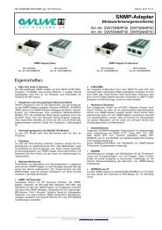
M O N T A G EAnschließen der Batteriepakete1. Entfernen Sie die Kabelklemme an der Rückseite der <strong>USV</strong>-Anlage, die den Batterieanschluss abdeckt. Bewahren SieKlemme und Schrauben auf (siehe Abbildung 3).2. Installation eines einzelnen Batteriepaketes: Entfernen Siedie Kabelklemme, die den rechten (bei Modellen mit 1000 –1500VA) oder den oberen (bei Modellen mit 2000 – 3000VA)Batterieanschluss abdeckt. Bewahren Sie Klemme undSchrauben auf.3. Installation mehrerer Batteriepakete: Entfernen Sie bei allenBatteriepaketen, außer bei dem zuletzt installierten Batteriepaket,die Kabelklemmen beider Batterieanschlüsse. Beimletzten Batteriepaket bleibt der zweite Batterieanschluss abgedeckt(siehe Abbildung 3).Bewahren Sie alle Klemmen und Schrauben auf.ACHTUNGEin kleiner Lichtbogen kann auftreten, wenn das Batteriepaketan die <strong>USV</strong>-Anlage angeschlossen wird. Das ist normalund kann nicht zur Gefährdung von Personen führen. FührenSie das Kabel des Batteriepaketes schnell und kräftig in dieBatterie-Steckverbindung der <strong>USV</strong>-Anlage ein.4. Verbinden Sie alle Steckverbindungen zwischen den Batteriepaketenund der <strong>USV</strong>-Anlage (siehe Abbildung 3). Bis zuvier Batteriepakete können an die <strong>USV</strong>-Anlage angeschlossenwerden.5. Montieren Sie alle vorher entfernten Kabelklemmen um 90Grad verdreht unterhalb der Stecker (siehe Abbildung 3).6. Vergewissern Sie sich, dass alle Steckverbindungen fest verbundensind und alle Kabel mit Zugentlastung sowie ausreichendgroßen Biegeradien versehen sind.7. Fahren Sie mit dem Abschnitt Hinweise zur Inbetriebnahmefort.13 / 222XS700-XS3000_manual_ger_eng_it_V1.1.0.doc ........................................................... R. Kistler
M O N T A G EAbbildung 3: Anschließen der Batteriepakete3.5 Installation des Rack-Modells3.5.1 Mechanischer EinbauDie <strong>USV</strong>-Anlage / das Batteriepaket wird vollständig zusammengebautund anschlussfertig geliefert.Für das Rack-Modell werden optionale Gleitschienen (Art.-Nr. Rack-Kit) angeboten. Die Gleitschienen sind passend für 48 cm (19 Zoll)Racks mit einer Bautiefe von 61 bis 76 cm (24 bis 30 Zoll).HINWEISPro <strong>USV</strong>-Anlage und pro Batteriepaket ist ein Rack-Kit notwendig.1. Montage des Rack-Kits (siehe separate Montageanleitung).14 / 222XS700-XS3000_manual_ger_eng_it_V1.1.0.doc ........................................................... R. Kistler
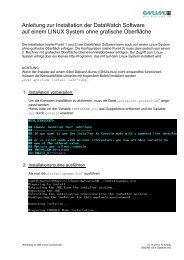
M O N T A G E2. Stellen Sie die <strong>USV</strong>-Anlage auf eine ebene, stabile Oberfläche.Die Vorderseite des Gehäuses ist zu Ihnen gerichtet.3. Richten Sie die Montagewinkel (L = Links und R = Rechts) mitden Schraubenbohrungen auf jeder Seite der <strong>USV</strong>-Anlage ausund befestigen Sie diese mit den beigefügten M4 x 8 Flachkopfschrauben.HINWEISEs befinden sich zwei Sätze von jeweils vier Montagebohrungenauf jeder Seite der <strong>USV</strong>:Ein Satz ist für die vordere, einer für die mittlere Positionvorgesehen. Wählen Sie die Position nach Ihrem Konfigurationsbedarf.4. Wenn Sie zusätzliche <strong>USV</strong>-Anlagen oder Batteriepakete installieren,wiederholen Sie die Schritte 2 und 3.5. Schieben Sie die <strong>USV</strong>-Anlagen und die Batteriepakete in dasRack.6. Befestigen Sie die Front der <strong>USV</strong>-Anlage bzw. des Batteriepaketesam Rack. Verwenden Sie hierfür auf beiden Seiten zweiM6 x 16 Flachkopfschrauben und zwei M6 Käfigmuttern (sieheAbbildung 4). Montieren Sie die untere Schraube auf jederSeite durch das untere Loch des Befestigungswinkels und dasuntere Loch der Schiene.Wiederholen Sie den Vorgang für alle weiteren <strong>USV</strong>-Anlagenund Batteriepakete.Abbildung 4: Befestigen der Gehäusefront15 / 222XS700-XS3000_manual_ger_eng_it_V1.1.0.doc ........................................................... R. Kistler
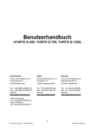
M O N T A G E3.5.2 Elektrische InstallationInstallation der <strong>USV</strong>-AnlageHINWEISNehmen Sie keine unbefugten Veränderungen an der <strong>USV</strong>-Anlage vor, da sonst die Anlage beschädigt werden kannund der Garantieanspruch verloren gehtVerbinden Sie das Anschlusskabel der <strong>USV</strong>-Anlage nicht mitdem Versorgungsnetz, bevor die Installation vollständig abgeschlossenist1. Wenn Sie die DataWatch Software installieren, verbinden SieIhren Computer mit einer der Schnittstellen. Verwenden Siefür die Schnittstellen ein geeignetes Kabel (Ein RS-232 Kabelist im Lieferumfang enthalten).2. Wenn Ihr Rack über Erdungsleiter oder Leiter für den Potenzialausgleichzwischen Metallteilen verfügt, verbinden Sie dasErdungskabel (nicht mitgeliefert) mit der für den Erdungsanschlussvorgesehenen Schraube. Im Abschnitt TechnischeDaten finden Sie Hinweise für die jeweilige Lage der Erdungsschraubefür jedes Modell.3. Falls ein Not-Aus-Schalter vorgeschrieben ist, finden Sie Hinweisezur Installation im Abschnitt Fernausschalter für Notfälle(Remote Emergency Power-Off, REPO).4. Fahren Sie mit dem Abschnitt Hinweise zur Inbetriebnahmefort.Anschließen der Batteriepakete1. Entfernen Sie die Frontblende der <strong>USV</strong>-Anlage (siehe Abbildung5).Um die Blende zu entfernen, lösen und entfernen Sie die beidenSchrauben an der rechten Seite der Blende. Fassen Siedie Blende an zwei Seiten an, schieben Sie sie nach links undentfernen Sie sie vom Gehäuse.16 / 222XS700-XS3000_manual_ger_eng_it_V1.1.0.doc ........................................................... R. Kistler
M O N T A G EHINWEISEin Flachbandkabel verbindet das LCD Anzeige- und Bedienfeldmit der <strong>USV</strong>. Ziehen Sie nicht an dem Kabel und trennenSie die Verbindung nicht.Abbildung 5: Entfernen der Frontblende von der <strong>USV</strong>-Anlage2. Entfernen Sie den Kabelauswurf an der Unterseite der Frontblendeder <strong>USV</strong>-Anlage (siehe Abbildung 6).HINWEISGehen Sie vorsichtig vor, um das LCD Anzeige- und Bedienfeldund das angeschlossene Flachbandkabel nicht zu beschädigen.Abbildung 6: Entfernen des Kabelauswurfs vom Batteriepaket3. Entfernen Sie die Frontblende von jedem einzelnen Batteriepaket(siehe Abbildung 7).Um die Blende zu entfernen, lösen und entfernen Sie die beidenSchrauben an der rechten Seite der Blende. Fassen Siedie Blende an zwei Seiten an, schieben Sie sie nach links undentfernen Sie sie vom Gehäuse.17 / 222XS700-XS3000_manual_ger_eng_it_V1.1.0.doc ........................................................... R. Kistler
M O N T A G EAbbildung 7: Entfernen der Frontblende vom Batteriepaket4. Entfernen Sie bei dem unteren (oder einzigen) Batteriepaketden Kabelauswurf nur an der Oberseite der Frontblende. InAbbildung 7 wird die Lage des oberen Kabelauswurfs dargestellt.5. Falls Sie mehr als ein Batteriepaket installieren, müssen beijedem Batteriepaket jeweils die oberen und unteren Kabelauswürfeentfernt werden. In Abbildung 7 wird die jeweiligeLage der Kabelauswürfe dargestellt.ACHTUTNGEin kleiner Lichtbogen kann auftreten, wenn das Batteriepaketan die <strong>USV</strong>-Anlage angeschlossen wird. Das ist normalund kann nicht zur Gefährdung von Personen führen. FührenSie das Kabel des Batteriepaketes schnell und kräftig in dieBatterie-Steckverbindung der <strong>USV</strong>-Anlage ein.6. Stecken Sie das Kabel des Batteriepaketes in den Batterieanschlussder <strong>USV</strong>-Anlage, wie in Abbildung 8 dargestellt wird.Bis zu vier Batteriepakete können an die <strong>USV</strong>-Anlage angeschlossenwerden.Modelle bis 1500VA: Lösen Sie die Steckverbindung für dasBatteriepaket an der <strong>USV</strong>-Anlage und verbinden die Steckverbindungmit dem Anschluss am Batteriepaket. Drücken Sie diebeiden Teile kräftig zusammen, um eine gute Verbindung sicherzustellen.18 / 222XS700-XS3000_manual_ger_eng_it_V1.1.0.doc ........................................................... R. Kistler
M O N T A G EModelle mit 2000 – 3000VA: Verbinden Sie rot mit rot,schwarz mit schwarz und grün mit grün. Drücken Sie die beidenTeile kräftig zusammen, um eine gute Verbindung herzustellen.Alle Modelle: Um ein zweites Batteriepaket anzuschließen,lösen Sie die Steckverbindung am ersten Batteriepaket. ZiehenSie die Verbindung vorsichtig zum Anschluss des zweitenBatteriepaketes. Wiederholen Sie den Vorgang für jedes weitereBatteriepaket.7. Stellen Sie sicher, dass die Verbindungen der Batteriepaketesich nicht lösen. Angemessene Biegeradien und Zugentlastungenfür alle Kabel müssen vorhanden sein.Abbildung 8: Typische Installation meherer Batteriepakete8. Einsetzen der Frontblende des Batteriepaketes:Um die Blende wieder einzusetzen, stellen Sie sicher, dassdie Kabel des Batteriepaketes durch die Kabelauswürfe geführtsind. Schieben Sie anschließend die Blende nach rechts,bis sie in die Halterung an der linken Seite des Gehäuses einrastet.Bringen Sie die beiden Schrauben an der rechten Seiteder Frontblende wieder an.Wiederholen Sie den Vorgang für jedes zusätzliche Batteriepaket.9. Stellen Sie sicher, dass die gesamte Verdrahtung und alleSteckverbindungen der <strong>USV</strong>-Anlage sowie der Batteriepaketehinter der Frontblende liegen und für den Nutzer unzugänglichsind.19 / 222XS700-XS3000_manual_ger_eng_it_V1.1.0.doc ........................................................... R. Kistler
M O N T A G E3.6 InbetriebnahmeHINWEISVergewissern Sie sich, dass die Gesamtnennleistung allerangeschlossenen Geräte die Kapazität der <strong>USV</strong>-Anlage nichtüberschreitet.1. Im Falle der Installation optionaler Batteriepakete stellen Siesicher, dass diese richtig an die <strong>USV</strong>-Anlage angeschlossensind (siehe Anschließen der Batteriepakete/Tower- bzw. Rack-Modell).2. Verbinden Sie die zu schützenden Geräte mit der <strong>USV</strong>-Anlage, ohne die Geräte einzuschalten.3. Achten Sie auf die notwendigen Befestigungen und Zugentlastungender Kabel.4. Stecken Sie das Netzanschlusskabel der <strong>USV</strong>-Anlage in eineSteckdose (bei 3000VA Modell im Lieferumfang).Das LCD-Display an der Frontblende der <strong>USV</strong>-Anlage leuchtetauf und zeigt das ONLINE Logo an.5. Drücken Sie die Taste an der Frontblende der <strong>USV</strong>-Anlagemindestens eine Sekunde lang. Das Display zeigt den Status„UPS starting“ an.6. Falls das Display der <strong>USV</strong>-Anlage aktive Warnmeldungen anzeigt,beheben Sie die Probleme, bevor Sie mit der Inbetriebnahmefortfahren (siehe Fehlerbehebung).Falls die Anzeige aufleuchtet, fahren Sie erst fort, nachdemSie alle Warnmeldungen beseitigt haben. Überprüfen Sieden Status der <strong>USV</strong>-Anlage auf dem Display und achten Sieauf alle Warnmeldungen. Beheben Sie diese und starten Siedie <strong>USV</strong>-Anlage neu, falls erforderlich.7. Vergewissern Sie sich, dass die Anzeige durchgehendleuchtet. Dadurch wird angezeigt, dass die <strong>USV</strong>-Anlage imNormalbetrieb arbeitet und angeschlossene Lasten versorgtwerden.20 / 222XS700-XS3000_manual_ger_eng_it_V1.1.0.doc ........................................................... R. Kistler
8. Drücken Sie die esc Taste bis das Display den Startbetriebanzeigt.Die <strong>USV</strong>-Anlage sollte sich im Modus „Normalbetrieb“ befinden.9. Falls zusätzliche Batteriepakete installiert sind, muss die Anzahlder installierten Batteriepakete in der <strong>USV</strong>-Anlage eingestelltwerden (siehe Betrieb – Konfigurieren der <strong>USV</strong>-Anlagefür Batteriepakete).10. Zum Ändern werksseitiger Voreinstellungen lesen Sie bitteden Abschnitt Anwenderprogrammierung im Kapitel Betrieb.HINWEISONLINE empfiehlt die Einstellung von Datum und UhrzeitBeim ersten Starten wird die Ausgangsfrequenz auf denWert der Eingangsfrequenz gesetzt (die automatische Erkennungist standardmäßig aktiviert).Beim ersten Starten wird die Ausgangsspannung auf 230Vgesetzt (die automatische Erkennung ist standardmäßig deaktiviert).11. Falls ein zusätzlicher Notaus-Schalter installiert wurde, mussdie Notaus-Funktion geprüft werden:Betätigen Sie hierzu den Notaus-Schalter und überprüfen Sieden Statuswechsel auf dem Display der <strong>USV</strong>-Anlage.Deaktivieren Sie den Notaus-Schalter und starten Sie die<strong>USV</strong>-Anlage neu.HINWEISDie internen Batterien lassen sich in weniger als drei Stundenauf 90% ihrer Kapazität aufladen. ONLINE empfiehlt, dieBatterien nach der Installation oder nach längerer Lagerung48 Stunden lang aufzuladen. Wenn zusätzliche Batteriepaketeinstalliert wurden, lesen Sie die Ladezeiten im AbschnittTechnische Daten nach.21 / 222XS700-XS3000_manual_ger_eng_it_V1.1.0.doc ........................................................... R. Kistler
B E T R I E B4. BetriebDieser Abschnitt enthält Informationen über die Verwendung derXANTO S 700 - 3000VA, wie Nutzung des Bedienfeldes an der Vorderseite,Betriebsarten, Starten und Abschalten der <strong>USV</strong>-Anlage,Wechseln zwischen verschiedenen Betriebsarten, Abrufen des Ereignisprotokolls,Einstellung der Energiestrategie und Konfigurierender Bypass-Einstellungen, Lastsegmente, Batterieeinstellungen undKommunikation.4.1 Funktionen auf dem BedienfeldAbbildung 9: XANTO S Bedienfeld (Modell XANTO S 3000R)Anzeige Status BeschreibungEIN Die <strong>USV</strong>-Anlage läuft im Normalbetrieb.GrünGelbGelbRotBlinktEINBlinktEINEINEine neue Informationsmeldung ist aktiv.Die <strong>USV</strong>-Anlage befindet sich im Batteriebetrieb.Die Batteriespannung liegt unterhalb der Warnmeldungsschwelle.Die <strong>USV</strong>-Anlage befindet sich im Bypassbetrieb.Die <strong>USV</strong>-Anlage funktioniert während des Hocheffizienzbetriebsordnungsgemäß im Bypassbetrieb.Eine Warnmeldung ist aktiv oder ein Fehler liegt vor. (sieheFehlerbehebung).Tabelle 2: Anzeigebeschreibungen22 / 222XS700-XS3000_manual_ger_eng_it_V1.1.0.doc ........................................................... R. Kistler
B E T R I E B4.1.1 Ändern der SpracheDrücken Sie die esc Taste auf der linken Seite und halten Sie dieseetwa drei Sekunden lang gedrückt, um das Sprachmenü auszuwählen.Dieser Vorgang kann von jedem Menü ausgeführt werden.4.1.2 AnzeigefunktionenStandardmäßig oder nach 15-minütiger Inaktivität zeigt das LCD denStartbildschirm an.Das hintergrundbeleuchtete LCD wird nach 15-minütiger Inaktivitätautomatisch abgeschaltet. Drücken Sie eine beliebige Taste, um dieBeleuchtung wieder zu aktiveren.Drücken Sie eine beliebige Taste, um die Menüoptionen zu aktivieren.Mit den beiden Tasten und können Sie durch die Menüstrukturblättern. Mit der Taste können Sie eine Option auswählen.Mit der esc Taste können Sie den Vorgang abbrechen oder zumvorherigen Menü zurückkehren.Hauptmenu Untermenü Anzeigeinformation der Menüfunktion<strong>USV</strong>-StatusHauptstatus (Betriebsart und Last) / Hinweisoder Warnstatus (sofern vorhanden) / Batteriestatus(Status und Ladestand)EreignisaufzeichnungZeigt bis zu 127 Ereignisse und Warnmeldungenan.Messwerte - Last W | VA- Last A | pf- Ausgang V | Hz- Eingang V | Hz- Bypass V | Hz- Ereignisse des Eingangsstroms- Batterie V min.Kontrolle „Auf Bypassbetriebschalten“Schaltet die <strong>USV</strong>-Anlage auf internen Bypassbetriebum. Wenn dieser Befehl aktiv ist,wechselt die Option zu „Auf Normalbetriebschalten.“„StartBatterietest“Startet einen manuellen Batterietest.(siehe Testen der neuen Batterien).„Fehlerstatuslöschen“Löscht eine Warnmeldung „Batterietest fehlgeschlagen.“„Lastsegmente“ Lastsegment 1: EIN | AUSLastsegment 2: EIN | AUSDiese Befehle haben Vorrang vor der Anwender-Programmierungfür Lastsegmente.(siehe Konfigurieren von Lastsegmenten).„Auf Werkseinstellungzurücksetzen“Stellt die werkseitigen Einstellungen wiederher. Neustart der <strong>USV</strong>-Anlage notwendig.23 / 222XS700-XS3000_manual_ger_eng_it_V1.1.0.doc ........................................................... R. Kistler
B E T R I E BHauptmenu Untermenü Anzeigeinformation der MenüfunktionIdentifikation<strong>USV</strong>-Anlagen-Typ / Teilenummer / Seriennummer/ FirmwareEinstellungen „Anwenderprogrammierung“Zu Einzelheiten siehe Tabelle 4.„Serviceprogrammierung“Dieses Menü ist nur für den Kundendienst unddurch ein Kennwort geschützt.Tabelle 3: Hauptmenü4.1.3 AnwenderprogrammierungBeschreibung Verfügbare Einstellung StandardeinstellungSprache wechseln „Englisch“, „Französisch“, „Spanisch“,„Deutsch“, „Russisch“„Englisch“User PasswortAkustische WarnsignaleSignaleingängeRelaisEinstellungenKonfigurationserielleSchnittstelleDatum und ZeiteinstellungAusgangsspannungAusgangsfrequenzMenüs, Status, Hinweise und Warnmeldungenwerden in den gewählten Sprachen angezeigt.<strong>USV</strong>-Fehler, Ereignisprotokoll und Einstellungenwerden in englischer Sprache angezeigt.Empfehlung: auf Deutsch ändern.„Aktiviert“, „Deaktiviert“Im Modus „Aktiviert“, lautet das Kennwort„USER.“Empfehlung: nicht ändern.„Aktiviert“, „Deaktiviert“Empfehlung: nicht ändern.Datum: yyyy/mm/dd, Zeit: hh:mmEmpfehlung: Datum einstellen.Siehe Programmierbare SignaleingängeEmpfehlung: nicht ändern.Siehe Programmierbare AusgangskontakteEmpfehlung: nicht ändern.1200 Baud, 2400 Baud, 9600 BaudHINWEIS: Für die <strong>USV</strong>-Kommunikation muss„2400 Baud“ gewählt werden.Empfehlung: nicht ändern.200V, 208V, 220V, 230V, 240V,“autom. Erkennung“Empfehlung: nicht ändern.50Hz, 60Hz, „autom. Erkennung“Empfehlung: nicht ändern.„Deaktiviert“„Aktiviert“2008/01/0112:002400 Baud230V„autom.Erkennung“24 / 222XS700-XS3000_manual_ger_eng_it_V1.1.0.doc ........................................................... R. Kistler
BETR I E BFrequenzumrichterÜberlast AlarmLevelAuf Bypass schaltenwenn ÜberlastBetriebsartVerzögerungAuto StartAutom. Shutdownim BatteriebetriebStart imBatteriebetrieb„Aktiviert“, „Deaktiviert“Im Modus „Aktiviert“ funktioniert die <strong>USV</strong>-Anlage als Frequenzumrichter. Der Bypassbetriebund alle Bypass-bezogenen Warnmeldungenwerden deaktiviert.Empfehlung: nicht ändern.10%, 20%, 30%, ... 100%Diese Werte betreffen nur die Warnmeldeschwelle,nicht den <strong>USV</strong>-Betrieb wie Betriebsartwechseloder AbschaltungEmpfehlung: nicht ändern.„Sofort“, „Verzögert“Im Modus „Sofort” wechselt das Gerät bei einerLast von >102% die Betriebsart.Im Modus „Verzögert” erfolgt der Wechselgemäß den Technischen Daten.Empfehlung: nicht ändern.„Normal“, „Hocheffizient“Siehe Einstellen der EnergiestrategieEmpfehlung: nicht ändern.„Deaktiviert“, „Keine Verzögerung“,1s, 2s, … 32767sIm Modus „Deaktiviert“ ist der automatischeNeustart nicht erlaubt. (siehe Konfigurierenvon Lastsegmenten)Empfehlung: an Erfordernisse anpassen.„Deaktiviert“, „Keine Verzögerung“,1s, 2s, … 32767sDie Abschaltung wird abgebrochen, wenn derNetzstrom vor Ablauf der Wartezeit wiederzugeführt wird. (siehe Konfigurieren von Lastsegmenten)Empfehlung: an Erfordernisse anpassen.„Aktiviert“, „Deaktiviert“Eine Mindest-Batteriespannung muss vorhandensein, damit die <strong>USV</strong>-Anlage startet.HINWEIS: Bei der Erst-Inbetriebnahme mussdie <strong>USV</strong>-Anlage am Stromnetz angeschlossensein und Eingangsstrom muss vorhandensein.Empfehlung: nicht ändern.„Deaktiviert“100%„Sofort“„Normal“Segment 1„KeineVerzögerung“Segment 2„KeineVerzögerung“Segment 1„Deaktiviert“Segment 2„Deaktiviert“„Aktiviert“25 / 222XS700-XS3000_manual_ger_eng_it_V1.1.0.doc ........................................................... R. Kistler
B E T R I E BEnergiesparbetriebVerzögerungFernabschaltungVerzögerung beiverzögerter AbschaltungVerzögerungWarnmeldung BatteriebetriebAlarm VerkabelungsfehlerUntererSchwellenwertBypass-SpannungObererSchwellenwertBypass-SpannungQualifiziere Bypass„Innerh.Spezifikationen“SynchronisationsfensterUnsynchronisierteTransfers„Deaktiviert“, 50W, 100W, ... 1000WDer Ausgang der <strong>USV</strong>-Anlage wird ausgeschaltet,wenn die <strong>USV</strong>-Anlage im Batteriebetriebläuft und die Ausgangsleistung unterdem gewählten Schwellenwert liegt.Empfehlung: nicht ändern.„Keine Verzögerung“, 1s, 2s, ... 10800sEmpfehlung: nicht ändern.„Keine Verzögerung“, 1s, 2s, ... 10800sNur über Signaleingang aktivEmpfehlung: nicht ändern.0, 1s, 2s, ... 99sEmpfehlung: nicht ändern.„Aktiviert“, „Deaktiviert“Eine aktive Kabelfehler-Warnmeldung (amEingang) verhindert das Starten der <strong>USV</strong>-Anlage bzw. erzwingt den Batteriebetrieb, fallsdie <strong>USV</strong>-Anlage in Betrieb ist. Der Bypassbetriebwird deaktiviert.Sonderfall IT-System (frz. Isolé Terre): Z.B. inKrankenhäusern, Schiffen und Bahn, auf „Deaktiviert“ändern. Sonst startet <strong>USV</strong>-Anlagenicht.Empfehlung: nur bei Sonderfall ändern.-4%, -5% ... -20% der NennspannungSiehe Konfigurieren der Bypass-EinstellungenEmpfehlung: nicht ändern.+4%, +5% ... +20% der NennspannungSiehe Konfigurieren der Bypass-EinstellungenEmpfehlung: nicht ändern.„Niemals“, „Immer bei <strong>USV</strong>-Fehler“, „Immer“,„Innerh. Spezifikationen“Siehe Konfigurieren der Bypass-EinstellungenEmpfehlung: nicht ändern.„Synchronisation deakt.“,± 0,5Hz, ± 1,0Hz, ± 2,0Hz, ± 3,0Hz]Siehe Konfigurieren der Bypass-EinstellungenEmpfehlung: nicht ändern.Aktiviert, DeaktiviertSiehe Konfigurieren der Bypass-EinstellungenEmpfehlung: nicht ändern.„Deaktiviert“„KeineVerzögerung“120s5s„Aktiviert“-15% derNennspannung+10% derNennspannung± 3,0Hz„Deaktiviert“26 / 222XS700-XS3000_manual_ger_eng_it_V1.1.0.doc ........................................................... R. Kistler
B E T R I E BAnzahl derBatterie StringsBatterieLadebetriebTemperaturkompensiertesLadenBatterieladung in% bis NeustartBatterieladungniedrig AlarmAutomatische BatterietestsSiehe Ausführen der automatischen BatterietestsUmgebungstemperaturWarnungPolarität desREPO EingangsAbschaltverzögerungfür Logik0, 1, 2 ... 10Siehe Konfigurieren der BatterieeinstellungenEmpfehlung: an Erfordernisse anpassen.„IBM-Zyklen“, „Konstant“Empfehlung: nicht ändern.„Aktiviert“, „Deaktiviert“Im Modus „Deaktiviert“ werden die Standardspannungendes Aufladegerätes für 25°Cvorausgesetzt.Empfehlung: nicht ändern.„Ungeprüft“, 10, 20, ... 100Wenn ein Prozentsatz gewählt ist, erfolgt derautomatische Neustart (sofern aktiviert), wenndie Batterieladung den gewählten Wert erreicht.Empfehlung: an Erfordernisse anpassen.„Sofort“, 2Min., 3min, 5Min.Empfehlung: an Erfordernisse anpassen.„Aktiviert“, „Deaktiviert“Empfehlung: nicht ändern.„Aktiviert“, „Deaktiviert“Empfehlung: nicht ändern.„Offen“, „Geschlossen“Empfehlung: an Erfordernisse anpassen.0min, 1Min., 2Min., … 120minEmpfehlung: nicht ändern.Tabelle 4: Menü Anwenderprogrammierung1„IBM-Zyklen“„Aktiviert“„Ungeprüft“3min„Aktiviert“„Aktiviert“„Offen“0min27 / 222XS700-XS3000_manual_ger_eng_it_V1.1.0.doc ........................................................... R. Kistler
B E T R I E B4.2 BetriebsartenDer Status der <strong>USV</strong>-Anlage wird auf dem Bedienfeld an der Vorderseiteangezeigt.4.2.1 NormalbetriebIm Normalbetrieb leuchtet die Anzeige ständig und die <strong>USV</strong>-Anlage wird vom Versorgungsnetz gespeist. Die <strong>USV</strong>-Anlage überwachtdie Batterien und lädt diese je nach Bedarf auf. Zudem bietetsie den am Ausgang der <strong>USV</strong>-Anlage angeschlossenen GerätenStromversorgungsschutz.Die <strong>USV</strong>-Anlage kann gelegentlich unbemerkt in den Hochalarm-Betrieb wechseln. Dies geschieht in der Regel, wenn das Versorgungsnetzungünstigen Bedingungen unterliegt. Im Hochalarm-Betrieb deaktiviert die <strong>USV</strong>-Anlage den Batterie-Support-Test, umbei Bedarf maximale Batteriekapazität zu gewährleisten. Die <strong>USV</strong>-Anlage verbleibt 24 Stunden lang im Hochalarm-Betrieb oder bisdieser Betrieb durch einen Befehl der Energiestrategie geändertwird, bevor sie in die vorherige Betriebsart zurückschaltet.Die optionalen Einstellungen für „High Efficiency (Hocheffizienz)“ und„Energiestrategie“ minimieren die Wärmeabgabe an die Rack-Umgebung (siehe Anwenderprogrammierung).4.2.2 BatteriebetriebWenn die <strong>USV</strong>-Anlage während eines Netzausfalls betrieben wird,ertönt das akustische Warnsignal alle fünf Sekunden und die Anzeigeleuchtet durchgehend.Nach Rückkehr des Netzstroms wechselt die <strong>USV</strong>-Anlage in denNormalbetrieb und die Batterien werden wieder aufgeladen.Ist der Batterieladezustand im Batteriebetrieb niedrig, so blinkt dieAnzeige langsam und das akustische Warnsignal ertönt jede Sekunde.Ist die Warnmeldung „Batteriestand niedrig” eingestellt, so leuchtetdie Anzeige außerdem durchgehend. Diese Warnmeldung gibtnur einen ungefähren Wert an und die tatsächliche Zeit bis zum Abschaltenkann erheblich variieren.28 / 222XS700-XS3000_manual_ger_eng_it_V1.1.0.doc ........................................................... R. Kistler
B E T R I E BHINWEISJe nach Last an der <strong>USV</strong>-Anlage und der Anzahl der angeschlossenenBatteriepakete kann die Warnmeldung „Batteriestandniedrig” bereits angezeigt werden, bevor die Batterieneinen Ladestand von 25% erreicht haben (siehe „TabelleÜberbrückungszeit“ unter Technische Daten).Wenn das Versorgungsnetz nach dem Abschalten der <strong>USV</strong>-Anlagezurückkehrt, wird die <strong>USV</strong>-Anlage automatisch neu gestartet.4.2.3 BypassbetriebIm Falle einer Überlastung oder eines internen Fehlers der <strong>USV</strong>-Anlage schaltet diese auf das Versorgungsnetz um. Der Batteriebetriebist nicht verfügbar und die Verbraucher sind nicht geschützt. Allerdingswird der Netzstrom weiterhin passiv von der <strong>USV</strong>-Anlagegefiltert. Die Anzeige leuchtet auf.Die <strong>USV</strong>-Anlage verbleibt mindestens 5 Sekunden lang im Bypassbetrieb(sofern die Qualität der Bypass-Quelle akzeptabelbleibt). Wenn drei Wechsel in den Bypassbetrieb innerhalb von 10Minuten erfolgen, ohne dass diese durch einen manuellen Befehlvom Benutzer eingegeben wurden, wird die <strong>USV</strong>-Anlage 1 Stundelang, oder bis zum Betätigen einer Taste, im Bypassbetrieb verriegelt.Die <strong>USV</strong>-Anlage wechselt unter folgenden Bedingungen in den Bypassbetrieb: Wenn der Benutzer den Bypassbetrieb über das Bedienfeldmanuell aktiviertWenn die <strong>USV</strong>-Anlage einen internen Fehler erkenntWenn die <strong>USV</strong>-Anlage überhitzt istWenn die <strong>USV</strong>-Anlage einen Überlastungszustand aufweistHINWEISDie <strong>USV</strong>-Anlage schaltet sich nach einer vorgegebenen Verzögerungszeitab, wenn ein Überlastungsfall eintritt (siehe„Tabelle Elektrische Ausgangsleistung“ unter TechnischeDaten).29 / 222XS700-XS3000_manual_ger_eng_it_V1.1.0.doc ........................................................... R. Kistler
B E T R I E B4.2.4 StandbybetriebWenn die <strong>USV</strong>-Anlage ausgeschaltet ist, der Stecker aber in derSteckdose bleibt, läuft die <strong>USV</strong>-Anlage noch immer im Standby-Betrieb. Die Anzeige ist ausgeschaltet, was darauf hinweist, dassfür die angeschlossene Last kein Strom verfügbar ist. Die Batteriewird bei Bedarf geladen, und der Kommunikationsslot wird mit Stromversorgt.Falls das Netz ausfällt und die Ausgangsleistung aufgrund leererBatterien oder eines internen Fehlers der <strong>USV</strong>-Anlage abgeschaltetwird, wechselt die <strong>USV</strong>-Anlage mit einem Warnsignal in den Standby-Betrieb.Sie versorgt den Kommunikationsslot noch bis zu 1,5Stunden lang (einstellungsabhängig) bzw. bis die Batteriespannungunter 1,75 Volt je Zelle sinkt. Es gilt die jeweils zuerst auftretendeBedingung.Falls das Netz ausfällt, während sich die <strong>USV</strong>-Anlage im Standby-Betrieb befindet, schaltet sich die Stromversorgung der Steuerungnach etwa 10 Sekunden aus.Falls die <strong>USV</strong>-Anlage auf Befehle wartet und der Strom ausfällt,schalten sich das Gerät und die Stromversorgung der Steuerungnach etwa 30 Sekunden aus.4.3 Starten und Abschalten der <strong>USV</strong>-Anlage4.3.1 Starten der <strong>USV</strong>-Anlage1. Überprüfen Sie, ob das Netzanschlusskabel der <strong>USV</strong>-Anlageeingesteckt ist.2. Falls noch nicht geschehen, schalten Sie das Versorgungsnetzfür den Stromkreis ein an den die <strong>USV</strong>-Anlage angeschlossenist.Das Display an der Vorderseite der <strong>USV</strong>-Anlage leuchtet aufund zeigt den Status „<strong>USV</strong> wird initialisiert ...“ an.3. Vergewissern Sie sich, dass die <strong>USV</strong>-Anlage in den Standbybetrieb(„<strong>USV</strong> auf Standby“) wechselt.4. Drücken Sie die Taste an der <strong>USV</strong>-Anlage mindestens eineSekunde lang. Die Statusanzeige auf dem Display wechselt zu„<strong>USV</strong> startet“.30 / 222XS700-XS3000_manual_ger_eng_it_V1.1.0.doc ........................................................... R. Kistler
B E T R I E B5. Überprüfen Sie das Display auf aktive Warnmeldungen oderHinweise. Beheben Sie etwaige aktive Warnmeldungen, bevorSie fortfahren (siehe Fehlerbehebung).Falls die Anzeige aufleuchtet, fahren Sie erst fort, nachdemSie alle Warnmeldungen behoben haben. Prüfen Sie den Statusder <strong>USV</strong>-Anlage anhand der Anzeigen und achten Sie aufetwaige aktive Warnmeldungen. Beheben Sie die Warnmeldungenund starten Sie die <strong>USV</strong>-Anlage neu, falls nötig.6. Vergewissern Sie sich, dass die Anzeige durchgehendleuchtet. Hierdurch wird angezeigt, dass die <strong>USV</strong>-Anlage imNormalbetrieb läuft und dass etwaige Lasten mit Strom versorgtwerden. Die <strong>USV</strong>-Anlage sollte sich im Normalbetriebbefinden.7. Drücken Sie die esc Taste, bis der Startbildschirm angezeigtwird.4.3.2 Starten der <strong>USV</strong>-Anlage im BatteriebetriebHINWEISVor der Verwendung dieser Funktion muss die <strong>USV</strong>-Anlagemindestens einmal vom Netz versorgt und aktiviert wordenseinDas Starten im Batteriebetrieb kann deaktiviert werden (siehe„Starten im Batteriebetrieb“ unter Anwenderprogrammierung)1. Drücken Sie die Taste an der <strong>USV</strong>-Anlage, bis das Displayaufleuchtet und der Status „<strong>USV</strong> startet“ angezeigt wird.Die <strong>USV</strong>-Anlage durchläuft einen Selbsttest vom Standby-Betrieb bis zum Batteriebetrieb. Die Anzeige leuchtetdurchgehend. Die <strong>USV</strong>-Anlage versorgt die Anlage mit Strom.2. Prüfen Sie das Display der <strong>USV</strong>-Anlage auf aktive Warnmeldungenoder Hinweise auf fehlenden Netzstrom. Beheben Sieetwaige aktive Warnmeldungen, bevor Sie fortfahren (sieheFehlerbehebung). Der Hinweis „<strong>USV</strong> im Batteriebetrieb“ kannin diesem Fall ignoriert werden.31 / 222XS700-XS3000_manual_ger_eng_it_V1.1.0.doc ........................................................... R. Kistler
B E T R I E BPrüfen Sie den Status der <strong>USV</strong>-Anlage anhand der Anzeigenim Display und achten Sie auf etwaige aktive Warnmeldungen.Beheben Sie die Warnmeldungen und starten Sie das Gerätneu, falls nötig.3. Drücken Sie die esc Taste, bis der Startbildschirm angezeigtwird.4.3.3 Abschalten der <strong>USV</strong>-Anlage1. Drücken Sie die Taste an der <strong>USV</strong>-Anlage drei Sekundenlang.Die <strong>USV</strong>-Anlage beginnt, ein akustisches Signal auszugebenund zeigt den Status „<strong>USV</strong> vor Abschaltung“ an. Die <strong>USV</strong>-Anlage wechselt dann in den Standby-Betrieb und das Displayschaltet sich aus.HINWEISWird die Taste nach weniger als drei Sekunden losgelassen,so kehrt die <strong>USV</strong>-Anlage wieder zu ihrer vorherigen Betriebsartzurück.2. Schalten Sie das Versorgungsnetz für den Stromkreis aus, anden die <strong>USV</strong>-Anlage angeschlossen ist.4.4 Betriebsartwechsel der <strong>USV</strong>-AnlageVom Normal- zum Bypassbetrieb: Drücken Sie eine beliebige Taste,um die Menüoptionen zu aktivieren. Wählen Sie „KONTROLLE“und „AUF BYPASSBETRIEB SCHALTEN“ aus.Vom Bypass- zum Normalbetrieb: Drücken Sie eine beliebige Taste,um die Menüoptionen zu aktivieren. Wählen Sie „KONTROLLE“und „AUF NORMALBETRIEB SCHALTEN“ aus.32 / 222XS700-XS3000_manual_ger_eng_it_V1.1.0.doc ........................................................... R. Kistler
B E T R I E B4.5 Einstellen der EnergiestrategieIn der Einstellung „Hocheffizienz“ läuft die <strong>USV</strong>-Anlage normalerweiseim Bypassbetrieb, wechselt bei Ausfall des Netzes in wenigerals 10ms zum Inverter und wechselt 1 Minute nach Rückkehr desNetzstroms wieder in den Bypassbetrieb. Die Anzeige leuchtetauf, wenn die <strong>USV</strong>-Anlage in den Bypassbetrieb wechselt.HINWEISDer Hocheffizienzbetrieb ist nach einer Minute stabilerStromversorgung verfügbar.1. Drücken Sie eine beliebige Taste, um die Menüoptionen zuaktivieren. Wählen Sie „EINSTELLUNGEN“, „ANWENDER-PROGRAMMIERUNG“ und anschließend „BETRIEBSART“aus.2. Wählen Sie „HOCHEFFIZIENZBETRIEB“ für HocheffizienzBetrieb oder „NORMAL“, und bestätigen Sie mit der Taste.4.6 Konfigurieren der Bypass-EinstellungenAuf Bypass schalten wenn Überlast: Standardmäßig wird einWechsel in den Bypassbetrieb erzwungen, wenn eine Überlastungauftritt. Sie können die Einstellung für einen verzögerten Wechselkonfigurieren. Die Wartezeit richtet sich dabei nach dem Grad derÜberlastung (siehe „Tabelle 15: Elektrische Ein- und Ausgangsleistung“unter Technische Daten).Unterer Schwellenwert Bypass-Spannung: Standardmäßig ist einWechsel in den Bypassbetrieb deaktiviert, wenn die gemessene Bypass-Spannungminus 15% unter der Nenn-Ausgangsspannungliegt. Sie können die Einstellung für einen anderen Prozentsatz derNennspannung festlegen. Diese Einstellung kann durch die Einstellung„Qualifiziere Bypass” außer Kraft gesetzt werden.Oberer Schwellenwert Bypass-Spannung. Standardmäßig ist einWechsel in den Bypassbetrieb deaktiviert, wenn die gemessene Bypass-Spannungplus 10% über der Nenn-Ausgangsspannung liegt.Sie können die Einstellung für einen anderen Prozentsatz der Nennspannungfestlegen. Diese Einstellung kann durch die Einstellung„Qualifiziere Bypass” außer Kraft gesetzt werden.33 / 222XS700-XS3000_manual_ger_eng_it_V1.1.0.doc ........................................................... R. Kistler
B E T R I E BQualifiziere Bypass. Standardmäßig wird ein Wechsel in den Bypassbetriebnur dann zugelassen, wenn sich der Bypass innerhalbder folgenden Spezifikationen befindet:Die Bypass-Spannung liegt zwischen dem eingestellten „UnterenSchwellenwert für Bypass-Spannung“ und dem „OberenSchwellenwert für Bypass-Spannung“Die Bypass-Frequenz liegt innerhalb der Nennfrequenz mit einerAbweichung von maximal ±5HzDer Inverter ist mit dem Bypass synchronisiert, wenn die Einstellung„Unsynchronisierte Transfers“ deaktiviert istSie können den Bypass verbieten („Niemals“) oder immer zulassen(„Immer“), ohne dass die Spezifikationen überprüft werden. Im Modus„Immer bei <strong>USV</strong>-Fehler“ erfolgt bei einem Fehler der <strong>USV</strong>-Anlage stets ein Wechsel in den Bypassbetrieb. Andernfalls wird dieder Standardeinstellung entsprechende Betriebsart gewählt.Synchronisierungsfenster: Die <strong>USV</strong>-Anlage versucht, sich mit demBypass zu synchronisieren, wenn die Bypass-Frequenz unterhalbdes für die Einstellung „Synchronisierungsfenster“ festgelegten Wertesliegt. Liegt die Bypass-Frequenz oberhalb des eingestellten Wertes,wechselt die <strong>USV</strong>-Anlage zur Normalfrequenz. Im Bypassbetriebbeträgt das Synchronisierungsfenster ±5Hz. Ist die Synchronisierungdeaktiviert („Synchronisation deakt.“), so synchronisiert sichdie <strong>USV</strong>-Anlage nur im Bypassbetrieb.Unsynchronisierte Transfers. Die Standardeinstellung erlaubt einenunsynchronisierten Wechsel zum Bypassbetrieb. Sie können dieEinstellung so konfigurieren, dass derartige Wechsel nicht erlaubtsind. Diese Einstellung kann durch die Einstellung „Qualifiziere Bypass“außer Kraft gesetzt werden.4.7 Konfigurieren von LastsegmentenLastsegmente sind Gruppen von Ausgangssteckdosen der <strong>USV</strong>-Anlage, die von der DataWatch-Software oder über das Display gesteuertwerden können und ein physikalisches Abschalten und Startender Last ermöglichen. Beispielsweise können Sie während einesNetzausfalls wichtige Geräte der Anlage in Betrieb lassen, währendandere ausgeschaltet werden. Mit dieser Funktion können Sie Batteriestromsparen.34 / 222XS700-XS3000_manual_ger_eng_it_V1.1.0.doc ........................................................... R. Kistler
B E T R I E BJede <strong>USV</strong>-Anlage verfügt über zwei konfigurierbare Lastsegmente:Lastsegment 1: Die oberen oder linken SteckdosenLastsegment 2: Die unteren oder rechten Steckdosen(siehe „Rückseiten der <strong>USV</strong>-Anlagen“ unter Technische Daten).So steuern Sie die Lastsegmente über das Display:1. Drücken Sie eine beliebige Taste, um die Menüoptionen zuaktivieren. Wählen Sie „KONTROLLE“ und „LASTSEGMEN-TE“ aus.2. Setzen Sie das gewünschte Lastsegment mit den Tastenbzw. auf „AN“ oder „AUS“ und wählen Sie die Taste, umdie Auswahl zu bestätigen.3. Stellen Sie das andere Lastsegment ein, sofern benötigt.So stellen Sie die Wartezeiten für Neustart und Abschaltung der einzelnenLastsegmente ein:1. Drücken Sie auf eine beliebige Taste, um die Menüoptionenzu aktivieren. Wählen Sie „EINSTELLUNGEN“, „ANWENDERPROGRAMMIERUNG“ und anschließend „VERZÖGERUNGAUTO START“ aus.2. Stellen Sie die Wartezeit für den Neustart eines Lastsegmentsein, und bestätigen Sie die Einstellung mit der Taste.3. Stellen Sie das andere Lastsegment ein, sofern benötigt.4. Wählen Sie „AUTOM. SHUTDOWN IM BATTERIEBETRIEB“.5. Stellen Sie die Wartezeit für die Abschaltung eines Lastsegmentsein, und bestätigen Sie die Einstellung mit der Taste.6. Stellen Sie das andere Lastsegment ein, sofern notwendig.35 / 222XS700-XS3000_manual_ger_eng_it_V1.1.0.doc ........................................................... R. Kistler
B E T R I E B4.8 Konfigurieren der Batterieeinstellungen4.8.1 Konfigurieren der <strong>USV</strong>-Anlage für BatteriepaketeKonfigurieren Sie die <strong>USV</strong>-Anlage für die richtige Anzahl Batteriepakete,um eine maximale Batterielaufzeit zu gewährleisten:1. Drücken Sie eine beliebige Taste am Front-Display, um dieMenüoptionen zu aktivieren, und wählen Sie „EINSTEL-LUNGEN“, „ANWENDER-PROGRAMMIERUNG“ und„ANZAHL DER BATTERIE STRINGS“.2. Wählen Sie die Anzahl der Batteriereihen je nach Ihrer <strong>USV</strong>-Konfiguration mithilfe der oder Taste aus:Anzahl der Batterie StringsAlle <strong>USV</strong>-Anlagen und Batteriepakte0 Nur <strong>USV</strong>-Anlage (keine internen Batterien)1 (Standard) Nur <strong>USV</strong>-Anlage (interne Batterien)3 <strong>USV</strong>-Anlage + 1 Batteriepaket5 <strong>USV</strong>-Anlage + 2 Batteriepakete7 <strong>USV</strong>-Anlage + 3 Batteriepakete9 <strong>USV</strong>-Anlage + 4 BatteriepaketeTabelle 5: Anzahl der BatteriereihenHINWEISFalls 0 gewählt wurde, sind keine internen Batterien und keinezusätzlichen Batteriepakete angeschlossen und alleWarnhinweise bezüglich der Batterien werden deaktiviertDie <strong>USV</strong>-Anlage enthält eine Batteriereihe; jedes Batteriepaketenthält zwei Batteriereihen3. Drücken Sie die Taste, um die Einstellung zu speichern.4. Drücken Sie die esc Taste, bis der Startbildschirm angezeigtwird.36 / 222XS700-XS3000_manual_ger_eng_it_V1.1.0.doc ........................................................... R. Kistler
4.8.2 Ausführen der automatischen BatterietestsAutomatische Batterietests werden alle 30 Tage durchgeführt, soferndiese Option aktiviert wurde. Während des Batterietests wechselt die<strong>USV</strong>-Anlage in den Batteriebetrieb und entlädt die Batterien 25 Sekundenlang an der vorhandenen Last.HINWEISDer Hinweis „<strong>USV</strong> im Batteriebetrieb“ und der Warnhinweis„Batteriestand niedrig“ werden während eines Batterietestsnicht aktiviert.Ausführen automatischer Batterietests:Die Einstellung „Automatische Batterietests“ muss aktiviertseinDie <strong>USV</strong>-Anlage muss sich im Normalzustand befinden, undes dürfen keine Warnmeldungen aktiv seinDie Batterien müssen vollständig aufgeladen seinDie Bypass-Spannung muss akzeptabel seinKein manueller Batterietest wurde vorher in demselben AufladezyklusinitiiertDamit der Batterietest bestanden wird, muss die Batteriespannungwährend des Entladens oberhalb des Schwellenwertes bleiben.4.8.3 Konfigurieren des automatischen NeustartsNach Abschaltung der <strong>USV</strong>-Anlage (z.B. durch leere Batterien beiStromausfall) wird diese automatisch neu gestartet, wenn die Stromversorgungwieder hergestellt wird.Sie können einstellen, wie lange die <strong>USV</strong>-Anlage nach der Wiederaufnahmeder Stromversorgung warten soll, bevor die Lastsegmenteneu gestartet werden. Verwenden Sie hierzu die Einstellung „VerzögerungAuto Start”. Sie können den Neustart der <strong>USV</strong>-Anlage auchso konfigurieren, dass sich dieser nach dem Batterieladestand richtet.Verwenden Sie hierzu die Einstellung „Batterieladung in % bisNeustart“.37 / 222XS700-XS3000_manual_ger_eng_it_V1.1.0.doc ........................................................... R. Kistler
S P E Z I A L F U N K T I O N E N5. Spezialfunktionen5.1 FrequenzumrichterbetriebHINWEISIm Frequenzumrichterbetrieb steht keine Bypass Funktionzur Verfügung und alle Bypass-bezogenen Warnmeldungenwerden deaktiviert.Im Frequenzumrichterbetrieb arbeitet die <strong>USV</strong>-Anlage immer mit einerfest definierten Ausgangsfrequenz (50Hz oder 60Hz), egal welcheEingangsfrequenz (40Hz bis 70Hz) anliegt. Eine feste Ausgangsfrequenzist z.B. für empfindliche Verbraucher erforderlich.1. Drücken Sie eine beliebige Taste, um die Menüoptionen zuaktivieren. Wählen Sie „EINSTELLUNGEN“, „ANWENDER-PROGRAMMIERUNG“ und anschließend „FREQUENZUM-RICHTER“ aus.2. Wählen Sie „AKTIVIERT“ und bestätigen Sie mit der Taste.3. Wechseln Sie anschließend zu „AUSGANGSFREQUENZ“.4. Wählen Sie „50Hz“ oder „60Hz“ und bestätigen Sie mit derTaste.Ist das Versorgungsnetz gestört, wechselt die <strong>USV</strong>-Anlage automatischin den Batteriebetrieb (die Frequenz wird beibehalten). Die Lastwird versorgt, solange die Batteriekapazität ausreichend ist. NachRückkehr des Versorgungsnetzes wechselt die <strong>USV</strong>-Anlage wiederin den Frequenzumrichterbetrieb.38 / 222XS700-XS3000_manual_ger_eng_it_V1.1.0.doc ........................................................... R. Kistler
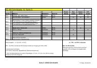
K O M M U N I K A T I O N6. KommunikationAbbildung 10: Kommunikationsoptionen (Modell XANTO S 3000R)6.1 KommunikationsoptionenDie XANTO S hat serielle - (RS-232) und eine USB – Kommunikationsschnittstellesowie einen Slot für optionale Schnittstellenkarten.HINWEISSie können Ausgangskontakte, Signaleingänge und Baudrateder seriellen Schnittstelle mithilfe der Menüs auf dem Bedienfeldkonfigurieren (siehe „Tabelle Anwenderprogrammierung“)Die Datenübertragungsgeschwindigkeit der USB-Schnittstelleist auf 2400 Baud festgelegt39 / 222XS700-XS3000_manual_ger_eng_it_V1.1.0.doc ........................................................... R. Kistler
K O M M U N I K A T I O N6.1.1 RS-232- und USB-KommunikationsschnittstelleUm die Kommunikation zwischen der <strong>USV</strong>-Anlage und einem Computerherzustellen, schließen Sie den Computer mithilfe eines geeignetenDatenkabels (RS-232 - Kabel im Lieferumfang) an eine derKommunikationsschnittstellen der <strong>USV</strong>-Anlage an. In Abbildung 10ist die Position der Kommunikationsschnittstellen dargestellt.HINWEISDie RS-232- und USB-Kommunikationsschnittstelle kannnicht gleichzeitig verwendet werden.Wenn das Verbindungskabel angeschlossen ist, kann die DataWatchSoftware mit der <strong>USV</strong>-Anlage Daten austauschen (siehe „DataWatchSoftware“). Die Software ruft bei der <strong>USV</strong>-Anlage detaillierte Angabenzum Status der Stromversorgungsumgebung ab. Falls eine Notstromversorgungerforderlich wird, löst die Software das Speichernsämtlicher Daten und ein ordnungsgemäßes Abschalten der Anlageaus.Die Belegung der Kabelanschlussstifte für die RS-232-Kommunikationsschnittstelleist in Abbildung 11 dargestellt, die Funktionen derAnschlussstifte entnehmen Sie Tabelle 6.Abbildung 11: RS-232 Kommunikationsschnittstelle (DB-9-Stecker)Pin Funktion Ein-/Ausgang1 Signalausgang (1)(3) Ausgang2 Senden Daten (TxD) Ausgang3 Empfangen Daten (RxD) / Signaleingang (2) Eingang4 Nicht verwendet5 Masse6 Nicht verwendet7 Nicht verwendet8 Signalausgang (1)(3) Ausgang9 +8 - 12VDC Spannung AusgangTabelle 6: Anschlussstiftbelegung der RS-23240 / 222XS700-XS3000_manual_ger_eng_it_V1.1.0.doc ........................................................... R. Kistler
K O M M U N I K A T I O N1 Siehe Programmierbare Ausgangskontakte.2 Siehe Programmierbare Signaleingänge.Signal muss mindestens 5 Sekunden anliegen.3 Wenn der ausgewählte Zustand aktiv ist, wechseln die Ausgabesignaleauf Pin 1 und 8 von „Low” (positive Spannung) zu „High”(negative Spannung). Wenn der Zustand nicht mehr gegeben ist,wechselt das Ausgabesignal wieder zu „Low.”6.1.2 Slot für SchnittstellenkartenDie XANTO S ist mit einem Slot (siehe Abbildung 10) für die folgendenSchnittstellenkarten ausgestattet:Art.-Nr.DW7SNMP30DW5SNMP30PHXNOV-IPHXAS400IBeschreibungSNMP-Adapter BasicDer SNMP-Adapter kommuniziert via TCP/IP mit den angeschlossenenVerbrauchern im Netzwerk.SNMP-Adapter ProfessionalFunktion wie Basic, jedoch mit zusätzlicher Schnittstelle für Temperaturfühlerund Gebäudemanagement.Relais-EinschubkarteMeldung von Batteriebetrieb, Normalbetrieb und Batteriekapazitätniedrig.Signaleingang zur <strong>USV</strong>-Abschaltung.AS400-InterfaceMeldung von <strong>USV</strong>-Alarm, Bypass aktiv, Batteriespannung niedrig,Inverter außer Funktion und Netzausfall.Signaleingang zur <strong>USV</strong>-Abschaltung.Tabelle 7: Schnittstellenkarten41 / 222XS700-XS3000_manual_ger_eng_it_V1.1.0.doc ........................................................... R. Kistler
K O M M U N I K A T I O N6.1.3 Notaus-Funktion (REPO)Die Notaus-Funktion (REPO = Remote Emergency Power-Off) dientzum Herunterfahren der <strong>USV</strong>-Anlage und zum sofortigen Abschaltender angeschlossenen Verbraucher aus der Ferne. Hierzu muss derREPO-Stecker (Rückseite <strong>USV</strong>-Anlage) entfernt und ein externerNotaus-Schalter angeschlossen werden.Kabelquerschnitt Anschlusskabel = 0,32 - 4mm 2 (AWG 22 - 12)Empfohlener Kabelquerschnitt Anschlusskabel = 1,5mm 2 (AWG 18)ACHTUNGDer Notaus-Schalter darf nicht an Schaltkreise angeschlossenwerden, die mit dem Versorgungsnetz verbunden sind.Eine verstärkte Isolierung zum Netz ist erforderlich. DerNotaus-Schalter muss mindestens für 24V und 20mA ausgelegtsein. Es muss ein Öffner verwendet werden. Für denordnungsgemäßen Betrieb muss die Notaus-Funktion mindestens250ms lang aktiv bleibenWenn die die Notaus-Funktion aktiviert wird, muss zusätzlichdie Eingangsspannung der <strong>USV</strong>-Anlage unterbrochen werdenHINWEISLassen Sie den REPO-Stecker im Notaus-Anschluss an der<strong>USV</strong>-Anlage eingesteckt, wenn die Notaus-Funktion nichtbenötigt wirdTesten Sie die Notaus-Funktion immer, bevor eine kritischeLast angeschlossen wird. Hiermit vermeiden Sie eine versehentlicheLastabschaltung42 / 222XS700-XS3000_manual_ger_eng_it_V1.1.0.doc ........................................................... R. Kistler
K O M M U N I K A T I O NZur Lage des REPO-Steckers siehe Abbildung 10.Abbildung 12 zeigt eine Skizze der REPO-Anschlüsse.Abbildung 12: Notaus-AnschlussSie können die REPO-Polarität einstellen. Siehe die Einstellung „Polaritätdes REPO Eingangs“ unter Anwenderprogrammierung.HINWEISJe nach Benutzerkonfiguration müssen die Kontakte geöffnet(Empfehlung) oder geschlossen werden, um den Betrieb der<strong>USV</strong>-Anlage aufrechtzuerhalten. Schließen Sie zum Neustartender <strong>USV</strong>-Anlage die REPO-Anschlusskontakte (bzw. öffnenSie diese erneut) und schalten Sie die <strong>USV</strong>-Anlage vonHand ein. Der maximale Widerstand in dem Schaltkreis beträgt10 Ohm.43 / 222XS700-XS3000_manual_ger_eng_it_V1.1.0.doc ........................................................... R. Kistler
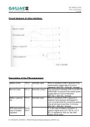
K O M M U N I K A T I O N6.1.4 Programmierbare AusgangskontakteDie <strong>USV</strong>-Anlage hat drei programmierbare Ausgangskontakte:Einen Relais-Ausgangskontakt.Wählen Sie „EINSTELLUNGEN“, „ANWENDER-PROGRAMMIERUNG“, RELAIS EINSTELLUNGEN und anschließend„STANDARD“ aus.Zwei potentialfreie Ausgänge (Optokoppler, max. 5mA)an der RS-232-Kommunikationsschnittstelle (Pin 1 und 8).Wählen Sie „EINSTELLUNGEN“, „ANWENDER-PROGRAMMIERUNG“, RELAIS EINSTELLUNGEN und anschließend„RS232-1“ oder „RS232-8“ aus.Zur Lage der Schnittstellen siehe Abbildung 10.ACHTUNGDer Relais-Ausgangskontakt darf nicht an Schaltkreise angeschlossenwerden, die mit dem Netz verbunden sind. Eineverstärkte Isolierung zum Netz ist erforderlich. Der Relais-Ausgangskontakt hat maximale Nennwerte von 30VAC / 1Aund 60VDC / 2A.Signal„<strong>USV</strong> ok.“„Im Bypass“„Batteriebetrieb“„V Batt.Niedrig“Beschreibung<strong>USV</strong>-Anlage im Normal-, Batterie- oder Bypassbetrieb,keine Warnmeldung aktiv.<strong>USV</strong>-Anlage im Bypassbetrieb.<strong>USV</strong>-Anlage im Batteriebetriebnach definierter Zeit „Verzögerung Warnmeldung Batteriebetrieb”.<strong>USV</strong>-Anlage im Batteriebetrieb und Batteriestand niedrignach definierter Zeit „Batterieladung niedrig Alarm”.Tabelle 8: Optionen programmierbare AusgangskontakteAbbildung 13: Anschluss der Standard-Relais-Schnittstelle44 / 222XS700-XS3000_manual_ger_eng_it_V1.1.0.doc ........................................................... R. Kistler
K O M M U N I K A T I O N6.1.5 Programmierbare SignaleingängeDie <strong>USV</strong>-Anlage hat zwei programmierbare Signaleingänge:Einen Signaleingang an der RS-232-Kommunikationsschnittstelle (Pin 3).Wählen Sie „EINSTELLUNGEN“, „ANWENDER-PROGRAMMIERUNG“, „SIGNAL EINGÄNGE“ und anschließend„RS232-3“ ausEinen Signaleingang über die optionale Relais-Einschubkartebzw. das AS400-Interface, siehe Slot für Schnittstellenkarten.Wählen Sie „EINSTELLUNGEN“, „ANWENDER-PROGRAMMIERUNG“, „SIGNAL EINGÄNGE“ und anschließend„XRCARD KONTAKTE“ ausZur Lage der Schnittstelle siehe Abbildung 10.Signal„Nichtverwendet“„Auf BPzwingen“„Fernabschaltung“„Verz.Abschalt.“„Generatorbetr.“„Gebäudealarm1“BeschreibungDer Eingang dient nur zum Empfangen von Daten (RxD)oder hat keine Funktion.Hinweis: Bei xRCard Kontakte und Betrieb eines SNMP-Adaptersmuss diese Option aktiviert sein.<strong>USV</strong>-Anlage wird in den Bypassbetrieb geschaltet.<strong>USV</strong>-Anlage wird nach definierter Zeit „Verzögerung Fernabschaltung“in den Standbybetrieb geschaltet.Die <strong>USV</strong>-Anlage schaltet nicht automatisch in den Normalbetrieb,bei Rückkehr des Netzstroms.<strong>USV</strong>-Anlage wird nach definierter Zeit „Verzögerung bei verzögerterAbschaltung“ in den Standbybetrieb geschaltet.Die <strong>USV</strong>-Anlage schaltet automatisch in den Normalbetrieb,bei Rückkehr des Netzstroms.<strong>USV</strong>-Anlage wird unsynchronisiert in den Bypassbetrieb geschaltet.<strong>USV</strong>-Anlage erzeugt den Warnhinweis „Gebäudealarm 1.”Tabelle 9: Optionen programmierbare SignaleingängeEingang„high“„low“BeschreibungAktiver Zustand des hohen Potenzials (+UDC)Aktiver Zustand des niedrigen Potenzials (GND oder -UDC)Hinweis: Bei Betrieb einer Relais-Einschubkarte odereines AS400-Interface muss diese Option aktiviert werden.Tabelle 10: Polaritätsoptionen45 / 222XS700-XS3000_manual_ger_eng_it_V1.1.0.doc ........................................................... R. Kistler
K O M M U N I K A T I O N6.2 DataWatch SoftwareZum serienmäßigen Lieferumfang der XANTO S-Serie gehört Data-Watch, die umfassende Softwarelösung zum Shutdown und Managementdes PC- oder Serversystems, sowie zum Monitoring derXANTO S und des Stromversorgungsnetzes.DataWatch arbeitet im Hintergrund und kommuniziert ständig überRS-232-, USB- oder Netzwerk-Protokoll mit der XANTO S. Die bekanntestealler Funktionen: Automatische Datensicherung mit demSchließen laufender Anwendungen und dem geordneten Herunterfahrendes gesamten Systems mittels frei konfigurierbarer Shutdownroutine.Darüber hinaus verfügt DataWatch über ein umfangreichesMessaging-System, zeitgesteuerte Testroutinen sowie eine Ereignisprotokollierung.DataWatch unterstützt alle aktuellen Betriebssysteme.Als Client- / Server-Anwendung arbeitet DataWatch in Netzwerkenund auf lokalen Workstations. Mittels optionalem RCCMD-Agent(Remote Console Command) lassen sich mehrere an einer <strong>USV</strong>-Anlage angeschlossene Server ohne zusätzliche Hardware über dasNetzwerk ansprechen und steuern.46 / 222XS700-XS3000_manual_ger_eng_it_V1.1.0.doc ........................................................... R. Kistler
W A R T U N G7. Wartung7.1 Pflege und Wartung von <strong>USV</strong>-Anlagen / BatterienFür eine lange Lebensdauer der Anlage sollte der Bereich um die<strong>USV</strong>-Anlage sauber und staubfrei sein. Falls es in der Umgebungder Anlage sehr staubig ist, reinigen Sie die Außenflächen der Anlagemit einem Staubsauger.Um eine lange Lebensdauer der Batterien zu erreichen, sollte dieUmgebungstemperatur unter 25°C betragen.HINWEISVergewissern Sie sich vor dem Transport der <strong>USV</strong>-Anlage,dass die <strong>USV</strong>-Anlage vom Versorgungsnetz getrennt undausgeschaltet istDie Batterien in der <strong>USV</strong>-Anlage sind für eine Lebensdauervon drei bis fünf Jahren ausgelegt. Die Lebensdauer einerBatterie variiert je nach Nutzungshäufigkeit und Umgebungstemperatur.Nach Ablauf der zu erwartenden Lebensdauerhaben weiter verwendete Batterien häufig deutlich verringerteLaufzeiten. Tauschen Sie die Batterien spätestens allefünf Jahre aus, damit die Anlage zu jeder Zeit mit optimalerLeistung laufen kann7.2 Lagerung von <strong>USV</strong>-Anlagen / BatterienFalls Sie die <strong>USV</strong>-Anlage über längere Zeit lagern, laden Sie die Batteriealle sechs Monate auf, indem Sie die <strong>USV</strong>-Anlage an das Versorgungsnetzanschließen. Die internen Batterien laden sich in wenigerals drei Stunden auf bis zu 90% ihrer Kapazität auf. ONLINEempfiehlt, die Batterien nach längerer Lagerung (>3 Monate) 48Stunden lang zu laden. Wenn optionale Batteriepakete installiertsind, lesen Sie die Ladezeiten im Abschnitt „Technische Daten“nach.47 / 222XS700-XS3000_manual_ger_eng_it_V1.1.0.doc ........................................................... R. Kistler
W A R T U N G7.3 Zeitpunkt für das Austauschen der BatterienWenn die Anzeige aufleuchtet, das Alarmsignal zu hören ist undder Warnhinweis „Batteriewartung erforderlich“ aufleuchtet, müssendie Batterien ausgetauscht werden. Wenden Sie sich an Ihren Händleroder ONLINE, um neue Batterien zu bestellen.7.4 Batterien wechselnHINWEISEntfernen Sie die Batterien nicht, solange die <strong>USV</strong>-Anlageim Batteriebetrieb läuft.Dank der Hot-Swap-Funktion können die Batterien ohne vorherigesAbschalten der <strong>USV</strong>-Anlage und ohne Trennen der angeschlossenenLasten ausgetauscht werden.Falls Sie die <strong>USV</strong>-Anlage vor dem Auswechseln der Batterien liebervom Netz trennen möchten, lesen Sie den Abschnitt „Abschalten der<strong>USV</strong>-Anlage“.ACHTUNGWartungsarbeiten sollten durch einen qualifizierten Technikerdurchgeführt werden, der mit Batterien und den nötigenSicherheitsvorkehrungen vertraut ist. Halten Sie unbefugtesPersonal von den Batterien fernBatterien bergen das Risiko eines elektrischen Schlags odereiner Verletzung durch hohe Kurzschlussströme. Halten Siefolgende Sicherheitsvorkehrungen ein:o Nehmen Sie Uhren, Schmuck und andere Metallgegenständeabo Verwenden Sie nur Werkzeug mit isolierten Griffeno Legen Sie Werkzeuge oder Metallteile nicht auf den BatterienabDie Batterien dürfen nur gegen die gleiche Anzahl typgleicherBatterien ausgetauscht werden48 / 222XS700-XS3000_manual_ger_eng_it_V1.1.0.doc ........................................................... R. Kistler
W A R T U N GACHTUNGBatterien müssen sachgemäß entsorgt werden. Richten Siesich bei der Entsorgung nach den örtlich geltenden gesetzlichenBestimmungenBatterien dürfen nicht verbrannt werden. Es besteht ExplosionsgefahrSehen Sie vom Öffnen oder Herumhantieren mit den Batterienab. Auslaufende Elektrolyte sind schädlich für Haut undAugen. Sie können hochgiftig seinGEFAHR EINES ELEKTRISCHEN SCHLAGS. Nehmen Sieauf keinen Fall selbst Veränderungen an der Verkabelungoder den Anschlüssen der Batterie vor. Der Versuch, eigenständigdie Verkabelung der Batterie zu verändern, kann zuernsthaften Verletzungen führen7.4.1 Austausch der internen Batterien des Tower-ModellsACHTUNGDie internen Batterien der <strong>USV</strong>-Anlage haben ein hohesGewicht. Beim Umgang mit den schweren Batterien ist Vorsichtgeboten.Die internen Batterien befinden sich hinter der Frontblende der <strong>USV</strong>-Anlage. Die internen Batterien sind wegen der besseren Handhabungzusammen verpackt.1. Frontblende von der <strong>USV</strong>-Anlage entfernen (siehe Abbildung14).Um die Blende zu entfernen, drücken Sie die Oberseite nachunten und ziehen Sie die Blende gleichzeitig nach vorne.HINWEISDas LCD Anzeige- und Bedienfeld ist durch ein Flachbandkabelmit der <strong>USV</strong>-Anlage verbunden. Ziehen Sie nicht andem Kabel und trennen Sie die Verbindung nicht.49 / 222XS700-XS3000_manual_ger_eng_it_V1.1.0.doc ........................................................... R. Kistler
W A R T U N GAbbildung 14: Entfernen der Frontblende von der <strong>USV</strong>-Anlage2. Drehen Sie die beiden Schrauben, mit denen die Steckverbindungbefestigt ist, heraus und legen Sie diese zur Seite.Trennen Sie die interne Batterie-Steckverbindung (sieheAbbildung 15).Abbildung 15: Austauschen der internen Batterien der <strong>USV</strong>-Anlage3. Drehen Sie die beiden Schrauben, mit denen die Batterieabdeckungbefestigt ist, heraus und legen diese zur Seite. FassenSie die Batterieabdeckung an einer Kante an und ziehensie vorsichtig nach vorne. Die Batterieabdeckung kann jetztabgenommen und beiseite gelegt werden (siehe Abbildung15).50 / 222XS700-XS3000_manual_ger_eng_it_V1.1.0.doc ........................................................... R. Kistler
W A R T U N G4. Ziehen Sie den Batterieeinschub vorsichtig am Griff herausund schieben Sie die Batterien auf eine ebene, stabile Unterlage.Stützen Sie die Batterien mit beiden Händen ab.HINWEISÜberprüfen Sie, ob die Ersatzbatterien dieselben Spezifikationenaufweisen wie die Altbatterien.5. Tauschen Sie die Batterien im Batterieeinschub aus. LesenSie den Abschnitt Entsorgen der Altbatterien oder der <strong>USV</strong>-Anlage für eine sachgemäße Entsorgung.6. Schieben Sie den Batterieeinschub mit den neuen Batterien indas Gehäuse. Es muss dabei Druck ausgeübt werden.7. Setzen Sie die Batterieabdeckung wieder auf der linken Seiteein und achten Sie darauf, dass sie richtig einrastet. VerlegenSie das Anschlusskabel wieder durch den Zugangsschlitz ander Blende. Die zur Seite gelegten Schrauben können wiedereingesetzt werden.ACHTUNGEin kleiner Lichtbogen kann auftreten, wenn die Batterien andie <strong>USV</strong>-Anlage angeschlossen wird. Das ist normal undkann nicht zur Gefährdung von Personen führen. Führen Siedas Kabel der Batterien schnell und kräftig in die Batterie-Steckverbindung der <strong>USV</strong>-Anlage ein.8. Die interne Batterie-Steckverbindung muss wieder angeschlossenwerden. Verbinden Sie rot mit rot und schwarz mitschwarz. Drücken Sie die beiden Teile kräftig zusammen, umeine sachgemäße Verbindung sicherzustellen.9. Befestigen Sie die Steckverbindung wieder an der Halterungund setzen Sie die zur Seite gelegten Schrauben wieder ein.10. Setzen Sie die Frontblende der <strong>USV</strong>-Anlage wieder ein.Überprüfen Sie beim Wiedereinsetzen der Blende, ob dasFlachbandkabel geschützt ist. Ist dies der Fall, setzen Sie dieKlemmen auf der Rückseite der Abdeckung in das Gehäuseein und drücken Sie kräftig, bis die Abdeckung einrastet.11. Fahren Sie mit dem Abschnitt Testen der neuen Batterien fort.51 / 222XS700-XS3000_manual_ger_eng_it_V1.1.0.doc ........................................................... R. Kistler
W A R T U N G7.4.2 Austausch des Batteriepaketes des Tower-ModellsHINWEISDas Batteriepaket hat keine Hot-Swap-Batterien. Bitte tauschenSie das gesamte Batteriepaket. Wenn Sie die Einzel-Batterien tauchen wollen, kontaktieren Sie bitte Ihren Fachhändler.ACHTUNGDas Batteriepaket hat ein hohes Gewicht. Zum Heben desGehäuses sind mindestens zwei Personen erforderlich.1. Ziehen Sie das Kabel des Batteriepaketes von der <strong>USV</strong>-Anlage ab. Falls weitere Batteriepakete installiert sind, ziehenSie die Kabel von den Batterieanschlüssen aller Batteriepaketeab.2. Tauschen Sie die Batteriepakete aus. Für eine sachgemäßeEntsorgung lesen Sie den Abschnitt Entsorgen der Altbatterienoder der <strong>USV</strong>-Anlage.3. Lösen und entfernen Sie bei jedem Batteriepaket die Kabelhalterung,die die Batterieanschlüsse verdecken (siehe Abbildung3). Bewahren Sie Klemmen und Schrauben auf.ACHTUNGEin kleiner Lichtbogen kann auftreten, wenn das Batteriepaketan die <strong>USV</strong>-Anlage angeschlossen wird. Das ist normalund kann nicht zur Gefährdung von Personen führen. FührenSie das Kabel des Batteriepaketes schnell und kräftig in dieBatterie-Steckverbindung der <strong>USV</strong>-Anlage ein.4. Verbinden Sie alle Steckverbindungen zwischen den Batteriepaketenund der <strong>USV</strong>-Anlage (siehe Abbildung 3). Bis zuvier Batteriepakete können an die <strong>USV</strong>-Anlage angeschlossenwerden.5. Montieren Sie alle vorher entfernten Kabelklemmen um 90Grad verdreht unterhalb der Stecker (siehe Abbildung 3.6. Vergewissern Sie sich, dass alle Steckverbindungen fest verbundensind und alle Kabel mit Zugentlastung sowie ausreichendgroßen Biegeradien versehen sind.52 / 222XS700-XS3000_manual_ger_eng_it_V1.1.0.doc ........................................................... R. Kistler
W A R T U N G7.4.3 Austausch der internen Batterien des Rack-ModellsACHTUNGDie internen Batterien der <strong>USV</strong>-Anlage haben ein hohesGewicht. Beim Umgang mit den schweren Batterien ist Vorsichtgeboten.Die internen Batterien befinden sich hinter der Frontblende der <strong>USV</strong>-Anlage. Die internen Batterien sind wegen der besseren Handhabungzusammen verpackt.1. Entfernen Sie Frontblende von der <strong>USV</strong>-Anlage (siehe Abbildung16). Um die Blende zu entfernen, lösen und entfernenSie die beiden Schrauben an der rechten Seite der Blende.Fassen Sie die Blende an zwei Seiten an, schieben Sie sienach links und entfernen Sie sie vom Gehäuse.HINWEISEin Flachbandkabel verbindet das LCD Anzeige- und Bedienfeldmit der <strong>USV</strong>. Ziehen Sie nicht an dem Kabel und trennenSie die Verbindung nicht.Abbildung 16: Entfernen der Frontblende von der <strong>USV</strong>-Anlage2. Trennen Sie die interne Batterie-Steckverbindung (sieheAbbildung 17).3. Nur bei <strong>USV</strong>-Anlagen bis zu 1500 VA: Falls das Kabel fürein zusätzliches Batteriepaket nicht angeschlossen ist, lösenSie dieses und schieben Sie es für einen besseren Zugangnach links (siehe Abbildung 17).53 / 222XS700-XS3000_manual_ger_eng_it_V1.1.0.doc ........................................................... R. Kistler
W A R T U N G.................Abbildung 17: Austauschen der internen Batterien der <strong>USV</strong>-Anlage4. Lösen Sie die Schrauben an der Batterieabdeckung. FassenSie die Batterieabdeckung an einer Kante an und ziehen Siediese vorsichtig nach vorne. Nehmen Sie die Batterieabdeckungund legen Sie diese zur Seite.5. Ziehen Sie den Batterieeinschub vorsichtig am Griff herausund schieben Sie die Batterien auf eine ebene, stabile Unterlage.Stützen Sie die Batterien mit beiden Händen ab.HINWEISÜberprüfen Sie, ob die Ersatzbatterien dieselben Spezifikationenaufweisen wie die Altbatterien.6. Tauschen Sie die Batterien im Batterieeinschub aus. LesenSie den Abschnitt Entsorgen der Altbatterien oder der <strong>USV</strong>-Anlage für eine sachgemäße Entsorgung.7. Schieben Sie den Batterieeinschub mit den neuen Batterien indas Gehäuse. Es muss dabei Druck ausgeübt werden.8. Stellen Sie die Batterieabdeckung auf die Schraubenhalterungenund verlegen Sie den Batterieanschluss durch den Zugangsschlitz.Befestigen Sie die Schrauben wieder.ACHTUNGEin kleiner Lichtbogen kann auftreten, wenn die Batterien andie <strong>USV</strong>-Anlage angeschlossen wird. Das ist normal undkann nicht zur Gefährdung von Personen führen. Führen Siedas Kabel der Batterien schnell und kräftig in die Batterie-Steckverbindung der <strong>USV</strong>-Anlage ein.54 / 222XS700-XS3000_manual_ger_eng_it_V1.1.0.doc ........................................................... R. Kistler
W A R T U N G9. Drücken Sie die Steckverbindungen der internen Batterie wiederzusammen. Verbinden Sie rot mit rot und schwarz mitschwarz. Drücken Sie die beiden Teile kräftig zusammen, umeine gute Verbindung sicherzustellen.10. Nur bei Gerätetypen bis zu 1500 VA: Falls das Kabel für einzusätzliches Batteriepaket nicht angeschlossen ist, befestigenSie das Kabel wieder an der entsprechenden Halterung aufder Batterieabdeckung (siehe Abbildung 17).11. Setzen Sie die Frontblende der <strong>USV</strong>-Anlage wieder ein. Beieinem zusätzlichen Batteriepaket stellen Sie sicher, dass dasKabel des Batteriepaketes durch den Kabelauswurf geführt ist.Schieben Sie die Blende nach rechts, bis sie in die Halterungan der linken Seite des Gehäuses einrastet. Bringen Sie diebeiden Schrauben an der rechten Seite der Frontblende wiederan.12. Fahren Sie mit dem Abschnitt Testen der neuen Batterien fort.7.4.4 Austausch des Batteriepaketes vom Rack-ModellACHTUNGDas Batteriepaket hat ein hohes Gewicht. Zum Heben desGehäuses sind mindestens zwei Personen erforderlich.1. Entfernen Sie die Frontblende jedes einzelnen Batteriepaketes(siehe Abbildung 18). Um die Blende zu entfernen, lösen undentfernen Sie die beiden Schrauben an der rechten Seite derBlende. Fassen Sie die Blende an zwei Seiten an, schiebenSie sie nach links und entfernen Sie sie vom Gehäuse.Abbildung 18: Entfernen der Frontblende vom Batteriepaket55 / 222XS700-XS3000_manual_ger_eng_it_V1.1.0.doc ........................................................... R. Kistler
W A R T U N G2. Ziehen Sie das Kabel des Batteriepaketes von der <strong>USV</strong>-Anlage ab. Falls weitere Batteriepakete installiert sind, ziehenSie jeweils das Kabel von dem Batterieanschluss an jedemBatteriepaket ab.3. Tauschen Sie die Batteriepakete aus. Für eine sachgemäßeEntsorgung lesen Sie den Abschnitt Entsorgen der Altbatterienoder der <strong>USV</strong>-Anlage.ACHTUNGEin kleiner Lichtbogen kann auftreten, wenn das Batteriepaketan die <strong>USV</strong>-Anlage angeschlossen wird. Das ist normalund kann nicht zur Gefährdung von Personen führen. FührenSie das Kabel des Batteriepaketes schnell und kräftig in dieBatterie-Steckverbindung der <strong>USV</strong>-Anlage ein.4. Stecken Sie das Kabel des Batteriepaketes in den Batterieanschlussder <strong>USV</strong>-Anlage (siehe Abbildung 19). Bis zu vier Batteriepaketekönnen an die <strong>USV</strong>-Anlage angeschlossen werden.Modelle bis 1500VA: Lösen Sie die Steckverbindung für dasBatteriepaket an der <strong>USV</strong>-Anlage und verbinden Sie diese mitdem Anschluss am Batteriepaket. Drücken Sie beide Teilekräftig zusammen um eine gute Verbindung sicherzustellen.Modelle mit 2000 - 3000VA: Verbinden Sie rot mit rot,schwarz mit schwarz und grün mit grün. Drücken Sie die Teilekräftig zusammen, um eine gute Verbindung herzustellen.Alle Modelle. Um ein zweites Batteriepaket anzuschließen,lösen Sie die Steckverbindung am ersten Batteriepaket. ZiehenSie die Verbindung vorsichtig zum Anschluss des zweitenModuls. Wiederholen Sie den Vorgang für jedes weitere Batteriepaket.5. Stellen Sie sicher, dass die Verbindungen der Batteriepaketesich nicht lösen und dass angemessene Biegeradien und Zugentlastungenfür alle Kabel vorhanden sind.56 / 222XS700-XS3000_manual_ger_eng_it_V1.1.0.doc ........................................................... R. Kistler
W A R T U N GAbbildung 19: Typische Installation meherer Batteriepakete6. Einsetzen der Frontblende des Batteriepaketes. Hierzu stellenSie sicher, dass die Kabel des Batteriepaketes durch die Kabelauswürfegeführt sind. Schieben Sie anschließend dieBlende nach rechts, bis sie in die Halterung an der linken Seitedes Gehäuses einrastet. Bringen Sie die beiden Schraubenan der rechten Seite der Frontblende wieder an. WiederholenSie den Vorgang für jedes zusätzliche Batteriepaket.7. Stellen Sie sicher, dass die gesamte Verdrahtung und alleSteckverbindungen der <strong>USV</strong>-Anlage und der Batteriepaketehinter der Frontblende liegen und für den Nutzer unzugänglichsind.7.5 Testen der neuen Batterien1. Schließen Sie die <strong>USV</strong>-Anlage zum Aufladen der Batterien für48 Stunden an das Versorgungsnetz an.2. Drücken Sie eine beliebige Taste, um die Menüoptionen zuaktivieren. Wählen Sie „KONTROLLE“ und anschließend„START BATTERIETEST“.Die <strong>USV</strong>-Anlage startet einen Batterietest, wenn die Batterienvollständig aufgeladen sind, die <strong>USV</strong>-Anlage sich im Normalzustandohne aktive Warnmeldungen befindet und die Bypass-Spannungakzeptabel ist.Während des Batterietests wechselt die <strong>USV</strong>-Anlage in denBatteriebetrieb und entlädt die Batterien 25 Sekunden lang.Auf dem vorderen Bedienfeld wird die Meldung „Batterietestwird ausgeführt“ zusammen mit dem prozentualen Fortschrittangezeigt.57 / 222XS700-XS3000_manual_ger_eng_it_V1.1.0.doc ........................................................... R. Kistler
W A R T U N G7.6 Entsorgen der Altbatterien oder der <strong>USV</strong>-AnlageErkundigen Sie sich vor Ort bei einer Recycling-Stelle oder einerSondermüllanlage, wie die Altbatterie oder die <strong>USV</strong>-Anlage ordnungsgemäßentsorgt werden kann. Altbatterien können auch kostenlosbei ONLINE entsorgt werden. Bitte kontaktieren Sie hierzuden Support (siehe Support).ACHTUNGBatterien dürfen nicht verbrannt werden. Es besteht ExplosionsgefahrBatterien müssen ordnungsgemäß entsorgt werden. InformierenSie sich über die Entsorgungsvorschriften vor OrtÖffnen oder beschädigen Sie die Batterie(n) nicht. Die Batteriesäurekann Augen und Haut angreifen, sowie Vergiftungenbewirken58 / 222XS700-XS3000_manual_ger_eng_it_V1.1.0.doc ........................................................... R. Kistler
F E H L E R B E H E B U N G8. FehlerbehebungDie XANTO S ist für den selbständigen Betrieb ausgelegt und meldetetwaige auftretende Probleme beim Betrieb automatisch. Normalerweisebedeuten die auf dem Bedienfeld angezeigten Warnmeldungennicht, dass die Ausgangsspannung betroffen ist. Es handelt sichzumeist vielmehr um vorbeugende Meldungen, die den Benutzer aufein Problem aufmerksam machen sollen.Allgemeine Erläuterungen:1. Ereignisse sind oftmals Vorgänge ohne direkt wahrnehmbareAuswirkungen, die im Ereignisprotokoll als Statusinformationenaufgezeichnet werde. Beispiel „Uhr wurde eingestellt“.2. Hinweise werden durch akustische Signale im Abstand von 5Sekunden angekündigt, im Ereignisprotokoll aufgezeichnetund auf dem LCD angezeigt. Beispiele: Batteriebetrieb undBypassbetrieb.3. Warnmeldungen werden durch ein akustisches Signal im Sekundenabstandangekündigt, im Ereignisprotokoll aufgezeichnet,auf dem LCD angezeigt dabei leuchtet die Warnanzeigeauf. Beispiele: Kabelfehler und Übertemperatur.Anhand der folgenden Fehlerbehebungstabelle können Sie ermitteln,welcher Status der <strong>USV</strong>-Anlage das jeweilige Ereignis ausgelöst hat.8.1 Typische Warn- und StatusmeldungenZum Überprüfen des Statusmenüs auf eine Liste aktiver Warnmeldungenist wie folgt vorzugehen:1. Drücken Sie eine beliebige Taste, um die Menüoptionen zuaktivieren.2. Drücken Sie die Taste, bis „<strong>USV</strong>-STATUS“ angezeigt wird.3. Drücken Sie die Taste, um die Liste aktiver Warnmeldungenanzuzeigen.59 / 222XS700-XS3000_manual_ger_eng_it_V1.1.0.doc ........................................................... R. Kistler
F E H L E R B E H E B U N GEreignisprotokoll auf den Verlauf von Statusereignissen überprüfen:1. Drücken Sie eine beliebige Taste, um die Menüoptionen zuaktivieren.2. Drücken Sie die Taste, bis „EREIGNISAUFZEICHNUNG“angezeigt wird.3. Drücken Sie die Taste, um die Liste aktiver Statusmeldungenanzuzeigen.Alarmsignaloder StatusBatteriebetriebLED Anakustisches Signalalle 5sBatteriebetriebLED blinkt langsamakustisches Signaljede sBypassbetriebLED Anakustisches Signalalle 5sBypassbetriebLED Ankein akustischesSignalMögliche UrsacheEin Stromausfall ist aufgetretenund die <strong>USV</strong>-Anlageläuft im Batteriebetrieb.Die <strong>USV</strong>-Anlage läuft imBatteriebetrieb und der Batterieladestandist niedrig.Die <strong>USV</strong>-Anlage befindetsich im Bypassbetrieb.Die <strong>USV</strong>-Anlage befindetsich im Bypassbetrieb undläuft zugleich mit der Einstellungfür Hocheffizienz.MaßnahmeDie <strong>USV</strong>-Anlage versorgt die angeschlossenen<strong>Systeme</strong> mit Batteriestrom.Bereiten Sie das angeschlosseneSystem auf das Herunterfahrenvor.Die <strong>USV</strong>-Anlage versorgt die angeschlosseneLast nur noch kurz mitBatteriestrom. Bereiten Sie die angeschlosseneLast auf das unmittelbareHerunterfahren vor.Die <strong>USV</strong>-Anlage ist auf Bypass-Netzstrom umgeschaltet. Der Batteriebetriebist nicht verfügbar und dieangeschlossenen <strong>Systeme</strong> sindnicht geschützt. Allerdings wird derNetzstrom weiterhin passiv von der<strong>USV</strong>-Anlage gefiltert. Auf eine derfolgenden Warnmeldungen überprüfen:„Übertemperatur“, „Überlastung“oder „<strong>USV</strong>-Fehler“.Die <strong>USV</strong>-Anlage ist auf Bypass-Netzstrom umgeschaltet. Dies ist einenormale Funktion des Hocheffizienz-Betriebs.Der Batteriebetrieb istverfügbar und die angeschlossenen<strong>Systeme</strong> sind geschützt.60 / 222XS700-XS3000_manual_ger_eng_it_V1.1.0.doc ........................................................... R. Kistler
F E H L E R B E H E B U N GAlarmsignaloder StatusBatteriengetrenntLED Anakustisches Signaljede sÜberlastLED Anakustisches Signaljede sÜbertemperaturLED Anakustisches Signaljede sÜberspannungBatterieLED Anakustisches Signaljede sKabelfehlerLED Anakustisches Signaljede sMögliche UrsacheDie <strong>USV</strong>-Anlage erkennt dieinneren Batterien nicht.Der Energiebedarf überschreitetKapazität der <strong>USV</strong>-Anlage.Die Innentemperatur der<strong>USV</strong>-Anlage ist zu hoch o-der ein Lüfter ist ausgefallen.Auf der Warnmeldungsebeneerzeugt die <strong>USV</strong>-Anlagedie Warnmeldung, verbleibtjedoch in dem derzeitigenBetriebszustand.Steigt die Temperatur umweitere 10°C, so wechseltdie <strong>USV</strong>-Anlage in den Bypassbetrieboder schaltetsich ab, falls Bypass nichtverfügbar.Die Spannung der Batterieder <strong>USV</strong>-Anlage ist zu hoch.Die Polarität des Eingangssteckersder <strong>USV</strong>-Anlage istfalsch.Es besteht kein Erdungsanschluss.Sonderfall IT-System (frz.Isolé Terre): Z.B. Krankenhäuser,Schiffe und Bahn.MaßnahmeÜberprüfen Sie, ob alle Batterienordnungsgemäß angeschlossensind.Wenden Sie sich an den Support.Trennen Sie einige Teile der angeschlossenen<strong>Systeme</strong> von der <strong>USV</strong>-Anlage. Der <strong>USV</strong>-Betrieb wird fortgesetzt,aber die <strong>USV</strong>-Anlage kannin den Bypassbetrieb schalten odersich bei weiterhin erhöhter Last abschalten.Die Warnmeldung wird zurückgesetzt,sobald der Zustand inaktivwird.Wechselt die <strong>USV</strong>-Anlage in denBypassbetrieb, so kehrt sie zumNormalbetrieb zurück, sobald dieTemperatur auf 5°C unterhalb derWarnmeldungsschwelle sinkt.Hält der Zustand weiter an, so schaltenSie die <strong>USV</strong>-Anlage ab. SorgenSie dafür, dass die Lüftungsschlitzefrei sind und entfernen Sie alleWärmequellen. Lassen Sie die <strong>USV</strong>-Anlage abkühlen. Prüfen Sie, ob einungehinderter Luftstrom um die<strong>USV</strong>-Anlage gewährleistet ist. StartenSie die <strong>USV</strong>-Anlage neu.Wenden Sie sich an den Support.Die <strong>USV</strong>-Anlage schaltet das Ladegerätbis zum nächsten Ladezyklusaus.Wenden Sie sich an den Support.Drehen Sie den Schuko-Stecker um180°.Lassen Sie den Kabelfehler von einemqualifizierten Elektriker beheben.Auf „Deaktiviert“ ändern. Sonst startet<strong>USV</strong>-Anlage nicht.61 / 222XS700-XS3000_manual_ger_eng_it_V1.1.0.doc ........................................................... R. Kistler
F E H L E R B E H E B U N GAlarmsignaloder StatusDie <strong>USV</strong>-Anlagestellt nicht dieerwartete Zeit fürdie Datensicherungzur Verfügung.An den Ausgangsanschlüssender <strong>USV</strong>-Anlage ist keineSpannung verfügbar.Die <strong>USV</strong>-Anlagewird nicht gestartet.Die <strong>USV</strong>-Anlageläuft im Normalbetrieb,aber einigeoder alleVerbraucher sindnicht eingeschaltet.Der Batterietestwurde nicht ausgeführtoderwurde unterbrochen.Die <strong>USV</strong>-Anlagewechselt nicht inden Bypassbetrieb.Die <strong>USV</strong>-Kommunikationfunktioniert nicht.Mögliche UrsacheDie Batterien müssen aufgeladenoder getauscht werden.Die <strong>USV</strong>-Anlage ist imStandbybetrieb.Das Stromkabel ist nichtrichtig angeschlossen.Der Notausschalter (REPO-Schalter) ist aktiv oder derREPO-Anschluss fehlt.Die Verbraucher sind nichtrichtig an die <strong>USV</strong>-Anlageangeschlossen.Eine der unter „Ausführender automatischen Batterietests“aufgeführten Voraussetzungenwar nicht erfüllt.Der Bypass-Netzstrom istnicht geeignet.Der Bypassbetrieb ist deaktiviert.Die Datenübertragungsgeschwindigkeitan der seriellenSchnittstelle ist für USBfalsch eingestellt. Für USBmuss die Einstellung 2400Baud lauten.MaßnahmeSchließen Sie die <strong>USV</strong>-Anlage 48Stunden lang an den Netzstrom an,um die Batterien aufzuladen.Wenden Sie sich an den Support.Stellen Sie die Stromversorgung fürdie angeschlossene Anlage her:Drücken Sie mindestens eine Sekundelang auf den Ein-/Ausschalter,bis auf dem Bedienfeld „<strong>USV</strong> wirdgestartet ...“ angezeigt wird.Prüfen Sie die Anschlüsse desNetzkabels.Überprüfen Sie den Notaus-Anschluss.Überprüfen Sie, ob die Verbrauchermit den Anschlüssen der <strong>USV</strong>-Anlage verbunden sind.Beheben Sie das Problem und startenSie den Test erneut.Überprüfen Sie die Qualität des Bypass-Netzstroms.Prüfen Sie, ob die Bypass-Einstellungen richtig konfiguriert sind(siehe Konfigurieren der Bypass-Einstellungen).Prüfen Sie, ob die Einstellung „Konfigurationder seriellen Schnittstelle“2400 Baud beträgt (siehe Anwenderprogrammierung).Tabelle 11: Warn- und Statusmeldungen62 / 222XS700-XS3000_manual_ger_eng_it_V1.1.0.doc ........................................................... R. Kistler
8.2 Stummschalten des WarnsignalsDrücken Sie eine beliebige Taste, um das Warnsignal stumm zuschalten. Prüfen Sie den Status, der die Warnmeldung ausgelösthat, und führen Sie geeignete Maßnahmen durch, um diesen Zustandzu beheben. Wenn sich der Status der Warnmeldung ändert,wird das akustische Signal wieder ausgegeben. Dieses hat Vorranggegenüber der vorherigen Stummschaltung des Warnsignals.8.3 SupportAls deutscher Anbieter garantiert ONLINE direkte Ansprechbarkeit,unbürokratische Bearbeitung und kürzeste Reaktionszeiten. UmfassendeUnterstützung ist selbstverständlich – vor und nach dem Kauf.Bei ONLINE werden umfassende Support- und Serviceleistungengroß geschrieben.Direkte Beratung und Support.Kostenlos unter Software-Hotline: +49 (89) 242 39 90 - 13Hardware-Hotline: +49 (89) 242 39 90 - 18Kostenloser 24h-VorabaustauschInteraktiver <strong>USV</strong>-Konfigurator im Internet2 Jahre Vollgarantie, optionale VerlängerungUnbürokratische 14 Tage Geld-zurück-GarantieHohe Warenverfügbarkeit und dichtes DistributionsnetzWeitere Informationen: www.online-usv.de63 / 222XS700-XS3000_manual_ger_eng_it_V1.1.0.doc ........................................................... R. Kistler
T E C H N I S C H E D A T E N9. Technische Daten9.1 Spezifikationen der <strong>USV</strong>-Anlagen9.1.1 Liste der Gerätetypen<strong>USV</strong>-Anlage Artikel-Nr. Leistung Batteriepaket Artikel-Nr.XANTO S 700 XST700700 VA630 W-- --XANTO S 1000 XST10001000 VA Batteriepaket900 W XANTO S 1000XST1000BPXANTO S 1500 XST15001500 VA Batteriepaket1350 W XANTO S 1500XST1500BP2000 VAXANTO S 2000 XST2000Batteriepaket1800 WXANTO S3000 VAXANTO S 3000 XST30002000 / 30002700 WXST2000BPXANTO S 700RXANTO S 1000RXANTO S 1500RXANTO S 2000RXANTO S 3000RXSR700XSR1000XSR1500XSR2000XSR3000700 VA630 W1000 VA900 W1500 VA1350 W2000 VA1800 W3000 VA2700 W-- --BatteriepaketXANTO S1000RBatteriepaketXANTO S 1500RBatteriepaketXANTO S2000R / 3000RXSR1000BPXSR1500BPXSR2000BPTabelle 12: Liste <strong>USV</strong>-Anlagen und Batteriepakete64 / 222XS700-XS3000_manual_ger_eng_it_V1.1.0.doc ........................................................... R. Kistler
T E C H N I S C H E D A T E N9.1.2 Gewichte und Abmessungen (netto)Abmessungen (H x B x T) GewichtTower ModellXANTO S 700 251 x 160 x 370 mm 12 kgXANTO S 1000 251 x 160 x 400 mm 15 kgXANTO S 1500 251 x 160 x 450 mm 19 kgXANTO S 2000 346 x 214 x 425 mm 35 kgXANTO S 3000 346 x 214 x 425 mm 35 kgBatteriepaket XANTO S 1000 251 x 160 x 400 mm 19 kgBatteriepaket XANTO S 1500 251 x 160 x 400 mm 25 kgBatteriepaket XANTO S 2000/3000 346 x 214 x 425 mm 49 kgRack ModellXANTO S 700R 86,5 x 438 x 445 mm 16 kgXANTO S 1000R 86,5 x 438 x 445 mm 16 kgXANTO S 1500R 86,5 x 438 x 445 mm 20 kgXANTO S 2000R 86,5 x 438 x 610 mm 29 kgXANTO S 3000R 86,5 x 438 x 610 mm 29 kgBatteriepaket XANTO S 1000R 86,5 x 438 x 445 mm 23 kgBatteriepaket XANTO S 1500R 86,5 x 438 x 445 mm 27 kgBatteriepaket XANTO S 2000R/3000R 86,5 x 438 x 610 mm 41 kgTabelle 13: Abmessungen und GewichtHINWEISAlle Rack Modelle sind 2 HE (Höheneinheiten) hoch.65 / 222XS700-XS3000_manual_ger_eng_it_V1.1.0.doc ........................................................... R. Kistler
T E C H N I S C H E D A T E N9.1.3 Elektrische Ein- und AusgängeNennfrequenzFrequenzbereichBypass-SpannungsbereichÜberspannungsschutz50 / 60Hz automatische Erfassung40 - 70Hz vor Wechsel in Batteriebetrieb+10 / -15% der Nennspannung (Standard)MOVs für normale und übliche ÜberspannungenTabelle 14: EingangsleistungModellXANTO S 700XANTO S 700RXANTO S 1000XANTO S 1000RXANTO S 1500XANTO S 1500RXANTO S 2000XANTO S 2000RXANTO S 3000XANTO S 3000REingangSpannung /Strom230V /3,0A230V /4,3A230V /6,5A230V /8,7A230V /13,0AWählbareAusgangsspannungen200V, 208V,220V, 230V, 240V200V, 208V,220V, 230V, 240V200V, 208V,220V, 230V, 240V200V, 208V,220V, 230V, 240V200V, 208V,220V, 230V, 240VSpannungsbereichbei 100% Last160 - 276VAC160 - 276VAC160 - 276VAC180 - 276VAC180 - 276VACTabelle 15: Elektrische Ein- und AusgangsleistungModell Eingangsanschluss AusgangsanschlüsseXANTO S 700IEC320 C146x IEC320 C13XANTO S 700RXANTO S 1000IEC320 C146x IEC320 C13XANTO S 1000RXANTO S 1500IEC320 C146x IEC320 C13XANTO S 1500RXANTO S 2000XANTO S 2000RIEC320 C148x IEC320 C131x IEC320 C19XANTO S 3000XANTO S 3000RIEC320 C208x IEC320 C131x IEC320 C19Tabelle 16: Elektrische Ein- und Ausgangsanschlüsse66 / 222XS700-XS3000_manual_ger_eng_it_V1.1.0.doc ........................................................... R. Kistler
T E C H N I S C H E D A T E NAlle Modelle Normalbetrieb BatteriebetriebSpannungsregler ±2% Nenn-Ausgangsspannung±3%WirkungsgradFrequenzreglerAlle ModelleFrequenzÜberlastungAusgangsleistung(Normalbetrieb)ÜberlastungAusgangsleistung(Bypassbetrieb)ÜberlastungAusgangsleistung(Batteriebetrieb)SpannungskurvenformHarmonischeVerzerrungUmschaltzeitLeistungsfaktor 0,9Lastspitzenfaktor 3 zu 1>95% (Hocheffizienzbetrieb),>88%Synchronisation mit Netz ±3Hzder Nennfrequenz des Netzes(außerhalb dieses Bereichs:±0,1Hz der autom. gewähltenNennfrequenz)>79,5% (700VA),>82% (1000 - 1500VA),>84% (2000 - 3000VA)±0,1Hz der automatischgewählten Nennfrequenz50 oder 60Hz, autom. Erfassungoder als Frequenzumrichter konfigurierbar1. 100 - 102%: Aktiviert Überlastungs-Warnmeldung.2. 102 - 129%: Last wechselt nach 12s in den Bypassbetrieb.3. 130 - 149%: Last wechselt nach 2s in den Bypassbetrieb.4. >150%: Last wechselt nach 100ms in den Bypassbetrieb.HINWEIS Bei Standardkonfiguration wechselt die Anlage bei>102% sofort in den Bypassbetrieb.1. 100 - 109%: Aktiviert Überlastungs-Warnmeldung.2. 110 - 129%: <strong>USV</strong>-Anlage wird nach 5Min. abgeschaltet.3. 130 - 149%: <strong>USV</strong>-Anlage wird nach 15s abgeschaltet.4. >150%: <strong>USV</strong>-Anlage wird nach 300ms abgeschaltet.1. 100 - 102%: Aktiviert Überlastungs-Warnmeldung.2. 102 - 129%: <strong>USV</strong>-Anlage wird nach 12s abgeschaltet.3. 130 - 149%: <strong>USV</strong>-Anlage wird nach 2s abgeschaltet.4. >150%: <strong>USV</strong>-Anlage wird nach 100ms abgeschaltet.Sinuskurve
T E C H N I S C H E D A T E N9.1.4 BatterieInterne Batterie Batteriepaket (BP)Tower Modell XANTO S 700 24V (2 x 12V / 7Ah) --XANTO S 1000 36V (3 x 12V / 7Ah) 36V (6 x 12V / 7Ah)2 Reihen parallelXANTO S 1500 48V (4 x 12V / 7Ah) 48V (8 x 12V / 7Ah)2 Reihen parallelXANTO S 2000 96V (8 x 12V / 7Ah) 96V (16 x 12V / 7Ah)XANTO S 3000 96V (8 x 12V / 7Ah) 2 Reihen parallelRack Modell XANTO S 700R 36V (3 x 12V / 7Ah) --XANTO S 1000R 36V (3 x 12V / 7Ah) 36V (6 x 12V / 7Ah)2 Reihen parallelXANTO S 1500R 48V (4 x 12V / 7Ah) 48V (8 x 12V / 7Ah)2 Reihen parallelXANTO S 2000R 72V (6 x 12V / 7Ah) 72V (12 x 12V / 7Ah)XANTO S 3000R 72V (6 x 12V / 7Ah) 2 Reihen parallelSicherung -- 4 x 30A / 125VDCAusführung Versiegelt, wartungsfrei, ventilgeregelt, Blei/Säure,Lebensdauer 3 - 5 Jahre gemäß EUROBATAufladezeit(90%)Interne Batterien: 3 Stunden, +1 BP: 9 Stunden;+2 BPs: 15 Stunden; +3 BPs: 21 Stunden; +4 BPs: 27 StundenBatterieanschlussExterner dreipoliger Anderson-Anschluss an Tower Modell undzugehörigem Batteriepaket.Tabelle 18: Batterie9.1.5 ÜberbrückungszeitGerätetyp Interne +1 BP +2 BP +3 BP +4 BPBatterieXANTO S 700 20 / 7 -- -- -- --XANTO S 1000 18 / 7 69 / 30 131 / 57 198 / 87 271 / 120XANTO S 1500 16 / 6 63 / 27 119 / 50 183 / 76 249 / 104XANTO S 2000 26 / 11 103 / 46 196 / 86 297 / 131 401 / 178XANTO S 3000 16 / 7 62 / 26 118 / 50 178 / 75 244 / 103XANTO S 700R 29 / 12 -- -- -- --XANTO S 1000R 18 / 7 69 / 30 131 / 57 198 / 87 271 / 120XANTO S 1500R 16 / 6 63 / 27 119 / 50 183 / 76 249 / 104XANTO S 2000R 18 / 8 72 / 31 136 / 58 208 / 88 283 / 120XANTO S 3000R 11 / 5 44 / 19 83 / 36 126 / 53 172 / 72Tabelle 19: Überbrückungszeit (in Minuten) bei 50 / 100% Last, pf=0,768 / 222XS700-XS3000_manual_ger_eng_it_V1.1.0.doc ........................................................... R. Kistler
T E C H N I S C H E D A T E N9.1.6 KommunikationsoptionenSlot für optionaleSchnittstellenKommunikationsschnittstellenSignaleingängeRelais-Ausgangskontakte1x Slot für SchnittstellenkartenOptionale Schnittstellenkarten:SNMP-Adapter Basic (Artikel-Nr. DW7SNMP30)SNMP-Adapter Professional (Artikel-Nr. DW5SNMP30)Relais-Einschubkarte (Artikel-Nr. PHXNOV-I)AS400-Interface (Artikel-Nr. PHXAS400I)RS-232 (DB-9)USB2 x programmierbare Signaleingänge für die Anzeigevon Gebäudealarm oder andere Verwendung1 x dreipoliger Anschluss mit 1 UmschalterTabelle 20: Kommunikationsoptionen9.1.7 Umwelt und SicherheitÜberspannungsschutz EN 61000-2-2EN 61000-4-2, Ebene 3EN 61000-4-3, Ebene 2EN 61000-4-4, Ebene 2 (auch bei Signalschnittstellen)EN 61000-4-5, Ebene 3 Kriterium AEN 61000-4-6, Ebene 2EN 61000-4-8, Ebene 2EN 61000-4-11EMV-Zertifikate CE gemäß IEC/EN 62040-2,Emissionen: Kategorie C1,Immunität: Kategorie C2EMV (Emissionen) IEC 62040-2:ed2:2005 / EN 62040-2:2006Sicherheit EN 62040-1:2008, EN 60950-1ZulassungCESchutzartIP20Betriebstemperatur 0°C bis 40°C im <strong>Online</strong>-Betrieb,HINWEIS: Der Überhitzungsschutz schaltet die Last beiÜberhitzen in den Bypassbetrieb.Lagertemperatur -20°C bis 40°C mit Batterien-15°C bis 60°C ohne BatterienTransporttemperatur -25°C bis 55°CRelative Luftfeuchtigkeit 5 - 90% nicht kondensierendBetriebshöheBis zu 3000 Meter über NNTransporthöheBis zu 10.000 Meter über NNHörbares Geräusch
T E C H N I S C H E D A T E N9.2 Rückansichten der <strong>USV</strong>-AnlagenHINWEISDie Anschlüsse für Lastsegment 1 sind schattiert dargestellt.Beschreibung der Kommunikationsfunktionen siehe Abbildung 10Abbildung 20: XANTO S 700 Abbildung 21: XANTO S 1000 und 1500Abbildung 22: XANTO S 2000 Abbildung 23: XANTO S 300070 / 222XS700-XS3000_manual_ger_eng_it_V1.1.0.doc ........................................................... R. Kistler
T E C H N I S C H E D A T E NAbbildung 24: XANTO S 700R, 1000R und 1500RAbbildung 25: XANTO S 2000RAbbildung 26: XANTO S 3000R71 / 222XS700-XS3000_manual_ger_eng_it_V1.1.0.doc ........................................................... R. Kistler
T E C H N I S C H E D A T E N9.3 CE Bestätigung72 / 222XS700-XS3000_manual_ger_eng_it_V1.1.0.doc ........................................................... R. Kistler
10. GarantieDie ONLINE <strong>USV</strong>-<strong>Systeme</strong> AG (ONLINE) gewährleistet, dass diesesProdukt für die Dauer von zwei Jahren ab Kaufdatum frei von Material-und Fertigungsfehlern ist. Die Verpflichtung von ONLINE gemäßdieser Garantie ist auf die Reparatur oder den Ersatz (Entscheidungtrifft ONLINE) jeglicher defekter Produkte begrenzt. Bevor unter dieGarantie fallende Wartungsleistungen in Anspruch genommen werdenkönnen, muss beim Kundendienst eine Warenrücknahmenummer(Returned Material Authorization/---RMA) angefordert werden.Produkte müssen als vom Absender bezahlte Sendung zurückgeschicktwerden, und eine kurze Beschreibung des aufgetretenenProblems sowie einen Nachweis von Ort und Datum des Kaufs enthalten.Diese Garantie gilt nicht für Geräte, die durch Unfall, Fahrlässigkeitoder Missbrauch beschädigt, oder in irgendeiner Weise verändertoder modifiziert wurden.Von hierin vorgesehenen Ausnahmen abgesehen, übernimmtONLINE keinerlei ausdrückliche oder stillschweigende Garantie, einschließlichder Zusicherung handelsüblicher Qualität oder der Eignungfür einen bestimmten Zweck. In einigen Gerichtsbarkeiten istdie Einschränkung oder der Ausschluss stillschweigender Garantienuntersagt, so dass die vorstehenden Einschränkungen oder Ausschlüssefür den Käufer möglicherweise nicht gelten.Von hierin vorgesehenen Ausnahmen abgesehen, haftet ONLINEunter keinen Umständen für unmittelbare, mittelbare, besondere,Neben- oder Folgeschäden, die infolge der Benutzung dieses Produktsentstehen, selbst wenn ONLINE über die Möglichkeit solcherSchäden in Kenntnis gesetzt wurde. ONLINE haftet insbesonderenicht für Kosten jeglicher Art, wie z.B. entgangene Gewinne oderEinkünfte, den Verlust von Geräten, Verlust der Nutzung eines Gerätes,Verlust von Software oder Daten, Ersatzkosten, Ansprüche vonDritten oder andere Kosten.Der Inhalt unterliegt dem Urheberrecht Copyright © 2012 derONLINE <strong>USV</strong>-<strong>Systeme</strong> AG. Alle Rechte vorbehalten. Vervielfältigungim Ganzen oder in Teilen ist ohne Erlaubnis nicht gestattet.73 / 222XS700-XS3000_manual_ger_eng_it_V1.1.0.doc ........................................................... R. Kistler
74 / 222XS700-XS3000_manual_ger_eng_it_V1.1.0.doc ........................................................... R. Kistler
User ManualONLINE XANTO S series (as of 2012)Models 700 – 3000Version: 1.1.0Deutsch: Seite 1 - 74English: Page 75 - 148Italia: Pagina 149 - 222Germany Italy SwitzerlandONLINE <strong>USV</strong>-<strong>Systeme</strong> AGDreimühlenstraße 4D-80469 MunichPhone +49 (89) 2423990-10Fax +49 (89) 2423990-20www.online-usv.deONLINE UPS-Systems S.r.l.Via Edison 12I-20852 Villasanta (MB)Phone +39 (039) 2051444Fax +39 (039) 2051435www.online-ups.itONLINE <strong>USV</strong>-<strong>Systeme</strong> AGEigenheimstraße 11CH-8304 Wallisellen (Zürich)Phone +41 (44) 9452829Fax +41 (44) 9453288www.online-usv.de75 / 222XS700-XS3000_manual_ger_eng_it_V1.1.0.docR. Kistler
76 / 222XS700-XS3000_manual_ger_eng_it_V1.1.0.doc ........................................................... R. Kistler
ContentsUser Manual .................................................................................... 751. Introduction ............................................................................... 802. Safety warnings ........................................................................ 823. Installation ................................................................................ 843.1 Inspecting the shipment .................................................... 843.2 Unpacking the UPS system .............................................. 843.3 Checking the accessories ................................................. 853.4 Installing the tower model ................................................. 853.4.1 Mechanical installation ...................................................... 853.4.2 Electrical installation .......................................................... 863.5 Installing the rack model ................................................... 883.5.1 Mechanical installation ...................................................... 883.5.2 Electrical installation .......................................................... 903.6 Commissioning .................................................................. 944. Operation .................................................................................. 964.1 Functions on the control panel .......................................... 964.1.1 Changing the language ..................................................... 974.1.2 Display functions ............................................................... 974.1.3 User Settings ..................................................................... 984.2 Operating modes ............................................................. 1024.2.1 Normal mode ................................................................... 1024.2.2 Battery mode ................................................................... 1024.2.3 Bypass mode ................................................................... 1034.2.4 Standby mode ................................................................. 1044.3 Starting and shutting down the UPS system ................... 1044.3.1 Starting the UPS system ................................................. 1044.3.2 Starting the UPS system in battery mode ....................... 1054.3.3 Shutting down the UPS system ....................................... 1064.4 Changing operating modes of the UPS system .............. 1064.5 Setting the power strategy .............................................. 1074.6 Configuring the bypass settings ...................................... 1074.7 Configuring load segments ............................................. 1084.8 Configuring the battery settings ...................................... 1104.8.1 Configuring the UPS system for battery modules ........... 1104.8.2 Performing the automatic battery tests ........................... 1114.8.3 Configuring the automatic restart .................................... 11177 / 222XS700-XS3000_manual_ger_eng_it_V1.1.0.doc ........................................................... R. Kistler
5. Special functions .................................................................... 1125.1 Converter mode............................................................... 1126. Communication....................................................................... 1136.1 Communication options ................................................... 1136.1.1 RS-232 and USB communication interfaces ................... 1146.1.2 Slot for interface cards .................................................... 1156.1.3 Emergency-off function (REPO) ...................................... 1166.1.4 Programmable output contacts ....................................... 1186.1.5 Programmable signal inputs ............................................ 1196.2 DataWatch software ........................................................ 1207. Maintenance ........................................................................... 1217.1 Care and maintenance of UPS systems/batteries .......... 1217.2 Storing UPS systems/batteries ....................................... 1217.3 When to replace batteries ............................................... 1227.4 Replacing batteries.......................................................... 1227.4.1 Replacing the internal batteries of the tower model ........ 1237.4.2 Replacing the battery module of the tower model ........... 1267.4.3 Replacing the internal batteries of the rack model .......... 1277.4.4 Replacing the battery module of the rack model ............. 1297.5 Testing the new batteries ................................................ 1317.6 Disposing of old batteries or the UPS system ................. 1328. Troubleshooting ...................................................................... 1338.1 Typical warning and status messages ............................ 1338.2 Muting the warning signal ............................................... 1378.3 Support ............................................................................ 1379. Technical Data........................................................................ 1389.1 UPS systems specifications ............................................ 1389.1.1 List of the device types .................................................... 1389.1.2 Dimensions and weights (net) ......................................... 1399.1.3 Electrical inputs and outputs ........................................... 1409.1.4 Battery ............................................................................. 1429.1.5 Bridging time ................................................................... 1429.1.6 Communication options ................................................... 1439.1.7 Environment and safety .................................................. 1439.2 Back views of the UPS systems ...................................... 1449.3 CE conformity .................................................................. 14610. Warranty ................................................................................. 14778 / 222XS700-XS3000_manual_ger_eng_it_V1.1.0.doc ........................................................... R. Kistler
List of figuresFigure 1: XANTO S Tower and the optional battery module .............. 81Figure 2: XANTO S Rack and the optional battery module ................ 81Figure 3: Connecting the battery modules.......................................... 88Figure 4: Attaching the front of the housing........................................ 89Figure 5: Removing the front cover from the UPS system ................. 91Figure 6: Removing the cable ejection from the battery module ........ 91Figure 7: Removing the front cover from the battery module ............. 92Figure 8: Typical installation of multiple battery modules ................... 93Figure 9: XANTO S control panel (model XANTO S 3000R) ............. 96Figure 10: Communication options (Model XANTO S 3000R) ......... 113Figure 11: RS-232 communication port (DB-9 connector) ............... 114Figure 12: Emergency-off connection ............................................... 117Figure 13: Connections of the standard relay interface .................... 118Figure 14: Removing the front cover from the UPS system ............. 124Figure 15: Replacing the internal batteries of the UPS system ........ 124Figure 16: Removing the front cover from the UPS system ............. 127Figure 17: Replacing the internal batteries of the UPS system ........ 128Figure 18: Removing the front cover of the battery module ............. 129Figure 19: Typical installation of multiple battery modules ............... 131Figure 20: XANTO S 700 .................................................................. 144Figure 21: XANTO S 1000 and 1500 ................................................ 144Figure 22: XANTO S 2000 ................................................................ 144Figure 23: XANTO S 3000 ................................................................ 144Figure 24: XANTO S 700R, 1000R and 1500R ................................ 145Figure 25: XANTO S 2000R ............................................................. 145Figure 26: XANTO S 3000R ............................................................. 14579 / 222XS700-XS3000_manual_ger_eng_it_V1.1.0.doc ........................................................... R. Kistler
I N T R O D U C T I O N1. IntroductionONLINE <strong>USV</strong>-<strong>Systeme</strong> AG (ONLINE) is one of the leading manufacturersof Uninterruptible Power Supplies (UPS). Since 1988, theGerman company has specialised in the development, manufactureand sales & support of UPS systems. In terms of quantity sold, theproducts of ONLINE, the German number one in the UPS market,are internationally recognised because of their high quality and excellentsupport.The XANTO S series is a UPS system which offers first-class powersupply protection for your sensitive electronic systems. It protectsagainst the most frequent types of supply problems such as powerfailure, voltage dips, over and under voltage, voltage surges, interference,switching and voltage spikes, frequency fluctuations andharmonic distortion.The mains power supply often fails when you least expect it and thequality of the power supply can often be subject to significant fluctuations.Network problems can lead to critical data being destroyed,unsecured data being lost and hardware damaged which leads toexpensive repairs and downtimes.With the XANTO S, your systems are securely protected againstpower supply problems and the functionality of the hardware is maintained.In addition to first class performance and reliability, theXANTO S offers the following unique advantages:True double conversion technology (VFI-SS-111) with highpower density, generator compatibility and independence fromthe line frequencyPerfect sinusoidal output voltageConverter modeTwo configurable load segmentsAutomatic bypass for overload, e.g. during switching to largerloadsScalable power failure bridging time with additional batterymodulesIntelligent battery management (IBM+), for optimised chargingand maximum power failure bridging timeHot-swap batteryUp to 94% efficiency thanks to HE mode80 / 222XS700-XS3000_manual_ger_eng_it_V1.1.0.doc ........................................................... R. Kistler
I N T R O D U C T I O NRack models in space-saving 2U size, which fits in every48 cm (19") standard rackRS-232 and USB interfaces, relay output contactorsSlot for optional SNMP adapter, AS400 card or relay cardEmergency-off function (Remote Emergency Power-Off)................................................Figure 1: XANTO S Tower and the optional battery moduleFigure 2: XANTO S Rack and the optional battery module81 / 222XS700-XS3000_manual_ger_eng_it_V1.1.0.doc ........................................................... R. Kistler
S A F E T Y W A R N I N G S2. Safety warningsThis handbook contains important instructions that you must complywith during the installation and maintenance of the UPS system andthe batteries. Please read these instructions completely before youbegin working with the device. Keep this manual for future reference.CAUTIONThe UPS system conducts life-threatening voltages. Allrepair and maintenance work should only be performed bycustomer service professionalsThe UPS system has its own energy supply (batteries).The output of the UPS system can conduct voltage evenwhen the UPS system is not connected to an AC powersourceTo reduce the risk of fire or an electric shock, the UPSsystem may only be installed in buildings with controlledtemperature and air humidity in which there are no conductingcontaminants present. The ambient temperature may notrise above 40°C. The UPS system may not be operated nearwater or in extremely high humidity (>95%)When installing optional battery modules into a rack, the installationshould occur directly below the UPS system so thatall cables between the housings can be run behind the frontcover and not accessible to the user. A maximum of four batterymodules per UPS system can be installedMake sure that the UPS system is switched off and disconnectedfrom the power supply before transporting the UPSsystem82 / 222XS700-XS3000_manual_ger_eng_it_V1.1.0.doc ........................................................... R. Kistler
S A F E T Y W A R N I N G SCAUTIONBatteries can pose an electric shock risk or catch fire due tohigh short-circuit currents. Please take the necessarymeasures. The maintenance must be performed by qualifiedpersonnel who have been trained in the handling of batteriesand who have sound knowledge about the required safetymeasures (see Maintenance). Keep unauthorised personnelaway from batteriesThe batteries must be disposed of properly. Observe thelocal regulations for proper disposalBatteries may not be incinerated. There is a risk of explosion83 / 222XS700-XS3000_manual_ger_eng_it_V1.1.0.doc ........................................................... R. Kistler
I N S T A L L A T I O N3. Installation3.1 Inspecting the shipmentKeep the shipping cartons and the packaging material for the shippingcompany or the sales agency. If parts of the system were damagedduring transport, please submit a transport damage claimto your supplier within 24 hours. Should you discover damage afteraccepting the equipment, please claim this as hidden damage.3.2 Unpacking the UPS systemCAUTIONIf the UPS system is unpackaged at low ambient temperatures,condensation may form on the outside and inside ofthe housing. Install the UPS system only when the inside andoutside are completely dry (risk of an electric shock)The UPS system is heavy (see Technical Data). Use cautionwhen unpacking and transporting the UPS systemNOTEMove and open the packaged UPS system carefully. Leavethe components in the packaging until these are installed.To unpack the housing and the accessories:1. Open the outer carton, remove the accessory parts that arepackaged with the UPS system.2. Carefully lift the UPS system out of the outer carton.3. Place the UPS system in a protected area that is sufficientlyventilated and free of moisture and flammable gases andcorrosion.84 / 222XS700-XS3000_manual_ger_eng_it_V1.1.0.doc ........................................................... R. Kistler
XANTO S 700XANTO S 1000XANTO S 1500XANTO S 2000XANTO S 3000Battery module XANTO S 1000Battery module XANTO S 1500Battery module XANTO S 2000 / 3000XANTO S 700RXANTO S 1000RXANTO S 1500RXANTO S 2000RXANTO S 3000RBattery module XANTO S 1000RBattery module XANTO S 1500RBattery module XANTO S 2000R / 3000RI N S T A L L A T I O N3.3 Checking the accessoriesRefer to the following table for the scope of supply:Description19" Mounting bracket(left and right)2 2 2 2 2 2 2 2RS-232 interface cable 1 1 1 1 1 1 1 1 1 110A low-heat devicespower cord extension2 3 3 4 4 2 3 3 4 416A power cable 1 1Battery cable 1 1 1DataWatch software 1 1 1 1 1 1 1 1 1 1Operating instructions 1 1 1 1 1 1 1 1 1 1Table 1: Scope of supply3.4 Installing the tower model3.4.1 Mechanical installationThe UPS system/the battery module is delivered completely assembledand ready-to-connect.CAUTIONThe housing is heavy (see Technical Data). At least twopersons are required for lifting out of the carton.85 / 222XS700-XS3000_manual_ger_eng_it_V1.1.0.doc ........................................................... R. Kistler
I N S T A L L A T I O N1. Place the UPS system on a level, stable surface in its finalposition.2. If you are installing additional battery modules, position thesenext to the UPS system at its final position.3. Proceed with the following Electrical installation section.3.4.2 Electrical installationInstalling the UPS systemNOTEDo not perform any unauthorised modifications to the UPSsystem as doing otherwise will damage the system and voidthe warrantyDo not connect the connection cable of the UPS system withthe mains power supply before the installation is completelyfinished1. If you are installing the DataWatch software, connect yourcomputer to one of the interfaces. Use a suitable cable for theinterfaces (RS-232 cable is included in the scope of supply).2. If an emergency-off switch is required, you can find installationinformation in the Remote switch for emergencies (RemoteEmergency Power-Off, REPO).3. If battery modules are to be installed, please proceed with thefollowing section Connecting the battery modules, otherwiseplease page to the Commissioning information section.86 / 222XS700-XS3000_manual_ger_eng_it_V1.1.0.doc ........................................................... R. Kistler
I N S T A L L A T I O NConnecting the battery modules1. Remove the cable clamp on the rear side of the UPS systemwhich covers the battery connection. Keep the clamp andscrews (see Figure 3).2. Installing one single battery module: Remove the cableclamp which covers the right (for models with 1000 – 1500VA)or the upper (for models with 2000 – 3000VA) battery connection.Keep the clamp and screws.3. Installing multiple battery modules: For all battery modules,with the exception of the previously installed battery module,remove the cable clamps of both battery connections. For thelast battery module, the second battery connection remainscovered (see Figure 3).Keep all clamps and screws.CAUTIONA small spark can occur when the battery module is connectedto the UPS system. This is normal and does not posea hazard to people. Quickly and firmly insert the cable of thebattery module into the battery plug connection of the UPSsystem.4. Connect all plug connections between the battery modulesand the UPS system (see Figure 3). Up to four batteries canbe connected to the UPS system.5. Mount all previously removed cable clamps rotated by 90° belowthe connector (see Figure 3).6. Make sure that all lug connections are firmly connected andthat all cables are provided with sufficient tension relief andample bending radii.7. Proceed with section Commissioning information.87 / 222XS700-XS3000_manual_ger_eng_it_V1.1.0.doc ........................................................... R. Kistler
I N S T A L L A T I O N3.5 Installing the rack model3.5.1 Mechanical installationFigure 3: Connecting the battery modulesThe UPS system/the battery module is delivered completely assembledand ready-to-connect.Optional slide rails (article number: Rack-Kit) are available for therack model. The slide rails are appropriate for 48 cm (19 inch) rackswith an installation depth of 61 to 76 cm (24 to 30 inch).NOTEOne rack kit is required per UPS system and per batterymodule.88 / 222XS700-XS3000_manual_ger_eng_it_V1.1.0.doc ........................................................... R. Kistler
I N S T A L L A T I O N1. Installation of the rack kit (see separate installation instructions).2. Place the UPS system on a level, stable surface. The frontside of the housing is facing you.3. Align the mounting bracket (L = left and R = right) with thescrew holes on each side of the UPS system and secure theseusing the supplied M4 x 8 pan-head screws.NOTEThere are two sets of four mounting holes respectively oneach side of the UPS:One set is for the front position; one set is for the middle position.Select the position based on your configuration need.4. If you are installing additional UPS systems or battery modules,repeat steps 2 and 3.5. Push the UPS systems and the battery modules into the rack.6. Secure the front of the UPS system resp. the battery moduleto the rack. Use two M6 x 16 pan-head screws and two M6cage nuts (see Figure 4). Mount the upper screw on each sidethrough the lower hole of the mounting bracket and the lowerhole of the rail.Repeat the procedure for all additional UPS systems and batterymodules.Figure 4: Attaching the front of the housing89 / 222XS700-XS3000_manual_ger_eng_it_V1.1.0.doc ........................................................... R. Kistler
I N S T A L L A T I O N3.5.2 Electrical installationInstalling the UPS systemNOTEDo not perform any unauthorised modifications to the UPSsystem as doing otherwise will damage the system and voidthe warrantyDo not connect the connection cable of the UPS system withthe mains power supply before the installation is completelyfinished1. If you are installing the DataWatch software, connect yourcomputer to one of the interfaces. Use a suitable cable for theinterfaces (an RS-232 cable is included in the scope of supply).2. If your rack has a ground conductor or conductor for the potentialequalisation between metal parts, connect the groundcable (not supplied) with the screw used for the ground connection.You will find information for the respective locationof the ground screw for each model in the Technical Datasection.3. If an emergency-off switch is required, you can find installationinformation in the Remote switch for emergencies (RemoteEmergency Power-Off, REPO) section.4. Proceed with section Commissioning information.Connecting the battery modules1. Remove the front cover of the UPS system (see Figure 5).To remove the cover, unscrew and remove the two screws onthe right side of the cover. Grasp the cover on two sides, slideit to the left and remove it from the housing.NOTEA ribbon cable connects the LCD display and the controlpanel with the UPS. Do not pull on the cable and do not separatethe connection.90 / 222XS700-XS3000_manual_ger_eng_it_V1.1.0.doc ........................................................... R. Kistler
I N S T A L L A T I O NFigure 5: Removing the front cover from the UPS system2. Remove the cable ejection on the lower side of the front coverof the UPS system (see Figure 6).NOTEProceed carefully so that you do not damage the LCD displayand control panel and the connected ribbon cable.Figure 6: Removing the cable ejection from the battery module3. Remove the front cover of each individual battery module (seeFigure 7).To remove the cover, unscrew and remove the two screws onthe right side of the cover. Grasp the cover on two sides, slideit to the left and remove it from the housing.91 / 222XS700-XS3000_manual_ger_eng_it_V1.1.0.doc ........................................................... R. Kistler
I N S T A L L A T I O NFigure 7: Removing the front cover from the battery module4. For the lower (or only) battery module, remove the cable ejectionon the upper side of the front cover only. The position ofthe upper cable ejection is shown in Figure 7.5. If you are installing more than one battery module, the respectiveupper and lower cable ejections must be removed for everybattery module. The respective position of the cable ejectionsare shown in Figure 7.ATTENTIONA small spark can occur when the battery module is connectedto the UPS system. This is normal and does not posea hazard to people. Quickly and firmly insert the cable of thebattery module into the battery plug connection of the UPSsystem.6. Stick the cable of the battery module into the battery connectionof the UPS system as shown in Figure 8. Up to four batteriescan be connected to the UPS system.Models up to 1500VA: Release the plug connection for thebattery module at the UPS system and connect the plug connectionwith the connection to the battery module. Press bothparts together firmly to ensure a good connection.92 / 222XS700-XS3000_manual_ger_eng_it_V1.1.0.doc ........................................................... R. Kistler
I N S T A L L A T I O NModels with 2000 – 3000VA: Connect red with red, black withblack and green with green. Press both parts together firmly tocreate a good connection.All models: To connect a second battery module, release theplug connection on the first battery module. Carefully pull theconnection to connect the second battery module. Repeat theprocedure for each additional battery module.7. Ensure that the connections of the battery modules do notloosen. There must be sufficient bending radius and tensionrelief for all cables.Figure 8: Typical installation of multiple battery modules8. Inserting the front cover of the battery module:To insert the cover again, make sure that the cables of thebattery module are guided through the cable ejections. Thenslide the cover to the right until it engages in the holder on theright side of the housing. Reattach the two screws on the rightside of the front cover.Repeat the procedure for each additional battery module.9. Make sure that the complete wiring and all plug connections ofthe UPS system as well as the battery modules lie behind thefront cover and are not accessible to the user.93 / 222XS700-XS3000_manual_ger_eng_it_V1.1.0.doc ........................................................... R. Kistler
I N S T A L L A T I O N3.6 CommissioningNOTEMake sure that the total nominal power of all connecteddevices does not exceed the capacity of the UPS system.1. If optional battery modules are being installed, ensure thatthese are connected to the UPS system (see Connecting thebattery modules/tower or rack model).2. Connect the devices to be protected by the UPS system withoutswitching on the devices.3. Ensure proper attachment and tension relief of the cables.4. Plug the power cable of the UPS system into an outlet(included in the scope of supply with 3000VA model).The LCD display on the front cover of the UPS system lightsup and displays the ONLINE logo.5. Press the button on the front cover of the UPS system forat least one second. The display shows the status "UPS starting".6. If the display of the UPS system displays active warning messages,rectify these problems before you proceed with commissioningthe system (see Troubleshooting).If the display lights up, only proceed after all warning messageshave been rectified. Check the status of the UPS systemon the display and observe all warning messages. Rectifythese and restart the UPS system, if necessary.7. Ensure that the display lights up continuously. This willshow that the UPS system is working in normal mode andconnected loads are being provided with power.94 / 222XS700-XS3000_manual_ger_eng_it_V1.1.0.doc ........................................................... R. Kistler
I N S T A L L A T I O N8. Press the esc button on till the display shows the power onmode.The UPS system should be in the "Normal mode".9. If additional battery modules are installed, the number of installedbattery modules must be set in the UPS system (seeOperation – Configuring the UPS system for battery modules).10. To change the factory settings, please read the User Settingssection in the Operation chapter.NOTEONLINE recommend setting the date and timeWhen starting for the first time, the output frequency is set tothe value of the input frequency (the automatic detection isenabled by default).When starting for the first time, the output voltage is set to230 V (the automatic detection is disabled by default).11. If an additional emergency-off switch was installed, the emergency-offfunction must also be checked:To check this, operate the emergency-off switch and checkthat the status switches on the display of the UPS system.Deactivate the emergency-off switch and restart the UPSsystem.NOTEThe internal batteries will charge up to 90% of their capacityin less than three hours. ONLINE recommends charging thebatteries for 48 hours after installation or after a longer periodof storage. If additional battery modules were installed,please refer to the charging times in the Technical Data section.95 / 222XS700-XS3000_manual_ger_eng_it_V1.1.0.doc ........................................................... R. Kistler
O P E R A T I O N4. OperationThis section contains information about the use of the XANTOS 700 - 3000VA, such as the use of the control panel on the frontside, operating modes, starting and shutting down the UPS system,switching between different operating modes, calling up the eventlog, setting the power strategy and configuring the bypass settings,load segments, battery settings and communication.4.1 Functions on the control panelFigure 9: XANTO S control panel (model XANTO S 3000R)DisplayGreenYellowYellowRedStatus DescriptionON The UPS system is running in normal mode.Flashes A new information message is active.ONThe UPS system is in battery mode.Flashes The battery voltage lies below the warning message threshold.ONONThe UPS system is in bypass mode.The UPS system functions during the HE mode properly inthe bypass mode.A warning message is active or there is a fault present(see Troubleshooting).Table 2: Display descriptions96 / 222XS700-XS3000_manual_ger_eng_it_V1.1.0.doc ........................................................... R. Kistler
O P E R A T I O N4.1.1 Changing the languagePress the esc button on the left side and hold this pressed forapproximately 3 seconds in order to select the language menu. Thisprocedure can be executed from every menu.4.1.2 Display functionsBy default or after 15 min. of inactivity, the start screen will be displayedon the LCD.The backlit LCD is automatically switched off after 15 min. of inactivity.Press any button to reactivate the backlighting.Press any button to activate the menu options. You can scrollthrough the menu structure using the buttons and . You canselect an option using the button. You can abort the procedure orreturn to the previous menu using the esc button.Main menu Submenu Display information of the menu functionUPS statusMain status (operating mode and load) / informationor warning status (if available) / batterystatus (status and state of charge)Event log Displays up to 127 events and warningmessagesMeasurements - Load W | VA- Load A | pf- Output V | Hz- Line input V | Hz- Bypass V | Hz- Events of the input current- Battery V min.Control "Go to Bypass" Switches the UPS system over to internal bypassmode. If this command is enabled, theoption switches to "Go to Normal"."Start Battery Test" Starts a manual battery test.(see Testing the new batteries)."Reset Error State" Deletes a warning message "Battery testfailed"."Load segments" Load segment 1: ON | OFFLoad segment 2: ON | OFFThese commands have priority over the usersettings for load segments.(see Configuring load segments)."Restore FactorySettings"Resets the settings to factory settings.Restart the UPS system necessary.97 / 222XS700-XS3000_manual_ger_eng_it_V1.1.0.doc ........................................................... R. Kistler
O P E R A T I O NMain menu Submenu Display information of the menu functionIdentificationUPS system type / Part number / Serialnumber / FirmwareSettings "User Settings" Please see Table 4 for details."Service Settings" This menu is for customer service only andprotected by a password.Table 3: Main menu4.1.3 User SettingsDescription Available setting StandardsettingChange language "English", "German""English"User passwordAudible AlarmsSet Date and TimeSignal InputsRelayConfigurationSerial PortConfigurationMenus, status, information warning messagesare displayed in the selected languages.UPS errors, event log and settings are displayedin English.Recommendation: switch to German."Enabled", "Disabled"In the "Enabled" mode, the password is"USER".Recommendation: Do not change."Enabled", "Disabled"Recommendation: Do not change.Date: yyyy/mm/dd, Time: hh:mmRecommendation: Set the date.See programmable signal inputsRecommendation: Do not change.See Relay output contactorsRecommendation: Do not change.1200 Baud, 2400 Baud, 9600 BaudNOTE: For the UPS communication,"2400 Baud" must be selected.Recommendation: Do not change.Output Voltage 200V, 208V, 220V, 230V, 240V,"Autosensing"Output FrequencyRecommendation: Do not change.50Hz, 60Hz, "Automatic detection"Recommendation: Do not change."Disabled""Enabled"2008/01/0112:002400 Baud230V"Automaticdetection"98 / 222XS700-XS3000_manual_ger_eng_it_V1.1.0.doc ........................................................... R. Kistler
O P E R A T I O NFrequencyConverterOverload AlarmLevelTransfer to BypassWhen OverloadPower StrategyAutomatic StartDelayAutomatic on BatteryShutdownStart on Battery"Enabled", "Disabled"In the "Enabled" mode, the UPS system functionsas converter. The bypass mode andall bypass-related warning messages aredisabled.Recommendation: Do not change.10%, 20%, 30%, ... 100%These values only affect the warning messagethreshold, not the UPS mode such as switchingmodes or shutting downRecommendation: Do not change."Immediate", "After Delay"In the "Immediate" mode, the device willswitch the mode for a load of >102%.In the " After Delay " mode, the switch occursaccording to the technical data.Recommendation: Do not change."Normal", "High Efficiency"See Setting the power strategyRecommendation: Do not change."Disabled", "No Delay",1s, 2s, … 32767sIn the "Disabled" mode, the automatic restart isnot allowed. (see Configuring load segments)Recommendation: Adapt to requirements."Disabled", "No delay",1s, 2s, … 32767sThe shutdown is aborted, if the mains poweris restored before expiration of the waitingtime. (see Configuring load segments)Recommendation: Adapt to requirements."Enabled", "Disabled"A minimum battery voltage must be presentso that the UPS system starts.NOTE: During commissioning, the UPS systemmust be connected to the mains powerand input voltage must be present.Recommendation: Do not change."Disabled"100%"Immediate""Normal"Segment 1"No Delay"Segment 2"No Delay"Segment 1"Disabled"Segment 2"Disabled""Enabled"99 / 222XS700-XS3000_manual_ger_eng_it_V1.1.0.doc ........................................................... R. Kistler
O P E R A T I O NEnergy SavingModeRemote ShutdownDelayDelayed ShutdownDelayOn Battery NoticeDelaySite Wiring FaultAlarmBypass VoltageLow LimitBypass VoltageHigh LimitQualify BypassSynchronizationWindowUnsynchronizedTransfers"Disabled", 50W, 100W, ... 1000WThe output of the UPS system is shutdown ifthe UPS system is running in battery modeand the output power lies below the selectedthreshold value.Recommendation: Do not change."No Delay", 1s, 2s, ... 10800sRecommendation: Do not change."No Delay", 1s, 2s, ... 10800sOnly active via signal inputRecommendation: Do not change.0, 1s, 2s, ... 99sRecommendation: Do not change."Enabled", "Disabled"An active wiring fault warning message(on the line input) prevents the starting ofthe UPS system or forces the battery mode, ifthe UPS system is in operation. Bypass modeis disabled.Special case IT system (Fr. Isolé Terre): E.G.in hospitals, ships and trains, change it to"Disabled." Otherwise does not start up UPS.Recommendation: Change only in specialcases.-4%, -5% ... -20% of the nominal voltageSee Configuring the bypass settingsRecommendation: Do not change.+4%, +5% ... +20% of the nominal voltageSee Configuring the bypass settingsRecommendation: Do not change."Never", "Always on UPS fault", "Always","When in Spec"See Configuring the bypass settingsRecommendation: Do not change."Sync disabled",± 0.5Hz, ± 1.0Hz, ± 2.0Hz, ± 3.0Hz]See Configuring the bypass settingsRecommendation: Do not change."Enabled", "Disabled"See Configuring the bypass settingsRecommendation: Do not change."Disabled""No Delay"120s5s"Enabled"-15% of thenominal voltage+10% of thenominal voltage"When inSpec"± 3.0Hz"Disabled"100 / 222XS700-XS3000_manual_ger_eng_it_V1.1.0.doc ........................................................... R. Kistler
O P E R A T I O NNumber of BatteryStringsBattery ChargeModeTemperatureCompensatedChargingBattery Charge %to RestartBattery Low AlarmAutomatic BatterySupport TestsAmbient TemperatureWarningREPO Input PolarityShutdown Delayfor Logic0, 1, 2 ... 10See Configuring the battery settingsRecommendation: Adapt to requirements."IBM cycles", "Constant"Recommendation: Do not change."Enabled", "Disabled"In the "Disabled" mode, the standard voltagesof the charging device are assumed for 25°C.Recommendation: Do not change."Not Checked", 10, 20, ... 100If a percentage is selected, the automaticrestart (if enabled) will occur when the batterycharge reaches the selected value.Recommendation: Adapt to requirements."Immediate", 2 min., 3 min., 5 min.Recommendation: Adapt to requirements."Enabled", "Disabled"See Performing the automatic battery testsRecommendation: Do not change."Enabled", "Disabled"Recommendation: Do not change."Open", "Closed"Recommendation: Adapt to requirements.0 min., 1 min., 2 min.,… 120 min.Recommendation: Do not change.Table 4: User Settings menu1"IBM cycles""Enabled""NotChecked"3 min."Enabled""Enabled""Open"0 min.101 / 222XS700-XS3000_manual_ger_eng_it_V1.1.0.doc ........................................................... R. Kistler
O P E R A T I O N4.2 Operating modesThe status of the UPS system is displayed on the control panel onthe front side.4.2.1 Normal modeIn normal mode, the display lights up continuously and the UPSsystem is supplied by the mains power supply. The UPS systemmonitors the batteries and charges these as needed. The batteriesalso provide power supply protection to the devices connected to theoutput of the UPS system.The UPS system can occasionally switch to the high-alarm modeunnoticed. This usually occurs if the mains power supply is subject tounfavourable conditions. In high-alarm mode, the UPS system deactivatesthe battery support test in order to ensure maximum batterycapacity, if necessary. The UPS system remains in high-alarm modefor 24 hours or until this mode is changed by a command of thepower strategy, before it switches to the previous mode.The optional settings for "High Efficiency" and "Power strategy minimisethe heat emission to the rack environment (see User Settings).4.2.2 Battery modeIf the UPS system is operated during a power failure, the audio warningsignal sounds every 5 seconds and the display lights up continuously.After the mains power supply returns, the UPS system switches tonormal mode and the batteries are recharged.If the battery charge state is low, the display flashes slowly andthe audio warning signal is sounded every second. If the warningmessage "Battery Low" is set, the display also lights up continuously.This warning message only supplies an approximate valueand the actual time until shutdown can vary significantly.102 / 222XS700-XS3000_manual_ger_eng_it_V1.1.0.doc ........................................................... R. Kistler
O P E R A T I O NNOTEDepending on the load at the UPS system and the number ofconnected battery modules, the "Battery Low" warning messagemay already be displayed before the batteries havereached a charge state of 25% (see "Bridging time table" underTechnical Data).If the mains power supply returns after shutdown of the UPS system,the UPS system will restart automatically.4.2.3 Bypass modeIn the event of an overload or an internal fault, the UPS systemswitches this over to the mains power supply. The battery mode isnot available and the consumers are not protected. However, themains current continues to be filtered passively by the UPS system.The display lights up.The UPS system remains in bypass mode for at least 5 seconds(provided the quality of the bypass source remains acceptable).If bypass mode is switched to three times within 10 min. without thishaving been caused by a manual command from the user, the UPSsystem remains locked in bypass mode for one hour or until a buttonis pressed.The UPS system will switch to bypass mode under the followingconditions: If the user activates the bypass mode via the control panelIf the UPS system detects an internal faultIf the UPS system is overheatedIf the UPS system exhibits an overload stateNOTEThe UPS shuts down after a prespecified time delay if anoverload event occurs (see "Electrical output power table"under Technical Data).103 / 222XS700-XS3000_manual_ger_eng_it_V1.1.0.doc ........................................................... R. Kistler
O P E R A T I O N4.2.4 Standby modeIf the UPS system is shut down, however, the plug remains in theoutlet, the UPS system will continue to run in standby mode. Thedisplay is switched off, which indicates that no current is available forthe connected load. The batteries are charged, if necessary and thecommunication slot is supplied with power.If the mains power fails and the output power is switched off due toflat batteries or an internal fault of the UPS system, the UPS systemswitches with a warning signal to standby mode. It continues tosupply the communication slot for up to 1.5 hours (depending onsettings) or until the battery voltage sinks below 1.75V per cell.The condition which occurs first applies in each case.If the mains power fails while the UPS system is in standby mode,the power supply of the controller switches off after approximately10 seconds.If the UPS system is waiting for commands and the power fails,the device and the power supply of the controller switch off afterapproximately 30 seconds.4.3 Starting and shutting down the UPS system4.3.1 Starting the UPS system1. Check whether the power cable of the UPS system is pluggedin.2. If you haven't done so already, switch on the mains powersupply for the circuit that the UPS system is connected to.The display on the front side of the UPS system lights up andshows the status "UPS initialising …".3. Make sure that the UPS system switches to standby mode("UPS on standby").4. Press the button on the UPS system for at least one second.The status indication on the display switches to "UPSstarting…".104 / 222XS700-XS3000_manual_ger_eng_it_V1.1.0.doc ........................................................... R. Kistler
O P E R A T I O N5. Check the display for active warning messages or information.Rectify any active warning messages before you proceed(see Troubleshooting).If the display lights up, only proceed after all warning messageshave been rectified. Check the status of the UPS systemon the display and observe any active warning messages.Rectify the warning messages and restart the UPS system,if necessary.6. Ensure that the display lights up continuously. This willshow that the UPS system is running in normal mode and thatany loads are being provided with power. The UPS systemshould be in normal mode.7. Press the esc button until the start screen is displayed.4.3.2 Starting the UPS system in battery modeNOTEBefore using this function, the UPS system must have beensupplied by the mains and activated at least one timeThe starting in battery mode can be disabled (see "Starting inbattery mode" under User Settings)1. Press the button on the UPS system until the display lightsup and the status "UPS starting" is displayed.The UPS system runs through a self test from standby modeto battery mode. The display lights up continuously.The UPS system supplied the system with power.2. Check the display of the UPS system for active warning messagesor information about missing mains power. Rectify anyactive warning messages before you proceed (see Troubleshooting).The "UPS on Battery" information can be ignored inthis case.Check the status of the UPS system with the help of the informationshown in the display and observe any active warningmessages. Rectify the warning messages and restart the device,if necessary.3. Press the esc button until the start screen is displayed.105 / 222XS700-XS3000_manual_ger_eng_it_V1.1.0.doc ........................................................... R. Kistler
O P E R A T I O N4.3.3 Shutting down the UPS system1. Press the button on the UPS system for three seconds.The UPS system begins to output an audio signal and showsthe "UPS off pending..." status. The UPS system then switchesto standby mode and the display switches off.NOTEIf the button is released after less than three seconds,the UPS system will return to its previous operating mode.2. Switch on the mains power supply for the circuit that the UPSsystem is connected to.4.4 Changing operating modes of the UPS systemFrom normal to bypass mode: Press any button to activate themenu options. Select "CONTROL" and "GO TO BYPASS".From bypass mode to normal mode: Press any button to activatethe menu options. Select "CONTROL" and "GO TO NORMAL".106 / 222XS700-XS3000_manual_ger_eng_it_V1.1.0.doc ........................................................... R. Kistler
O P E R A T I O N4.5 Setting the power strategyIn the "High efficiency" setting, the UPS system normally works inbypass mode. It will switch to the inverter in less than 10 ms if themains power fails and will switch back to bypass mode 1 minute afterthe mains power has returned. The display lights up when theUPS system switches to bypass mode.NOTEHE mode is available after one minute of stable power supply.1. Press any button to activate the menu options. Select"SETTINGS", "USER SETTINGS" and then "POWERSTRATEGY".2. Select "HIGH EFFICIENCY" for high-efficiency mode or"NORMAL" and confirm using the button.4.6 Configuring the bypass settingsSwitch to bypass for overload: By default, a switch to the bypassmode will be forced if an overload occurs. You can specify the settingsfor a delayed change of mode. The waiting time depends onthe degree of overloading (see "Table 15" under Technical Data).Lower bypass voltage threshold: By default, switching to bypassmode is disabled if the measured bypass voltage lies 15% below thenominal output voltage. You can specify the settings for a differentpercentage of the nominal voltage. This setting can be disabled bythe "Qualify Bypass" setting.Upper bypass voltage threshold. By default, switching to bypassmode is disabled if the measured output voltage lies 10% above themeasured nominal output voltage. You can specify the settings for adifferent percentage of the nominal voltage. This setting can be disabledby the "Qualify Bypass" setting.107 / 222XS700-XS3000_manual_ger_eng_it_V1.1.0.doc ........................................................... R. Kistler
O P E R A T I O NQualify Bypass. By default, a switching to bypass mode is only thenpermitted if the bypass is within the following specifications:The bypass voltage lies between the set "Lower bypass voltagethreshold value" and the "Upper bypass voltage thresholdvalue"The bypass frequency lies within the nominal frequency witha deviation of max. ±5HzThe inverter is synchronised with the bypass if the setting"Unsynchronised Transfers" setting is disabledYou can prevent the bypass ("Never") or always allow ("Always")without the specifications are being checked. In the "Always on UPSFault", a switch into bypass mode always occurs for a fault of theUPS system. Otherwise, the mode corresponding to the standardoperating mode setting is selected.Synchronisation window: The UPS system attempts to synchroniseitself with the bypass if the bypass frequency lies below the valuespecified for the "Synchronization Window" setting. If the bypassfrequency lies above the set value, the UPS system switches to thenormal frequency. The synchronisation window in bypass modeamounts to ±5Hz. If the synchronisation is disabled ("Sync Disabled"),the UPS system will only synchronise in bypass mode.Unsynchronised transfers. The standard setting permits andunsynchronised switch to the bypass mode. You can configure thesettings so that these types of mode changes are not allowed.This setting can be disabled by the "Qualify Bypass" setting.4.7 Configuring load segmentsLoad segments are groups of output power outlets of the UPS systemwhich can be controlled by the DataWatch software or via thedisplay and facilitate a physical shut down and starting of the load.For example, you can allow important devices of the system to remainin operation during a power failure while others are shut down.You can save battery current using this function.108 / 222XS700-XS3000_manual_ger_eng_it_V1.1.0.doc ........................................................... R. Kistler
O P E R A T I O NEach UPS system has two configurable load segments:Load segment 1: The upper or left power outletLoad segment 2: The lower or right power outlet(see "Rear sides of the UPS systems" under Technical Data).To control the load segments via the display:1. Press any button to activate the menu options. Select"CONTROL" and "LOAD SEGMENTS".2. Set the desired load segment using the or buttons to "ON"or "OFF" and select the button to confirm the selection.3. Set the other load segment, if required.To set the waiting time for restart and shutdown of the individual loadsegments:1. Press on any button to activate the menu options. Select"SETTINGS", "USER SETTINGS" and then "AUTOMATICSTART DELAY".2. Set the waiting time for the restart of a load segment and confirmthis setting using the button.3. Set the other load segment, if required.4. Select "AUTOMATIC ON BATTERY SHUTDOWN".5. Set the waiting time for the shutdown of a load segment andconfirm this setting using the button.6. Set the other load segment, if required.109 / 222XS700-XS3000_manual_ger_eng_it_V1.1.0.doc ........................................................... R. Kistler
O P E R A T I O N4.8 Configuring the battery settings4.8.1 Configuring the UPS system for battery modulesConfigure the UPS system for the correct number of external batterymodules to ensure a maximum battery runtime:1. Press any button on the front display to activate the menuoptions and select the "SETTINGS", "USER SETTINGS" and"NUMBER OF BATTERY STRINGS".2. Select the number of battery rows depending on your UPSconfiguration using the or button:Number of battery stringsAll UPS systems and battery modules0 UPS system only (no internal batteries)1 (standard) UPS system only (internal batteries)3 UPS system + 1 battery module5 UPS system + 2 battery modules7 UPS system + 3 battery modules9 UPS system + 4 battery modulesTable 5: Number of battery rowsNOTEIf 0 was selected, no internal batteries and no additionalbattery modules are connected and all warning messagesrelated to the batteries are disabledThe UPS system contains one battery row; each batterymodule contains two battery rows3. Press the button to save the setting.4. Press the esc button until the start screen is displayed.110 / 222XS700-XS3000_manual_ger_eng_it_V1.1.0.doc ........................................................... R. Kistler
O P E R A T I O N4.8.2 Performing the automatic battery testsAutomatic battery tests are performed every 30 days, provided thisoption was activated. During the battery test, the UPS systemswitches to battery mode and discharges the batteries for25 seconds with the available load.NOTEThe "UPS on Battery" message and the "Battery Low" warningmessage are not displayed during a battery test.To perform automatic battery tests:The "Automatic Battery Support Tests" must be activatedThe UPS system must be in normal mode and no warningmessages are activeThe batteries must be fully chargedThe bypass voltage must be acceptableNo manual battery test was previously initiated in the samecharging cycleIn order for the battery tests to pass successfully, the battery voltagemust remain above the threshold value during discharging.4.8.3 Configuring the automatic restartAfter the UPS system shuts down (e.g. due to flat batteries inthe event of a power failure), the UPS system is restarted automaticallyif the power supply returns.You can set how long the UPS system should wait after resumptionof the mains power supply before the load segments are restarted.Use the "Automatic Start Delay" setting for this. You can also configurethe restart of the UPS system so that this is based on the batterycharge state. To do this, use the "Battery Charge % to Restart" setting.111 / 222XS700-XS3000_manual_ger_eng_it_V1.1.0.doc ........................................................... R. Kistler
S P E C I A L F U N C T I O N S5. Special functions5.1 Converter modeNOTEIn converter mode, no bypass function is available and allbypass-related warning messages are disabled.In converter mode, the UPS system always works with a specificallydefined output frequency (50 Hz or 60 Hz) regardless of which inputfrequency (40 Hz to 70 Hz) is present. A fixed output frequencyis required, for example, for sensitive consumers.1. Press any button to activate the menu options. Select"SETTINGS", "USER SETTINGS" and then "FREQUENCYCONVERTER".2. Select "ENABLED" and confirm using the button.3. Then switch to "OUTPUT FREQUENCY".4. Select "50 Hz" or "60 Hz" and confirm using the button.If the mains power supply is malfunctioning, the UPS system automaticallyswitches to battery mode (the frequency is maintained).The load will be supplied as long as there is sufficient battery capacity.After the mains power supply returns, the UPS system switchesback to convertor mode.112 / 222XS700-XS3000_manual_ger_eng_it_V1.1.0.doc ........................................................... R. Kistler
C O M M U N I C A T I O N6. CommunicationFigure 10: Communication options (Model XANTO S 3000R)6.1 Communication optionsThe XANTO S features a serial (RS-232) and a USB communicationsport as well as a slot for optional interface cards.NOTEYou can configure relays, signal inputs and baud rates ofthe serial interfaces using the menu on the control panel(see "User Settings table")The data transfer rate of the USB interface is set to 2400 baud113 / 222XS700-XS3000_manual_ger_eng_it_V1.1.0.doc ........................................................... R. Kistler
C O M M U N I C A T I O N6.1.1 RS-232 and USB communication interfacesTo facilitate communication between the UPS system and a computer,connect the computer using a suitable data cable (RS-232 cable,included in the scope of supply) to one of the communication ports ofthe UPS system. Figure 10 shows the position of the communicationports.HINWEISRS-232 and USB communication interface cannot be usedsimultaneously.When the connection cable is connected, the DataWatch softwarecan exchange data with the UPS system (see "DataWatch software“).The software calls up detailed specifications about the statusof the power supply environment from the UPS system. If an emergencypower situation becomes necessary, the software will triggerthe storage of all data and a proper shutdown of the system.The assignment of the cable connection pins for the RS-232 communicationsport is shown in Figure 11; refer to Table 6 for the functionsof the connection pins.Figure 11: RS-232 communication port (DB-9 connector)Pin Function Input / Output1 Signal output (1) (3) Output2 Transmission data (TxD) Output3 Receive data (RxD) / signal input (2) Input4 Not used5 Ground6 Not used7 Not used8 Signal input (1) (3) Output9 +8 - 12 VDC voltage OutputTable 6: Connection assignment of the RS-232114 / 222XS700-XS3000_manual_ger_eng_it_V1.1.0.doc ........................................................... R. Kistler
C O M M U N I C A T I O N1 See “Programmable output contacts”.2 See “Programmable signal inputs”.Signal must at least 5 seconds.3 If the selected state is enabled, the output signals on connectionpin 1 and 8 switch from "Low" (positive voltage" to "High" (negativevoltage). If the state is no longer given, the output signal switchesagain to "Low".6.1.2 Slot for interface cardsThe XANTO S is equipped with a slot (see Figure 10) for the followinginterface cards:Art. no.DW7SNMP30DW5SNMP30PHXNOV-IPHXAS400IDescriptionSNMP Adapter BasicThe SNMP adapter communicates via TCP/IP with the connectedconsumers in the network.SNMP Adapter ProfessionalFunction like basic, however, with additional interface for temperaturesensor and building management.Relay moduleMessage from battery mode, normal mode and battery capacitylow.Signal input for UPS shutdown.AS400 interfaceMessage from UPS alarm, bypass active, battery voltage low,inverter inoperable and power failure.Signal input for UPS shutdown.Table 7: Interface cards115 / 222XS700-XS3000_manual_ger_eng_it_V1.1.0.doc ........................................................... R. Kistler
C O M M U N I C A T I O N6.1.3 Emergency-off function (REPO)The emergency-off function (REPO = Remote Emergency Power-Off) serves to shut down the UPS system and to immediately switchoff the connected consumers remotely. The REPO connector(rear side of the UPS system) must be removed and an externalemergency-off switch must be connected for this.Connection cable cross-section = 0.32 - 4mm 2 (AWG 22 - 12)Recommended connection cable cross-section = 1.5mm 2 (AWG 18)CAUTIONThe emergency-off switch may not be connected to circuitsthat are connected with the mains power supply network.A reinforced insulation to the mains is required. The emergency-offswitch must be dimensioned for at least 24V and20mA. An opening contact must be used. For proper operation,the emergency-off function must remain active for atleast 250msIf the emergency-off function is activated, the input voltage ofthe UPS system must additionally be disconnectedNOTELeave the REPO connector in the emergency-off connectorplugged into the UPS system if the emergency-off function isnot requiredAlways test the emergency-off function before a critical loadis connected. This will prevent an unintended load breaking116 / 222XS700-XS3000_manual_ger_eng_it_V1.1.0.doc ........................................................... R. Kistler
C O M M U N I C A T I O NFor the position of the REPO connector, see Figure 10.Figure 12 shows a drawing of the REPO connectors.Figure 12: Emergency-off connectionYou can set the REPO polarity. See the "REPO Input Polarity" settingunder User Settings.NOTEDepending on the user configuration, the contacts must beopened (recommendation) or closed to maintain the operationof the UPS system. To restart the UPS system, close theREPO connection contacts (or open these again) and switchthe UPS system on manually. The maximum resistance inthe circuit amounts to 10 Ohm.117 / 222XS700-XS3000_manual_ger_eng_it_V1.1.0.doc ........................................................... R. Kistler
C O M M U N I C A T I O N6.1.4 Programmable output contactsThe UPS system has three programmable output contacts:One relay output.Select „SETTINGS“, „USER SETTINGS“, “RELAYCONFIGURATION“ and then „STANDARD“.Two potential free outputs (optocoupler, max. 5mA)in the RS-232 communication interface (Pin 1 and 8).Select „SETTINGS“, „USER SETTINGS“, “RELAYCONFIGURATION“ and then „RS232-1“ or „RS232-8“.For the position of the interfaces, see Figure 10.CAUTIONThe relay output contact may not be connected to circuitsthat are connected with the mains power supply network.A reinforced insulation to the mains is required The relayoutput contact have a maximum nominal value of 30VAC /1A and 60VDC / 2A.Signal"UPS ok""On Bypass""On Battery""BatteryLow"DescriptionUPS is in normal mode, battery mode or bypass modeand no warning messages are active.UPS is in bypass mode.UPS is in battery modeafter a defined time “On Battery Notice Delay”.UPS is in battery mode and battery low signalafter a defined time “Battery Low Alarm”.Table 8: Programmable output contacts optionsFigure 13: Connections of the standard relay interface118 / 222XS700-XS3000_manual_ger_eng_it_V1.1.0.doc ........................................................... R. Kistler
C O M M U N I C A T I O N6.1.5 Programmable signal inputsThe UPS system has two programmable signal inputs:One signal input in the RS-232communication interface (Pin 3).Select „SETTINGS“, „USER SETTINGS“, „SIGNAL INPUTS“and then „RS232-3“.One signal input over the optional relay card respectively theAS400-Interface, see Slot for Interface Cards.Select „SETTINGS“, „USER SETTINGS“, „SIGNAL INPUTS“and then „XRCARD SIGNAL“.For the position of the interfaces, see Figure 10.Signal"Not Used""Force Bypass""RemoteShutdown"“DelayedShutdown”(and restart)"On Generator""Buildingalarm 1"DescriptionThe input only functions as serial input (RxD) or has no function.Note: With xRCard signal und using a SNMP adapter, this optionmust be enabled.UPS is switched in bypass mode.UPS is switched after a defined time "Remote Shutdown Delay" instandby mode.The UPS system will not automatically switch in the normal mode,when the main power returns.UPS is switched after a defined time "Delayed Shutdown Delay" instandby mode.The UPS system will automatically switch in the normal mode,when the main power returns.UPS is switched unsynchronized to bypass mode.UPS generates the "Building alarm 1" warning message.Table 9: Programmable signal inputs optionsLine input"high""low"DescriptionActive state of the high potential (+UDC)Active state of the low potential ( GND or -UDC)Note: Using a relay card or a AS400-Interface, this option must beenabled.Table 10: Polarity options119 / 222XS700-XS3000_manual_ger_eng_it_V1.1.0.doc ........................................................... R. Kistler
C O M M U N I C A T I O N6.2 DataWatch softwareThe XANTO S series includes DataWatch, the comprehensive softwaresolution for the shutdown and management of the PC or serversystem, as well as monitoring the XANTO S and the mains powersupply.DataWatch works in the background and continuously communicateswith XANTO S via network or RS-232/USB protocol. The best-knownfunction of all: Automatic data backup with the closing of running applicationsand the orderly shutdown of the entire system by means offreely configurable shutdown routine. DataWatch also includesa comprehensive messaging system, scheduled test routines andevent logging.DataWatch supports all current operating systems.As client/server application, DataWatch works in networks and onlocal workstations. Using the optional RCCMD agent (Remote ConsoleCommand), multiple servers connected to a UPS system can beactivated and controlled via the network without additional hardware.120 / 222XS700-XS3000_manual_ger_eng_it_V1.1.0.doc ........................................................... R. Kistler
M A I N T E N A N C E7. Maintenance7.1 Care and maintenance of UPS systems/batteriesTo ensure a long service life of the system, the area around the UPSsystem should be kept clean and free of dust. If the area around thesystem is very dusty, cleaning the outer surfaces of the system usinga vacuum cleaner.To ensure a long service life of the batteries, the ambient temperatureshould lie below 25°C.NOTEMake sure that the UPS system is switched off and disconnectedfrom the mains power supply before transporting theUPS systemThe batteries of the UPS system are designed for a servicelife of 3 to 5 years. However, the service life of a battery variesdepending on the frequency of use and ambient temperature.After expiration of the expected service life, batterieswhich continue to be used frequently have reduced runningtimes. Replace the batteries every five years at the latest sothat the system can provide optimal power at any time7.2 Storing UPS systems/batteriesIf you store the UPS system over a longer period of time, chargethe batteries every six months by connecting the UPS system to themains power supply. The internal batteries will charge up to 90% oftheir capacity in less than three hours. ONLINE recommends chargingthe batteries for 48 hours after longer periods of storage(>3 months). If optional battery modules are installed, please refer tothe charging times in section "Technical Data".121 / 222XS700-XS3000_manual_ger_eng_it_V1.1.0.doc ........................................................... R. Kistler
M A I N T E N A N C E7.3 When to replace batteriesIf the display lights up, the alarm signal sounds and the "Batterymaintenance necessary" message lights up, the batteries mustbe replaced. Please contact your dealer or ONLINE to order newbatteries.7.4 Replacing batteriesNOTEDo not remove the batteries while the UPS system is runningin battery mode.The hot-swap function, allows the batteries to be replaced withoutshutting down the UPS system and without having to disconnect theconnected loads.If you would prefer to disconnect the UPS system from the mainsbefore replacing the batteries, please read the "Shutting down theUPS system" section.CAUTIONMaintenance work should be performed by a qualified technicianwho is experienced in working with batteries and understandsthe necessary safety precautions. Keep unauthorisedpersonnel away from batteriesBatteries can pose a risk of electric shock or injury due tohigh short-circuit currents. Comply with the following safetyprecautions:o Remove watches, jewellery and other metal objects fromyour bodyo Use only tools with insulated grips and handleso Do not place tools or metal parts on to the batteriesThe batteries may only be replaced with the same number ofbatteries of the same type122 / 222XS700-XS3000_manual_ger_eng_it_V1.1.0.doc ........................................................... R. Kistler
M A I N T E N A N C ECAUTIONBatteries must be disposed of properly. Comply with the localregulations for the proper disposal of batteriesBatteries may not be incinerated. There is a risk of explosionRefrain from opening or tampering with the batteries. Leakingelectrolytes are hazardous to the eyes and skin. Theycan be highly toxicRISK OF ELECTRIC SHOCK. Do not perform modificationsto the cabling or the connections of the batteries yourself.Attempting to modify the cabling of the batteries yourself canlead to serious injuries7.4.1 Replacing the internal batteries of the tower modelCAUTIONThe internal batteries of the UPS system are heavy. Usecaution when handling the heavy batteries.The internal batteries are located behind the front cover of the UPSsystem. For better handling, the internal batteries are packaged together.1. Remove the front cover of the UPS system (see Figure 14).To remove the cover, press the upper side downwards andpull the cover forwards the same time.NOTEThe LCD display and control panel is connected to the UPSsystem by a ribbon cable. Do not pull on the cable and donot separate the connection.123 / 222XS700-XS3000_manual_ger_eng_it_V1.1.0.doc ........................................................... R. Kistler
M A I N T E N A N C EFigure 14: Removing the front cover from the UPS system2. Unscrew the two screws that secure the plug connection inplace these to the side. Disconnect the internal battery plugconnection (see Figure 15).Figure 15: Replacing the internal batteries of the UPS system3. Unscrew the two screws that secure the battery cover andplace these to the side. Grab the battery cover at a cornerand pull it carefully forwards. The battery cover can nowbe removed and placed to the side (see Figure 15).124 / 222XS700-XS3000_manual_ger_eng_it_V1.1.0.doc ........................................................... R. Kistler
M A I N T E N A N C E4. Carefully pull out the battery module insert by the grip andslide the batteries onto a level, stable support. Support thebatteries with both hands.NOTECheck whether the replacement batteries have the samespecifications as the old batteries.5. Replace the batteries in the battery module insert. Please readthe "Disposing of old batteries or the UPS system" section forinformation on proper disposal.6. Insert the battery module insert with the new batteries into thehousing. This requires some effort.7. Insert the battery cover again on the left side and make surethat it engages correctly. Run the connection cable againthrough the access slot on the cover. The screws that wereplaced aside can now be reinserted.CAUTIONA small spark can occur when the batteries are connected tothe UPS system. This is normal and does not pose a hazardto people. Quickly and firmly insert the cable of the batteriesinto the battery plug connection of the UPS system.8. The internal battery plug connection must be reconnected.Connect red with red and black with black. Press both partstogether firmly to ensure a proper connection.9. Secure the plug connection again to the holder and insert thescrews that were placed to the side.10. Reinsert the front cover of the UPS system.When reinserting the cover, check to make sure that theribbon cable is protected. If this is the case, insert the clipson the rear side of the cover into the housing and press firmlyuntil the cover engages.11. Proceed with section Testing the new batteries.125 / 222XS700-XS3000_manual_ger_eng_it_V1.1.0.doc ........................................................... R. Kistler
M A I N T E N A N C E7.4.2 Replacing the battery module of the tower modelNOTEThe battery module does not have any hot-swap batteries.Please replace the entire battery module. Please contactyour dealer if you want to replace the individual batteries.CAUTIONThe battery module is very heavy. At least two persons arerequired for lifting the housing.1. Pull off the cable of the battery module from the UPS system.If additional battery modules are installed, pull off the cablesfrom the battery connections of all battery modules.2. Replace the battery modules. Please read the Disposing of oldbatteries or the UPS system section for information on properdisposal.3. Release and remove the cable holder which covers the batteryconnections on each battery module (see Figure 3). Keep theclamps and screws.CAUTIONA small spark can occur when the battery module is connectedto the UPS system. This is normal and does not posea hazard to people. Quickly and firmly insert the cable of thebattery module into the battery plug connection of the UPSsystem.4. Connect all plug connections between the battery modulesand the UPS system (see Figure 3). Up to four batteries canbe connected to the UPS system.5. Mount all previously removed cable clamps rotated by 90° belowthe connector (see Figure 3).6. Make sure that all lug connections are firmly connected andthat all cables are provided with sufficient tension relief andample bending radii.126 / 222XS700-XS3000_manual_ger_eng_it_V1.1.0.doc ........................................................... R. Kistler
M A I N T E N A N C E7.4.3 Replacing the internal batteries of the rack modelCAUTIONThe internal batteries of the UPS system are heavy. Usecaution when handling the heavy batteries.The internal batteries are located behind the front cover of the UPSsystem. For better handling, the internal batteries are packaged together.1. Remove the front cover from the UPS system (see Figure 16).To remove the cover, unscrew and remove the two screws onthe right side of the cover. Grasp the cover on two sides, slideit to the left and remove it from the housing.NOTEA ribbon cable connects the LCD display and the controlpanel with the UPS. Do not pull on the cable and do not separatethe connection.Figure 16: Removing the front cover from the UPS system2. Disconnect the internal battery plug connection (see Figure 17).3. Only for UPS systems up to 1500 VA: If the cable for an additionalbattery module is not connected, released this andpush it to the left for better access (see Figure 17).127 / 222XS700-XS3000_manual_ger_eng_it_V1.1.0.doc ........................................................... R. Kistler
M A I N T E N A N C E.................Figure 17: Replacing the internal batteries of the UPS system4. Unscrew the screws to the battery cover. Grab the batterycover at a corner and pull it carefully forwards. Take the batterycover and place it to the side.5. Carefully pull out the battery module insert by the grip andslide the batteries onto a level, stable support. Support thebatteries with both hands.NOTECheck whether the replacement batteries have the samespecifications as the old batteries.6. Replace the batteries in the battery module insert. Please readthe "Disposing of old batteries or the UPS system" section forinformation on proper disposal.7. Insert the battery module insert with the new batteries into thehousing. This requires some effort.8. Place the battery cover on the screw holders and run thebattery connection through the access slot. Secure the screwsagain.CAUTIONA small spark can occur when the batteries are connected tothe UPS system. This is normal and does not pose a hazardto people. Quickly and firmly insert the cable of the batteriesinto the battery plug connection of the UPS system.128 / 222XS700-XS3000_manual_ger_eng_it_V1.1.0.doc ........................................................... R. Kistler
M A I N T E N A N C E9. Press the plug connections of the internal battery togetheragain. Connect red with red and black with black. Press bothparts together firmly to ensure a good connection.10. Only for device types up to 1500 VA: If the cable for an additionalbattery module is not connected, secure the cable again tothe corresponding holder on the battery cover (see Figure 17).11. Reinsert the front cover of the UPS system. For an additionalbattery module, make sure that the cable of the battery moduleis guided through the cable ejection. Slide the cover to theright until it engages in the holder on the left side of the housing.Reattach the two screws on the right side of the front cover.12. Proceed with section Testing the new batteries.7.4.4 Replacing the battery module of the rack modelCAUTIONThe battery module is very heavy. At least two persons arerequired for lifting the housing.1. Remove the front cover of each individual battery module (seeFigure 18). To remove the cover, unscrew and remove the twoscrews on the right side of the cover. Grasp the cover on twosides, slide it to the left and remove it from the housing.Figure 18: Removing the front cover of the battery module129 / 222XS700-XS3000_manual_ger_eng_it_V1.1.0.doc ........................................................... R. Kistler
M A I N T E N A N C E2. Pull off the cable of the battery module from the UPS system.If additional battery modules are installed, pull off the cablesfrom the battery connection on every battery module.3. Replace the battery modules. Please read the Disposing of oldbatteries or the UPS system section for information on properdisposal.CAUTIONA small spark can occur when the battery module is connectedto the UPS system. This is normal and does not posea hazard to people. Quickly and firmly insert the cable of thebattery module into the battery plug connection of the UPSsystem.4. Stick the cable of the battery module into the battery connectionof the UPS system (see Figure 19). Up to four batteriescan be connected to the UPS system.Models up to 1500VA: Release the plug connection for thebattery module at the UPS system and connect the plug connectionwith the connection to the battery module. Press bothparts together firmly to ensure a good connection.Models with 2000 – 3000VA: Connect red with red, black withblack and green with green. Press both parts together firmly tocreate a good connection.All models To connect a second battery module, release theplug connection on the first battery module. Carefully pull theconnection to connect the second battery module. Repeat theprocedure for each additional battery module.5. Make sure that the connections of the battery modules cannotcome undone and that the appropriate bending radii and tensionrelief for all cables is provided for.130 / 222XS700-XS3000_manual_ger_eng_it_V1.1.0.doc ........................................................... R. Kistler
M A I N T E N A N C EFigure 19: Typical installation of multiple battery modules6. Inserting the front cover of the battery module. To insert thecover again, make sure that the cables of the battery moduleare guided through the cable ejections. Then slide the cover tothe right until it engages in the holder on the right side of thehousing. Reattach the two screws on the right side of the frontcover. Repeat the procedure for each additional battery module.7. Make sure that the complete wiring and all plug connections ofthe UPS system as well as the battery modules lie behind thefront cover and are not accessible to the user.7.5 Testing the new batteries1. Connect the UPS system to the mains power for 48 hours tocharge up the batteries.2. Press any button to activate the menu options. Select"CONTROL" and then "START BATTERY TEST".The UPS system starts a battery test when the batteries arecompletely charged, the UPS system is in normal mode withoutactive warning messages and the bypass voltage is acceptable.During the battery test, the UPS system switches to batterymode and discharges the batteries for 25 seconds. The " Batterytest running" together with the progress in percent isshown on the control panel.131 / 222XS700-XS3000_manual_ger_eng_it_V1.1.0.doc ........................................................... R. Kistler
M A I N T E N A N C E7.6 Disposing of old batteries or the UPS systemContact the recycling centre onsite or a special waste facility for informationon disposing of the old batteries or UPS system properly.You can also dispose of old batteries at ONLINE at no cost. Pleasecontact support for this option (see Support).CAUTIONBatteries may not be incinerated. There is a risk of explosionBatteries must be disposed of properly. Inform yourself aboutthe local disposal regulationsDo not open or damage the batteries. The battery acid canattack the eyes and skin as well as cause poisoning132 / 222XS700-XS3000_manual_ger_eng_it_V1.1.0.doc ........................................................... R. Kistler
T R O U B L E S H O O T I N G8. TroubleshootingThe XANTO S is designed for automatic operation and reports anyoccurring problems during operation automatically. Normally, thewarning messages shown on the control panel do not mean thatthe output voltage is affected. It is usually a preventative message intendedto make the user aware of a problem.General explanations:1. Events are often procedures without directly perceivable effectswhich are recorded in the event log as status information.Example "Clock Set Done".2. Information is announced by audio signal at intervals of5 seconds, recorded in the event log and displayed on theLCD. Examples: Battery mode and Bypass mode.3. Warning messages are indicated by an audio signal at onesecond intervals, recorded in the event log and displayed on theLCD and the warning display lights up. Examples: Site WiringFault and Over Temperature.The following troubleshooting table will help you determine whichstatus of the UPS system has triggered the respective event.8.1 Typical warning and status messagesTo check the status menu on a list of active warning messages, proceedas follows:1. Press any button to activate the menu options.2. Press the button until the "UPS STATUS" is displayed.3. Press the button to display the list of active warningmessages.133 / 222XS700-XS3000_manual_ger_eng_it_V1.1.0.doc ........................................................... R. Kistler
T R O U B L E S H O O T I N GCheck the event log for the sequence of status events:1. Press any button to activate the menu options.2. Press the button until "EVENT LOG" is displayed.3. Press the button to display a list of active status messages.Alarm signal orstatusBattery modeLED onAudio signal every5 secondsBattery modeLED flashesslowlyAudio signal everysecondBypass modeLED onAudio signal every5 secondsBypass modeLED onNo audio signalPossible causesA power failure has occurredin the UPS system isrunning in battery mode.The UPS system is runningin battery mode and the batterycharge state is low.The UPS system is in bypassmode.The UPS system is in bypassmode and simultaneouslyruns with the settingsfor high efficiency.MeasureThe UPS system supplies the connectedsystems with battery power.Prepare the connected system forshutdown.The UPS system supplies the connectedload with battery current onlybriefly. Prepare the connected loadfor the immediate shutdown.The UPS system has switched overto bypass mains power. Batterymode is not available in the connectedsystems are not protected.However, the mains current continuesto be filtered passively by theUPS system. Check one of the followingwarning message: "Overtemperature","Overload" or "UPSFailure".The UPS system has switched overto bypass mains power. This is thenormal function of the high-efficiencymode. Battery mode is available andthe connected systems are protected.134 / 222XS700-XS3000_manual_ger_eng_it_V1.1.0.doc ........................................................... R. Kistler
T R O U B L E S H O O T I N GAlarm signal orstatusBatteriesdisconnectedLED onAudio signal everysecondOverloadLED onAudio signal everysecondOver TemperatureLED onAudio signal everysecondBattery overvoltageLED onAudio signal everysecondCable FaultLED onAudio signal everysecondPossible causesThe UPS system does notdetect the inner batteries.The energy requirement exceedsthe capacity of theUPS system.The internal temperature ofthe UPS system is too highor a fan has failed.The UPS system generatesthe warning message on thewarning message level,however, remains in the currentoperating mode.If the temperature increasesby an additional 10°C, theUPS system will switch tobypass mode or shut downif bypass mode is not available.The voltage of the batteriesof the UPS system is toohigh.The polarity of the inputconnector of the UPS systemis incorrect.There is no ground connection.Special case IT system (Fr.Isolé Terre): E.G. hospital,ship and train.MeasureCheck whether all batteries areproperly connected.Please contact support.Disconnect several parts of the connectedsystems from the UPS system.UPS operation continues, however,the UPS system may switch intobypass mode or shut down if theincreased load continues. The warningmessages reset as soon as thestate becomes inactive.If the UPS system switches to bypassmode, it will return to normalmode once the temperature has fallen5°C below the warning messagethresholdIf the state continues, the UPS systemshuts down. Ensure that theventilation openings are free andremove any sources of heat. Allowthe UPS system to cool down.Check whether an unhindered airflowis ensured around the UPS system.Restart the UPS system.Please contact support.The UPS system switches thecharging device off until the nextcharging cycle.Please contact support.Rotate the Schuko connector by180°.Have the cable fault rectified by aqualified electrician.Change it to "Disabled." Otherwisedoes not start up UPS.135 / 222XS700-XS3000_manual_ger_eng_it_V1.1.0.doc ........................................................... R. Kistler
T R O U B L E S H O O T I N GAlarm signal orstatusThe UPS systemdoes not makethe expectedtime available forthe data backup.No voltage isavailable at theoutput connectionsof the UPSsystem.The UPS systemis not started.The UPS systemruns in normalmode, however,several or allconsumers arenot switched on.The battery testwas not performedor wasinterrupted.The UPS systemdoes not switchinto bypassmode.The UPS communicationis notworking.Possible causesThe batteries must becharged or replaced.The UPS system is instandby mode.The power cable is not connectedcorrectly.The emergency-off switch isactive or the REPO connectionis missing.The consumers are notproperly connected to theUPS system.One of the conditions listedunder "Performing the automaticbattery tests" wasnot fulfilled.The bypass mains current isnot suitable.The bypass mode is deactivated.The data transfer rate to theserial interface is set forUSB incorrectly. For USB,the setting must be 2400Baud.MeasureConnect the UPS system to themains power for 48 hours to chargeup the batteries.Please contact support.Establish the power supply for theconnected system: Press the on/offbutton for at least one second untilthe "UPS starting…" is displayed onthe control panel.Check the connections of the mainscable.Check the emergency-off connection.Check whether the consumers areconnected with the connections ofthe UPS system.Rectify the problem and start the testagain.Check the quality of the bypassmains current.Check whether the bypass settingsare configured correctly (see Configuringthe bypass settings).Check whether the "Serial interfaceconfiguration" setting is 2400 Baud(see User Settings).Table 11: Warning and status messages136 / 222XS700-XS3000_manual_ger_eng_it_V1.1.0.doc ........................................................... R. Kistler
T R O U B L E S H O O T I N G8.2 Muting the warning signalPress any button to mute the warning signal. Check the status whichtriggered the warning message and perform the suitable measures torectify this state. If the status of the warning message changes, theaudio signal is output again. This has priority over the previous mutingof the warning signal.8.3 SupportAs German provider, ONLINE guarantees direct responsiveness,hassel-free processing and the shortest reaction times. Comprehensivesupport is understood – before and after the purchase.At ONLINE, comprehensive support and service solutions are ourtop priority.Direct consulting and support.Free at Software Hotline: +49 (89) 242 39 90 - 13Hardware Hotline: +49 (89) 242 39 90 - 18Free 24-hour advanced replacementInteractive UPS configurator on the Internet2 years factory warrantee, optional extensionHassle-free 14-day money-back guaranteeHigh availability of goods and extensive distribution networkVisit us on the web at: www.online-usv.de for more information.137 / 222XS700-XS3000_manual_ger_eng_it_V1.1.0.doc ........................................................... R. Kistler
T E C H N I C A L D A T A9. Technical Data9.1 UPS systems specifications9.1.1 List of the device typesUPS systemXANTO S 700XANTO S 1000XANTO S 1500XANTO S 2000XANTO S 3000ArticlenumberXST700XST1000XST1500XST2000XST3000Power Battery module Articlenumber700 VA630 W-- --1000 VA Battery module900 W XANTO S 1000XST1000BP1500 VA Battery module1350 W XANTO S 1500XST1500BP2000 VABattery module1800 WXANTO S3000 VA2000 / 30002700 WXST2000BPXANTO S 700RXANTO S 1000RXANTO S 1500RXANTO S 2000RXANTO S 3000RXSR700XSR1000XSR1500XSR2000XSR3000700 VA630 W1000 VA900 W1500 VA1350 W2000 VA1800 W3000 VA2700 W-- --Battery moduleXANTO S1000RBattery moduleXANTO S 1500RBattery moduleXANTO S2000R / 3000RXSR1000BPXSR1500BPXSR2000BPTable 12: List of the UPS systems and battery modules138 / 222XS700-XS3000_manual_ger_eng_it_V1.1.0.doc ........................................................... R. Kistler
T E C H N I C A L D A T A9.1.2 Dimensions and weights (net)Dimensions (H x W x D) WeightTower modelXANTO S 700 251 x 160 x 370 mm 12 kgXANTO S 1000 251 x 160 x 400 mm 15 kgXANTO S 1500 251 x 160 x 450 mm 19 kgXANTO S 2000 346 x 214 x 425 mm 35 kgXANTO S 3000 346 x 214 x 425 mm 35 kgBattery module XANTO S 1000 251 x 160 x 400 mm 19 kgBattery module XANTO S 1500 251 x 160 x 400 mm 25 kgBattery module XANTO S 2000/3000 346 x 214 x 425 mm 49 kgRack modelXANTO S 700R 86.5 x 438 x 445 mm 16 kgXANTO S 1000R 86.5 x 438 x 445 mm 16 kgXANTO S 1500R 86.5 x 438 x 445 mm 20 kgXANTO S 2000R 86.5 x 438 x 610 mm 29 kgXANTO S 3000R 86.5 x 438 x 610 mm 29 kgBattery module XANTO S 1000R 86.5 x 438 x 445 mm 23 kgBattery module XANTO S 1500R 86.5 x 438 x 445 mm 27 kgBattery module XANTO S2000R/3000R86.5 x 438 x 610 mm 41 kgTable 13: Dimensions and weightNOTEAll rack models are to 2 HU (Height Units) tall.139 / 222XS700-XS3000_manual_ger_eng_it_V1.1.0.doc ........................................................... R. Kistler
T E C H N I C A L D A T A9.1.3 Electrical inputs and outputsNominal frequencyFrequency rangeBypass voltage rangeOvervoltage protection50 / 60Hz automatic detection40 - 70 Hz before switching to battery mode+10 / -15% of the nominal voltage (standard)MOVs for normal and common overvoltage’sTable 14: Input powerModelXANTO S 700XANTO S 700RXANTO S 1000XANTO S 1000RXANTO S 1500XANTO S 1500RXANTO S 2000XANTO S 2000RXANTO S 3000XANTO S 3000RLine inputVoltage/current230 V /3.0A230 V /4.3A230 V /6.5A230 V /8.7A230 V /13.0ASelectable outputvoltages200V, 208V,220V, 230V, 240V200V, 208V,220V, 230V, 240V200V, 208V,220V, 230V, 240V200V, 208V,220V, 230V, 240V200V, 208V,220V, 230V, 240VVoltage range at100% load160 - 276VAC160 - 276VAC160 - 276VAC180 - 276VAC180 - 276VACTable 15: Electrical input and output powerModel Input connection Output connectionsXANTO S 700IEC320 C146x IEC320 C13XANTO S 700RXANTO S 1000IEC320 C146x IEC320 C13XANTO S 1000RXANTO S 1500IEC320 C146x IEC320 C13XANTO S 1500RXANTO S 2000XANTO S 2000RIEC320 C148x IEC320 C131x IEC320 C19XANTO S 3000XANTO S 3000RIEC320 C208x IEC320 C131x IEC320 C19Table 16: Electrical input and output connections140 / 222XS700-XS3000_manual_ger_eng_it_V1.1.0.doc ........................................................... R. Kistler
T E C H N I C A L D A T AAll models Normal mode Battery modeVoltage regulator ±2% Nominal output voltage±3%Efficiency >95% (HE mode), >88% >79.5% (700VA),>82% (1000 - 1500VA),>84% (2000 - 3000VA)Frequency regulatorAll modelsFrequencyOverloadOutput power(Normal mode)OverloadOutput power(Bypass mode)OverloadOutput power(Battery mode)Voltage waveformHarmonic distortionSwitching timePower factor 0,9Peak load factor 3 to 1Synchronisation with mains±3Hz of the nominal frequencyof the mains (outside of thisrange: ±0.1Hz of the automaticallyselectable nominalfrequency)±0.1Hz of the automaticallyselected nominal frequency50 or 60Hz, automatic detectionor configurable as converter1. 100 - 102%: Activates overload warning message.2. 102 - 129%: Load switches after 12 seconds to bypassmode.3. 130 - 149%: Load switches after 2 seconds to bypass mode.4. >150%: Load switches after 100 ms into bypass mode.NOTE: For the standard configuration, the system switches intobypass mode immediately at >102%.1. 100 - 109%: Activates overload warning message.2. 110 - 129%: UPS system is switched off after 5 min.3. 130 - 149%: UPS system is shut down after 15 seconds.4. >150%: UPS system is shut down after 300 ms.1. 100 - 102%: Activates overload warning message.2. 102 - 129%: UPS system is shut down after 12 seconds.3. 130 - 149%: UPS system is shut down after 2 seconds.4. >150%: UPS system is shut down after 100 ms.Sinus curve
T E C H N I C A L D A T A9.1.4 BatteryInternal battery Battery module (BP)Tower model XANTO S 700 24V (2 x 12V / 7Ah) --XANTO S 1000 36V (3 x 12V / 7Ah) 36V (6 x 12V / 7Ah)2 rows parallelXANTO S 1500 48V (4 x 12V / 7Ah) 48V (8 x 12V / 7Ah)2 rows parallelXANTO S 2000 96V (8 x 12V / 7Ah) 96V (16 x 12V / 7Ah)XANTO S 3000 96V (8 x 12V / 7Ah) 2 rows parallelRack model XANTO S 700R 36V (3 x 12V / 7Ah) --XANTO S 1000R 36V (3 x 12V / 7Ah) 36V (6 x 12V / 7Ah)2 rows parallelXANTO S 1500R 48V (4 x 12V / 7Ah) 48V (8 x 12V / 7Ah)2 rows parallelXANTO S 2000R 72V (6 x 12V / 7Ah) 72V (12 x 12V / 7Ah)XANTO S 3000R 72V (6 x 12V / 7Ah) 2 rows parallelFuse -- 4 x 30A / 125VDCDesign Sealed, maintenance-free,valve-regulated, lead/acid,Lifespan 3 - 5 years according to EUROBATCharging time(90%)Internal batteries: 3 hours, +1 BP: 9 hours;+2 BPs: 15 hours; +3 BPs: 21 hours; +4 BPs: 27 hours;BatteryconnectionExternal 3-pole Anderson connection to tower model and associatedbattery module.Table 18: Battery9.1.5 Bridging timeDevice type Internal +1 BP +2 BP +3 BP +4 BPbatteryXANTO S 700 20 / 7 -- -- -- --XANTO S 1000 18 / 7 69 / 30 131 / 57 198 / 87 271 / 120XANTO S 1500 16 / 6 63 / 27 119 / 50 183 / 76 249 / 104XANTO S 2000 26 / 11 103 / 46 196 / 86 297 / 131 401 / 178XANTO S 3000 16 / 7 62 / 26 118 / 50 178 / 75 244 / 103XANTO S 700R 29 / 12 -- -- -- --XANTO S 1000R 18 / 7 69 / 30 131 / 57 198 / 87 271 / 120XANTO S 1500R 16 / 6 63 / 27 119 / 50 183 / 76 249 / 104XANTO S 2000R 18 / 8 72 / 31 136 / 58 208 / 88 283 / 120XANTO S 3000R 11 / 5 44 / 19 83 / 36 126 / 53 172 / 72Table 19: Bridging time (in minutes) at 50 / 100% load, pf=0,7142 / 222XS700-XS3000_manual_ger_eng_it_V1.1.0.doc ........................................................... R. Kistler
T E C H N I C A L D A T A9.1.6 Communication optionsSlot for optionalinterfacesCommunicationinterfacesSignal inputsRelay output contactors1x slot for interface cardsOptional interface cards:SNMP adapter basic (article number: DW7SNMP30)SNMP adapter professional (article number:DW5SNMP30)Relay module (article number: PHXNOV-I)AS400 interface (article number: PHXAS400I)RS-232 (DB-9)USB2 x programmable signal inputs for the display of buildingalarm or other use1 x 3-pole connection with one 1 selector switchTable 20: Communication options9.1.7 Environment and safetyOvervoltage protection EN 61000-2-2EN 61000-4-2, Level 3EN 61000-4-3, Level 2EN 61000-4-4, Level 2 (also for signal interfaces)EN 61000-4-5, Level 3 Criteria AEN 61000-4-6, Level 2EN 61000-4-8, Level 2EN 61000-4-11EMC Certificate CE according to IEC/EN 62040-2,Emissions: Category C1,Immunity: Category C2EMC (emissions) IEC 62040-2:ed2:2005 / EN 62040-2:2006Safety EN 62040-1:2008, EN 60950-1ApprovalCEProtection typeIP20Operating temperature 0°C to 40°C in online mode,NOTE: The overheating protection switches the loadto bypass mode in the event of overheating.Storage temperature -20°C to 40°C with batteries-15°C to 60°C without batteriesTransport temperature -25°C to 55°CRelative air humidity 5 - 90% noncondensingOperating height Up to 3000 meters above sea levelTransport height Up to 10,000 m above sea levelAudible noise
T E C H N I C A L D A T A9.2 Back views of the UPS systemsNOTEThe connections for Load segment 1 are shown shaded.Description of the communication functions, see Figure 10Figure 20: XANTO S 700 Figure 21: XANTO S 1000 and 1500Figure 22: XANTO S 2000 Figure 23: XANTO S 3000144 / 222XS700-XS3000_manual_ger_eng_it_V1.1.0.doc ........................................................... R. Kistler
T E C H N I C A L D A T AFigure 24: XANTO S 700R, 1000R and 1500RFigure 25: XANTO S 2000RFigure 26: XANTO S 3000R145 / 222XS700-XS3000_manual_ger_eng_it_V1.1.0.doc ........................................................... R. Kistler
T E C H N I C A L D A T A9.3 CE conformity146 / 222XS700-XS3000_manual_ger_eng_it_V1.1.0.doc ........................................................... R. Kistler
W A R R A N T Y10. WarrantyONLINE <strong>USV</strong>-<strong>Systeme</strong> AG (ONLINE) hereby warrants this productto be free from defects in material and workmanship for a period oftwo years from the date of purchase. The obligation of ONLINEunder this warranty is limited to the replacement or repair of anyproduct which proves upon our examination to be defective. An RMA(Returned Material Authorisation) must be requested before anywarranty claims for service work can be made. Products must bereturned to us as paid shipment from the sender and include a shortdescription of the occurring problem(s) and proof of purchase (includinglocation and date). This warrantee does not apply to devicesthat were damaged due to an accident, negligence or misuse orproducts that have been changed or modified in any way.Save where explicitly provided otherwise, ONLINE does not makeany warranty, express or implied, including warranties as to quality orsuitability for a specific purpose. The laws of some jurisdictions donot allow the exclusion of implied warranties or limitations, so thatthe existing restrictions or exclusions may possibly not apply to thepurchaser.Except as may be expressly provided, ONLINE shall not be liableunder any circumstances for any direct, indirect, special, incidental orconsequential damages that result from using this product, even ifONLINE was advised of the possibility of such damages. ONLINEshall not be liable for costs of any kind, such as e.g. loss of profit orrevenue, the loss of equipment, the loss of the use of equipment,loss of software or data, replacement costs, claims of third parties orother costs.The content of this document is protected by copyright© 2012ONLINE <strong>USV</strong>-<strong>Systeme</strong> AG. All rights reserved. Reproduction inwhole or in part is not permitted.147 / 222XS700-XS3000_manual_ger_eng_it_V1.1.0.doc ........................................................... R. Kistler
148 / 222XS700-XS3000_manual_ger_eng_it_V1.1.0.doc ........................................................... R. Kistler
Manuale dell'utenteONLINE XANTO Serie S (Modelli a partire dal 2012)Modelli 700 - 3000Versione: 1.1.0Deutsch: Seite 1 - 74English: Page 75 - 148Italia: Pagina 149 - 222Germania Italia SvizzeraONLINE <strong>USV</strong>-<strong>Systeme</strong> AGDreimühlenstraße 4D-80469 MünchenPhone +49 (89) 2423990-10Fax +49 (89) 2423990-20www.online-usv.deONLINE UPS-Systems S.r.l.Via Edison 12I-20852 Villasanta (MB)Telefono +39 (039) 2051444Fax +39 (039) 2051435www.online-ups.itONLINE <strong>USV</strong>-<strong>Systeme</strong> AGEigenheimstraße 11CH-8304 Wallisellen (Zürich)Phone +41 (44) 9452829Fax +41 (44) 9453288www.online-usv.ch149 / 222XS700-XS3000_manual_ger_eng_it_V1.1.0.doc ........................................................... R. Kistler
150 / 222XS700-XS3000_manual_ger_eng_it_V1.1.0.doc ........................................................... R. Kistler
IndiceManuale dell'utente ........................................................................ 1491. Introduzione ............................................................................ 1542. Avvertenze di sicurezza ......................................................... 1563. Montaggio ............................................................................... 1583.1 Controllo della fornitura ................................................... 1583.2 Disimballaggio dell’UPS .................................................. 1583.3 Controllo degli accessori ................................................. 1593.4 Installazione del modello Tower ...................................... 1603.4.1 Struttura meccanica ........................................................ 1603.4.2 Installazione elettrica ....................................................... 1603.5 Installazione del modello in armadio rack ....................... 1623.5.1 Montaggio meccanico ..................................................... 1623.5.2 Installazione elettrica ....................................................... 1643.6 Messa in funzione ........................................................... 1674. Funzionamento ....................................................................... 1704.1 Funzioni sul quadro di comando ..................................... 1704.1.1 Modifica della lingua ........................................................ 1714.1.2 Funzioni di indicazione .................................................... 1714.1.3 Programmazione utente .................................................. 1724.2 Modalità d'esercizio ......................................................... 1764.2.1 Funzionamento normale ................................................. 1764.2.2 Funzionamento a batteria ............................................... 1764.2.3 Modalità Bypass .............................................................. 1774.2.4 Modalità Standby............................................................. 1784.3 Avvio e spegnimento dell’UPS ........................................ 1784.3.1 Avvio dell’UPS ................................................................. 1784.3.2 Avvio dell’UPS in modalità a batteria .............................. 1794.3.3 Spegnimento dell’UPS .................................................... 1804.4 Commutazione della modalità d'esercizio dell’UPS ........ 1804.5 Impostazione della strategia energetica ......................... 1814.6 Configurazione delle impostazioni di bypass .................. 1814.7 Configurazione dei segmenti di carico ............................ 1834.8 Configurazione delle impostazioni delle batterie ............. 1844.8.1 Configurazione dell’UPS per pacchi batterie .................. 1844.8.2 Esecuzione dei test automatici delle batterie .................. 1854.8.3 Configurazione del riavvio automatico ............................ 1855. Funzioni speciali ..................................................................... 186151 / 222XS700-XS3000_manual_ger_eng_it_V1.1.0.doc ........................................................... R. Kistler
5.1 Modalità Converter (convertitore di frequenza) ............... 1866. Comunicazione ....................................................................... 1876.1 Opzioni di comunicazione ............................................... 1876.1.1 Interfaccia di comunicazione RS-232 e USB .................. 1886.1.2 Slot per schede d'interfaccia ........................................... 1896.1.3 Funzione di arresto d'emergenza remoto (REPO) .......... 1906.1.4 Segnalazioni (Contatti) di uscita programmabili .............. 1926.1.5 Segnalazioni (Contatti) di ingresso programmabili ......... 1936.2 Software DataWatch ....................................................... 1947. Manutenzione ......................................................................... 1957.1 Cura e manutenzione dell’ UPS e delle batterie................. 1957.2 Immagazzinamento dei sistemi UPS/delle batterie ......... 1957.3 Quando sostituire le batterie ........................................... 1967.4 Sostituzione delle batterie ............................................... 1967.4.1 Sostituzione delle batterie interne del modello Tower .... 1977.4.2 Sostituzione del pacco batterie del modello Tower ......... 2007.4.3 Sostituzione delle batterie interne dell’UPS in formatorack .................................................................................. 2017.4.4 Sostituzione del pacco batterie dell’UPS in formato rack 2037.5 Test delle batterie nuove ................................................. 2057.6 Smaltimento delle batterie vecchie o dell’UPS ............... 2068. Eliminazione dei guasti ........................................................... 2078.1 Messaggi di avvertimento e di stato tipici ....................... 2078.2 Silenziamento del segnale di avvertimento ..................... 2118.3 Servizio Assistenza ......................................................... 2119. Dati tecnici .............................................................................. 2129.1 Specifiche dei sistemi UPS ............................................. 2129.1.1 Elenco dei modelli ........................................................... 2129.1.2 Pesi e dimensioni (netti) .................................................. 2139.1.3 Ingressi e uscite elettrici .................................................. 2149.1.4 Batteria ............................................................................ 2169.1.5 Autonomia ....................................................................... 2169.1.6 Opzioni di comunicazione ............................................... 2179.1.7 Ambiente e sicurezza ...................................................... 2179.2 Viste posteriori dei sistemi UPS ...................................... 2189.3 Dichiarazione CE............................................................. 22010. Garanzia ................................................................................. 221152 / 222XS700-XS3000_manual_ger_eng_it_V1.1.0.doc ........................................................... R. Kistler
Elenco delle figureFigura 1: XANTO S Tower e pacco batterie opzionale .................... 155Figura 2: XANTO S Rack e pacco batterie opzionale ...................... 155Figura 3: Collegamento dei pacchi batterie ...................................... 162Figura 4: Fissaggio del lato anteriore del cabinet ............................. 163Figura 5: Rimozione del pannello frontale dal sistema UPS ............ 165Figura 6: Rimozione dell'uscita cavi dal pacco batterie .................... 165Figura 7: Rimozione del pannello frontale dal pacco batterie .......... 166Figura 8: Installazione tipica di più pacchi batterie ........................... 167Figura 9: Quadro di comando del sistema XANTO S (modello XANTOS 3000R) ................................................................................... 170Figura 10: Opzioni di comunicazione (modello XANTO S 3000R) ... 187Figura 11: Interfaccia di comunicazione RS-232 (connettore DB-9) 188Figura 12: Porta per l'arresto d'emergenza ...................................... 191Figura 13: Collegamenti dell'interfaccia relè standard...................... 192Figura 14: Rimozione del pannello frontale dall’UPS ....................... 198Figura 15: Sostituzione delle batterie interne dell’UPS .................... 198Figura 16: Rimozione del pannello frontale dall’UPS ....................... 201Figura 17: Sostituzione delle batterie interne dell’UPS .................... 202Figura 18: Rimozione del pannello frontale dal pacco batterie ........ 203Figura 19: Installazione tipica di più pacchi batterie ......................... 205Figura 20: XANTO S 700 .................................................................. 218Figura 21: XANTO S 1000 e 1500 .................................................... 218Figura 22: XANTO S 2000 ................................................................ 218Figura 23: XANTO S 3000 ................................................................ 218Figura 24: XANTO S 700R, 1000R e 1500R .................................... 219Figura 25: XANTO S 2000R ............................................................. 219Figura 26: XANTO S 3000R ............................................................. 219153 / 222XS700-XS3000_manual_ger_eng_it_V1.1.0.doc ........................................................... R. Kistler
I N T R O D U Z I O N E1. IntroduzioneONLINE <strong>USV</strong>-<strong>Systeme</strong> AG (ONLINE) è un'azienda tedesca leader nelsettore dei gruppi di continuità (UPS), attiva dal 1988 nello sviluppo,produzione, commercializzazione e assistenza di sistemi UPS. L'aziendaè al primo posto nel mercato tedesco dei gruppi di continuità per numerodi unità vendute e i suoi prodotti sono altamente apprezzati a livellointernazionale per l'elevata qualità e l'eccellente supporto.XANTO Serie S è un sistema UPS in grado di offrire la massima protezionedell'alimentazione di corrente per gli impianti elettronici piùsensibili. Questo apparecchio protegge dai problemi di alimentazionepiù frequenti, come ad esempio guasti alla rete, interruzioni di tensione,sovratensione e sottotensione, transitori, segnali di disturbo, picchidi commutazione e di tensione, deviazioni di frequenza e distorsioniarmoniche.Le cadute dell'alimentazione di rete spesso si verificano in modo imprevedibile,provocando notevoli oscillazioni nella qualità dell'alimentazioneelettrica. I problemi di rete possono causare la distruzione di dati critici,la perdita dei dati non salvati e il danneggiamento dell'hardware, conconseguenti costose riparazioni e ore di inattività.XANTO S protegge in modo sicuro gli impianti dai problemi all'alimentazioneelettrica, garantendone la piena funzionalità. Oltre ad eccellentiprestazioni e a un'elevata affidabilità, XANTO S offre i seguenti esclusivivantaggi:Reale tecnologia a doppia conversione (VFI-SS-111) conelevata densità di potenza, compatibilità con il generatoree indipendenza dalla frequenza di reteTensione di uscita sinusoidale perfettaBypass automatico in caso di sovraccarico, ad es. all'attivazionedi grossi carichiTempo di continuità scalabile con pacchi batterie aggiuntiviGestione intelligente della batteria (IBM+), per una caricaottimizzata e il massimo tempo di continuitàBatteria hot-swapRendimento fino al 94% grazie all'ECO modeModelli rack contenuti in sole 2 unità, adatti a qualunque rackstandard di 48 cm (19“)Interfaccia RS-232 e USB, contatti di uscita relè154 / 222XS700-XS3000_manual_ger_eng_it_V1.1.0.doc ........................................................... R. Kistler
I N T R O D U Z I O N ESlot per adattatore SNMP, scheda AS400 o scheda relè opzionaliFunzione di arresto d'emergenza remoto (Remote EmergencyPower-Off)................................................Figura 1: XANTO S Tower e pacco batterie opzionaleFigura 2: XANTO S Rack e pacco batterie opzionale155 / 222XS700-XS3000_manual_ger_eng_it_V1.1.0.doc ........................................................... R. Kistler
A V V E R T E N Z E D I S I C U R E ZZA2. Avvertenze di sicurezzaIl presente manuale contiene istruzioni importanti da osservaredurante l'installazione e la manutenzione dell’UPS e delle batterie.Prima di lavorare con l'apparecchio, leggere attentamente tutte leistruzioni del presente manuale. Conservare con cura il manuale.ATTENZIONEAll’interno dell’UPS sono presenti tensioni molto pericolose.Tutti gli interventi di riparazione e manutenzione devono essereeseguiti esclusivamente da personale qualificato delServizio Assistenza ClientiIl sistema UPS contiene una propria sorgente di energia(batterie). L'uscita dell’UPS può erogare tensione anchequando l’ingresso non è collegato ad una sorgente di correntealternataPer ridurre al minimo il rischio di incendi o di una scossaelettrica, il sistema UPS può essere installato solo in edificia temperatura e umidità controllate, privi di sostanze conduttivee inquinanti. La temperatura ambiente non deve esseresuperiore a 40 °C. Il sistema UPS non deve essere azionatoin prossimità di acqua o in presenza di umidità atmosfericaestremamente elevata (> 95%)In caso di installazione di pacchi batterie opzionali in unarmadio rack, l'installazione deve essere effettuata direttamenteal di sotto dell’UPS, in modo tale che tutti i cavi possanoessere posati tra i cabinet degli UPS dietro i pannellifrontali e in modo che siano inaccessibili agli utenti. È possibileinstallare al massimo quattro pacchi batterie per ogni sistemaUPSPrima di trasportare il sistema UPS assicurarsi che questosia scollegato dall'alimentazione elettrica e disattivato156 / 222XS700-XS3000_manual_ger_eng_it_V1.1.0.doc ........................................................... R. Kistler
A V V E R T E N Z E D I S I C U R E ZZAATTENZIONELe batterie possono celare il rischio di una scossa elettricao incendiarsi a causa di un'elevata corrente di cortocircuito.Adottare le misure di precauzione necessarie. La manutenzionedeve essere eseguita da personale qualificato cheabbia familiarità con le batterie e che conosca bene le misuredi precauzione necessarie (vedi Manutenzione). Tenere ilpersonale non autorizzato lontano dalle batterieLe batterie devono essere smaltite conformemente alledisposizioni. A tal fine, osservare le norme locali vigenti inmateriaLe batterie non devono essere bruciate. In tal caso sussiste ilpericolo di esplosione157 / 222XS700-XS3000_manual_ger_eng_it_V1.1.0.doc ........................................................... R. Kistler
M O N T A G G I O3. Montaggio3.1 Controllo della fornituraIl cliente è tenuto al momento della consegna a premettere alla firmasul documento di consegna del trasportatore la dicitura “RITIRATOCON RISERVA DI VERIFICA”. In caso contrario, le compagnie assicurativenon accettano il rimborso della merce e di conseguenzaONLINE non potrà prendesi carico di eventuali danni. Successivamenteraccomandiamo di esaminare la merce ricevuta, comunicandoa ONLINE entro 8 (otto) giorni dalla consegna eventuali vizi riscontrati.In caso contrario i prodotti saranno considerati definitivamenteaccettati e conformi a quanto richiesto nell’ordine. Conservare i cartonidi trasporto e il materiale d'imballaggio per l’eventuale reso incaso di guasto o non conformità.3.2 Disimballaggio dell’UPSATTENZIONESe il sistema UPS viene disimballato in presenza di bassetemperature ambiente, all'interno e all'esterno dell'apparecchiopuò formarsi della condensa. Installare il sistema UPSsolo se il lato interno e quello esterno sono completamenteasciutti (pericolo di scossa elettrica)Il sistema UPS ha un peso elevato (vedi Dati tecnici). Prestarela massima cautela durante il disimballaggio e il trasportodell’UPSAVVERTENZASpostare e aprire il sistema UPS imballato con la massimacautela. Lasciare i componenti nell'imballaggio finché questinon vengono installati158 / 222XS700-XS3000_manual_ger_eng_it_V1.1.0.doc ........................................................... R. Kistler
XANTO S 700XANTO S 1000XANTO S 1500XANTO S 2000XANTO S 3000Pacco batterie XANTO S 1000Pacco batterie XANTO S 1500Pacco batterie XANTO S 2000 / 3000XANTO S 700RXANTO S 1000RXANTO S 1500RXANTO S 2000RXANTO S 3000RPacco batterie XANTO S 1000RPacco batterie XANTO S 1500RPacco batterie XANTO S 2000R / 3000RM O N T A G G I OPer il disimballaggio della scatola e degli accessori:1. Aprire il cartone esterno e prelevare gli accessori imballati conil sistema UPS.2. Prelevare il sistema UPS dal cartone esterno sollevandolo concautela.3. Posizionare il sistema UPS in un luogo protetto e sufficientementeventilato, privo di umidità, gas infiammabili e corrosione.3.3 Controllo degli accessoriLa dotazione della fornitura è riportata nella seguente tabella:DescrizioneStaffa di montaggio 19''(lato sinistro e destro)Cavo d'interfacciaRS-232Prolunga alimentazione10ACavo di allacciamentoalla rete 16A2 2 2 2 2 2 2 21 1 1 1 1 1 1 1 1 12 3 3 4 4 2 3 3 4 4Cavo batteria 1 1 11 1Software DataWatch 1 1 1 1 1 1 1 1 1 1Manuale dell’utente 1 1 1 1 1 1 1 1 1 1Tabella 1: Dotazione della fornitura159 / 222XS700-XS3000_manual_ger_eng_it_V1.1.0.doc ........................................................... R. Kistler
M O N T A G G I O3.4 Installazione del modello Tower3.4.1 Struttura meccanicaIl sistema UPS / il pacco batterie viene consegnato completamenteassemblato e pronto per il collegamento.ATTENZIONELa scatola dell’UPS ha un peso elevato (vedi Dati tecnici). Perl'estrazione dal cartone sono necessarie almeno due persone.1. Posizionare il sistema UPS su una superficie piana e stabilenell'ubicazione prescelta.2. Se si installano pacchi batterie supplementari, posizionarliaccanto al sistema UPS nell'ubicazione prescelta.3. Proseguire con il paragrafo successivo Installazione elettrica.3.4.2 Installazione elettricaInstallazione dell’UPSAVVERTENZANon apportare modifiche non autorizzate al sistema UPS,poiché queste potrebbero causare danni all'impianto e invalidarnela garanzia • Non collegare il cavo di allacciamento dell’UPS alla rete dialimentazione prima di aver completato l'installazione1. Se si installa il software DataWatch, collegare il proprio computerad una delle interfacce. Per le interfacce utilizzare uncavo adatto (il cavo RS-232 è compreso nella fornitura).2. Se è prescritto un interruttore di arresto d'emergenza, le avvertenzeper l'installazione sono riportate nel paragrafo Interruttore diarresto d'emergenza remoto (Remote Emergency Power-Off,REPO).3. Se devono essere installati pacchi batterie, procedere conil paragrafo successivo Collegamento dei pacchi batterie; incaso contrario, passare al paragrafo Avvertenze per la messain funzione.160 / 222XS700-XS3000_manual_ger_eng_it_V1.1.0.doc ........................................................... R. Kistler
M O N T A G G I OCollegamento dei pacchi batterie1. Rimuovere il morsetto del cavo che copre l'attacco della batteriasul lato posteriore dell’UPS. Conservare il morsetto e le viti(vedi Figura 3).2. Installazione di un singolo pacco batterie: rimuovere ilmorsetto del cavo che copre l'attacco destro (nei modelli da1.000 – 1.500 VA) o quello superiore (nei modelli da 2.000 –3.000 VA) della batteria. Conservare il morsetto e le viti.3. Installazione di più pacchi batterie: in tutti i pacchi batterie,eccetto in quello installato per l'ultimo, rimuovere i morsetti deicavi di entrambi gli attacchi delle batterie. Nell'ultimo paccobatterie, il secondo attacco della batteria resta coperto (vediFigura 3).Conservare tutti i morsetti e le viti.ATTENZIONEDurante il collegamento del pacco batterie al sistema UPSpuò verificarsi un piccolo arco elettrico. Questo è normale enon costituisce un pericolo per le persone. Inserirerapidamente e con forza il cavo del pacco batterie nel collegamentoa innesto della batteria dell’UPS.4. Realizzare tutti i collegamenti a innesto tra i pacchi batterie e ilsistema UPS (vedi Figura 3). È possibile collegare al sistemaUPS fino a quattro pacchi batterie.5. Montare tutti i morsetti dei cavi precedentemente rimossi ruotatidi 90° al di sotto del connettore (vedi Figura 3).6. Assicurarsi che tutti i collegamenti a innesto siano saldamenteinseriti e che tutti i cavi siano dotati di scarico della trazionee di raggi di curvatura sufficientemente ampi.7. Proseguire con il paragrafo Avvertenze sulla messa in funzione.161 / 222XS700-XS3000_manual_ger_eng_it_V1.1.0.doc ........................................................... R. Kistler
M O N T A G G I OFigura 3: Collegamento dei pacchi batterie3.5 Installazione del modello in armadio rack3.5.1 Montaggio meccanicoIl sistema UPS / il pacco batterie viene consegnato completamenteassemblato e pronto per il collegamento.Per il montaggio in un armadio rack sono disponibili delle guidedi montaggio opzionali (cod. art. Rack-Kit). Le guide di montaggiosono adatte per rack di 48 cm (19'') con una profondità di montaggioda 61 a 76 cm (24'' - 30'').AVVERTENZAPer ogni sistema UPS e per ogni pacco batterie è necessarioun kit rack.162 / 222XS700-XS3000_manual_ger_eng_it_V1.1.0.doc ........................................................... R. Kistler
M O N T A G G I O1. Montaggio del kit rack (vedi istruzioni di montaggio separate).2. Posizionare il sistema UPS su una superficie piana e stabile.Il lato anteriore del cabinet dell’UPS deve essere rivolto versol'utente.3. Allineare le staffe di montaggio (L = sinistra e R = destra) ai foriper le viti su ogni lato dell’UPS e fissarle con le viti a testapiana M4 x 8 in dotazione.AVVERTENZASu ogni lato dell’UPS vi sono due set di quattro fori di montaggiociascuno:Un set è previsto per la posizione anteriore, l'altro per la posizionecentrale. Selezionare la posizione in base alle proprieesigenze di configurazione.4. Se si installano sistemi UPS o pacchi batterie supplementari,ripetere i passaggi da 2 a 3.5. Spingere i sistemi UPS e i pacchi batterie nel rack.6. Fissare la parte anteriore dell’UPS o del pacco batterie sulrack. A tal fine utilizzare due viti a testa piana M6 x 16 e duedadi a gabbia M6 su entrambi i lati (vedi Figura 4). Montare lavite inferiore su ogni lato attraverso il foro inferiore della staffadi fissaggio e il foro inferiore della guida.Ripetere la procedura per tutti gli altri sistemi UPS e gli altripacchi batterie.Figura 4: Fissaggio del lato anteriore del cabinet163 / 222XS700-XS3000_manual_ger_eng_it_V1.1.0.doc ........................................................... R. Kistler
M O N T A G G I O3.5.2 Installazione elettricaInstallazione dell’UPSAVVERTENZANon apportare modifiche non autorizzate al sistema UPS,poiché queste potrebbero causare danni all'impianto e invalidarnela garanziaNon collegare il cavo di allacciamento dell’UPS alla rete dialimentazione prima di aver completato l'installazione1. Se si installa il software DataWatch, collegare il proprio computerad una delle interfacce. Per le interfacce utilizzare uncavo adatto (nella fornitura è compreso un cavo RS-232).2. Se il rack dispone di fili di terra o di cavi per la compensazionedel potenziale tra le parti in metallo, collegare il cavo di terra(non compreso nella fornitura) alla vite prevista per la messa aterra. Nel paragrafo Dati tecnici sono riportate avvertenze sullaposizione della vite di messa a terra per ogni modello.3. Se è prescritto un interruttore di arresto d'emergenza, le avvertenzeper l'installazione sono riportate al paragrafo Interruttoredi arresto d'emergenza remoto (Remote Emergency Power-Off,REPO).4. Proseguire con il paragrafo Avvertenze sulla messa in funzione.Collegamento dei pacchi batterie1. Rimuovere il pannello frontale dell’UPS (vedi Figura 5).Per rimuovere il pannello, allentare e rimuovere entrambe leviti sul lato destro del pannello. Afferrare il pannello da duelati, spingerlo verso sinistra e rimuoverlo dalla scatola.AVVERTENZAUn cavo piatto collega il display LCD ed il pannello di controlloall'UPS. Non tirare il cavo e non rimuovere il collegamento.164 / 222XS700-XS3000_manual_ger_eng_it_V1.1.0.doc ........................................................... R. Kistler
M O N T A G G I OFigura 5: Rimozione del pannello frontale dal sistema UPS2. Rimuovere l'uscita cavi sul lato inferiore del pannello frontaledell’UPS (vedi Figura 6).AVVERTENZAProcedere con cautela per non danneggiare il campo divisualizzazione e comando LCD e il cavo piatto collegato.Figura 6: Rimozione dell'uscita cavi dal pacco batterie3. Rimuovere il pannello frontale da ognuno dei singoli pacchibatterie (vedi Figura 7).Per rimuovere il pannello, allentare e rimuovere entrambe leviti sul lato destro del pannello. Afferrare il pannello da duelati, spingerlo verso sinistra e rimuoverlo dal cabinet.165 / 222XS700-XS3000_manual_ger_eng_it_V1.1.0.doc ........................................................... R. Kistler
M O N T A G G I OFigura 7: Rimozione del pannello frontale dal pacco batterie4. Nel pacco batterie inferiore (o nell'unico pacco batterie) rimuoverel'uscita cavi solo sul lato superiore del pannello frontale.Nella Figura 7 è rappresentata la posizione dell'uscita cavisuperiore.5. Se si installano più pacchi batterie, per ogni pacco batterie devonoessere rimosse le uscite cavi superiori e inferiori. NellaFigura 7 è rappresentata la posizione delle uscite cavi.ATTENZIONEDurante il collegamento del pacco batterie al sistema UPSpuò verificarsi un piccolo arco elettrico. Questo è normale enon costituisce un pericolo per le persone. Inserirerapidamente e con forza il cavo del pacco batterie nel collegamentoa innesto della batteria dell’UPS.6. Inserire il cavo del pacco batterie nell'attacco delle batteriedell’UPS, come illustrato nella Figura 8. È possibile collegareal sistema UPS fino a quattro pacchi batterie.Modelli da 1.500 VA: allentare il collegamento a innesto per ilpacco batterie sul sistema UPS e collegare la spina a innestoall'attacco sul pacco batterie. Spingere a fondo con energiaentrambe le parti per garantire un buon collegamento.166 / 222XS700-XS3000_manual_ger_eng_it_V1.1.0.doc ........................................................... R. Kistler
M O N T A G G I OModelli da 2.000 – 3.000 VA: collegare il rosso con il rosso, ilnero con il nero e il verde con il verde. Spingere a fondo conenergia entrambe le parti per garantire un buon collegamento.Tutti i modelli: per collegare un secondo pacco batterie,allentare il collegamento a innesto sul primo pacco batterie.Tirare con cautela il cavo di collegamento del secondo paccobatterie. Ripetere la procedura per tutti gli altri pacchi batterie.7. Assicurarsi che i collegamenti dei pacchi batterie non si allentino.Verificare che tutti i cavi siano dotati di scarico della trazionee non abbiano una curvatura troppo accentuata.Figura 8: Installazione tipica di più pacchi batterie8. Montaggio del pannello frontale del pacco batterie:Per reinserire il pannello, assicurarsi che i cavi del pacco batterievengano introdotti attraverso le uscite cavi. Infine spingereil pannello verso destra finché questo scatta in sede nelsupporto sul lato sinistro della scatola. Serrare nuovamente ledue viti sul lato destro del pannello frontale.Ripetere la procedura per ogni pacco batterie supplementare.9. Assicurarsi che tutti i cavi e i collegamenti a innesto dell’UPS edei pacchi batterie si trovino dietro il pannellofrontale e non siano accessibili all'utente.3.6 Messa in funzioneAVVERTENZAAssicurarsi che la potenza nominale complessiva di tuttigli apparecchi collegati non superi la capacità massimadell’UPS.167 / 222XS700-XS3000_manual_ger_eng_it_V1.1.0.doc ........................................................... R. Kistler
M O N T A G G I O1. In caso di installazione di pacchi batterie opzionali, accertarsiche questi siano collegati correttamente al sistema UPS (vediCollegamento dei pacchi batterie/modello Tower o in armadiorack).2. Collegare gli apparecchi da proteggere al sistema UPS senzaattivarli.3. Prestare attenzione ai fissaggi e ai necessari scarichi dellatrazione per i cavi.4. Inserire il cavo di allacciamento alla rete dell’UPS in una presa(nel modello 3.000 VA compreso nella fornitura).Il display LCD sul pannello frontale dell’UPS si accende e visualizzail logo ONLINE.5. Premere per almeno un secondo il tasto sul pannello frontaledell’UPS. Sul display viene visualizzato lo stato "UPSstarting".6. Se sul display dell’UPS vengono visualizzati messaggi di avvertimentoattivi, eliminare i problemi prima di proseguire conla messa in funzione (vedi Eliminazione dei guasti).Se l'indicazione si accende, proseguire solo una voltaeliminati tutti i messaggi di avvertimento. Controllare lo statodell’UPS sul display e prestare attenzione a tutti i messaggi diavvertimento. Eliminarli e riavviare il sistema UPS,se necessario.7. Assicurarsi che l'indicazione sia sempre accesa. Questaindica che il sistema UPS è in modalità di funzionamentonormale e che i carichi collegati vengono alimentati.168 / 222XS700-XS3000_manual_ger_eng_it_V1.1.0.doc ........................................................... R. Kistler
M O N T A G G I O8. Premere il tasto esc finché sul display viene visualizzata lamodalità di avvio (Power-on mode).Il sistema UPS deve trovarsi in modalità “Normal Mode”.9. Se sono installati pacchi batterie supplementari, nel sistemaUPS deve essere impostato il numero dei pacchi batterie installati(vedi Funzionamento – Configurazione dell’UPS perpacchi batterie).10. Per modificare le preimpostazioni di fabbrica leggere il paragrafoProgrammazione utente al capitolo Funzionamento.AVVERTENZAONLINE raccomanda l'impostazione della data e dell'oraAl primo avvio la frequenza di uscita viene impostata sulvalore della frequenza d'ingresso (il rilevamento automaticoè attivato di default)Al primo avvio la tensione d'uscita è impostata su 230 V(il rilevamento automatico è disattivato di default)11. Se è stato installato un interruttore di arresto d'emergenzasupplementare, è necessario verificare il funzionamentodell'arresto d'emergenza:A tal fine premere l'interruttore di arresto d'emergenza e controllareil cambio di stato sul display dell’UPS.Disattivare l'interruttore di arresto d'emergenza e riavviare ilsistema UPS.AVVERTENZALe batterie interne si ricaricano in meno di tre ore fino al 90%della loro capacità. ONLINE consiglia di ricaricare le batterieper 48 ore dopo l'installazione o dopo un lungo periodo diimmagazzinamento. Se sono stati installati pacchi batteriesupplementari, consultare i tempi di ricarica riportati al paragrafoDati tecnici.169 / 222XS700-XS3000_manual_ger_eng_it_V1.1.0.doc ........................................................... R. Kistler
F U N Z I O N A M E N T O4. FunzionamentoNel presente paragrafo sono contenute informazioni sull'utilizzo delsistema XANTO S 700 - 3000VA, come l'uso del quadro di comandosul lato anteriore, informazioni sui modi di funzionamento, modalitàdi avvio e spegnimento dell’UPS, commutazione tra le diverse modalitàd'esercizio, richiamo del log eventi, impostazione della strategiaenergetica e configurazione delle impostazioni di bypass, segmentidi carico, impostazioni della batteria e delle modalità di comunicazione.4.1 Funzioni sul quadro di comandoFigura 9: Quadro di comando del sistema XANTO S (modello XANTO S 3000R)Indicazione StatoONVerdeGialloGialloRossoDescrizioneIl sistema UPS funziona in modalità normale.Lampeggiante Un nuovo messaggio di informazione è attivo.Il sistema UPS è in modalità di funzionamentoONa batteria.Lampeggiante La tensione della batteria è inferiore al valore soglia.Il sistema UPS si trova in modalità Bypass.ONDurante la modalità "ECO mode" il sistema UPSfunziona normalmente in modalità Bypass.ONE’ presente un messaggio di avvertimento oppure unguasto. (vedi paragrafo Eliminazione dei guasti)..Tabella 2: Descrizioni delle indicazioni170 / 222XS700-XS3000_manual_ger_eng_it_V1.1.0.doc ........................................................... R. Kistler
F U N Z I O N A M E N T O4.1.1 Modifica della linguaPer selezionare il menu della lingua premere il tasto esc sul lato sinistroe tenerlo premuto per circa tre secondi. Questa procedura puòessere eseguita all'interno di ogni menu.4.1.2 Funzioni di indicazioneNell'impostazione di default o dopo 15 minuti di inattività il displayLCD visualizza la schermata iniziale.Il display LCD retroilluminato viene disattivato automaticamentedopo 15 minuti di inattività. Premere un tasto qualsiasi per riattivarel'illuminazione.Premere un tasto qualsiasi per attivare le opzioni del menu. Conentrambi i tasti e è possibile scorrere all'interno della strutturadel menu. Con il tasto è possibile selezionare un'opzione. Conil tasto esc è possibile interrompere la procedura o tornare al menuprecedente.MenuprincipaleSottomenu Informazione della funzione del menuUPS Status Stato principale (modalità d'esercizio e carico) /avvertenza o stato di avvertimento (se presente)/ stato della batteria (stato e livello di carica)Event logVisualizza fino a 127 eventi e messaggi diavvertimento.Measurements - Carico W | VA- Carico A | pf- Uscita V | Hz- Ingresso V | Hz- Bypass V | Hz- Eventi relativi alla corrente d'ingresso- Batteria V min.Control "Go to Bypass" Commuta il sistema UPS sulla modalità Bypassinterna. Se questo comando è attivo, l'opzionecommuta su "Go to Normal"."Start Battery Test" Avvia un test manuale delle batterie.(vedi Test delle batterie nuove)."Reset Error State" Cancella un messaggio di avvertimento "Batterytest failed" (Test batterie non riuscito)."Load segments" Segmento di carico 1: ON | OFFSegmento di carico 2: ON | OFFQuesti comandi hanno la priorità sulle impostazionidell'utente per i segmenti di carico.(vedi Configurazione dei segmenti di carico)."Restore FactorySettings"Ripristina le impostazioni di fabbrica.Riavviare il sistema UPS necessaria.171 / 222XS700-XS3000_manual_ger_eng_it_V1.1.0.doc ........................................................... R. Kistler
F U N Z I O N A M E N T OMenuprincipaleSottomenu Informazione della funzione del menuIdentification UPS Type (modello) / UPS P/N (part Number) /UPS Serial Number (S/N -matricola) / FirmwareSettings "User Settings" Per maggiori dettagli, vedi Tabella 4."Service Settings" Questo menu è riservato esclusivamente alServizio Assistenza Clienti ed è protettomediante password.Tabella 3: Menu principale4.1.3 Programmazione utenteDescrizione Impostazione disponibile ImpostazionestandardChange Language "English", "German""English"User PasswordAudible AlarmsSet Date and TimeSignal InputsRelayConfigurationSerial PortConfigurationI menu, gli stati, le avvertenze e i messaggi diavvertimento vengono visualizzati nelle lingueselezionate.I guasti all'UPS, il log eventi e le impostazionivengono visualizzati in lingua inglese.Raccomandazione: non modificare."enabled", "disabled"Nella modalità "enabled" la passwordè "USER."Raccomandazione: non modificare."enabled", "disabled"Raccomandazione: non modificare.Data: yyyy/mm/dd, Ora: hh:mmRaccomandazione: impostare la data.Vedi Ingressi di segnale programmabiliRaccomandazione: non modificare.Vedi Contatti di uscita a relèRaccomandazione: non modificare.1.200 Baud, 2.400 Baud, 9.600 BaudAVVERTENZA: per la comunicazione UPSdeve essere selezionato "2400 Baud".Raccomandazione: non modificare.Output Voltage 200V, 208V, 220V, 230V, 240V,“Autosensing”Output FrequencyRaccomandazione: non modificare.50Hz, 60Hz, "Autosensing"Raccomandazione: non modificare."disabled""enabled"2008/01/0112:002400 Baud230V"Autosensing"172 / 222XS700-XS3000_manual_ger_eng_it_V1.1.0.doc ........................................................... R. Kistler
F U N Z I O N A M E N T OFrequencyConverterOverload AlarmLevelTransfer to BypassWhen OverloadPower StrategyAutomatic StartDelayAutomatic on BatteryShutdownStart on Battery"Enabled", "Disabled"In modalità "Enabled" l’UPS funziona come unconvertitore di frequenza. La modalità Bypasse tutti i messaggi di avvertimento riferiti al bypassvengono disattivati.Raccomandazione: non modificare.10%, 20%, 30%, ... 100%Questi valori riguardano solo la soglia di segnalazionedi allarme, non il funzionamentodell'UPS come la commutazione della modalitàd'esercizio o lo spegnimentoRaccomandazione: non modificare."Immediate", "After Delay"In modalità “Immediate" l'apparecchio commutala modalità d'esercizio con un carico >102%.In modalità "After Delay" la commutazione avvienecon un ritardo variabile in base ai Datitecnici.Raccomandazione: non modificare."Normal", “High Efficiency"Vedi Impostazione della strategia energeticaRaccomandazione: non modificare."Disabled", “No Delay",1s, 2s, … 32767sIn modalità "Disabled" il riavvio automaticonon è consentito. (vedi Configurazione deisegmenti di carico)Raccomandazione: adattare alle esigenze."Disabled", "No Delay",1s, 2s, … 32767sLo spegnimento viene interrotto quando lacorrente di rete viene ripristinata prima deltermine del tempo d'attesa. (vedi Configurazionedei segmenti di carico)Raccomandazione: adattare alle esigenze."Enabled", "Disabled"Affinché l’UPS si avvii, deve essere presenteuna tensione minima della batteria.AVVERTENZA: alla prima messa in funzionel’UPS deve essere collegato alla rete elettricae deve essere presente corrente in ingresso.Raccomandazione: non modificare."Disabled"100%“Immediate""Normal"Segmento 1"No Delay"Segmento 2"No Delay"Segmento 1"Disabled"Segmento 2"Disabled""Enabled"173 / 222XS700-XS3000_manual_ger_eng_it_V1.1.0.doc ........................................................... R. Kistler
F U N Z I O N A M E N T OEnergy SavingModeRemote ShutdownDelayDelayed ShutdownDelayOn Battery NoticeDelaySite Wiring FaultAlarmBypass VoltageLow LimitBypass VoltageHigh LimitQualify Bypass"Disabled", 50W, 100W, ... 1000WL'uscita dell’UPS viene disattivata nel casoquesto funzioni a batteria, quando la potenzain uscita è inferiore al valore di soglia selezionato.Raccomandazione: non modificare."No Delay", 1s, 2s, ... 10800sRaccomandazione: non modificare."No Delay", 1s, 2s, ... 10800sAttivo solo tramite l'ingresso del segnaleRaccomandazione: non modificare.0, 1s, 2s, ... 99sRaccomandazione: non modificare."Enabled", "Disabled"In caso di guasto sui cavi dell’alimentazione iningresso viene impedito l'avvio dell’UPS edemesso un messaggio. Se l’UPS è in funzione,passa in modo batteria. La modalità di bypassviene disattivata.Caso particolare sistema IT (Fr. Isolé Terre):ES. in ospedali, navi e treni, modificarlo in"Disabilitato". In caso contrario, non si avviaUPS.Raccomandazione: modificare solo in casiparticolari.-4%, -5% ... -20% della tensione nominaleVedi Configurazione delle impostazionidi bypassRaccomandazione: non modificare.+4%, +5% ... +20% della tensione nominaleVedi Configurazione delle impostazionidi bypassRaccomandazione: non modificare."Never", "Always on UPS fault", "Always","When in Spec"Vedi Configurazione delle impostazionidi bypassRaccomandazione: non modificare."Disabled""No Delay"120s5s"Enabled"-15% dellatensione nominale+10% dellatensione nominale"When inSpec"174 / 222XS700-XS3000_manual_ger_eng_it_V1.1.0.doc ........................................................... R. Kistler
F U N Z I O N A M E N T OSynchronizationWindowUnsynchronizedTransfersNumber of BatteryStringsBattery ChargeModeTemperatureCompensatedChargingBattery Charge %to RestartBattery Low AlarmAutomatic BatterySupport TestsAmbient TemperatureWarningREPO Input PolarityShutdown Delayfor Logic"Sync disabled",± 0,5Hz, ± 1,0Hz, ± 2,0Hz, ± 3,0Hz]Vedi Configurazione delle impostazionidi bypassRaccomandazione: non modificare."Enabled", "Disabled"Vedi Configurazione delle impostazionidi bypassRaccomandazione: non modificare.0, 1, 2 ... 10Vedi Configurazione delle impostazioni dellabatteriaRaccomandazione: adattare alle esigenze."IBM cycles", "Constant"Raccomandazione: non modificare."Enabled", "Disabled"In modalità "disabled" le tensioni di funzionamentodel carica batterie sono tarate a 25°C.Raccomandazione: non modificare."Not Checked", 10, 20, ... 100Se è selezionato un valore percentuale, ilriavvio automatico (se attivato) avviene quandola carica della batteria raggiunge il valoreselezionato.Raccomandazione: adattare alle esigenze."Immediate", 2min, 3min, 5minRaccomandazione: adattare alle esigenze."Enabled", "Disabled"Vedi Esecuzione dei test automatici dellebatterieRaccomandazione: non modificare."Enabled", "Disabled"Raccomandazione: non modificare."Open", "Closed"Raccomandazione: adattare alle esigenze.0min, 1Min., 2Min., … 120minRaccomandazione: non modificare.Tabella 4: Menu Programmazione utente± 3,0Hz"Disabled"1"IBM cycles""Enabled""Not Checked"3min"Enabled""Enabled""Open"0min175 / 222XS700-XS3000_manual_ger_eng_it_V1.1.0.doc ........................................................... R. Kistler
F U N Z I O N A M E N T O4.2 Modalità d'esercizioLo stato dell’UPS viene visualizzato sul quadro di comando sul latoanteriore.4.2.1 Funzionamento normaleIn modalità di funzionamento normale l'indicatore è costantementeacceso e l’UPS viene alimentato dalla rete di alimentazione. L’UPS monitorale batterie e le ricarica se necessario. Inoltre protegge gli apparecchicollegati all'uscita dell’UPS da qualsiasi interruzione dell'alimentazioneelettrica.L’UPS può occasionalmente commutare sulla modalità "allarme dimassima" senza darne avviso. Questo avviene generalmente quandola qualità della tensione di ingresso è carente.In modalità "allarme di massima" l’UPS disattiva il test di supportodelle batterie per garantire all'occorrenza la massima autonomia dellebatterie. L’UPS resta in modalità "allarme di massima" per 24 oreo meno, nel caso questa modalità sia modificata con un appositocomando.Le impostazioni opzionali per "High Efficiency" e "Power strategy"riducono al minimo l'emissione di calore nell'ambiente del rack (vediProgrammazione utente).4.2.2 Funzionamento a batteriaSe l’UPS viene azionato durante un'interruzione di rete, risuona ognicinque secondi il segnale acustico di avvertimento e si accende inmodo permanente l'indicazione .Dopo il ripristino della corrente di rete, l’UPS commuta sul funzionamentonormale e le batterie vengono ricaricate.Se, durante il funzionamento a batteria, il livello di carica delle batterieè basso, l'indicazione lampeggia lentamente e il segnale acusticodi avvertimento risuona ogni secondo. Se è impostato il messaggiodi avvertimento "Battery Low" (Livello di carica batteria basso),si accende in modo permanente l'indicazione . Il messaggio diavvertimento fornisce solo un valore approssimativo e il tempo effettivofino allo spegnimento può variare notevolmente.176 / 222XS700-XS3000_manual_ger_eng_it_V1.1.0.doc ........................................................... R. Kistler
F U N Z I O N A M E N T OAVVERTENZAA seconda del carico sull’UPS e del numero dei pacchi batteriecollegati, il messaggio di avvertimento "Battery Low" può giàessere visualizzato prima che le batterie abbiano raggiunto unlivello di carica del 25% (vedi "Tabella Tempo di continuità" inDati tecnici).Se la rete di alimentazione viene ripristinata dopo lo spegnimentodell’UPS, quest'ultimo viene riavviato automaticamente.4.2.3 Modalità BypassIn caso di un sovraccarico o di un guasto interno dell’UPS, questocommuta il carico dall’UPS alla rete di alimentazione. In tal caso ilfunzionamento a batteria non è possibile e le utenze non sono protette.Tuttavia, la corrente di rete continua ad essere filtrata in modopassivo dall’UPS. Si accende l’indicatore .L’UPS resta in modalità Bypass per almeno 5 secondi (se la qualitàdella sorgente di bypass resta accettabile). Se vengono effettuate trecommutazioni in modalità Bypass entro 10 minuti, senza che questesiano state immesse dall'utente con un comando manuale, l’UPSviene bloccato in modalità Bypass per 1 ora o fino all'azionamento diun tasto.L’UPS commuta sulla modalità Bypass nelle seguenti condizioni: quando l'utente attiva manualmente la modalità Bypass tramiteil quadro di comandoquando l’UPS rileva un guasto internoquando l’UPS si è surriscaldatoquando l’UPS presenta uno stato di sovraccaricoAVVERTENZAL’UPS si disattiva dopo un tempo di ritardo predefinito quandosi verifica un sovraccarico (vedi "Tabella Potenza elettricain uscita" in Dati tecnici).177 / 222XS700-XS3000_manual_ger_eng_it_V1.1.0.doc ........................................................... R. Kistler
F U N Z I O N A M E N T O4.2.4 Modalità StandbySe l’UPS è disattivato ma la spina resta inserita nella presa, l’UPScontinua a funzionare sempre in modalità Standby. L'indicazione èdisattivata, indicando che per il carico collegato non è disponibile alcunacorrente. La batteria viene caricata all'occorrenza e lo slot dicomunicazione viene alimentato.Se la rete viene interrotta e l’alimentazione in uscita viene disattivataa causa di batterie scariche o di un guasto interno dell’UPS, quest'ultimocommuta sulla modalità Standby con un segnale diavvertimento. L’UPS alimenta lo slot di comunicazione per altre 1,5ore (a seconda dell'impostazione) o finché la tensione delle batterieè scesa al di sotto di 1,75 volt per cella. Si applica la condizione chesi presenta per prima.Se la rete viene interrotta mentre l’UPS si trova in modalità Standby,l'alimentazione dei circuiti di controllo si disattiva dopo circa 10 secondi.Se l’UPS è in stato di attesa di qualche comando, e la corrente vieneinterrotta, sia l'apparecchio che l'alimentazione dei circuiti di controllosi disattivano dopo circa 30 secondi.4.3 Avvio e spegnimento dell’UPS4.3.1 Avvio dell’UPS1. Controllare che il cavo di allacciamento alla rete dell’UPS siainserito.2. Nel caso non sia già stato fatto, attivare la rete di alimentazioneper il circuito elettrico al quale è collegato l’UPS.Il display sul lato anteriore dell’UPS si accendee visualizza lo stato "UPS initialising …". (Inizializzazione UPSin corso...).3. Assicurarsi che l’UPS commuti sulla modalità Standby ("UPSon standby").4. Premere per almeno un secondo il tasto sull’UPS. L'indicazionedi stato sul display commuta su "UPS starting…".178 / 222XS700-XS3000_manual_ger_eng_it_V1.1.0.doc ........................................................... R. Kistler
F U N Z I O N A M E N T O5. Controllare l'eventuale presenza di messaggi di avvertimentoattivi o avvertenze sul display. Prima di proseguire, eliminareeventuali messaggi di avvertimento attivi (vedi Eliminazionedei guasti).Se l'indicazione si accende, proseguire solo una voltaeliminati tutti i messaggi di avvertimento. Controllare lo statodell’UPS sulla base delle indicazioni e prestare attenzione aeventuali messaggi di avvertimento attivi. Eliminare i messaggidi avvertimento attivi e riavviare l’UPS, se necessario.6. Assicurarsi che l'indicazione sia sempre accesa. Questaindica che l’UPS è in modalità di funzionamentonormale e che eventuali carichi collegati vengono alimentati.L’UPS deve trovarsi in modalità di funzionamentonormale.7. Premere il tasto esc finché viene visualizzata la schermatainiziale.4.3.2 Avvio dell’UPS in modalità a batteriaAVVERTENZAPrima di utilizzare questa funzione è necessario che l’UPSsia stato alimentato almeno una volta dalla rete e sia statoattivatoL'avvio in modalità a batteria può essere disattivato (vedi"Avvio in modalità a batteria" al paragrafo Programmazioneutente)1. Premere il tasto sull’UPS finché il display si accende e vienevisualizzato lo stato "UPS starting…" (“UPS in avviamento…”).L’UPS esegue un autotest dalla modalità Standby alla modalitàa batteria. L'indicazione si accende in modo permanente.L’UPS alimenta l'impianto collegato.179 / 222XS700-XS3000_manual_ger_eng_it_V1.1.0.doc ........................................................... R. Kistler
F U N Z I O N A M E N T O2. Controllare l'eventuale presenza di messaggi di avvertimentoattivi o di avvertenze sull'assenza di corrente elettrica sul displaydell’UPS. Prima di proseguire, eliminare eventuali messaggidi avvertimento attivi (vedi Eliminazione dei guasti). Inquesto caso, l'avvertenza "UPS on Battery" (UPS in modo Batteria”)può essere ignorata.Controllare lo stato dell’UPS sulla base delle indicazioni sul displaye prestare attenzione a eventuali messaggi di avvertimentoattivi. Eliminare i messaggi di avvertimento attivi e riavviarel'apparecchio, se necessario.3. Premere il tasto esc finché viene visualizzata la schermatainiziale.4.3.3 Spegnimento dell’UPS1. Premere per tre secondi il tasto sull’UPS.L’UPS inizia ad emettere un segnale acustico e visualizza lostato "UPS off pending...". L’UPS commuta sulla modalitàStandby e il display si disattiva.AVVERTENZASe il tasto viene rilasciato dopo meno di tre secondi,l’UPS torna alla modalità d'esercizio precedente.2. Disattivare la rete di alimentazione a cui è collegato l’UPS.4.4 Commutazione della modalità d'eserciziodell’UPSDal funzionamento normale alla modalità Bypass: premere untasto qualsiasi per attivare le opzioni di menu. Selezionare "Control"e "GO TO BYPASS".Dalla modalità Bypass al funzionamento normale: premere untasto qualsiasi per attivare le opzioni di menu. Selezionare "Control"e "GO TO NORMAL".180 / 222XS700-XS3000_manual_ger_eng_it_V1.1.0.doc ........................................................... R. Kistler
F U N Z I O N A M E N T O4.5 Impostazione della strategia energeticaNell'impostazione "High efficiency" l’UPS funziona normalmente inmodalità Bypass, ma in caso di caduta di rete commuta in meno di10 ms sulla modalità a batteria e, un minuto dopoil ripristino della corrente di rete, torna in modalità Bypass. Quandol’UPS commuta sulla modalità Bypass si accende l'indicazione .AVVERTENZALa modalità ECO è disponibile dopo un minuto di alimentazioneelettrica stabile.1. Premere un tasto qualsiasi per attivare le opzioni del menu. Selezionare"SETTINGS", "USER SETTINGS", quindi "POWERSTRATEGY".2. Selezionare "HE mode" per la modalità "HIGH EFFICIENCY"oppure "NORMAL", e confermare con il tasto .4.6 Configurazione delle impostazioni di bypassCommutazione sulla modalità Bypass in caso di sovraccarico:in genere la commutazione sulla modalità Bypass viene forzataquando si verifica un sovraccarico. L'impostazione può essere configurataper una commutazione ritardata. Il tempo d'attesa dipende dalgrado del sovraccarico (vedi Tabella 15 nei Dati tecnici).Valore soglia inferiore della tensione di bypass: in genere lacommutazione sulla modalità Bypass è disattivata quando la tensionedi bypass misurata è inferiore alla tensione d'uscita nominale del15%. È possibile impostare un altro valore percentuale della tensionenominale. Questa impostazione può essere disattivata mediantel'impostazione "Qualify Bypass".Valore soglia superiore della tensione di bypass. In genere, lacommutazione sulla modalità Bypass è disattivata quando la tensionedi bypass misurata è superiore alla tensione d'uscita nominale del10%. È possibile impostare un altro valore percentuale della tensionenominale. Questa impostazione può essere disattivata mediantel'impostazione "Qualify Bypass".181 / 222XS700-XS3000_manual_ger_eng_it_V1.1.0.doc ........................................................... R. Kistler
F U N Z I O N A M E N T OPolitica di bypass (Qualify Bypass). In genere, la commutazionesulla modalità Bypass viene consentita solo quando il bypass è conformealle seguenti specifiche:La tensione di bypass è compresa tra il "valore soglia inferioreper la tensione di bypass" impostato e il "valore soglia superioreper la tensione di bypass"La frequenza di bypass rientra nella frequenza nominale conuno scostamento massimo pari a ±5HzL’inverter è sincronizzato con il bypass quando l'impostazione"Unsychronized Transfers" (commutazione non sincronizzata)è disattivataIl bypass può essere vietato ("never") o sempre consentito ("always"),senza che le specifiche vengano controllate. In modalità "Always onUPS Fault", in caso di guasto dell’UPS si verifica sempre una commutazionesulla modalità Bypass. In caso contrario viene selezionata la modalitàd'esercizio corrispondente all'impostazione standard.Finestra di sincronizzazione: l’UPS tenta di sincronizzarsi con ilbypass quando la frequenza di bypass è inferiore al valore stabilitonel parametro "Synchronization Window" (Finestra di sincronizzazione).Se la frequenza di bypass è superiore al valore impostato,l’UPS commuta sulla frequenza normale. In modalità Bypass la finestradi sincronizzazione è di ±5Hz. Se la sincronizzazione è disattivata("Sync Disabled"), l’UPS si sincronizza solo in modalità Bypass.Commutazione non sincronizzata (Unsynchronised Transfers).L'impostazione standard consente la commutazione non sincronizzatasulla modalità Bypass. L'impostazione può essere configurata inmodo tale che tali commutazioni non siano consentite. Questa impostazionepuò essere disattivata mediante l'impostazione "QualifyBypass".182 / 222XS700-XS3000_manual_ger_eng_it_V1.1.0.doc ........................................................... R. Kistler
F U N Z I O N A M E N T O4.7 Configurazione dei segmenti di caricoI segmenti di carico sono gruppi di prese di uscita dell’UPS, che possonoessere comandati dal software DataWatch o dal pannello dicontrollo e che consentono uno spegnimento e un avvio fisico del carico.Durante un'interruzione di rete, ad esempio, è possibile lasciarein funzione importanti apparecchi dell'impianto, mentre altri vengonodisattivati. Questa funzione consente di risparmiare corrente dellebatterie.Ogni sistema UPS dispone di due segmenti di carico configurabili:Segmento di carico 1: le prese in alto o a sinistraSegmento di carico 2: le prese in basso o a destra(vedi "Lati posteriori dei sistemi UPS" nei Dati tecnici).Ecco come si comandano i segmenti di carico tramite il display:1. Premere un tasto qualsiasi per attivare le opzioni del menu.Selezionare "CONTROL" e "LOAD SEGMENTS".2. Impostare il segmento di carico desiderato con i tasti osu "ON" o "OFF" e selezionare il tasto per confermare laselezione.3. Impostare l'altro segmento di carico, se necessario.Impostare i tempi di attesa per il riavvio e lo spegnimento dei singolisegmenti di carico:1. Premere un tasto qualsiasi per attivare le opzioni del menu.Selezionare "SETTINGS", "USER SETTINGS" e infine "AUTOMATIC START DELAY ".2. Impostare il tempo di attesa per il riavvio di un segmento dicarico e confermare l'impostazione con il tasto .3. Impostare l'altro segmento di carico, se necessario.4. Selezionare "AUTOMATIC ON BATTERY SHUTDOWN".5. Impostare il tempo di attesa per lo spegnimento di un segmentodi carico e confermare l'impostazione con il tasto .6. Impostare l'altro segmento di carico, se necessario.183 / 222XS700-XS3000_manual_ger_eng_it_V1.1.0.doc ........................................................... R. Kistler
F U N Z I O N A M E N T O4.8 Configurazione delle impostazioni delle batterie4.8.1 Configurazione dell’UPS per pacchi batterieConfigurare l’UPS per il numero corretto di pacchi batterie, al fine digarantire la massima autonomia:1. Premere un tasto qualsiasi sul display anteriore per attivare leopzioni del menu e selezionare "SETTINGS", "USERSETTINGS" e " NUMBER OF BATTERY STRINGS ".2. Selezionare il numero delle stringhe di batterie (serie di batterieda mettere in parallelo tra di loro) a seconda della configurazionedel proprio UPS con l'ausilio del tasto o :Numero delle stringhedi batterieTutti i sistemi UPS e i pacchi batterie0 Solo sistema UPS (nessuna batteria interna)1 (standard) Solo sistema UPS (batterie interne)3 Sistema UPS + 1 pacco batterie5 Sistema UPS + 2 pacchi batterie7 Sistema UPS + 3 pacchi batterie9 Sistema UPS + 4 pacchi batterieTabella 5: Numero delle stringhe di batterieAVVERTENZASe è stato selezionato 0, non sono collegate batterie interne,né pacchi batterie supplementari e tutte le avvertenze sullebatterie vengono disattivate.L’UPS contiene una stringa di batterie; ogni pacco batteriecontiene due stringhe di batterie3. Premere il tasto per memorizzare l'impostazione.4. Premere il tasto esc finché viene visualizzata la schermatainiziale.184 / 222XS700-XS3000_manual_ger_eng_it_V1.1.0.doc ........................................................... R. Kistler
F U N Z I O N A M E N T O4.8.2 Esecuzione dei test automatici delle batterieSe è stata attivata questa opzione, i test automatici delle batterievengono eseguiti ogni 30 giorni. Durante il test delle batterie l’UPScommuta sul funzionamento a batteria e scarica le batterie sul caricoper 25 secondi.AVVERTENZADurante un test delle batterie non sono presentati i messaggi"UPS on Battery" e "Battery Low" non vengono attivate.Esecuzione di test automatici delle batterie:Deve essere attivata l'impostazione "Automatic Battery SupportTests"L’UPS deve trovarsi in modalità normale e non devono esservimessaggi di avvertimento attiviLe batterie devono essere completamente caricheLa tensione di bypass deve essere accettabileNello stesso ciclo di carica non deve essere stato avviato inprecedenza un test manuale delle batterieAffinché il test delle batterie venga superato, durante lo scaricamentola tensione delle batterie deve restare al di sopra del valore soglia.4.8.3 Configurazione del riavvio automaticoDopo lo spegnimento dell’UPS (ad es. in caso di interruzione di correntecon batterie scariche) questo viene riavviato automaticamentenon appena l'alimentazione di corrente viene ripristinata.È possibile impostare il tempo di attesa dell’UPS dopo il ripristino dell'alimentazionedi corrente prima che i segmenti di carico vengano riavviati.A tal fine utilizzare l'impostazione "Automatic Start Delay". Il riavviodell’UPS può essere configurato anche in modo tale che questo dipendadal livello di carica delle batterie. A tal fine utilizzare l'impostazione"Battery Charge % to Restart".185 / 222XS700-XS3000_manual_ger_eng_it_V1.1.0.doc ........................................................... R. Kistler
F U N Z I O N I S P E C I A L I5. Funzioni speciali5.1 Modalità Converter (convertitore di frequenza)AVVERTENZAIn modalità Converter non è disponibile alcuna funzione dibypass e tutti i messaggi di avvertimento riferiti al bypassvengono disattivati.In modalità Converter l’UPS funziona sempre con una frequenza diuscita assolutamente costante (50 Hz o 60 Hz), indipendentementedalla frequenza d'ingresso applicata (da 40 Hz a 70 Hz). Una frequenzadi uscita assolutamente costante è necessaria, ad esempio,per le utenze sensibili.1. Premere un tasto qualsiasi per attivare le opzioni del menu. Selezionare"SETTINGS", "USER SETTINGS", quindi "FREQUENCYCONVERTER".2. Selezionare "enabled" e confermare con il tasto .3. Quindi commutare su "Output frequency".4. Selezionare "50Hz" o "60Hz" e confermare con il tasto .Se la rete di alimentazione è guasta, l’UPS commuta automaticamentesulla modalità di funzionamento a batteria (la frequenza restainvariata). Il carico viene alimentato finché la capacità della batteriarisulta sufficiente. Dopo il ripristino della rete di alimentazione l’UPScommuta nuovamente sulla modalità Converter.186 / 222XS700-XS3000_manual_ger_eng_it_V1.1.0.doc ........................................................... R. Kistler
C O M U N I C A Z I O N E6. ComunicazioneFigura 10: Opzioni di comunicazione (modello XANTO S 3000R)6.1 Opzioni di comunicazioneXANTO S dispone di un'interfaccia di comunicazione seriale(RS-232) e di un'interfaccia USB, così come di uno slot per scheded'interfaccia opzionali.AVVERTENZAMediante i menu sul quadro di comando è possibile configurarerelè, ingressi di segnale e velocità di trasmissione (in baud)dell'interfaccia seriale (vedi "Tabella Programmazione utente")La velocità di trasmissione dei dati dell'interfaccia USBè impostata su 2.400 baud187 / 222XS700-XS3000_manual_ger_eng_it_V1.1.0.doc ........................................................... R. Kistler
C O M U N I C A Z I O N E6.1.1 Interfaccia di comunicazione RS-232 e USBPer ripristinare la comunicazione tra l’UPS e un computer, collegareil computer a una delle interfacce di comunicazione delUPS mediante un cavo dati idoneo (cavo RS-232 fornito in dotazione).Nella Figura 10 è rappresentata la posizione delle interfacce dicomunicazione.HINWEISInterfaccia di comunicazione RS-232 e USB non possonoessere utilizzati contemporaneamente.Se il cavo è collegato, il software DataWatch può scambiare dati conl’UPS (vedi "Software DataWatch"). Il software richiama nell’UPS informazionidettagliate sullo stato dell'ambiente di alimentazione. Se ènecessaria un'alimentazione di riserva, il software attiva il salvataggiodi tutti i dati e uno spegnimento normale dell'impianto.Lo schema di assegnazione dei pin per l'interfaccia di comunicazioneRS-232 è rappresentato nella Figura 11, le funzioni dei pin sono indicatenella Tabella 6.Figura 11: Interfaccia di comunicazione RS-232 (connettore DB-9)Pin Funzione Input / Output1 Segnale di uscita (1)(3) Output2 Invio dei dati (TxD) Output3 Ricezione dei dati (RxD) / segnale d’ingresso (2) Input4 Non usato5 Massa6 Non usato7 Non usato8 Segnale di uscita (1)(3) Output9 Tensione +8 - 12VDC OutputTabella 6: Schema dei pin dell'RS-232188 / 222XS700-XS3000_manual_ger_eng_it_V1.1.0.doc ........................................................... R. Kistler
C O M U N I C A Z I O N E1 vede Segnalazioni (Contatti) di uscita programmabili Configurabile.2 vede Segnalazioni (Contatti) di ingresso programmabili.3 Se lo stato selezionato è attivo, (esempio: “funzionamento a batteria”)i segnali di uscita commutano sul pin 1 e 8 da "Low" (tensionepositiva) a "High" (tensione negativa). Se lo stato non è più attivo, ilsegnale di uscita torna su "Low".6.1.2 Slot per schede d'interfacciaXANTO S è dotato di uno slot (vedi Figura 10) per le seguenti scheded'interfaccia:Cod. art.DW7SNMP30DW5SNMP30PHXNOV-IPHXAS400IDescrizioneAdattatore SNMP BasicL'adattatore SNMP comunica via TCP/IP con le utenze collegatenella rete.Adattatore SNMP ProfessionalStessa funzione del modello Basic, ma con interfaccia supplementareper sonda termica e gestione edifici.Scheda relè inseribileIndicazioni di funzionamento a batteria, funzionamento normale ecapacità batteria bassaSegnale di ingresso lo Shutdown dell'UPS.AS400-InterfaceIndicazioni di allarme UPS, bypass attivo, tensione batteriabassa, inverter fuori funzione e interruzione di rete.Segnale di ingresso lo Shutdown dell'UPSTabella 7: Schede d'interfaccia189 / 222XS700-XS3000_manual_ger_eng_it_V1.1.0.doc ........................................................... R. Kistler
C O M U N I C A Z I O N E6.1.3 Funzione di arresto d'emergenza remoto (REPO)La funzione di arresto d'emergenza remoto (REPO = Remote EmergencyPower-Off) serve per lo spegnimento dell’UPS e per la disattivazioneimmediata a distanza delle utenze collegate. A tal fine è necessariorimuovere il connettore REPO (sul lato posteriore dell’UPS)e collegare un interruttore di arresto d'emergenzaesterno.Sezione cavo di collegamento = 0,32 - 4 mm 2 (AWG 22 - 12)Sezione cavo di collegamento raccomandata = 1,5 mm 2 (AWG 18)ATTENZIONEL'interruttore di arresto d'emergenza non deve essere collegatoa circuiti collegati alla rete di alimentazione. È richiestoun isolamento rinforzato dalla rete. L'interruttore di arrestod'emergenza deve essere predisposto almeno per 24 V e 20mA. Deve essere utilizzato un contatto chiuso a riposo. Per ilfunzionamento regolare il comando di arresto d'emergenzadeve restare attivo per almeno 250 msSe viene attivata la funzione di arresto d'emergenza, deveessere interrotta anche la tensione d'ingresso dell’UPSAVVERTENZASe la funzione di arresto d'emergenza non è richiesta, lasciareil connettore REPO inserito nella porta per l'arrestod'emergenza sull’UPSTestare sempre la funzione di arresto d'emergenza prima dicollegare un carico critico. In questo modo si evita che il caricopossa essere disconnesso in modo imprevisto190 / 222XS700-XS3000_manual_ger_eng_it_V1.1.0.doc ........................................................... R. Kistler
C O M U N I C A Z I O N EPer la posizione del connettore REPO vedi Figura 10.La Figura 12 mostra uno schizzo dei collegamenti REPO.Figura 12: Porta per l'arresto d'emergenzaÈ possibile impostare la polarità REPO. Vedi l'impostazione "REPOInput Polarity" al paragrafo Programmazione utente.AVVERTENZAA seconda della configurazione dell'utente i contatti devonoessere chiusi o aperti per preservare il funzionamento delUPS. Per riavviare l’UPS chiudere i contatti di collegamentoREPO (o riaprirli) e attivare manualmente l’UPS. La resistenzamassima nel circuito di commutazione (interruttore chiuso)è di 10 Ohm.191 / 222XS700-XS3000_manual_ger_eng_it_V1.1.0.doc ........................................................... R. Kistler
C O M U N I C A Z I O N E6.1.4 Segnalazioni (Contatti) di uscita programmabiliL’UPS contiene tre contatti di uscita programmabili:Un contatto di uscita a relè.Selezionare "SETTINGS", "USER SETTINGS", “RELAYCONFIGURATION“ quindi "STANDARD".Due uscite a potenziale zero (opto isolatori, max. 5mA)al RS-232 interfaccia di comunicazione (pin uno e otto).Selezionare "SETTINGS", "USER SETTINGS", “RELAYCONFIGURATION“ quindi "RS232-1" o "RS232-8".Per la posizione delle interfacce, vedi Figura 10.ATTENZIONEI contatti di uscita a relè non devono essere collegati a circuitidi commutazione collegati alla rete. È richiesto un isolamentorinforzato dalla rete. I contatti di uscita a relè hannovalori nominali massimi di 30VAC / 1A e 60VDC / 2A.Segnale"UPS OK"On Bypass""On Battery""BatteryLow"DescrizioneUPS in modo normale, batteria o bypass,Nessun allarme attivo.UPS in modo bypassUPS in modo batteriaDopo un definito periodo "On Battery Notice Delay".UPS in modo batteria e Low BatteryDopo un definito periodo."Battery Low Alarm".Tabella 8: Opzioni contatti di uscita programmabiliFigura 13: Collegamenti dell'interfaccia relè standard192 / 222XS700-XS3000_manual_ger_eng_it_V1.1.0.doc ........................................................... R. Kistler
C O M U N I C A Z I O N E6.1.5 Segnalazioni (Contatti) di ingresso programmabiliL'UPS contiene due contatti d’ingressi programmabili:Un segnale d’ingresso RS-232 interfaccia di comunicazione(pin tre).Selezionare "SETTINGS", "USER SETTINGS", “SIGNALINPUTS“ quindi "RS232-3".Un segnale d’ingresso tramite la scheda opzionale modulo relèo l'interfaccia AS400, vede Slot per schede d'interfaccia.Selezionare "SETTINGS", "USER SETTINGS", “SIGNALINPUTS“ quindi "XRCARD SIGNAL".Per la posizione delle interfacce, vedi Figura 10.Segnale"Not Used""Force Bypass""RemoteShutdown"“DelayedShutdown”(and restart)"On Generator""BuildingAlarm 1"DescrizioneL'ingresso è utilizzato solo per ricevere i dati (RxD)O non ha effetto.Nota: Con “xRCard signal” e utilizzazione di un adattatore SNMP,questa possibilità deve essere attivata.UPS passa a bypass.UPS è dopo un definito "Remote Shutdown Delay" periodo in modostandby.Il sistema UPS non passa automaticamente al modo normale,quando si ritorna dalla rete elettrica.UPS è dopo un definito "Delayed Shutdown Delay" periodo in modostandby.L'UPS passa automaticamente al funzionamento normale,quando si ritorna dalla rete elettrica.UPS è acceso sincronizzato in modo bypass.UPS genera il "Building Alarm 1" avvertimento.Tabella 9: Opzioni ingressi di segnale programmabiliIngresso"high""low"DescrizioneStato attivo del potenziale elevato (+UDC)Stato attivo del potenziale basso (GND o -UDC)Nota: Per eseguire un modulo relè o l'interfaccia AS400, questapossibilità deve essere attivata.Tabella 10: Opzioni di polarità193 / 222XS700-XS3000_manual_ger_eng_it_V1.1.0.doc ........................................................... R. Kistler
C O M U N I C A Z I O N E6.2 Software DataWatchIn dotazione con ogni sistema della Serie XANTO S viene fornito ilsoftware DataWatch, la soluzione completa per lo spegnimento e lagestione del PC o server, come anche per il monitoraggio del gruppoXANTO S e della rete.DataWatch lavora in background e comunica costantemente tramiteRS-232, USB o di rete protocollo con l’UPS XANTO S. La funzioneprincipale è il salvataggio automatico dei dati alla chiusuradelle applicazioni in esecuzione e lo spegnimento ordinato dell'interosistema. Questo avviene per mezzo di una routine di spegnimento liberamenteconfigurabile. Inoltre, DataWatch dispone di un avanzatosistema di messaging, di routine di testing temporizzate e di un sistemadi registrazione degli eventi.DataWatch supporta tutti gli attuali sistemi operativi.In applicazioni client/server, DataWatch lavora in rete e su workstationlocali. Mediante un agente RCCMD opzionale (Remote ConsoleCommand) è possibile interrogare e comandare diversi server collegatiad un sistema UPS tramite la rete, senza necessità di hardwareaggiuntivi.194 / 222XS700-XS3000_manual_ger_eng_it_V1.1.0.doc ........................................................... R. Kistler
M A N U T E N Z I O N E7. Manutenzione7.1 Cura e manutenzione dell’ UPS e delle batteriePer una lunga durata del sistema è necessario che l'area circostantel’UPS sia pulita e priva di polvere. Se l'area in cui si trova il sistema èmolto polverosa, pulire le superfici esterne del sistema con un aspirapolvere.Per garantire una lunga durata delle batterie, la temperaturaambiente deve essere inferiore a 25°C.AVVERTENZAPrima di trasportare l’UPS assicurarsi che questo sia separatodalla rete elettrica e disattivatoLe batterie nell’UPS sono progettate per una durata da tre acinque anni. La durata di una batteria varia infunzione della frequenza d'utilizzo e della temperaturaambiente. Oltre questo termine, le batterie hanno spessotempi di funzionamento notevolmente inferiori. Sostituire lebatterie al più tardi ogni tre-cinque anni, affinché il sistemapossa funzionare in qualsiasi momento con la autonomia ottimale7.2 Immagazzinamento dei sistemi UPS/delle batterieSe l’UPS viene immagazzinato per un periodo di tempoprolungato, caricare la batteria ogni sei mesi collegando l’UPS allarete di alimentazione. Le batterie interne si ricaricano in meno di treore fino al 90% della loro capacità. ONLINE raccomanda di ricaricarele batterie per 48 ore dopo un lungo tempo di immagazzinamento (>3 mesi). Se sono installati pacchi batterie opzionali, consultare i tempidi ricarica riportati al capitolo "Dati tecnici".195 / 222XS700-XS3000_manual_ger_eng_it_V1.1.0.doc ........................................................... R. Kistler
M A N U T E N Z I O N E7.3 Quando sostituire le batterieSe si accende la spia , suona il segnale di allarme e si attiva lasegnalazione attiva “Battery Maintenance necessary” (Manutenzionebatterie richiesta), è necessario sostituire le batterie. Per ordinarebatterie nuove rivolgersi al proprio rivenditore o alla ONLINE.7.4 Sostituzione delle batterieAVVERTENZANon rimuovere le batterie finché l’UPS funziona in modalità abatteria.Grazie alla funzione hot-swap è possibile sostituire le batterie senzaprima spegnere l’UPS e senza separare i carichi collegati.Se prima di sostituire le batterie si desidera separare l’UPS dalla rete,leggere il paragrafo "Spegnimento dell’UPS".ATTENZIONEGli interventi di manutenzione devono essere eseguiti da untecnico qualificato, che possieda una certa familiarità conle batterie e le misure di sicurezza necessarie. Tenere il personalenon autorizzato lontano dalle batterieLe batterie presentano il rischio di una scossa elettrica o dilesioni dovute a elevate correnti di cortocircuito. Osservare leseguenti misure di sicurezza:o Rimuovere orologi, gioielli e altri oggetti in metalloo Utilizzare solo utensili con impugnature isolateo Non appoggiare utensili o parti in metallo sulle batterieLe batterie devono essere sostituite solo con lo stesso numerodi batterie dello stesso tipo196 / 222XS700-XS3000_manual_ger_eng_it_V1.1.0.doc ........................................................... R. Kistler
M A N U T E N Z I O N EATTENZIONELe batterie devono essere smaltite in modo conforme alledisposizioni. Per lo smaltimento osservare le norme di leggelocali in vigoreLe batterie non devono essere bruciate. In tal caso sussiste ilpericolo di esplosioneEvitare di aprire o maneggiare le batterie. Gli elettroliti che fuoriesconodalle batterie sono dannosi per la pelle e gli occhi epossono essere altamente tossiciPERICOLO DI SCOSSA ELETTRICA. Non apportare inalcun caso modifiche al cablaggio o ai collegamenti dellabatteria. Il tentativo di modificare in proprio il cablaggio dellabatteria può causare gravi lesioni7.4.1 Sostituzione delle batterie interne del modello TowerATTENZIONELe batterie interne dell’UPS hanno un peso elevato. Durantela manipolazione delle batterie pesanti prestare la massimacautela.Le batterie interne si trovano dietro il pannello frontale dell’UPS. Lebatterie interne sono confezionate assieme per una migliore manipolazione.1. Rimuovere il pannello frontale dell’UPS (vedi Figura 14).Per rimuovere il pannello, premere il lato superiore verso ilbasso e tirare contemporaneamente il pannello in avanti.AVVERTENZAIl display LCD ed il pannello di controllo sono collegati alUPS tramite un cavo piatto. Non tirare il cavo e non rimuovereil collegamento.197 / 222XS700-XS3000_manual_ger_eng_it_V1.1.0.doc ........................................................... R. Kistler
M A N U T E N Z I O N EFigura 14: Rimozione del pannello frontale dall’UPS2. Svitare entrambe le viti con le quali è fissato il collegamentoa innesto e metterle da parte. Separare il collegamentoa innesto della batteria interna (vedi Figura 15).Figura 15: Sostituzione delle batterie interne dell’UPS3. Svitare entrambe le viti con le quali è fissata la copertura dellebatterie e metterle da parte. Afferrare la copertura delle batterieda un bordo e tirarla con cautela in avanti. La coperturadelle batterie può ora essere rimossa e messa da parte (vediFigura 15).198 / 222XS700-XS3000_manual_ger_eng_it_V1.1.0.doc ........................................................... R. Kistler
M A N U T E N Z I O N E4. Estrarre con cautela l'inserto batterie afferrandolo dall'impugnaturae spingere le batterie su una base d'appoggio piana estabile. Sostenere le batterie con entrambe le mani.AVVERTENZAVerificare che le batterie sostitutive abbiano le stesse specifichedelle batterie vecchie.5. Sostituire le batterie nell'inserto batterie. Per uno smaltimentocorretto leggere il paragrafo "Smaltimento delle batterie vecchieo dell’UPS".6. Spingere l'inserto batterie con le batterie nuove nell'alloggiamentodel sistema. A tal fine esercitare una lieve pressione.7. Reinserire la copertura delle batterie sul lato sinistro e assicurarsiche questa scatti correttamente in sede. Posare nuovamenteil cavo di collegamento attraverso la fessura di accessosul pannello. Le viti messe da parte possono essere reinserite.ATTENZIONEDurante il collegamento delle batterie all’UPS può verificarsiun piccolo arco elettrico. Questo è normale e non rappresentaun pericolo per le persone. Inserire rapidamente e con forzail cavo delle batterie nel collegamento a innesto delle batteriedell’UPS.8. Il collegamento a innesto della batteria interna deve essereripristinato. Collegare il rosso con il rosso e il nero con il nero.Stringere assieme con energia entrambe le parti per garantireun buon collegamento.9. Fissare nuovamente il collegamento a innesto sul supportoe reinserire le viti messe da parte.10. Reinserire il pannello frontale dell’UPS.Durante il rimontaggio del pannello, verificare che il cavo piattosia protetto. In tal caso, inserire i morsetti sul lato posterioredella copertura nell'alloggiamento e premere con forza finchéla copertura scatta in sede.11. Proseguire con il paragrafo "Test delle batterie nuove".199 / 222XS700-XS3000_manual_ger_eng_it_V1.1.0.doc ........................................................... R. Kistler
M A N U T E N Z I O N E7.4.2 Sostituzione del pacco batterie del modello TowerAVVERTENZAQuando necessario, sostituire l'intero pacco batterie. Se sidesidera sostituire le singole batterie, contattare il proprio rivenditorespecializzato.ATTENZIONEIl pacco batterie ha un peso elevato. Per il sollevamento sononecessarie almeno due persone.1. Staccare il cavo del pacco batterie dall’UPS. Se sono installatialtri pacchi batterie, staccare i cavi dagli attacchi di tutti i pacchibatterie.2. Sostituire i pacchi batterie. Per uno smaltimento corretto leggereil paragrafo Smaltimento delle batterie vecchie odell’UPS.3. Allentare e rimuovere il sostegno dei cavi di ogni pacco batterieche nasconde gli attacchi delle batterie (vedi Figura 3).Conservare i morsetti e le viti.ATTENZIONEDurante il collegamento del pacco batterie all’UPS può verificarsiun piccolo arco elettrico. Questo è normale e non rappresentaun pericolo per le persone. Inserire rapidamente econ forza il cavo del pacco batterie nel collegamento a innestodella batteria dell’UPS.4. Realizzare tutti i collegamenti a innesto tra i pacchi batterie el’UPS (vedi Figura 3). È possibile collegare all’UPS fino aquattro pacchi batterie.5. Montare tutti i morsetti dei cavi precedentemente rimossi ruotatidi 90° al di sotto del connettore (vedi Figura 3).6. Assicurarsi che tutti i collegamenti a innesto siano saldamenteinseriti e che tutti i cavi siano dotati di scarico della trazionee di raggi di curvatura sufficientemente ampi.200 / 222XS700-XS3000_manual_ger_eng_it_V1.1.0.doc ........................................................... R. Kistler
M A N U T E N Z I O N E7.4.3 Sostituzione delle batterie interne dell’UPS in formatorackATTENZIONELe batterie interne dell’UPS hanno un peso elevato. Durantela manipolazione delle batterie pesanti prestare la massimacautela.Le batterie interne si trovano dietro il pannello frontale dell’UPS. Lebatterie interne sono confezionate assieme per una migliore manipolazione.1. Rimuovere il pannello frontale dell’UPS (vedi Figura 16). Per rimuovereil pannello, allentare e rimuovere entrambe le viti sul latodestro del pannello. Afferrare il pannello da due lati, spingerloverso sinistra e rimuoverlo dal cabinet dell'UPS.AVVERTENZAUn cavo piatto collega il pannello di controllo e il display LCDall'UPS. Non tirare il cavo e non rimuovere il collegamento.Figura 16: Rimozione del pannello frontale dall’UPS2. Separare il collegamento a innesto della batteria interna (vediFigura 17).3. Solo nei sistemi UPS fino a 1.500 VA: se il cavo per un paccobatterie supplementare non è collegato, spingerlo verso sinistraper un migliore accesso (vedi Figura 17).201 / 222XS700-XS3000_manual_ger_eng_it_V1.1.0.doc ........................................................... R. Kistler
M A N U T E N Z I O N E.................Figura 17: Sostituzione delle batterie interne dell’UPS4. Allentare le viti sulla copertura delle batterie. Afferrare lacopertura delle batterie da un bordo e tirarla con cautela inavanti. Rimuovere la copertura delle batterie e metterla daparte.5. Estrarre con cautela l'inserto batterie afferrandolo dall'impugnaturae spingere le batterie su una base d'appoggio pianae stabile. Sostenere le batterie con entrambe le mani.AVVERTENZAVerificare che le batterie sostitutive abbiano le stesse specifichedelle batterie vecchie.6. Sostituire le batterie nell'inserto batterie. Per uno smaltimentocorretto leggere il paragrafo "Smaltimento delle batterie vecchieo dell’UPS".7. Spingere l'inserto batterie con le batterie nuove nella scatoladell’UPS. A tal fine esercitare una lieve pressione.8. Inserire la copertura delle batterie sui supporti delle viti e posareil collegamento della batteria attraverso la fessura di accesso.Fissare nuovamente le viti.ATTENZIONEDurante il collegamento delle batterie all’UPS può verificarsiun piccolo arco elettrico. Questo è normale e non rappresentaun pericolo per le persone. Inserire rapidamente e con forzail cavo delle batterie nel collegamento a innesto della batteriadell’UPS.202 / 222XS700-XS3000_manual_ger_eng_it_V1.1.0.doc ........................................................... R. Kistler
M A N U T E N Z I O N E9. Premere l'uno contro l'altro i collegamenti a innesto della batteriainterna. Collegare il rosso con il rosso e il nero con ilnero. Stringere assieme con energia entrambe le parti pergarantire un buon collegamento.10. Solo nei tipi di apparecchi fino a 1.500 VA: se il cavo per unpacco batterie supplementare non è collegato, fissare nuovamenteil cavo sul supporto corrispondente sulla copertura dellebatterie (vedi Figura 17).11. Reinserire il pannello frontale dell’UPS. Nel caso di un paccobatterie supplementare, assicurarsi che il cavo del pacco batteriepassi attraverso l'uscita cavi. Spingere il pannello versodestra finché questo scatta in sede nel supporto sul lato sinistrodel cabinet. Serrare nuovamente le due viti sul lato destrodel pannello frontale.12. Proseguire con il paragrafo "Test delle batterie nuove".7.4.4 Sostituzione del pacco batterie dell’UPS in formato rackATTENZIONEIl pacco batterie ha un peso elevato. Per sollevare la scatoladell’UPS sono necessarie almeno due persone.1. Rimuovere il pannello frontale di ogni singolo pacco batterie(vedi Figura 18). Per rimuovere il pannello, allentare e rimuovereentrambe le viti sul lato destro del pannello. Afferrare ilpannello da due lati, spingerlo verso sinistra e rimuoverlo dalcabinet.Figura 18: Rimozione del pannello frontale dal pacco batterie203 / 222XS700-XS3000_manual_ger_eng_it_V1.1.0.doc ........................................................... R. Kistler
M A N U T E N Z I O N E2. Staccare il cavo del pacco batterie dall’UPS. Se vi sono altripacchi, staccare il cavo dall'attacco batteria su ogni pacco.3. Sostituire i pacchi batterie. Per uno smaltimento correttoleggere il paragrafo Smaltimento delle batterie vecchie odell’UPS.ATTENZIONEDurante il collegamento del pacco batterie all’UPS può verificarsiun piccolo arco elettrico. Questo è normale e non rappresentaun pericolo per le persone. Inserire rapidamente econ forza il cavo del pacco batterie nel collegamento a innestodella batteria dell’UPS.4. Inserire il cavo del pacco batterie nell'attacco batteria dell’UPS(vedi Figura 19). È possibile collegare all’UPS fino a quattropacchi batterie.Modelli fino a 1.500 VA: allentare il collegamento a innestoper il pacco batterie sull’UPS e collegarlo all'attacco sul paccobatterie. Stringere assieme con energia entrambe le parti pergarantire un buon collegamento.Modelli con 2.000 – 3.000 VA: collegare il rosso con il rosso,il nero con il nero e il verde con il verde. Stringere assiemecon energia le parti per garantire un buon collegamento.Tutti i modelli. Per collegare un secondo pacco batterie,allentare il collegamento a innesto sul primo pacco batterie.Tirare con cautela il cavo di collegamento del secondo modulo.Ripetere la procedura per tutti gli altri pacchi batterie.5. Assicurarsi che i collegamenti dei pacchi batterie non si stacchino,che i cavi non presentino curvature troppo accentuatee tutti i cavi siano dotati di scarichi della trazione idonei.204 / 222XS700-XS3000_manual_ger_eng_it_V1.1.0.doc ........................................................... R. Kistler
M A N U T E N Z I O N EFigura 19: Installazione tipica di più pacchi batterie6. Montare il pannello frontale del pacco batterie. A tale scopoassicurarsi che i cavi del pacco batterie passino attraverso leuscite cavi. Infine spingere il pannello verso destra finché questoscatta in sede nel supporto sul lato sinistro della scatola.Serrare nuovamente le due viti sul lato destro del pannellofrontale. Ripetere la procedura per ogni pacco batterie supplementare.7. Assicurarsi che tutti i cavi e i collegamenti a innesto dell’UPS edei pacchi batterie si trovino dietro il pannello frontale e nonsiano accessibili all'utente.7.5 Test delle batterie nuove1. Collegare per 48 ore l’UPS per la ricarica delle batterie alla retedi alimentazione.2. Premere un tasto qualsiasi per attivare le opzioni del menu.Selezionare "CONTROL" e "START BATTERY TEST".L’UPS avvia un test delle batterie quando le batterie sonocompletamente cariche, l’UPS si trova nello stato normalesenza messaggi di avvertimento attivi e la tensione di bypassè accettabile.Durante il test delle batterie l’UPS commuta sulla modalità difunzionamento a batteria e scarica le batterie per 25 secondi.Nel quadro di comando anteriore viene visualizzato il messaggio"Battery test running" (Esecuzione del test batterie in corso)con la percentuale di avanzamento.205 / 222XS700-XS3000_manual_ger_eng_it_V1.1.0.doc ........................................................... R. Kistler
M A N U T E N Z I O N E7.6 Smaltimento delle batterie vecchie o dell’UPSInformarsi presso il centro di riciclaggio o l'impianto di smaltimento deirifiuti speciali presente nella propria zona per lo smaltimento correttodelle batterie vecchie o dell’UPS. Le batterie vecchie possono esseresmaltite gratuitamente anche inviandole (a proprio carico) ad ONLINE.Per un gruppo di batterie con peso totale superiore ai 100 Kg., saràpossibile concordare direttamente con il CO.BAT. il ritiro gratuito pressola propria sede.Al riguardo contattare il Servizio Assistenza ONLINE (vedi Servizio Assistenza).ATTENZIONELe batterie non devono essere bruciate. In tal caso sussiste ilpericolo di esplosioneLe batterie devono essere smaltite conformemente alledisposizioni. Informarsi sulle norme di smaltimento in vigorelocalmenteNon aprire né danneggiare le batterie. L'acido delle batteriepuò aggredire gli occhi e la pelle e causare intossicazioni206 / 222XS700-XS3000_manual_ger_eng_it_V1.1.0.doc ........................................................... R. Kistler
E L I M I N A Z I O N E D E I G U A S T I8. Eliminazione dei guastiLa serie XANTO S è predisposta per il funzionamento autonomo esegnala automaticamente eventuali problemi durante il funzionamento.In genere i messaggi di avvertimento visualizzati sul quadro dicomando non indicano un problema alla tensione di uscita. Si trattaprevalentemente di messaggi preventivi che richiamano l'attenzionedell'utente su un problema.Spiegazioni generali:1. Gli eventi sono spesso evenienze senza effetti direttamentepercepibili, che vengono registrati nel log eventi come informazionidi stato. Esempio "Clock Set Done" (L'ora è stata impostata).2. Le avvertenze vengono segnalate mediante segnali acusticia intervalli di 5 secondi e registrate nel log event e visualizzatesul display LCD. Esempi: Battery mode e Bypass mode.3. I messaggi di avvertimento vengono segnalati mediante unsegnale acustico a intervalli di un secondo, registrati nel logeventi e visualizzati sul display LCD con una spia di avvertimento.Esempi: Site Wiring Fault e Ambient Over Temperature.Sulla base della tabella 11 più sotto è possibile stabilire lo statodell’UPS che ha fatto scattare il rispettivo evento.8.1 Messaggi di avvertimento e di stato tipiciPer il controllo del menu di stato in un elenco di messaggi di avvertimentoattivi, procedere nel modo seguente:1. Premere un tasto qualsiasi per attivare le opzioni del menu.2. Premere il tasto finché viene visualizzato "UPS Status".3. Premere il tasto per visualizzare l'elenco dei messaggi diavvertimento attivi.207 / 222XS700-XS3000_manual_ger_eng_it_V1.1.0.doc ........................................................... R. Kistler
E L I M I N A Z I O N E D E I G U A S T IControllare il log eventi per l'andamento degli eventi di stato:1. Premere un tasto qualsiasi per attivare le opzioni del menu.2. Premere il tasto finché viene visualizzato "EVENT LOG".3. Premere il tasto per visualizzare l'elenco dei messaggi distato attivi.Segnale diallarme o statoBattery modeLED OnSegnale acusticoogni 5 secondiBattery modeLED lampeggialentamenteSegnale acusticoogni secondoBypass modeLED OnSegnale acusticoogni 5 secondiBypass modeLED OnNessun segnaleacusticoPossibile causaSi è verificata un'interruzionedi corrente e l’UPSfunziona a batteria.L’UPS funziona a batteriae il livello di carica dellabatteria è basso.L’UPS si trova in modalitàBypass.L’UPS si trova in modalitàa batteria e funziona conl'impostazione per la modalità"high efficiency".MisuraL’UPS alimenta i sistemi collegaticon corrente della batteria. Preparareil sistema collegato per lo spegnimento.L’UPS alimenta ancora solo brevementeil carico collegato con correntedella batteria. Predisporre il caricocollegato per l'immediato spegnimento.L’UPS è commutato sulla corrente direte di bypass. Il funzionamento abatteria non è disponibile e i sistemicollegati non sono protetti. Tuttavia,la corrente di rete continua ad esserefiltrata in modopassivo dall’UPS. Controllare unodei seguenti messaggi di avvertimento:"Overtemperature", "Overload"o "UPS Failure".L’UPS è commutato sulla corrente direte di bypass. Questa è una normalefunzione della modalità "high efficiency".Il funzionamento a batteriaè disponibile e i sistemi collegati sonoprotetti.208 / 222XS700-XS3000_manual_ger_eng_it_V1.1.0.doc ........................................................... R. Kistler
E L I M I N A Z I O N E D E I G U A S T ISegnale diallarme o statoBatterie staccateLED OnSegnale acusticoogni secondoSovraccaricoLED OnSegnale acusticoogni secondoAmbient OverTemperatureLED OnSegnale acusticoogni secondoSovratensionebatteriaLED OnSegnale acusticoogni secondoGuasto al cavoLED OnSegnale acusticoogni secondoPossibile causaL’UPS non riconosce lebatterie interne.Il fabbisogno d'energia superala capacità massimadell’UPS.La temperatura internadell’UPS è troppo alta oppureuna ventola è guasta.L’UPS genera il messaggiodi avvertimento, ma restanell'attuale stato di esercizio.Se la temperatura aumentadi altri 10 °C, l’UPScommuta sulla modalitàBypass oppure si disattivase il bypass nonè disponibile.La tensione della batterianel sistema UPS è troppoalta.La polarità del connettored'ingresso dell’UPS è errata.Non sussiste alcun collegamentoa massa.Caso particolare sistemaIT (Fr. Isolé Terre): ES.Ospedale, nave e treno.MisuraControllare che tutte le batterie sianocollegate correttamente.Contattare il Servizio Assistenza.Separare alcune parti dei sistemicollegati dall’UPS. L'UPS resta infunzione, ma l’UPS può commutarein modalità Bypass o disattivarsi incaso di ulteriore aumento del carico.Il messaggio di avvertimento vieneresettato non appena lo stato diventanon attivo.Se l’UPS commuta sulla modalitàBypass, questo torna al funzionamentonormale non appena la temperaturascende 5 °C al di sotto delvalore soglia per l'attivazione delmessaggio di avvertimento.Se lo stato continua a persistere, disattivarel’UPS. Assicurarsi che lefessure di ventilazione siano libere erimuovere tutte le sorgenti di calore.Fare raffreddare l’UPS. Verificareche sia garantita una corrente d'ariasenza impedimenti attorno al sistemaUPS. Riavviare l’UPS.Contattare il Servizio Assistenza.L’UPS disattiva il caricabatterie finoal successivo ciclo dicarica.Contattare il Servizio Assistenza.Ruotare il connettore Schuko di180°.Far eliminare il guasto al cavo da unelettricista qualificato.Modificarlo in "Disabilitato". In casocontrario, non si avvia UPS.209 / 222XS700-XS3000_manual_ger_eng_it_V1.1.0.doc ........................................................... R. Kistler
E L I M I N A Z I O N E D E I G U A S T ISegnale diallarme o statoL’UPS non mettea disposizione iltempo previstoper il salvataggiodei dati.Nelle prese diuscita dell’UPSnon è disponibiletensione.L’UPS non vieneavviato.L’UPS funzionain modalità normale,tuttaviaalcune o tutte leutenze non sonoattivate.Il test delle batterienon è statoeseguito o è statointerrotto.L’UPS noncommuta sullamodalità Bypass.La comunicazioneUPS nonfunziona.Possibile causaLe batterie devono esserecaricate o sostituite.L’UPS è in modalitàStandby.Il cavo elettrico non è collegatocorrettamente.L'interruttore di arrestod'emergenza (interruttoreREPO) è attivo oppure ilcollegamento REPO è assente.Le utenze non sono collegatecorrettamente al sistemaUPS.Uno dei requisiti elencati alparagrafo "Esecuzione deitest automatici delle batterie"non è stato soddisfatto.La corrente di rete dibypass non è adatta.La modalità di bypassè disattivata.La velocità di trasmissionedei dati sull'interfaccia serialeRS-232 è impostata inmodo errato. L 'impostazionedeve essere di 2.400BaudMisuraCollegare l’UPS alla corrente di reteper 48 ore, per caricare le batterie.Contattare il Servizio Assistenza.Attivare l'alimentazione di correnteper l'impianto collegato: premere peralmeno un secondo l'interruttore diaccensione/spegnimento finché sulquadro di comando viene visualizzato"UPS starting..." (Avvio dell'UPSin corso...).Controllare i collegamenti del cavodi rete.Controllare il collegamento di arrestod'emergenza.Controllare che le utenze siano collegateagli attacchi dell’UPS.Eliminare il problema e riavviare iltest.Controllare la qualità della correntedi rete di bypass.Verificare che le impostazioni di bypasssiano configurate correttamente(vedi Configurazione delle impostazionidi bypass).Verificare che l'impostazione "Configurazionedell'interfaccia seriale" siadi 2.400 Baud (vedi Programmazioneutente).Tabella 11: Messaggi di avvertimento e di stato210 / 222XS700-XS3000_manual_ger_eng_it_V1.1.0.doc ........................................................... R. Kistler
E L I M I N A Z I O N E D E I G U A S T I8.2 Silenziamento del segnale di avvertimentoPremere un tasto qualsiasi per silenziare il segnale di avvertimento.Controllare lo stato che ha fatto scattare il messaggio di avvertimentoe adottare misure adeguate per eliminare questo stato. Se lo stato delmessaggio di avvertimento cambia, il segnale acustico vieneritrasmesso. Questo ha la priorità rispetto al precedente silenziamentodel segnale di avvertimento.8.3 Servizio AssistenzaIn qualità di fornitore tedesco, ONLINE garantisce disponibilità immediata,un'elaborazione semplificata delle richieste e brevi tempi direazione. Naturalmente offriamo un supporto completo prima e dopol'acquisto.I servizi di supporto e assistenza di ONLINE sono noti e apprezzatiper la loro eccellenza.Consulenza e supporto diretti.Gratuitamente alla hotline: +39 (039) 2051 444Sostituzione anticipata gratuita entro 24 oreConfiguratore UPS interattivo in InternetGaranzia totale di 2 anni, con possibilità di estensioneGaranzia "soddisfatti o rimborsati" entro 30 giorni, nessuna formalitàElevata disponibilità della merce e fitta rete di punti venditaUlteriori informazioni: www.online-ups.it211 / 222XS700-XS3000_manual_ger_eng_it_V1.1.0.doc ........................................................... R. Kistler
D A T I T E C N I C I9. Dati tecnici9.1 Specifiche dei sistemi UPS9.1.1 Elenco dei modelliModello UPSXANTO S 700XANTO S 1000XANTO S 1500XANTO S 2000XANTO S 3000Cod.articoloXST700XST1000XST1500XST2000XST3000Potenza Pacco batterie Cod. articolo700 VA630 W1.000 VA900 W1.500 VA1.350 W2.000 VA1.800 W3.000 VA2.700 W-- --Pacco batterieXANTO S 1000Pacco batterieXANTO S 1500Pacco batterieXANTO S2000 / 3000XST1000BPXST1500BPXST2000BPXANTO S 700RXANTO S 1000RXANTO S 1500RXANTO S 2000RXANTO S 3000RXSR700XSR1000XSR1500XSR2000XSR3000700 VA630 W1.000 VA900 W1.500 VA1.350 W2.000 VA1.800 W3.000 VA2.700 W-- --Pacco batterieXANTO S1000RPacco batterieXANTO S 1500RPacco batterieXANTO S2000R / 3000RXSR1000BPXSR1500BPXSR2000BPTabella 12: Elenco dei modelli UPS e dei pacchi batterie212 / 222XS700-XS3000_manual_ger_eng_it_V1.1.0.doc ........................................................... R. Kistler
D A T I T E C N I C I9.1.2 Pesi e dimensioni (netti)Dimensioni (A x L x P) PesoModello TowerXANTO S 700 251 x 160 x 370 mm 12 kgXANTO S 1000 251 x 160 x 400 mm 15 kgXANTO S 1500 251 x 160 x 450 mm 19 kgXANTO S 2000 346 x 214 x 425 mm 35 kgXANTO S 3000 346 x 214 x 425 mm 35 kgPacco batterie XANTO S 1000 251 x 160 x 400 mm 19 kgPacco batterie XANTO S 1500 251 x 160 x 400 mm 25 kgPacco batterie XANTO S 2000/3000 346 x 214 x 425 mm 49 kgModello rackXANTO S 700R 86,5 x 438 x 445 mm 16 kgXANTO S 1000R 86,5 x 438 x 445 mm 16 kgXANTO S 1500R 86,5 x 438 x 445 mm 20 kgXANTO S 2000R 86,5 x 438 x 610 mm 29 kgXANTO S 3000R 86,5 x 438 x 610 mm 29 kgPacco batterie XANTO S 1000R 86,5 x 438 x 445 mm 23 kgPacco batterie XANTO S 1500R 86,5 x 438 x 445 mm 27 kgPacco batterie XANTO S2000R/3000R86,5 x 438 x 610 mm 41 kgTabella 13: Dimensioni e pesoAVVERTENZATutti i modelli rack sono alti 2 unità.213 / 222XS700-XS3000_manual_ger_eng_it_V1.1.0.doc ........................................................... R. Kistler
D A T I T E C N I C I9.1.3 Ingressi e uscite elettriciFrequenza nominaleIntervallo di frequenzaIntervallo di tensionedi bypassSoppressione sovratensioni50 / 60Hz rilevamento automatico40 - 70Hz prima del passaggio alla modalità a batteria+10 / -15% della tensione nominale (standard)Varistori in ossido di metallo (MOV) per disturbi nelcampo dell’usualeTabella 14: Potenza d'ingressoModelloXANTO S 700XANTO S 700RXANTO S 1000XANTO S 1000RXANTO S 1500XANTO S 1500RXANTO S 2000XANTO S 2000RXANTO S 3000XANTO S 3000RIngressoTensione /Corrente230V /3,0 A230V /4,3A230V /6,5A230V /8,7A230V /13,0ATensioni di uscitaselezionabili200V, 208V,220V, 230V, 240V200V, 208V,220V, 230V, 240V200V, 208V,220V, 230V, 240V200V, 208V,220V, 230V, 240V200V, 208V,220V, 230V, 240VIntervallo di tensionecon carico100%160 - 276VAC160 - 276VAC160 - 276VAC180 - 276VAC180 - 276VACTabella 15: Potenza elettrica di ingresso e di uscitaModello Connettore di ingresso Connettori di uscitaXANTO S 700IEC320 C146x IEC320 C13XANTO S 700RXANTO S 1000IEC320 C146x IEC320 C13XANTO S 1000RXANTO S 1500IEC320 C146x IEC320 C13XANTO S 1500RXANTO S 2000XANTO S 2000RIEC320 C148x IEC320 C131x IEC320 C19XANTO S 3000XANTO S 3000RIEC320 C208x IEC320 C131x IEC320 C19Tabella 16: Connettori elettrici di ingresso e di uscita214 / 222XS700-XS3000_manual_ger_eng_it_V1.1.0.doc ........................................................... R. Kistler
D A T I T E C N I C ITutti i modelli Funzionamento normale Funzionamento a batteriaRegolatoredi tensione±2% Tensione d'uscita nominale±3%Rendimento >95% (ECO mode), >88% >79,5% (700VA),>82% (1000 - 1500VA),>84% (2000 - 3000VA)Regolatoredi frequenzaTutti i modelliFrequenzaSovraccaricopotenza in uscita(funzionamentonormale)Sovraccaricopotenza in uscita(modalità Bypass)Sovraccaricopotenza in uscita(funzionamento abatteria)Forma d’ondaDistorsione armonicaTempo dicommutazioneFattore di potenza 0,9Fattore di cresta 3 a 1Sincronizzazione con rete±3Hz della frequenza nominaledella rete (al di fuori di questointervallo: ±0,1Hz della frequenzanominale selezionataautom.)±0,1Hz della frequenza nominaleselezionata automaticamente50 o 60Hz, rilevamento automaticoo configurabile come converter1. 100 - 102%: attiva il messaggio di avvertimento sovraccarico.2. 102 - 129%: il carico commuta dopo 12 sec sulla modalitàBypass.3. 130 - 149%: il carico commuta dopo 2 sec sulla modalitàBypass.4. >150%: il carico commuta dopo 100 ms sulla modalitàBypass.AVVERTENZA: nella configurazione standard il sistema commutaimmediatamente sulla modalità Bypass con >102%.1. 100 - 109%: attiva il messaggio di avvertimento sovraccarico.2. 110 - 129%: l’UPS viene disattivato dopo 5 minuti.3. 130 - 149%: l’UPS viene disattivato dopo15 secondi.4. >150%: l’UPS viene disattivato dopo 300 ms.1. 100 - 102%: attiva il messaggio di avvertimento sovraccarico.2. 102 - 129%: l’UPS viene disattivato dopo12 secondi.3. 130 - 149%: l’UPS viene disattivato dopo2 secondi.4. >150%: l’UPS viene disattivato dopo 100 ms.sinusoidale
D A T I T E C N I C I9.1.4 BatteriaBatteria interna Pacco batterie (BP)Modello XANTO S 700 24V (2 x 12V / 7Ah) --Tower XANTO S 1000 36V (3 x 12V / 7Ah) 36V (6 x 12V / 7Ah)2 stringhe in paralleloXANTO S 1500 48V (4 x 12V / 7Ah) 48V (8 x 12V / 7Ah)2 stringhe in paralleloXANTO S 2000 96V (8 x 12V / 7Ah) 96V (16 x 12V / 7Ah)XANTO S 3000 96V (8 x 12V / 7Ah) 2 stringhe in paralleloModello Rack XANTO S 700R 36V (3 x 12V / 7Ah) --XANTO S 1000R 36V (3 x 12V / 7Ah) 36V (6 x 12V / 7Ah)2 stringhe in paralleloXANTO S 1500R 48V (4 x 12V / 7Ah) 48V (8 x 12V / 7Ah)2 stringhe in paralleloXANTO S 2000R 72V (6 x 12V / 7Ah) 72V (12 x 12V / 7Ah)XANTO S 3000R 72V (6 x 12V / 7Ah) 2 stringhe in paralleloFusibile -- 4 x 30A / 125VDCVersione Sigillata, esente da manutenzione, regolata mediante valvola,piombo/acido,Durata 3 - 5 anni secondo EUROBATTempo diricarica (90%)Batterie interne: 3 ore, +1 BP: 9 ore;+2 BP: 15 ore; +3 BP: 21 ore; +4 BP: 27 ore;AttaccobatteriaPresa Anderson a tre poli esterna sul modello Tower e sul rispettivopacco batterie.Tabella 18: Batteria9.1.5 AutonomiaModelli Batteria +1 BP +2 BP +3 BP +4 BPinternaXANTO S 700 20 / 7 -- -- -- --XANTO S 1000 18 / 7 69 / 30 131 / 57 198 / 87 271 / 120XANTO S 1500 16 / 6 63 / 27 119 / 50 183 / 76 249 / 104XANTO S 2000 26 / 11 103 / 46 196 / 86 297 / 131 401 / 178XANTO S 3000 16 / 7 62 / 26 118 / 50 178 / 75 244 / 103XANTO S 700R 29 / 12 -- -- -- --XANTO S 1000R 18 / 7 69 / 30 131 / 57 198 / 87 271 / 120XANTO S 1500R 16 / 6 63 / 27 119 / 50 183 / 76 249 / 104XANTO S 2000R 18 / 8 72 / 31 136 / 58 208 / 88 283 / 120XANTO S 3000R 11 / 5 44 / 19 83 / 36 126 / 53 172 / 72Tabella 19: Autonomia (in minuti) con carico 50 / 100%, pf=0,7216 / 222XS700-XS3000_manual_ger_eng_it_V1.1.0.doc ........................................................... R. Kistler
D A T I T E C N I C I9.1.6 Opzioni di comunicazioneSlot per interfacceopzionaliInterfaccedi comunicazioneIngressi di segnaleContatti di uscita a relè1x slot per schede d'interfacciaSchede d'interfaccia opzionali:SNMP-Adapter Basic (cod. articolo DW7SNMP30)SNMP-Adapter Professional (cod. articoloDW5SNMP30)Scheda relè inseribile (cod. articolo PHXNOV-I)AS400-Interface (cod. articolo PHXAS400I)RS-232 (DB-9)USB2 x ingressi di segnale programmabili per l'indicazionedi allarmi edifici o altri utilizzi1 x presa a tre poli con 1 commutatoreTabella 20: Opzioni di comunicazione9.1.7 Ambiente e sicurezzaProtezione contro sovratensioniEN 61000-2-2EN 61000-4-2, Livello 3EN 61000-4-3, Livello 2EN 61000-4-4, Livello 2 (anche con interfacce di segnale)EN 61000-4-5, Livello 3 Criterio AEN 61000-4-6, Livello 2EN 61000-4-8, Livello 2EN 61000-4-11Certificati EMC CE secondo IEC/EN 62040-2Emissioni: categoria C1,Immunità: categoria C2EMC (Emissioni) IEC 62040-2:ed2:2005 / EN 62040-2:2006Sicurezza EN 62040-1:2008, EN 60950-1OmologazioneCEGrado di protezione IP20Temperatura d'esercizio da 0 °C a 40 °C in modalità <strong>Online</strong>,AVVERTENZA: la protezione contro il surriscaldamentocommuta il carico sulla modalità Bypass in caso disurriscaldamento.Temperatura diimmagazzinamentoda -20 °C a 40 °C con batterieda -15 °C a 60 °C senza batterieTemperaturada -25 °C a 55 °Cdi trasportoUmidità relativa5 - 90% non condensanteAltezza d'installazione Fino a 3.000 metri sul livello del mareAltezza di trasporto Fino a 10.000 metri sul livello del mareRumorosità d'esercizio tipicamente < 50 dBA a 1 metroCorrente di fuga < 1,5mATabella 21: Dati sull'ambiente e sulla sicurezza217 / 222XS700-XS3000_manual_ger_eng_it_V1.1.0.doc ........................................................... R. Kistler
D A T I T E C N I C I9.2 Viste posteriori dei sistemi UPSAVVERTENZAI collegamenti per il segmento di carico 1 sono rappresentatiombreggiati.Descrizione delle funzioni di comunicazione, vedi Figura 10Figura 20: XANTO S 700 Figura 21: XANTO S 1000 e 1500Figura 22: XANTO S 2000 Figura 23: XANTO S 3000218 / 222XS700-XS3000_manual_ger_eng_it_V1.1.0.doc ........................................................... R. Kistler
D A T I T E C N I C IFigura 24: XANTO S 700R, 1000R e 1500RFigura 25: XANTO S 2000RFigura 26: XANTO S 3000R219 / 222XS700-XS3000_manual_ger_eng_it_V1.1.0.doc ........................................................... R. Kistler
D A T I T E C N I C I9.3 Dichiarazione CE220 / 222XS700-XS3000_manual_ger_eng_it_V1.1.0.doc ........................................................... R. Kistler
G A R A N Z I A10. GaranziaONLINE <strong>USV</strong>-<strong>Systeme</strong> AG (ONLINE) garantisce che il presenteprodotto è privo di difetti di materiale e fabbricazione per un periododi due anni dalla data di acquisto. Gli obblighi di ONLINE previsti dallapresente garanzia si limitano alla riparazione o alla sostituzione(a discrezione di ONLINE) dei prodotti difettosi. Prima di poter rivendicarei servizi di manutenzione coperti da garanzia, è necessariorichiedere un numero di autorizzazione per il reso della merce pressoil Servizio Clienti (Returned Material Authorization/---RMA). I prodottidevono essere rispediti a spese del mittente e la spedizione devecontenere una breve descrizione del problema rilevato, così comeuna ricevuta con luogo e data dell'acquisto. La presente garanzianon è valida per apparecchiature danneggiate in seguito a incidente,negligenza o uso improprio, o soggette ad alterazioni o modifiche diqualunque genere.Fatte salve le eccezioni qui previste, ONLINE non fornisce alcunaulteriore garanzia esplicita o implicita, comprese garanzia di commerciabilitào idoneità per uno scopo particolare. Alcuni ordinamentigiuridici non consentono limitazioni o esclusioni delle garanzieimplicite, pertanto le suddette limitazioni o esclusioni potrebbero nonessere pertinenti per l'acquirente.Fatte salve le eccezioni qui previste, ONLINE declina ogni responsabilitàper danni diretti, indiretti, speciali, accidentali o consequenziali,derivanti dall'uso di questo prodotto, anche qualora ONLINEfosse stata avvisata della possibilità di tali danni. Nella fattispecie,ONLINE declina ogni responsabilità per eventuali costi di qualsiasitipo, quali mancati utili o ricavi, perdita di apparecchiature, mancatoutilizzo di apparecchiature, perdita di software o di dati, spese di sostituzione,richieste di risarcimento avanzate da terzi o altri costi.Tutti i contenuti sono protetti dal diritto d'autore. Copyright © 2012 diONLINE <strong>USV</strong>-<strong>Systeme</strong> AG. Tutti i diritti riservati. È vietata la riproduzione,integrale o parziale, senza autorizzazione.221 / 222XS700-XS3000_manual_ger_eng_it_V1.1.0.doc ........................................................... R. Kistler
222 / 222XS700-XS3000_manual_ger_eng_it_V1.1.0.doc ........................................................... R. Kistler