DC JOLLY SELV - Bpt
DC JOLLY SELV - Bpt
DC JOLLY SELV - Bpt

You also want an ePaper? Increase the reach of your titles
YUMPU automatically turns print PDFs into web optimized ePapers that Google loves.
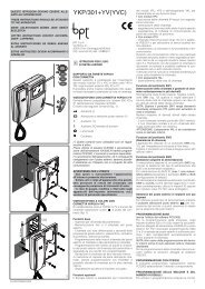
<strong>DC</strong> <strong>JOLLY</strong><br />
Alimentatore elettronico regolabile in corrente continua<br />
per LED ad alta potenza e moduli LED.<br />
DIRECT CURRENT DIMMABLE ELECTRONIC BALLAST FOR HIGH POWER LED<br />
AND LED MODULES.<br />
equiv.<br />
<strong>SELV</strong><br />
ISTRUZIONI DI UTILIZZO<br />
OPERATING INSTRUCTIONS
I<br />
Alimentatore <strong>DC</strong> <strong>JOLLY</strong><br />
equiv.<br />
<strong>SELV</strong><br />
<strong>DC</strong> Jolly è un alimentatore per LED in grado di alimentare sia strisce Led in tensione<br />
(10 V 12 V 24 V) sia LED di potenza alimentati in corrente (350mA, 500mA, 700mA).<br />
La modalità di funzionamento è selezionata attraverso il DIP Switch posto al disotto<br />
del coprimorsetto secondo la seguente tabella.<br />
Posizione DIP 1 2 3 4 5 6<br />
15 W 350mA - - - - - -<br />
22 W 500mA - - - - - ON<br />
25 W 700mA - - - - ON ON<br />
8 W 10 V - - ON ON ON ON<br />
10 W 12 V - ON - ON ON ON<br />
20 W 24 V ON - - ON ON ON<br />
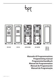
<strong>DC</strong> Jolly è inoltre un alimentatore dimmer in grado di variare la luminosità dei LED<br />
collegati attraverso un segnale di controllo tipo 1÷10 V, potenziometro o pulsante<br />
normalmente aperto. I collegamenti devono essere eseguiti come mostrato nei<br />
seguenti schemi.<br />
103<br />
93,5<br />
21<br />
67<br />
57,5<br />
2
Schema con 1÷10 V o potenziometro<br />
500mA<br />
700mA<br />
I<br />
+<br />
_<br />
SYNC<br />
SEC<br />
1...10 V<br />
10 V<br />
12 V<br />
24 V<br />
+<br />
_<br />
+<br />
_<br />
+<br />
_<br />
LED<br />
1...10 V<br />
PUSH<br />
N<br />
PRI<br />
L<br />
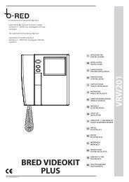
Schema con pulsante<br />
500mA<br />
700mA<br />
10 V<br />
12 V<br />
24 V<br />
+<br />
_<br />
+<br />
_<br />
SYNC<br />
SEC<br />
1...10 V<br />
PRI<br />
+<br />
_<br />
+<br />
_<br />
PUSH<br />
N<br />
L<br />
LED<br />
PUSH<br />
N<br />
L<br />
3
I<br />
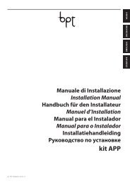
Schema in serie sincronizzati<br />
500mA<br />
700mA<br />
10 V<br />
12 V<br />
24 V<br />
+<br />
_<br />
+<br />
_<br />
SYNC<br />
SEC<br />
+<br />
_<br />
SYNC<br />
1...10 V<br />
+<br />
_<br />
PUSH<br />
N<br />
PRI<br />
L<br />
SYNC<br />
500mA<br />
700mA<br />
10 V<br />
12 V<br />
+<br />
_<br />
24 V<br />
+<br />
_<br />
SYNC<br />
SEC<br />
1...10 V<br />
PRI<br />
+<br />
_<br />
+<br />
_<br />
PUSH<br />
N<br />
L<br />
LED<br />
PUSH<br />
N<br />
L<br />
E’ possibile la sincronizzazione del funzionamento durante la regolazione di più<br />
alimentatori tramite le porte sync. In questo modo si avrà la stessa luminosità<br />
(a parità di carico LED collegato) tra tutti gli alimentatori collegati. Questa possibilità<br />
è estremamente consigliata quando con un pulsate si vogliono comandare più<br />
alimentatori.<br />
4
Funzionamento dell’alimentatore<br />
Funzionamento con 1÷10 V<br />
La luminosità dei led varia proporzionatamente al segnale inviato al morsetto.<br />
La luminosità è nulla con segnale minore di 1 V.<br />
I<br />
Funzionamento con potenziometro<br />
Ruotando il potenziometro si ha la variazione della luminosità dei LED in modo<br />
proporzionale o logaritmico a seconda del modello di potenziometro utilizzato.<br />
Si consiglia l’utilizzo di un potenziometro logaritmico.<br />
Funzionamento con pulsante<br />
Premendo il pulsante per un tempo inferiore a un secondo si ha l’accensione o lo<br />
spegnimento dei LED.<br />
Premendo il pulsante per un tempo superiore a un secondo si ha la regolazione della<br />
luminosità dei LED secondo le seguenti modalità:<br />
• Se la luminosità non è al massimo, premendo il tasto si avrà un incremento di<br />
questa fino al massimo o fino al livello corrispondente al momento in cui si<br />
rilascia il tasto.<br />
• Un ulteriore pressione del tasto inverte il verso di regolazione fino al valore<br />
minimo o fino al livello corrispondente al momento in cui si rilascia il tasto.<br />
• Se la luminosità è al massimo premendo il tasto si avrà un decremento di<br />
questa fino al valore minimo o fino al livello corrispondente al momento in cui si<br />
rilascia il tasto.<br />
Nota Bene:<br />
L’utilizzo del pulsante inibisce l’uso del segnale 1÷10 V. Per tornare<br />
all’utilizzo del segnale 1÷10 V tenere il segnale minore di 0,5 V per almeno<br />
2 secondi.<br />
5
I<br />
Dati tecnici<br />
Ingresso<br />
• Nominale: 220/240 Vac -10/+10 % 50/60Hz.<br />
• Morsettiera 1 x 1,5 mm 2 .<br />
• Corrente massima: 0,16 A<br />
• Fattore di potenza λ: 0,95<br />
• Armoniche corrente assorbita: secondo EN 61000-3-2.<br />
Uscita<br />
• Isolamento Equiv. <strong>SELV</strong>.<br />
• Morsettiera 1 x 1,5 mm 2 .<br />
• Selezione corrente e tensione di uscita tramite DIP switch (vedi tabella).<br />
• Potenza massima e precisione di corrente:<br />
25 W @ 700mA ± 5% (2….36V);<br />
22 W @ 500mA ± 5% (2….43V);<br />
15 W @ 350mA ± 6% (2….43V);<br />
20 W @ 24.5V ± 5% (900mA max);<br />
10 W @ 12.5V ± 5% (900mA max);<br />
9 W @ 10.5V ± 7% (900mA max).<br />
• Tensione in uscita massima: 46 V<strong>DC</strong>.<br />
• Possibilità accensione LED al secondario.<br />
Regolazione<br />
• Tipo PWM comandata da segnale 1÷10 V, potenziometro 100 K o pulsante.<br />
• Segnale 1÷10 V e potenziometro collegabile sul lato secondario.<br />
• Pulsante collegabile su lato primario tra fase e morsetto dedicato.<br />
• Connettori per sincronizzazione più alimentatori (1 master + 9 slaves max).<br />
Protezioni<br />
• All’ingresso, contro sovratensioni impulsive di rete (secondo EN 61547).<br />
• Protezione al corto circuito.<br />
• Protezione al sovraccarico e di temperatura.<br />
Filtro Antidisturbi EMI<br />
• Secondo EN55015.<br />
6
Ambiente<br />
• Temp. ambiente: -20…50 °C.<br />
• tc = 75 °C.<br />
• tc life 50000H = 70°C.<br />
I<br />
Sicurezza<br />
• Hi-pot test: 3,75 kV, 100% per 2 sec.<br />
Normative<br />
• EN 61347-1 ; EN 61347-2-11 ; EN 61547; EN 55015; EN 61000-3-2;<br />
DIN VDE 0710 teil 14.<br />
• KEMA KEUR pending.<br />
7
Alimentatore <strong>DC</strong> <strong>JOLLY</strong><br />
GB<br />
equiv.<br />
<strong>SELV</strong><br />
<strong>DC</strong> Jolly is a ballast for LEDs which can power both voltage LED strips (10V 12V 24V)<br />
and power current powered LEDs (350mA, 500mA, 700mA).<br />
The function mode is selected by means of the DIP switch, which is below the terminal<br />
cover, according to the following table.<br />
DIP position 1 2 3 4 5 6<br />
15 W 350mA - - - - - -<br />
22 W 500mA - - - - - ON<br />
25 W 700mA - - - - ON ON<br />
8 W 10 V - - ON ON ON ON<br />
10 W 12 V - ON - ON ON ON<br />
20 W 24 V ON - - ON ON ON<br />
Moreover, <strong>DC</strong> Jolly is a dimmer ballast which can vary the light intensity of the<br />
connected LEDs by means of a type 1÷10V control signal, potentiometer or normally<br />
open push button. The connections must be carried out as shown in the following<br />
diagrams.<br />
103<br />
93,5<br />
21<br />
67<br />
57,5<br />
8
Diagram with 1÷10 V or potentiometer<br />
+<br />
_<br />
SYNC<br />
SEC<br />
1...10 V<br />
500mA<br />
700mA<br />
10 V<br />
12 V<br />
24 V<br />
+<br />
_<br />
+<br />
_<br />
+<br />
_<br />
LED<br />
1...10 V<br />
GB<br />
PUSH<br />
N<br />
PRI<br />
L<br />
Diagram with push button<br />
500mA<br />
700mA<br />
10 V<br />
12 V<br />
24 V<br />
+<br />
_<br />
+<br />
_<br />
SYNC<br />
SEC<br />
1...10 V<br />
PRI<br />
+<br />
_<br />
+<br />
_<br />
PUSH<br />
N<br />
L<br />
LED<br />
PUSH<br />
N<br />
L<br />
9
Diagram function synchronization<br />
GB<br />
500mA<br />
700mA<br />
10 V<br />
12 V<br />
24 V<br />
+<br />
_<br />
+<br />
_<br />
SYNC<br />
SEC<br />
1...10 V<br />
+<br />
_<br />
+<br />
_<br />
SYNC<br />
PUSH<br />
N<br />
PRI<br />
L<br />
SYNC<br />
10 V<br />
12 V<br />
+<br />
_<br />
24 V<br />
+<br />
_<br />
SYNC<br />
SEC<br />
1...10 V<br />
PRI<br />
+<br />
_<br />
+<br />
_<br />
PUSH<br />
N<br />
L<br />
500mA<br />
700mA<br />
LED<br />
PUSH<br />
N<br />
L<br />
Function synchronization during dimming of more than one ballast is possible by<br />
means of the sync gates. In this way there is the same light intensity (with the<br />
same connected led load) among all the connected ballasts. This possibility is<br />
highly recommended when more than one ballast needs to be controlled by one<br />
push button.<br />
10
Ballast function<br />
1÷10 V function<br />
The light intensity of the LEDs vary proportionally to the signal sent to the terminal.<br />
Intensity is null with a signal less than 1 V.<br />
Potentiometer function<br />
By rotating the potentiometer there is variation of the LED light intensity in a proportionate<br />
or logarithmic way depending on the model of potentiometer used. The use<br />
of a logarithmic potentiometer is recommended.<br />
Push button function<br />
By pressing the push button for less than one second the LEDs turn on or off.<br />
By pressing the push button for more than one second the light intensity of the LEDs<br />
is dimmed according to the following modalities:<br />
If the light intensity is not at maximum, by pressing the key there will be an increase<br />
of this to maximum or to the corresponding level at the moment the key is released.<br />
A further pressure on the key inverts the dimming direction to the minimum value or<br />
to the corresponding level at the moment the key is released.<br />
If light intensity is at maximum by pressing the key there will be a decrease to the<br />
minimum value or to the corresponding level at the moment the key is released.<br />
N.B.:<br />
The use of the push button inhibits the use of the 1÷10 V signal.<br />
To return to use of the 1÷10 V signal keep the signal less than 0,5 V for at<br />
least 2 seconds.<br />
GB<br />
11
GB<br />
Technical data<br />
Input<br />
• Nominal: 220/240 Vac -10/+10 % 50/60Hz.<br />
• Terminal block for up to 1 x 1.5 mm 2 .<br />
• Max Input Current: 0.16 A.<br />
• Power factor λ: 0.95.<br />
• Harmonic content of mains current: ac-cording to EN 61000-3-2.<br />
Output<br />
• Equiv. <strong>SELV</strong> insulation on output.<br />
• Terminal block for up to 1 x 1.5 mm 2 .<br />
• Selection of current and voltage output through Dip switch (See table)<br />
• Max output power and current preci-sion:<br />
25 W@ 700mA ± 5% (2….36V);<br />
22 W@ 500mA ± 5% (2….43V);<br />
15 W@ 350mA ± 6% (2….43V);<br />
20 W @ 24.5V ± 5% (900mA max);<br />
10 W @ 12.5 V± 5% (900mA max);<br />
9 W @ 10.5V ± 7% (900mA max).<br />
• Max. Output voltage: 46 V<strong>DC</strong>.<br />
• Possibility of switch on the LED on secon-dary side<br />
Dimming<br />
• PWM controlled by 1÷10 V signal, 100 K potenziometer or pushbutton.<br />
• Terminal block on the secondary side for 1÷10V Signal or potenziometer.<br />
• Terminal block on primary side for push button; connection between phase<br />
and terminal block .<br />
• Header for other power supplier syn-chronization (1master + 9 slaves max).<br />
Protections<br />
• Against input overvoltages from mains ( according to EN61547).<br />
• Against short circuit.<br />
• Thermal and overload protection.<br />
EMI<br />
• According to EN55015.<br />
12
Ambient<br />
• Ambient temp.: -20….50 °C.<br />
• tc = 75 °C.<br />
• tc life 50000H = 70°C.<br />
GB<br />
Safety<br />
• Hi-pot test: 3.75 kV, 100% for 2 sec.<br />
Standards<br />
• EN 61347-1; EN 61347-2-11; EN 61547; EN 55015; EN 61000-3-2;<br />
DIN VDE 0710 teil 14.<br />
• KEMA KEUR pending.<br />
13
GARANZIA<br />
I prodotti sono garantiti per 24 mesi dalla data di fabbricazione. La garanzia<br />
copre tutti gli eventuali difetti di fabbricazione. La garanzia non copre gli<br />
eventuali difetti e/o danni causati da utilizzo errato o non conforme alle istruzioni<br />
di installazione ed impiego. La garanzia decade se i prodotti vengono<br />
aperti o manomessi.<br />
Nota<br />
La Società si riserva la possibilità, nel rispetto delle norme in vigore, di apportare,<br />
senza preavviso, modifiche tecniche e dimensionali per migliorare le caratteristiche e<br />
le prestazioni dei prodotti.<br />
warranty<br />
Our products are guaranteed for 24 months from the date of manufacture. Our warranty<br />
covers all manufacturing defects. Our warranty does not cover defects and/or damages<br />
due to improper use or not conforming to the operating and installation instructions.<br />
The warranty will be invalidated if the products are opened or tampered with.<br />
Note<br />
According to the regulations in force, the Manufacturer reserves the right to make<br />
technical and dimensional changes to improve product characteristics and performance<br />
without prior notice.
Direttiva UE 2002/96/EC (RAEE)<br />
Informazioni agli utenti<br />
Questo prodotto è conforme alla direttiva 2002/96/EC.<br />
II simbolo del cestino barrato riportato sull’apparecchio indica che il prodotto,<br />
alla fine della propria vita utile,dovendo essere trattato separatamente dai rifiuti<br />
domestici, deve essere conferito in un centro di raccolta differenziata per<br />
apparecchiature elettriche ed elettroniche oppure riconsegnato al rivenditore al<br />
momento dell’acquisto di una nuova apparecchiatura equivalente. L’utente<br />
è responsabile del conferimento dell’apparecchio a fine vita alle appropriate<br />
strutture di raccolta.<br />
L’adeguata raccolta differenziata per l’avvio successivo dell’apparecchio dismesso al<br />
riciclaggio, al trattamento e allo smaltimento ambientalmente compatibile contribuisce<br />
ad evitare possibili effetti negativi sull’ambiente, sulla salute e favorisce il riciclo dei<br />
materiali di cui è composto il prodotto.<br />
Lo smaltimento abusivo del prodotto da parte dell’utente è sanzionato dalla legge. Per<br />
informazioni più dettagliate inerenti i sistemi di raccolta disponibili, rivolgersi al servizio<br />
locale di smaltimento rifiuti, o al negozio in cui è stato effettuato l’acquisto.<br />
Directive UE 2002/96/EC (WEEE)<br />
Information for users<br />
This product conforms with EU directive 2002/96/EC.<br />
It carries the symbol of the crossed-out waste bin, which means that once its useful life<br />
is over it must be treated separately from other domestic waste: it must be taken to a<br />
recycling centre for electrical and electronic equipment, or taken back to a retailer and<br />
left there when a new equivalent device is purchased. The user is responsible, when<br />
the device is to be disposed of, for taking it to the appropriate collection point.<br />
Proper differentiated collection is necessary so that the obsolete device can be sent<br />
on for environmental friendly recycling, treatment and dismantling, in order to avoid<br />
any possible negative environmental impact or health risk and to allow the materials<br />
of which it is made to be re-used.<br />
More detailed information about available systems for collection may be obtained<br />
from the local waste disposal services, or from the shop from which the device was<br />
purchased.
21047 Saronno (VA) Italy - Via Parma,14 - Tel +39 02964161 Fax +39 029608247<br />
tci@tci.it - www.tci.it