ceLLe dI caRIco LOAD CELLS - Manupala industrie
ceLLe dI caRIco LOAD CELLS - Manupala industrie
ceLLe dI caRIco LOAD CELLS - Manupala industrie

Create successful ePaper yourself
Turn your PDF publications into a flip-book with our unique Google optimized e-Paper software.
<strong>ceLLe</strong> <strong>dI</strong> <strong>caRIco</strong><br />
<strong>LOAD</strong> <strong>CELLS</strong><br />
1
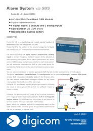
Misurare con precisione e mantenere costante la tensione di un<br />
nastro in movimento è essenziale per ottenere una qualità costante<br />
del prodotto e massimizzar(n)e la produttività.<br />
Le celle di carico della Re, all’interno di un accurato sistema di<br />
controllo della tensione, sono state studiate per adempiere a<br />
questi delicati compiti e ne decretano il successo sia sotto l’aspetto<br />
qualitativo che per il prezzo, nel rispetto delle aspettative ed<br />
esigenze della nostra clientela.<br />
Le celle Re possono essere utilizzate per misurare il valore della<br />
tensione in differenti settori: carta, cartone, film plastici, lamiera,<br />
gomma, tessuto, filo metallico; possono essere installate sia nella<br />
zona di avvolgimento, che in quella di processo e svolgimento.<br />
TECNOLOGIA STRAIN GAUGES<br />
Il principio di funzionamento ad estensimetri (strain gauges), che<br />
è il metodo più utilizzato per la misurazione ed il controllo della<br />
tensione di un laminto, è la chiave del successo delle nostre celle<br />
di carico.<br />
Gli strain gauges sono resistori presenti su una lamina interna di<br />
una cella di carico e connessi tra di loro a ponte Wheatstone, in<br />
grado di convertire un movimento meccanico in segnale elettrico<br />
che dovrà poi essere amplificato dagli appositi amplificatori.<br />
celle di carico / <strong>LOAD</strong> <strong>CELLS</strong><br />
m a d e i n I t a l y<br />
Precisely measuring and keeping constant the tension of a moving<br />
web is essential in order to obtain constant product quality and to<br />
maximise productivity.<br />
Re load cells, in a precise tension control system, are designed<br />
to carry out these delicate tasks and determine their success in<br />
terms of both quality and price, meeting our customers’ needs and<br />
expectations.<br />
Re cells can be used to measure tension in various sectors: paper,<br />
cardboard, plastic film, sheet metal, rubber, fabric, metal wire.<br />
They can be installed both in the winding zone and in the process<br />
and unwinding zone.<br />
STRAIN GAUGES TECHNOLOGY<br />
The strain gauges operating principle, which is the most widely<br />
used method for measuring and controlling web tension, is the key<br />
to the success of our load cells.<br />
Strain gauges resistors present on a inner metal foil of a load cell<br />
and connected to each other in a “Wheatstone bridge”, able to<br />
covert a mechanical movement into an electrical signal which must<br />
then be amplified by suitable amplifiers.<br />
2 3
GUIDA ALLA SCELTA<br />
DELLA CELLA DI CARICO<br />
GUIDE FOR <strong>LOAD</strong> CELL SELECTION<br />
SIMBOLI<br />
E UNITÀ DI MISURA<br />
• = Direzione risultante<br />
SYMBOLS<br />
AND UNIT<br />
OF MEASUREMENT<br />
• = Resultant direction<br />
wrap angle<br />
α<br />
wrap angle<br />
α<br />
wrap angle<br />
α<br />
α/2<br />
α/2<br />
α/2<br />
Tension (T)<br />
Tension (T)<br />
Tension (T)<br />
Roller<br />
Roller<br />
Per scegliere la cella di carico adatta alle proprie esigenze<br />
è necessario stabilire la capacità di carico che essa dovrà<br />
sostenere; bisognerà dunque calcolare la forza risultante (F) che<br />
sarà prodotta dalla tensione del laminato sul rullo (T) in base ad<br />
uno specifico “angolo di avvolgimento” (α).<br />
α<br />
F<br />
Ft<br />
= Angolo di avvolgimento [gradi]<br />
= Risultante sulla cella [N]<br />
= Forza della tensione [N]<br />
α<br />
F<br />
Ft<br />
= Winding angles [degrees]<br />
= Resultant on cell [N]<br />
= Force of tension [N]<br />
Tension (T)<br />
Tension (T)<br />
Tension (T)<br />
Proller<br />
Proller<br />
Proller<br />
Roller<br />
Ftension<br />
Ftension<br />
Ftension<br />
Ft = 2 Tension (T) · sin (α/2)<br />
To select the load cell suited to your needs, you must find<br />
out the load capacity that the cell must withstand. Therefore,<br />
calculate the resultant force (F) that will be produced by the<br />
tension of the web on the roller (T) based on a specific “wrap<br />
angle” (α).<br />
Fl.c. = Forza per cella di carico [N]<br />
Fl.c. = Force per load cell [N]<br />
wrap angle<br />
α<br />
Tension (T)<br />
T<br />
P<br />
= Tensione totale del laminato [N]<br />
= Peso del rullo [N]<br />
T<br />
P<br />
= Total tension of web [N]<br />
= Weight of roll [N]<br />
wrap angle<br />
α<br />
wrap angle<br />
α<br />
α/2<br />
α/2<br />
α/2<br />
Tension (T)<br />
Tension (T)<br />
Roller<br />
Roller<br />
La tensione del laminato non è l’unica forza esercitata sul rullo<br />
in quanto la forza risultante è anche influenzata dal peso del<br />
rullo stesso (P). Per calcolare la capacità di carico che una cella<br />
dovrà sostenere sarà necessario sommare il vettore della forza di<br />
tensione con quello del peso del rullo.<br />
Tension (T)<br />
Tension (T)<br />
Tension (T)<br />
Proller<br />
Proller<br />
Proller<br />
Roller<br />
Ftension<br />
Ftension<br />
Ftension<br />
Proller<br />
F = Ft + P<br />
The tension of the laminate is not the only force applied on the<br />
roller, since the resultant force (F) is also affected by the weight<br />
of the roller itself (P) which must be added to the tension (T).<br />
To calculate the load capacity that a cell must withstand, add the<br />
tension force vector to the roller weight vector.<br />
Proller<br />
Proller<br />
wrap angle<br />
α<br />
wrap angle<br />
α<br />
wrap angle<br />
α<br />
α/2<br />
α/2<br />
α/2<br />
Tension (T)<br />
Tension (T)<br />
Tension (T)<br />
Roller<br />
Nei casi di applicazioni di celle non a sbalzo la forza sarà<br />
distribuita su tutte e due le celle; per calcolare la capacità di<br />
carico di ciascuna sarà necessario dividere la forza per 2.<br />
Fl.c. = 1/2 (Ft + P)<br />
Tension (T)<br />
Proller<br />
Roller<br />
Roller<br />
Ftension<br />
Ftension<br />
In all applications (except for cantilever cells) the force will be<br />
distributed on both cells. To calculate the load capacity of each,<br />
divide the force by 2.<br />
Tension (T)<br />
Tension (T)<br />
Proller<br />
Proller<br />
Ftension<br />
Proller<br />
Proller<br />
Proller<br />
4 5
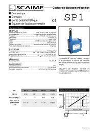
CALCOLO DELLA RISULTANTE<br />
RESULTANT CALCULATION<br />
T<br />
F<br />
α<br />
T P=0<br />
F= T sin α/2<br />
T<br />
α<br />
F<br />
T<br />
P<br />
ß<br />
F= T sin α/2 + P/2 cosβ<br />
ß<br />
T<br />
F<br />
Risultante orizzontale<br />
La risultante orizzontale è la configurazione migliore per le celle di<br />
carico in quanto non rileva il peso del rullo. Tale configurazione è<br />
consigliabile per una tensione del nastro bassa.<br />
Horizontal resultant<br />
Horizontal resultant is the best configuration for load cells, since<br />
it does not detect the weight of the roller. That configuration is<br />
recommended for low web tension.<br />
Risultante verso il basso<br />
Nella configurazione con risultante verso il basso il peso del rullo (P)<br />
fornisce un segnale positivo che sarà considerato tara. Lo zero-set<br />
viene ottenuto sottraendo elettricamente il valore del peso del rullo.<br />
Downward resultant<br />
In the configuration with downward resultant the weight of the roller<br />
(P) supplies a positive signal which will be considered the tare. For a<br />
zero-set electrically subtract the roller weight value.<br />
Risultante verso l’alto<br />
Nella configurazione con risultante verso l’alto il peso del rullo (P?)<br />
fornisce un segnale negativo che sarà considerato come tara e dovrà<br />
essere ridotto elettricamente allo “zero” durante la calibrazione della<br />
cella di carico.<br />
CELLE DI CARICO A FLANGIA<br />
SERIE CF<br />
CF SERIES <strong>LOAD</strong> <strong>CELLS</strong><br />
FLANGE MOUNTED<br />
La serie CF è la categoria di celle di carico a flangia della RE.<br />
Vengono installate all’estremità di un rullo di misura e sono in<br />
grado di rilevare con precisione la risultante delle forze generate<br />
dal tiro del materiale in funzione degli angoli di avvolgimento.<br />
Il successo commerciale delle celle CF è dovuto alla combinazione<br />
tra il loro disegno compatto, che ne permette un facile montaggio<br />
in spazi ristretti, un utilizzo semplice ed un’elevata affidabilità,<br />
dovuta allo standard qualitativo raggiunto dalla Re nei circa 30<br />
anni di attività nel settore.<br />
Le celle di carico CF sono disponibili in diversi modelli e con un<br />
range di carico da 50N a 2000N.<br />
The CF series is the RE flanged load cell category. They are fitted<br />
at the end of a measuring roller and can precisely detect the result<br />
of the forces generated by pulling of the material depending on<br />
the winding angles.<br />
The commercial success of CF cells is due to the combination of<br />
their compact design, which allows them to be easily fitted in<br />
narrow spaces, user-friendliness and high reliability, thanks to<br />
the high quality achieved by RE in 30 years of business in the<br />
sector.<br />
CF load cells are available in various models and with a load<br />
range of from 50N to 20000N<br />
caratteristiche principali:<br />
• disegno compatto<br />
• Utilizzo semplice<br />
• Affidabilità<br />
• Range di carico da 50N a 20000N<br />
Main features:<br />
• Compact size<br />
• Ease of use<br />
• Reliability<br />
• Load range: from 50N to 20000N<br />
α<br />
P<br />
T<br />
Upward resultant<br />
In the configuration with upward resultant the weight of the roller (P)<br />
supplies a negative signal which will be considered as the tare and<br />
must be electrically reduced to “zero” during load cell calibration.<br />
F= T sin α/2 - P/2 cosβ<br />
Dati tecnici<br />
Technical data<br />
classe di precisione: 0,5% Precision class: 0.5%<br />
Principio di misura: con estensimetri a ponte<br />
completo 350Ω OHM<br />
errore totale – ripetibilità – isteresi – linearità:<br />
5 mt<br />
Sensitività (out voltage)<br />
Normal: from 1,5 mV/V to 2,0 mV/V<br />
Supply: 10 V - max 15 V<br />
As an option we offer the load cells with a 4-20 mA<br />
signal. In this case a preamplifier is assembled into<br />
the load cell. This option is recommended where the<br />
cable connecting the load cells to the signal receiver<br />
are greater than 5 mt in length, as this may cause a<br />
voltage drop in the standard mV range.<br />
Raccomandazioni per l’installazione corretta delle celle CF<br />
Montare le celle di carico all’estremità del rullo facendo riferimento<br />
allo schema a fianco.<br />
Bloccare assialmente un cuscinetto con un anello di arresto,<br />
lasciare l’altro libero di scorrere nella sede per compensare le<br />
dilatazioni termiche del rullo.<br />
Numero di celle<br />
È consentito l’impiego di una sola cella solo nelle seguenti<br />
condizioni:<br />
• La lunghezza dell’albero è inferiore a 1000mm<br />
• Il laminato rimane sempre in mezzeria del rullo<br />
Raccomendations for the correct installation of CF’s cells<br />
Assemble the load cells to the shaft ends of the roll as shown in<br />
the drawing to the right.<br />
One bearing is axially fixed using a circlip (retaining ring) and<br />
spacers, while the other bearing is left free to float axially into<br />
the load cell. This allows for thermal expansion of the machine<br />
components.<br />
Number of cells<br />
It is possible to use only 1 load cell in the following cases:<br />
• The length of the roll is less than 40 inches<br />
• The web material constantly remains in the center of the roll or<br />
in the same location on the roller.<br />
6 7
0<br />
CELLE DI CARICO A FLANGIA - SERIE CF<br />
CF SERIES <strong>LOAD</strong> <strong>CELLS</strong> - FLANGE MOUNTED<br />
CF.70<br />
codice<br />
codice<br />
cuscinetto<br />
size of ball<br />
bearing<br />
0<br />
carico (N)<br />
load (N)<br />
6A05001 - 0 ÷ 250<br />
6A05002 - 0 ÷ 500<br />
6A05003 - 0 ÷ 1000<br />
Punto rosso<br />
direzione risultante<br />
Red point<br />
resultant direction<br />
n°4 fori<br />
Ø10.5 sul Ø111<br />
n°4 holes<br />
Ø10.5 on Ø111<br />
Presa a 5 poli<br />
5 poles jack<br />
0<br />
Presa a 4 poli<br />
4 poles jack<br />
Punto rosso<br />
direzione risultante<br />
Red point<br />
resultant direction<br />
Ø69<br />
Ø25H7<br />
n°1 foro M10<br />
n°1 hole M10<br />
0<br />
-0.02<br />
Ø30<br />
M10<br />
3<br />
14<br />
31.5<br />
74.5<br />
26<br />
90°<br />
Ø111<br />
Ø10.5<br />
Ø69.8 -0.03<br />
0<br />
6.5<br />
16<br />
77.3<br />
13<br />
3.6<br />
Ø69.8 + 0.03<br />
0<br />
Ø127<br />
CF.125<br />
codice<br />
codice<br />
cuscinetto<br />
size of ball<br />
bearing<br />
carico (N)<br />
load (N)<br />
CF.125.50 - 0 ÷ 500<br />
CF.125.100 - 0 ÷ 1000<br />
CF.125.175 - 0 ÷ 1750<br />
CF.125.250 - 0 ÷ 2500<br />
CF.85<br />
CF.130<br />
Punto rosso<br />
direzione<br />
risultante<br />
Red point<br />
resultant<br />
direction<br />
Presa a 5 poli<br />
collegare con cavo<br />
schermato a 4<br />
poli-max<br />
lunghezza 25m<br />
sezione cad.filo 05mm<br />
5 poles jack<br />
use a shielding<br />
4 poles wire<br />
max lenght 25m<br />
section 0.5mm<br />
90°<br />
Ø70<br />
Ø85<br />
n°4 fori<br />
Ø6.5 sul Ø70<br />
n°4 holes<br />
Ø6.5 on Ø70<br />
-0.03<br />
Ø50<br />
3<br />
Ø6.5<br />
24<br />
63<br />
Cella con<br />
cuscinetto fisso<br />
Cell with<br />
stationary bearing<br />
5<br />
Ø40<br />
24.5<br />
Cella con<br />
cuscinetto mobile<br />
Cell with<br />
floating bearing<br />
codice<br />
codice<br />
cuscinetto<br />
size of ball<br />
bearing<br />
carico (N)<br />
load (N)<br />
CF.85.5.40 40 x 17 0 ÷ 50<br />
CF.85.15.40 40 x 17 0 ÷ 150<br />
CF.85.25.40 40 x 17 0 ÷ 250<br />
CF.85.50.40 40 x 17 0 ÷ 500<br />
CF.85.100.40 40 x 17 0 ÷ 1000<br />
CF.85.200.40 40 x 17 0 ÷ 2000<br />
Punto rosso<br />
direzione risultante<br />
Red point<br />
resultant direction<br />
n°4 fori<br />
Ø10.5 sul Ø108<br />
n°4 holes<br />
Ø10.5 on Ø108<br />
Presa a 5 poli<br />
5 poles jack<br />
Ø108<br />
Ø81<br />
90°<br />
Ø10.5<br />
M6*15<br />
Ø130<br />
Ø120<br />
5Ø75 H7<br />
13<br />
Ø10.5<br />
B<br />
G1/8<br />
68<br />
98<br />
ØA<br />
Ø90<br />
codice<br />
codice<br />
cuscinetto<br />
size of ball<br />
bearing<br />
A B<br />
carico (N)<br />
load (N)<br />
CF.130.50.72 72 45 0 ÷ 500<br />
CF.130.100.72 72 45 0 ÷ 1000<br />
CF.130.200.72 72 45 0 ÷ 2000<br />
CF.130.500.72 72 45 0 ÷ 5000<br />
Punto rosso<br />
direzione<br />
risultante<br />
Red point<br />
resultant<br />
direction<br />
Presa a 5 poli<br />
5 poles jack<br />
Ø90<br />
Ø118<br />
n°2 fori<br />
Ø12.5 sul Ø90<br />
n°2 holes<br />
Ø12.5 on Ø90<br />
-0.03<br />
Ø60<br />
3<br />
Ø12.5<br />
24<br />
63<br />
3.5<br />
Cella con<br />
cuscinetto fisso<br />
Cell with<br />
stationary bearing<br />
Ø52<br />
27<br />
Cella con<br />
cuscinetto mobile<br />
Cell with<br />
floating bearing<br />
CF.120<br />
codice<br />
codice<br />
cuscinetto<br />
size of ball<br />
bearing<br />
carico (N)<br />
load (N)<br />
CF.120.25.52 52 x 25 0 ÷ 150<br />
CF.120.50.52 52 x 25 0 ÷ 250<br />
CF.120.100.52 52 x 25 0 ÷ 500<br />
CF.120.200.52 52 x 25 0 ÷ 1000<br />
Punto rosso<br />
direzione<br />
risultante<br />
Red point<br />
resultant<br />
direction<br />
Presa a 5 poli<br />
5 poles jack<br />
Ø185<br />
45°<br />
45°<br />
22.5°<br />
Ø210<br />
-0.03<br />
Ø120<br />
n°8 fori<br />
Ø12.5 sul Ø185<br />
n°8 holes<br />
Ø12.5 on Ø185<br />
Ø12.5<br />
5<br />
18 18<br />
5<br />
49.5<br />
110<br />
Ø165 0 -0.03<br />
CF.200<br />
codice<br />
codice<br />
cuscinetto<br />
size of ball<br />
bearing<br />
carico (N)<br />
load (N)<br />
CF.200.500 - 0 ÷ 5000<br />
CF.200.1000 - 0 ÷ 10000<br />
CF.200.1500 - 0 ÷ 15000<br />
CF.200.2000 - 0 ÷ 20000<br />
CF.200.2500 - 0 ÷ 25000<br />
8 9
CELLE DI CARICO CON FORO PASSANTE<br />
SERIE CK<br />
CK SERIES <strong>LOAD</strong> <strong>CELLS</strong><br />
THROUGH SHAFT<br />
Punto rosso<br />
direzione risultante<br />
Red point<br />
resultant direction<br />
SERIE CK<br />
CK SERIES<br />
Compatte, versatili ed affidabili, queste celle sono un’alternativa<br />
a quelle a flangia ma con la possibilità di essere impiegate in<br />
presenza di alberi passanti.<br />
Le celle della serie cK rilevano e misurano le forze applicate alle<br />
stesse e forniscono un segnale elettrico proporzionale, ripetibile<br />
e privo di isteresi che può essere gestito per la lettura del carico<br />
ed ogni tipo di regolazione.<br />
La serie cK è dotata degli stessi elevati standard qualitativi della<br />
produzione della Re e pertanto usufruiscono di tutta la nostra<br />
tecnologia ed esperienza acquisita in 30 anni di attività nel<br />
settore.<br />
ØD<br />
ØA<br />
ØC<br />
ØB g6<br />
ØE<br />
Compact, versatile and reliable, these cells offer an alternative<br />
to the others manufactured by Re and are used for through shaft<br />
assembly application.<br />
The CK load cells measure the applied force and give an electric<br />
proportional signal, repeatable and free from hysteresys, which<br />
can be used for any kind of regulation.<br />
CK load cells are the product of over 30 years of experience gain<br />
in the field of tension regulation.<br />
G<br />
54 49<br />
M<br />
H<br />
I<br />
M<br />
ØF<br />
caratteristiche principali:<br />
• disegno compatto<br />
• Versatilità<br />
• Affidabilità<br />
• Utilizzate in presenza di alberi passanti<br />
• Range di carico da 250N a 30000N<br />
Main features:<br />
• Compact size<br />
• Versatility<br />
• Reliability<br />
• Through-shaft design<br />
• Load range: from 250N to 30000N<br />
codice / codice<br />
Tipo standard / Standard type<br />
carico (N)<br />
load (N)<br />
Tipo 90° / 90° type<br />
dimensioni mm / dimensions mm<br />
A B C D H I G E F M<br />
CK.100.25.12 0 ÷ 250 12 50 16 100 14 36,5 85,5 70 6,5 3<br />
CK.105.50.17 0 ÷ 500 17 60 22 105 16 36,5 88 75 6,5 3<br />
CK.105.100.17 0 ÷ 1000 17 60 22 105 16 36,5 88 75 6,5 3<br />
CK.125.75.25 0 ÷ 750 25 70 31 125 18 47,5 98 95 6,5 4<br />
CK.125.150.25 0 ÷ 1500 25 70 31 125 18 47,5 98 95 6,5 4<br />
CK.175.100.35 0 ÷ 1000 35 100 44 175 23 65 123 135 8,5 4<br />
CK.175.150.35 0 ÷ 1500 35 100 44 175 23 65 123 135 8,5 4<br />
CK.175.300.35 0 ÷ 3000 35 100 44 175 23 65 123 135 8,5 4<br />
CK.225.300.50 0 ÷ 3000 50 130 58 225 23 75 148 175 10,5 4<br />
CK.225.600.50 0 ÷ 6000 50 130 58 225 23 75 148 175 10,5 4<br />
CK.265.500.65 0 ÷ 5000 65 160 80 265 33 80 168 220 10,5 4<br />
CK.265.1000.65 0 ÷ 10000 65 160 80 265 33 80 168 220 10,5 4<br />
CK.265.2000.65 0 ÷ 20000 65 160 80 265 33 80 168 220 10,5 4<br />
CK.265.3000.80 0 ÷ 30000 80 160 80 265 33 80 168 220 10,5 4<br />
10 11
CELLE DI CARICO A BASAMENTO<br />
SERIE CB<br />
CB SERIES <strong>LOAD</strong> <strong>CELLS</strong> - BASE STYLE<br />
80<br />
35<br />
CB.70<br />
CB.200<br />
La serie cB è la categoria di celle di carico della Re a basamento.<br />
esse offrono la soluzione ideale per il rilevamento della tensione<br />
del laminato in quanto hanno la prerogativa di misurarla senza<br />
l’influenza di altre forza come il peso dei rulli, i supporti, ecc.<br />
La struttura delle celle cB permette l’annullamento della tara<br />
in modo meccanico e non elettrico come nelle altre tipologie di<br />
celle; inoltre esse offrono una resistenza elevata alle vibrazioni<br />
ed ai sovraccarichi.<br />
Le celle cB vengono applicate in particolar modo su continue per<br />
cartiere, supercalandre e laminatoi, ma anche su impianti in cui<br />
il laminato deve essere trattato con estrema cura ed attenzione.<br />
The CB series is the RE base load cell range. They offer the<br />
ideal solution for detecting laminate tension because they can<br />
measure it without the influence of other forces such as the<br />
weight of the rollers, the supports, etc.<br />
The structure of CB cells allows the tare to be eliminated<br />
mechanically rather than electrically as happens with other<br />
types of cells. Plus, they offer high resistance to vibrations and<br />
overloads.<br />
CB cells are applied in particular on paper mill, supercalendering<br />
and rolling machines, but also on plants in which laminate must<br />
be treated with extreme care and attention.<br />
80<br />
153.5<br />
153.5<br />
80<br />
150 50<br />
80<br />
35<br />
M6<br />
35<br />
35<br />
M6<br />
M6*10(Max)<br />
M6*10(Max)<br />
150 50<br />
6<br />
10<br />
51<br />
6<br />
10<br />
51<br />
57<br />
22<br />
12<br />
57<br />
22<br />
12<br />
35 +0.1<br />
-0.1<br />
35 +0.1<br />
-0.1<br />
70<br />
70<br />
codice<br />
codice<br />
carico (N)<br />
load (N)<br />
CB.70.15 0 ÷ 150<br />
CB.70.25 0 ÷ 250<br />
CB.70.50 0 ÷ 500<br />
CB.70.100 0 ÷ 1000<br />
CB.70.200 0 ÷ 2000<br />
caratteristiche principali:<br />
• Per elevati carichi (fino a 30000N)<br />
• Facile montaggio con supporti cuscinetti<br />
• Risultante parallela al piano di appoggio<br />
26<br />
50 10<br />
80<br />
CB.80<br />
CB.300<br />
Main features:<br />
• High loads (from 150 N to 30000 N)<br />
• Easy to fit with bearing supports<br />
• Resultant parallel with supporting surface<br />
40<br />
26,3<br />
10<br />
160<br />
180<br />
26<br />
10<br />
20<br />
50 10<br />
80<br />
96<br />
α<br />
P=0<br />
β<br />
S<br />
40<br />
26,3<br />
10<br />
160<br />
180<br />
8,5<br />
8,5<br />
25<br />
25<br />
10<br />
16<br />
= =<br />
20<br />
16<br />
= =<br />
10 70<br />
10<br />
10 70<br />
10<br />
90<br />
90<br />
Punto rosso<br />
direzione risultante<br />
Red point<br />
resultant direction 96<br />
Punto rosso<br />
direzione risultante<br />
Red point<br />
resultant direction<br />
codice<br />
codice<br />
carico (N)<br />
load (N)<br />
CB.80.25 0 ÷ 250<br />
CB.80.50 0 ÷ 500<br />
CB.80.100 0 ÷ 1000<br />
CB.80.200 0 ÷ 2000<br />
β < α<br />
12 13
CELLE DI CARICO A BASAMENTO<br />
SERIE CB<br />
CB SERIES <strong>LOAD</strong> <strong>CELLS</strong> - BASE STYLE<br />
CB.200<br />
CELLE DI CARICO CON RULLO A SBALZO<br />
SERIE CP.35<br />
CANTILEVER <strong>LOAD</strong> <strong>CELLS</strong> - CP.35<br />
230<br />
76<br />
16<br />
16.6<br />
230<br />
170 +0.1<br />
-0.1<br />
M12<br />
M12<br />
125<br />
125<br />
50 +0.1<br />
-0.1<br />
76<br />
50 +0.1<br />
-0.1<br />
M12<br />
22<br />
22<br />
codice<br />
codice<br />
carico (N)<br />
load (N)<br />
CB.200.250 0 ÷ 2500<br />
CB.200.500 0 ÷ 5000<br />
CB.200.1000 0 ÷ 10000<br />
CB.200.2000 0 ÷ 20000<br />
CB.200.3000 0 ÷ 30000<br />
La cP.35 è la cella di carico con rullo a sbalzo della Re. Il suo<br />
design specializzato permette la risoluzione di molti problemi di<br />
applicazione e dimostra l’esperienza che abbiamo acquisito negli<br />
anni.<br />
The CP series is Re’s cantilever load cell line. It is a specialized<br />
design and demonstrates Re’s experience in designing and<br />
manufacturing customized load cells to solve specific application<br />
problems.<br />
16<br />
16.6<br />
24 16<br />
170 +0.1<br />
-0.1<br />
24 16<br />
M12<br />
Punto rosso<br />
direzione risultante<br />
Red point<br />
resultant direction<br />
Punto rosso<br />
direzione risultante<br />
Red point<br />
resultant direction<br />
Lunghezza cavo 5 mt.<br />
Cable’s lenght 5 mt.<br />
Ø33<br />
Ø35h7<br />
Ø39<br />
Ø75<br />
16.6<br />
320<br />
104<br />
1.6<br />
M16<br />
70<br />
CB.300<br />
96.6<br />
33.5 33.5 33.5<br />
33.5<br />
16.6<br />
26<br />
26<br />
320<br />
260 +0.1<br />
-0.1<br />
260 +0.1<br />
-0.1<br />
M16<br />
36<br />
36<br />
125<br />
125<br />
M20<br />
M20<br />
104<br />
70<br />
31.5<br />
31.5<br />
Punto rosso<br />
direzione risultante<br />
Red point<br />
resultant direction<br />
codice<br />
codice<br />
carico (N)<br />
load (N)<br />
CB.300.500 0 ÷ 5000<br />
CB.300.1000 0 ÷ 10000<br />
CB.300.2000 0 ÷ 20000<br />
48<br />
(168)<br />
100<br />
codice<br />
codice<br />
20<br />
Codici cella di carico CP.35 / Load cell CP.35 codes<br />
carico (N)<br />
load (N)<br />
T.min.=320<br />
diametro rullo (mm)<br />
roll diameter (mm)<br />
tavola rullo (mm)<br />
roll width (mm)<br />
CP.35.10.75.350 100 75 350<br />
CP.35.10.75.400 100 75 400<br />
CP.35.10.75.450 100 75 450<br />
CP.35.10.75.500 100 75 500<br />
CP.35.20.75.350 200 75 350<br />
CP.35.20.75.400 200 75 400<br />
Punto rosso<br />
direzione risultante<br />
Red point<br />
resultant direction<br />
CP.35.20.75.450 200 75 450<br />
CP.35.20.75.500 200 75 500<br />
CP.35.30.75.350 300 75 350<br />
CP.35.30.75.400 300 75 400<br />
CP.35.30.75.450 300 75 450<br />
CP.35.30.75.500 300 75 500<br />
14 15
AMPLIFICATORE LYBRA<br />
LYBRA AMPLIFIER<br />
AMPLIFICATORE PYXIS<br />
PYXIS AMPLIFIER<br />
Lybra è un amplificatore digitale della tensione del laminato<br />
rilevata dalle celle di carico. È dotato di soli 3 pulsanti per la<br />
calibrazione e la programmazione e di un display a 3 digit che<br />
visualizza la funzione selezionata ed il valore impostato.<br />
La sua compattezza, la sua semplicità di utilizzo e di installazione<br />
permettono all’amplificatore Lybra di essere considerato un<br />
equipaggiamento estremamente flessibile e assolutamente<br />
adatto alle celle di carico di qualsiasi forma e genere.<br />
Lybra is a digital amplifier of the laminate tension detected<br />
by load cells. It has just 3 push-buttons for calibration and<br />
programming, and a 3-digit display showing the function selected<br />
and the value set.<br />
Its compact size, user-friendliness and easy installation allow<br />
the Lybra amplifier to be considered an extremely flexible piece<br />
of equipment, absolutely suitable for load cells of any shape and<br />
type.<br />
71<br />
26.6<br />
73<br />
25<br />
8.5<br />
Pyxis è un amplificatore analogico per celle di carico, controllato<br />
da microprocessore, compatto e semplice da utilizzare. Viene<br />
installato su macchine flexografiche, rotocalco, taglierine ecc. per<br />
rilevare la tensione dei laminati.<br />
La sua configurazione HW/SW permette la riduzione dei tempi di<br />
elaborazione del segnale e permette di collegare fino a quattro<br />
celle di carico.<br />
Pyxis è dotato di soli 3 pulsanti per la calibrazione e la<br />
programmazione e di un display a 3 digit che visualizza in ogni<br />
momento la funzione selezionata o il valore del tensionamento.<br />
Sia l’ingresso per le celle di carico che le uscite per il collegamento<br />
al vostro sistema PLc o azionamento, possono essere selezionate<br />
in tensione (mV) o a corrente (ma).<br />
Pyxis is an analogue amplifier for load cells, microprocessorcontrolled,<br />
compact and easy to use. It is installed on flexographic,<br />
rotogravure, cutting, etc. machines to detect the tension of the<br />
laminates.<br />
Its HW/SW configuration cuts signal processing times and allows<br />
up to four load cells to be connected.<br />
Pyxis has just 3 push-buttons for calibration and programming,<br />
and a 3-digit display which at all times shows the function<br />
selected or the tensioning value.<br />
Both load cell inputs and outputs for connection to your PLC or<br />
actuator system can be selected in voltage (mV) or current (mA).<br />
8.5<br />
111<br />
90<br />
45<br />
3,6<br />
100,8 PLC<br />
Azionamento<br />
PLC<br />
Azionamento<br />
Display<br />
3,6<br />
22,5<br />
119<br />
Display<br />
130,6<br />
Caratteristiche tecniche / Technical characteristics<br />
alimentazione e consumo / Supply and consumption<br />
24 Vdc / 200 ma max<br />
Tempo di campionamento / Sampling time<br />
2ms<br />
Temperatura di lavoro: / Working temperature<br />
0 ÷ 50° C<br />
Uscite analogiche / Analog outputs<br />
1 uscita analogica selezionabile / 1 selectable analog output 0-10V / 4-20 ma<br />
1 uscita analogica per display remoto<br />
1 analog output for remote display<br />
0-10V / 20 ma<br />
Uscite digitali: 2 uscite a relè / Digital outputs: 2 relè output<br />
24 Vdc o Vac / 750 ma max<br />
Caratteristiche tecniche / Technical characteristics<br />
alimentazione e consumo / Supply and consumption<br />
Temperatura di lavoro: / Working temperature<br />
Uscita analogica 1: selezionabile / Analog output 1: selectable<br />
Uscita analogica 2: / Analog output 2<br />
Uscite digitali: 2 uscite a relè / Digital outputs: 2 relè output<br />
24 Vdc (18-30 Vdc max) 250 ma max<br />
0 ÷ 50° C<br />
0-10 V o 4-20 ma<br />
0-10 V con filtro digitale programmabile<br />
(freq. aggiornamento 6 Hz÷2kHz) per<br />
display remoto o per ingresso amplificato<br />
0-10 V with adjustable digital filter<br />
(updating frequency 6 Hz÷2kHz)<br />
for remote display or amplified input<br />
24 Vdc o Vac / 100 ma max<br />
16 17
SELEZIONE CELLA DI CARICO<br />
<strong>LOAD</strong> CELL SELECTION<br />
Re S.p.A.<br />
Via Firenze 3<br />
20060 Bussero (MI) Italy<br />
T +39 02 9524301<br />
F +39 02 95038986<br />
E info@re-spa.com<br />
Azienda/Company<br />
Contatto/Contact<br />
Città/City<br />
Nazione/Country<br />
Tel<br />
Fax<br />
E-mail<br />
Applicazione/Application<br />
Avvolgitore/Unwinder<br />
Svolgitore/Rewinder<br />
Nip roller<br />
Dati tecnici della macchina/Technical details of the machine<br />
Tipo di macchina/Printing press-type<br />
Velocità nominale di lavoro/Nominal working speed<br />
m/min<br />
Tipo di materiale/Material<br />
Massima larghezza del nastro/Max web width<br />
Minima larghezza del nastro/Min web width<br />
Massimo spessore del nastro/Max material thickness<br />
Minimo spessore del nastro/Min material thickness<br />
Massima tensione del nastro/Max web tension<br />
Minima tensione del nastro/Min web tension<br />
Larghezza del rullo/Idle roller width<br />
Diametro del rullo/Idle roller diam<br />
Peso del rullo/Idle roller weight<br />
mm<br />
mm<br />
µm<br />
µm<br />
N<br />
N<br />
mm<br />
mm<br />
N<br />
Materiale del rullo/Roller material<br />
Acciaio/Steel<br />
Alluminio/Aluminium<br />
m a d e i n I t a l y<br />
Fibra di carbonio/Carbon fibre<br />
Altro/Other<br />
Direzione della risultante/Specify resultant direction<br />
F<br />
T<br />
T<br />
P=0<br />
α<br />
F<br />
T<br />
ß<br />
P<br />
α<br />
T<br />
T<br />
α<br />
P<br />
T<br />
ß<br />
F<br />
Ampiezza angolo/Wide angle<br />
α β δ<br />
Tipo di cella di carico/Specify of load cell CF<br />
CK CB CP.35 Altro/Other<br />
Altro/Other<br />
19
Re S.p.A.<br />
Via Firenze 3 I 20060 Bussero (MI) Italy<br />
T +39 02 9524301 F +39 02 95038986<br />
E info@re-spa.com<br />
m a d e i n I t a l y<br />
<strong>CELLS</strong>-I-GB-04/12<br />
www.re-spa.com<br />
w.catiamassaro.it<br />
20