REGOLATORE CONTROLLER ATR121 ATR141 Manuale User ...
REGOLATORE CONTROLLER ATR121 ATR141 Manuale User ...
REGOLATORE CONTROLLER ATR121 ATR141 Manuale User ...

You also want an ePaper? Increase the reach of your titles
YUMPU automatically turns print PDFs into web optimized ePapers that Google loves.
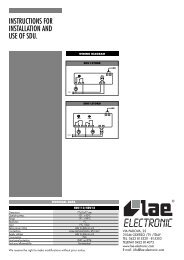
12…24Vac ±10% 50Hz/60Hz<br />
12…35Vdc<br />
N.B.: per versione “T” con seriale solo 12…35Vdc<br />
33.2 Alimentazione da rete a 24/115/230 Vac<br />
Modelli: <strong>ATR121</strong>-AB o C e <strong>ATR141</strong>-AB o C<br />
24Vac ±10% 50/60Hz<br />
230Vac ±10% 50/60Hz<br />
115Vac ±10% 50/60Hz<br />
33.3 Ingresso analogico per sonde in temperatura<br />
Per termocoppia K, S, R, J;<br />
Rispettare le polarità<br />
Per eventuali prolunghe utilizzare cavo e morsetti<br />
compensati adatti alla termocoppia utilizzata.<br />
Pt 100 3 Fili<br />
(solo per modelli AD)<br />
Per un corretto funzionamento dello strumento,<br />
utilizzare sonde isolate da terra.<br />
In caso contrario, utilizzare singolo trasformatore isolato<br />
per ogni strumento.<br />
Per termoresistenza Pt100 a tre fili,<br />
Per il collegamento a tre fili usare cavi della stessa<br />
sezione.<br />
Per Pt100 a due fili cortocircuitare morsetti 10 e 12.<br />
12<br />
11<br />
10<br />
Normalmente, su Pt100, A e C sono dello stesso colore.<br />
Per : PTC 1000 Ω<br />
NTC 10 KΩ<br />
PT500, PT1000<br />
Potenziometri Lineari 6K o 150K F.S.<br />
33.4 Ingresso analogico normalizzato<br />
Per segnali normalizzati in tensione<br />
0…10V<br />
Rispettare le polarità<br />
Ri>=110KΩ<br />
Per segnali normalizzati in corrente 0 ÷ 20mA oppure<br />
4 ÷ 20mA con sensori a tre fili. Rispettare le polarità<br />
39