REGOLATORE CONTROLLER ATR121 ATR141 Manuale User ...
REGOLATORE CONTROLLER ATR121 ATR141 Manuale User ...
REGOLATORE CONTROLLER ATR121 ATR141 Manuale User ...

Create successful ePaper yourself
Turn your PDF publications into a flip-book with our unique Google optimized e-Paper software.
<strong>REGOLATORE</strong><br />
<strong>CONTROLLER</strong><br />
<strong>ATR121</strong><br />
<strong>ATR141</strong><br />
<strong>Manuale</strong><br />
<strong>User</strong> Manual
Contents<br />
1 SECTION FOR USERS....................................................................................................4<br />
2 DISPLAYS AND KEYS .....................................................................................................4<br />
3 CHANGE OF SETPOINT VALUE.....................................................................................5<br />
4 LIST OF ERROR MESSAGES .........................................................................................5<br />
5 SECTION FOR INSTALLERS ..........................................................................................6<br />
6 INTRODUCTION ..............................................................................................................6<br />
7 ORDERING CODES.........................................................................................................6<br />
8 TECHNICAL DATA...........................................................................................................7<br />
8.1 Sizes and installation ...............................................................................................8<br />
9 ELECTRICAL WIRINGS...................................................................................................9<br />
10 WIRING DIAGRAM <strong>ATR121</strong> / <strong>ATR141</strong>........................................................................9<br />
10.1 Low tension power supply 12/24 Vac-Vdc Models: <strong>ATR121</strong>-AD , <strong>ATR141</strong>-AD ....9<br />
10.2 Power supply 24/115/230 Vac Models: <strong>ATR121</strong>-A-B-C , <strong>ATR141</strong>-A-B-C.............9<br />
10.3 Analog input for temperature sensors..................................................................10<br />
10.4 Analog input V / mA .............................................................................................10<br />
10.5 Relay outputs.......................................................................................................11<br />
10.6 SSR output...........................................................................................................11<br />
10.7 Serial communication Models <strong>ATR121</strong>-xT , <strong>ATR141</strong>-xT......................................11<br />
11 OPERATING MODE OF ALARM OUTPUT OUT2 .......................................................12<br />
11.1 Band alarm (setpoint-process).............................................................................12<br />
11.2 Deviation alarm (setpoint-process) ......................................................................12<br />
11.3 Absolute alarm (process).....................................................................................12<br />
12 MODIFY CONFIGURATION PARAMETERS ...............................................................13<br />
13 CONFIGURATION PARAMETERS..............................................................................14<br />
14 TUNING........................................................................................................................19<br />
15 MANUAL START OF TUNING .....................................................................................19<br />
16 AUTOTUNING..............................................................................................................20<br />
17 FUNCTION LATCH ON................................................................................................21<br />
18 FUNCTION NEUTRAL ZONE ......................................................................................23<br />
19 SERIAL COMMUNICATION.........................................................................................24<br />
20 MEMORY CARD ..........................................................................................................28<br />
21 SUPERVISORY SYSTEM WITH <strong>CONTROLLER</strong>S <strong>ATR121</strong> / 141...............................29<br />
22 CONFIGURATION MEMORANDUM............................................................................31<br />
23 NOTES / UPDATE........................................................................................................32<br />
24 SEZIONE UTENTE .....................................................................................................33<br />
25 VISUALIZZATORI E TASTI..........................................................................................33<br />
2
26 CAMBIO DEL SETPOINT ............................................................................................34<br />
27 SEGNALAZIONE ANOMALIE ......................................................................................34<br />
28 SEZIONE INSTALLATORE.........................................................................................35<br />
29 INTRODUZIONE ..........................................................................................................35<br />
30 COMPOSIZIONE DELLA SIGLA..................................................................................35<br />
31 CARATTERISTICHE ....................................................................................................36<br />
31.1 Dimensioni e installazione ...................................................................................37<br />
32 COLLEGAMENTI ELETTRICI ......................................................................................38<br />
33 SCHEMA DI COLLEGAMENTO <strong>ATR121</strong> / <strong>ATR141</strong>...................................................38<br />
33.1 Alimentazione in bassa tensione 12/24 Vac-dc Modelli: <strong>ATR121</strong>-AD e <strong>ATR141</strong>-AD<br />
..................................................................................................................................38<br />
33.2 Alimentazione da rete a 24/115/230 Vac Modelli: <strong>ATR121</strong>-AB o C e <strong>ATR141</strong>-AB o<br />
C ...............................................................................................................................39<br />
33.3 Ingresso analogico per sonde in temperatura .....................................................39<br />
33.4 Ingresso analogico normalizzato .........................................................................39<br />
33.5 Uscite a relè.........................................................................................................40<br />
33.6 Uscita SSR...........................................................................................................40<br />
33.7 Comunicazione seriale Modelli: <strong>ATR121</strong>-xT e <strong>ATR141</strong>-xT..................................40<br />
34 MODI DI INTERVENTO USCITA ALLARME OUT 2 ....................................................41<br />
34.1 Intervento di banda (setpoint-processo) ..............................................................41<br />
34.2 Intervento di deviazione (setpoint-processo) .......................................................41<br />
34.3 Intervento indipendente (processo) .....................................................................41<br />
35 MODIFICA PARAMETRI DI CONFIGURAZIONE ........................................................42<br />
36 TABELLA PARAMETRI DI CONFIGURAZIONE..........................................................43<br />
37 TUNING........................................................................................................................49<br />
38 LANCIO DEL TUNING MANUALE ...............................................................................49<br />
39 TECNICA DI TUNING AUTOMATICO..........................................................................50<br />
40 FUNZIONE LATCH ON................................................................................................51<br />
41 FUNZIONE BANDA MORTA........................................................................................52<br />
42 COMUNICAZIONE SERIALE.......................................................................................53<br />
43 MEMORY CARD ..........................................................................................................57<br />
44 SUPERVISIONE CON <strong>ATR121</strong> / 141 ..........................................................................59<br />
45 PROMEMORIA CONFIGURAZIONE ...........................................................................60<br />
46 NOTE / AGGIORNAMENTI ..........................................................................................61<br />
47 IDENTIFICATION DU MODELE...................................................................................62<br />
48 DONNEES TECHNIQUES ...........................................................................................63<br />
48.1 Dimensions et installation ....................................................................................64<br />
49 RACCORDS ÉLECTRIQUES.......................................................................................65<br />
3
1 SECTION FOR USERS<br />
2 DISPLAYS AND KEYS<br />
Display normally shows<br />
process value (ex. measured temperature),<br />
but can also visualize setpoints or value of<br />
entering data<br />
Visualize set, increase set<br />
or scroll parameters<br />
(whith fast advancement)<br />
OUT 1 OUT 2<br />
L1<br />
<strong>ATR121</strong><br />
FNC<br />
Visualize set, decrease set,<br />
scroll parameters.<br />
(whith fast advancement)<br />
PIXSYS<br />
SET<br />
Visualize setpoints (ex. programmed temperature):<br />
press once for SET1 (Led Out1 flashes),<br />
press twice for SET2 (Led Out2 flashes).<br />
In configuration mode press with arrow<br />
keys to modify value of visualized parameter.<br />
Fleshing when setpoint is visualized<br />
on display and can be modified.<br />
ON when output is active.<br />
<strong>ATR141</strong><br />
OUT 1 OUT 2<br />
L1<br />
FNC<br />
ON when controller responds<br />
to a Master request over<br />
serial line RS485<br />
PIXSYS<br />
SET<br />
Enter configuration of parameters (by password).<br />
Activate special functions.<br />
4
3 CHANGE OF SETPOINT VALUE<br />
To modify the setpoint value, press SET key or one of the arrow-keys: led<br />
OUT1 flashes and it is now possible to enter/modify setpoint value by<br />
pressing the arrow-keys.<br />
1<br />
2<br />
Press Display Do<br />
Display shows main<br />
setpoint; Led<br />
or<br />
OUT1 flashes.<br />
Press or<br />
or<br />
To modify setpoint (fast<br />
advancement available).<br />
SET<br />
SET<br />
Display shows<br />
alarm setpoint and<br />
led OUT2 flashes.<br />
4 LIST OF ERROR MESSAGES<br />
Approx. 4 seconds after last<br />
modify, display shows again<br />
process value (value read by<br />
sensor input).<br />
Press or to<br />
increase or decrease setpoint<br />
value.<br />
When the keys are released,<br />
the new value is automatically<br />
stored and in a few seconds<br />
display shows again process<br />
value.<br />
If the plant does not work properly, the controller stops the running cycle<br />
and shows the anomaly.<br />
For example the controller will notice the failure of a thermocouple<br />
displaying (flashing).<br />
For further error signs check the list below.<br />
Error Cause Do<br />
Programming error EPROM. -<br />
Cold junction failure or room -<br />
temperature out of range<br />
Wrong configuration data. Check configuration<br />
Possible lost of calibration values parameters<br />
5
Open thermocouple or room<br />
temperature out of range<br />
Check sensors connection<br />
and their integrity<br />
5 SECTION FOR INSTALLERS<br />
6 INTRODUCTION<br />
Thanks for choosing a Pixsys Controllers.<br />
Various models with 3-4 digits display make the controller suitable for a<br />
wide range of applications with temperature, humidity, pressure sensors<br />
and linear potentiometers. Output options include both relays and SSR,<br />
but the unit is configurable also as visualizer/indicator for applications not<br />
requiring control or alarm outputs. PID control with Autotuning function<br />
enables to adapt control algorithm to the plant. For applications with linear<br />
potentiometers the function LATCH ON allows a quick calibration.<br />
Memory-card is available to copy configuration parameters and to keep<br />
record of them.<br />
The tables below allow to select easily the required model.<br />
7 ORDERING CODES<br />
Ordering codes model <strong>ATR121</strong><br />
<strong>ATR121</strong>- xx x<br />
Power supply AD 12…24Vac ± 10% 50/60Hz<br />
12…35Vdc<br />
A 24 Vac ± 10% 50/60 Hz<br />
B 230 Vac ± 10% 50/60 Hz<br />
C 115 Vac ± 10% 50/60 Hz<br />
Serial<br />
communication<br />
A<br />
AD<br />
T<br />
T<br />
RS485 - protocoll Modbus RTU slave.<br />
Relay Q2 +alarm function not available in this<br />
model<br />
Only Code AT: 24Vac +/- 10% 50/60 Hz<br />
Only Code ADT: 12…35Vdc<br />
Ordering codes Model <strong>ATR141</strong><br />
<strong>ATR141</strong>- xx x<br />
Power supply AD 12…24Vac ± 10% 50/60Hz<br />
12…35Vdc<br />
A 24 Vac ± 10% 50/60 Hz<br />
B 230 Vac ± 10% 50/60 Hz<br />
C 115 Vac ± 10% 50/60 Hz<br />
6
Serial<br />
communication<br />
A<br />
AD<br />
T<br />
T<br />
RS485 -protocol Modbus RTU slave.<br />
Relay Q2 +alarm function not available in this<br />
model<br />
Only Code AT: 24Vac +/- 10% 50/60 Hz<br />
Only Code ADT: 12…35Vdc<br />
8 TECHNICAL DATA<br />
Main features<br />
Displays 3 digits (0,56 inches) on <strong>ATR121</strong><br />
4 digits (0,40 inches) on <strong>ATR141</strong><br />
+ 3 Leds (Out1 , Out2 , Fnc)<br />
Operating temperature 0-40°C - humidity 35..95uR%<br />
Sealing Front panel IP65 (with gasket) /<br />
Box IP30 / Terminal blocks IP20<br />
Material ABS UL94V2 self- exstinguish<br />
Weight Approx. 100 gr.<br />
Hardware data<br />
Software data<br />
Control algorithm<br />
Data protection<br />
Analog input AN1<br />
Software configurable<br />
Thermocouples K, J, S, R<br />
PT100, NI100, PT500,<br />
PT1000, PTC 1000 ohm ,<br />
NTC 10Kohm<br />
0/4..20mA (Ri=110Kohm)<br />
0…6Kohm<br />
0…150Kohm<br />
7<br />
Tolerance 25°C<br />
0.5 % ± 1 digit for<br />
thermocouples and<br />
RTD<br />
Cold junction<br />
0.2°c/°c of ambient<br />
temperature<br />
0.2% ± 1 digit for V,<br />
mA<br />
Outputs 2 Relays + SSR:<br />
OUT1 :10A resistive on AD codes,<br />
8A resistive with internal transformer<br />
OUT2 : 5A resistive<br />
SSR : 8 Volt 20mA for version A/B/C<br />
15 Volt 30mA for version AD (alim. 12Vac)<br />
30 Volt 30mA for version AD (alim. 24Vac)<br />
On/OFF with hysteresis or P.I.D. with Autotuning<br />
Configuration password, quick programming by<br />
Memory card
8.1 Sizes and installation<br />
OUT 1 OUT 2<br />
PIXSYS<br />
<strong>ATR121</strong><br />
L1<br />
FNC<br />
SET<br />
8
9 ELECTRICAL WIRINGS<br />
Although this controller has been designed to resist the noises in<br />
an industrial environment, please notice the following safety<br />
guidelines:<br />
• Separate control lines from the power wires.<br />
• Avoid the proximity of remote control switches, electromagnetic<br />
meters, powerful engines.<br />
• Avoid the proximity of power groups, especially those with<br />
phase control<br />
10 WIRING DIAGRAM <strong>ATR121</strong> / <strong>ATR141</strong><br />
PIXSYS<br />
M065486-0604<br />
10A 230V<br />
Cosf 1<br />
3A 230V<br />
Cosf 0.8<br />
Q1<br />
5A 230V<br />
Cosf 1<br />
1A 230V<br />
Cosf 0.8<br />
Q2<br />
<strong>ATR121</strong>-AD<br />
2 wire 4/20mA<br />
Power<br />
PT/NI100/1K<br />
PTC/NTC<br />
PIXSYS<br />
M065486-0604<br />
8A 230V<br />
Cosf 1<br />
3A 230V<br />
Cosf 0.8<br />
Q1<br />
5A 230V<br />
Cosf 1<br />
1A 230V<br />
Cosf 0.8<br />
Q2<br />
<strong>ATR141</strong>-B<br />
2 wire 4/20mA<br />
Power<br />
PT/NI100/1K<br />
PTC/NTC<br />
1 2 3 4 5 6 7 8 9 10 11 12<br />
1 2 3 4 5 6 7 8 9 10 11 12<br />
1<br />
Memory<br />
1<br />
Memory<br />
PIXSYS<br />
M065486-0604<br />
8A 230V<br />
Cosf 1<br />
3A 230V<br />
Cosf 0.8<br />
Q1<br />
RS485<br />
<strong>ATR121</strong>-AT<br />
2 wire 4/20mA<br />
Power<br />
PT/NI100/1K<br />
PTC/NTC<br />
1<br />
1 2 3 4 5 6 7 8 9 10 11 12<br />
Memory<br />
10.1 Low tension power supply 12/24 Vac-Vdc<br />
Models: <strong>ATR121</strong>-AD , <strong>ATR141</strong>-AD<br />
12…24Vac ± 10% 50/60Hz<br />
12…35Vdc<br />
**Code “T” with serial communication ONLY<br />
12…35Vdc<br />
10.2 Power supply 24/115/230 Vac<br />
Models: <strong>ATR121</strong>-A-B-C , <strong>ATR141</strong>-A-B-C<br />
9
24Vac ± 10% 50/60Hz<br />
230Vac ± 10% 50/60Hz<br />
115Vac ± 10% 50/60Hz<br />
10.3 Analog input for temperature sensors<br />
Thermocouples K, S, R;J;<br />
Respect polarities<br />
When extending thermocouples be sure to use the<br />
correct extension/compensating cable<br />
Pt 100 3 Wires<br />
Only model AD<br />
To assure optimal operation of the device, use<br />
ground-isolated sensors.<br />
Otherwise use single isolated transformers for<br />
each controller<br />
For a three-wires PT100 use cables with the same<br />
diameter;<br />
For a two-wires Pt100 shortcircuit pins 10 and 12.<br />
3<br />
2<br />
1<br />
For<br />
PTC 1000 ohm<br />
NTC 10 K<br />
PT500, PT1000<br />
Linear potentiometers 6K or 150K<br />
10.4 Analog input V / mA<br />
Signals<br />
0…10V<br />
Respect polarities<br />
Ri>=110KΩ<br />
Signals<br />
0 ÷ 20mA or 4 ÷ 20mA<br />
with three-wires sensors<br />
Respect polarities<br />
A= sensor supply<br />
Check power supply requirements on technical<br />
data sheet of sensor!<br />
Capacity 12…24V / 30mA for models AD<br />
10
Capacity 8V / 20mA for models A-B-C<br />
B= sensor ground<br />
C= sensor output<br />
Signals<br />
0 ÷ 20mA or 4 ÷ 20mA<br />
with sensors requiring external power supply<br />
Respect polarities<br />
B= sensor ground<br />
C= sensor output<br />
Signals<br />
4 ÷ 20mA with two-wires sensors<br />
Respect polarities<br />
A= sensor supply<br />
Check power supply requirements on technical<br />
data sheet of sensor!<br />
Capacity 12…24V / 30mA for models AD<br />
Capacity 8V / 20mA for models A-B-C<br />
C= sensor output<br />
10.5 Relay outputs<br />
10.6 SSR output<br />
• Q1 capacity 8A/250V~ (Models A-B-C) resistive<br />
(manoeuvre 2x10 5 min - 8A/250V~)<br />
• Q1 capacity 10A/250V~ (Model AD) resistive<br />
(manoeuvre 2x10 5 min -10A /250V~)<br />
• Q2 capacity 5A/250V~ resistive (manoeuvre<br />
2x10 5 min a 3A /250V~)<br />
Capacity 12…24V/30mA on model AD<br />
Capacity 8V/20mA on models A-B-C<br />
Command output if configured as SSR<br />
10.7 Serial communication<br />
Models <strong>ATR121</strong>-xT , <strong>ATR141</strong>-xT<br />
RS485, protocol MODBUS-RTU<br />
11
Do not use LT (line termination) resistors<br />
11 OPERATING MODE OF ALARM OUTPUT OUT2<br />
11.1 Band alarm (setpoint-process)<br />
Hysteresis<br />
Comparison value<br />
Hysteresis<br />
Operating mode:<br />
• active outside band<br />
• active inside band<br />
Example : outside<br />
Time<br />
11.2 Deviation alarm (setpoint-process)<br />
Hysteresis<br />
Comparison value<br />
Operating mode:<br />
• deviation high<br />
• deviation low<br />
Example: deviation high.<br />
Time<br />
11.3 Absolute alarm (process)<br />
12
Comparison value<br />
Hysteresis<br />
Operating mode:<br />
• active over<br />
• active below<br />
Example: active below<br />
Time<br />
Comparison value<br />
Hysteresis<br />
Programming Par.<br />
Delay<br />
Delay<br />
Positive<br />
Negative<br />
12 MODIFY CONFIGURATION PARAMETERS<br />
The configuration menu of the unit is password protected to prevent<br />
unauthorised access to the instrument set up.<br />
1<br />
2<br />
Press Display Do<br />
After 5 seconds display<br />
FNC<br />
shows , first digit on<br />
the left is flashing.<br />
on <strong>ATR141</strong><br />
Increase first digit to “1”.<br />
SET<br />
Press to reach<br />
following digit and enter<br />
configuration password<br />
“123” for <strong>ATR121</strong><br />
or “1234” for <strong>ATR141</strong><br />
13
3<br />
SET<br />
Display shows first<br />
configuration parameter<br />
for <strong>ATR121</strong><br />
4<br />
for <strong>ATR141</strong><br />
The arrow-keys allow the<br />
movement through the<br />
configuration table in both<br />
forward and backward<br />
directions.<br />
Select parameter to<br />
SET<br />
modify, press to<br />
visualize it and use arrow<br />
keys to modify value.<br />
13 CONFIGURATION PARAMETERS<br />
P Display Description<br />
1 <strong>ATR121</strong><br />
<strong>ATR141</strong><br />
Select type of<br />
control output<br />
2 Select type of<br />
connected<br />
sensor<br />
only for<br />
AD models :<br />
Range<br />
<strong>ATR121</strong> <strong>ATR141</strong> Description<br />
Control Q1<br />
Alarm Q2<br />
Control Q1<br />
Alarm SSR<br />
Control SSR<br />
Alarm Q1<br />
TC type K<br />
-260…1360<br />
TC type S<br />
-40…1760<br />
TC type R<br />
-40…1760<br />
TC type J<br />
-200…1200<br />
14
To assure<br />
optimal working<br />
of the unit, use<br />
ground-isolated<br />
sensors.<br />
Otherwise use<br />
single isolated<br />
transformers for<br />
each controller.<br />
3 Select position<br />
decimal point<br />
4 Lower limit<br />
setpoint<br />
5 Upper limit<br />
setpoint<br />
6 Lower limit<br />
signals V/mA<br />
7 Upper limit<br />
signals V/mA<br />
8<br />
Function<br />
<strong>ATR121</strong> Latch On<br />
(Automatic<br />
setting of limits<br />
Pt100 (-100..600°C)<br />
Pt100 (-100..140°C)<br />
Ni100 (-60..180°C)<br />
Ntc 10KΩ<br />
-40…125<br />
Ptc 1KΩ<br />
-50…150<br />
Pt500<br />
-100…600<br />
Pt1000<br />
-100…600<br />
0…10V<br />
0…20mA<br />
4…20mA<br />
Pot. 6KΩ<br />
Max 6KΩ<br />
Pot. 150KΩ<br />
Max 150KΩ<br />
no decimal point<br />
1 decimal point<br />
2 decimal points<br />
----------- 3 decimal points<br />
-199..<br />
+999 digit<br />
-199…<br />
+999 digit<br />
-199…<br />
+999 digit<br />
-199…<br />
+999 digit<br />
-999..<br />
+9999 digit<br />
-999…<br />
+9999 digit<br />
-999…<br />
+9999 digit<br />
-999…<br />
+9999 digit<br />
Degrees for<br />
temperature sensor<br />
digits for linear signals<br />
and potentiometers<br />
Degrees for<br />
temperature sensor.<br />
Digits for linear<br />
signals and<br />
potentiometers<br />
disabled<br />
Standard<br />
15
<strong>ATR141</strong><br />
for linear<br />
potentiometers)<br />
virtual zero stored<br />
virtual zero at start<br />
9<br />
Offset<br />
<strong>ATR121</strong> calibration.<br />
This value is<br />
added to the<br />
process value<br />
<strong>ATR141</strong><br />
visualized on<br />
display (usually<br />
correcting the<br />
ambient<br />
temperature)<br />
10<br />
Gain calibration<br />
<strong>ATR121</strong> of sensor input<br />
(The visualized<br />
number is<br />
multiplied for<br />
<strong>ATR141</strong><br />
this % value to<br />
calibrate<br />
process value)<br />
11 Type of control<br />
12 Type of contact<br />
for control<br />
output in case<br />
of error<br />
13 <strong>ATR121</strong> State of led<br />
OUT1<br />
<strong>ATR141</strong><br />
according to<br />
relevant contact<br />
14 <strong>ATR121</strong><br />
<strong>ATR141</strong><br />
ON/OFF<br />
hysteresis or<br />
dead band for<br />
P.I.D. control<br />
-19.9…<br />
+99.9 units<br />
-99.9…<br />
+99.9<br />
units<br />
-10.0%…+10.0%<br />
-199…<br />
+999 digits<br />
-999…<br />
+999 digits<br />
Tenth of degree for<br />
temperature. Digits for<br />
linear signals and<br />
potentiometers<br />
Heating (N.O.)<br />
Cooling (N.C.)<br />
Open contact safety<br />
Closed contact safety<br />
On with open contact<br />
On with closed<br />
contact<br />
Tenth of degree for<br />
temperature sensor.<br />
Digits for linear<br />
signals and<br />
potentiometers<br />
16
15 Proportional<br />
band<br />
Width of the<br />
process<br />
expressed as<br />
units (°C if<br />
temperature)<br />
16 Integral time.<br />
Inertia of the<br />
process<br />
expressed as<br />
seconds<br />
17 Derivative time<br />
for P.I.D.<br />
Usually ¼ of<br />
integral time<br />
18 Cycle time for<br />
timeproportioning<br />
output (usually<br />
over 10s for<br />
contactors, 1s<br />
for SSR)<br />
19 Select<br />
operating of<br />
alarm.<br />
Setpoint for<br />
alarm is SET2.<br />
20 State of contact<br />
for alarm output<br />
and type of<br />
operating<br />
0…999 0…9999 0 = On/Off<br />
°C (temp.)<br />
digit (V/mA)<br />
0-999 0-9999 seconds<br />
(0 excludes Integral)<br />
0…999 0…9999 seconds<br />
(0 excludesDerivative)<br />
1-300 seconds<br />
absolute related to<br />
process<br />
band alarm<br />
Deviation high<br />
Deviation low<br />
absolute related to<br />
setpoint 1<br />
Normally open, active<br />
at Start<br />
Normally closed,<br />
active at Start<br />
Normally open, active<br />
at alarm setpoint 1 .<br />
Normally closed,<br />
active at alarm<br />
setpoint 1<br />
1 At starting the output is desabled in case of any alarm condition. After the alarm has<br />
been solved, output will be activated only if alarm condition should occur again.<br />
17
21 State of contact<br />
for alarm output<br />
in case of error<br />
Open contact safety<br />
Closed contact safety<br />
22 <strong>ATR121</strong><br />
<strong>ATR141</strong><br />
State of led<br />
OUT2<br />
according to<br />
relevant contact<br />
ON with open contact<br />
ON with closed<br />
contact<br />
23 <strong>ATR121</strong><br />
<strong>ATR141</strong><br />
24 <strong>ATR121</strong><br />
<strong>ATR141</strong><br />
Alarms<br />
hysteresis<br />
25 Setpoint<br />
protection.<br />
Select options<br />
available to the<br />
operator<br />
26 <strong>ATR121</strong><br />
<strong>ATR141</strong><br />
-199…<br />
+999 digits<br />
-999…<br />
+9999<br />
digits<br />
Tenth of degree for<br />
temperature sensor.<br />
Digits for linear<br />
signals and<br />
potentiometers<br />
Alarm delay -180…+180 seconds<br />
Negative: delay at<br />
alarm deactivation<br />
Positive: delay at<br />
alarm activation<br />
Access free to all<br />
setpoints<br />
Control setpoint<br />
protected<br />
Alarm setpoint<br />
protected<br />
Access denied to all<br />
setpoints<br />
Software filter 1-15 Number of averages<br />
(Sampling frequency<br />
15Hz)<br />
27 <strong>ATR121</strong><br />
<strong>ATR141</strong><br />
Select type of<br />
auto-tuning<br />
desabled<br />
automatic<br />
manual start of Tuning<br />
28 <strong>ATR121</strong><br />
<strong>ATR141</strong><br />
Select type of<br />
operating<br />
Double setpoint<br />
Single setpoint<br />
Visualizer only<br />
29 <strong>ATR121</strong> Type of degree Celsius<br />
function Neutral zone<br />
18
Fahrenheit<br />
<strong>ATR141</strong><br />
30 <strong>ATR121</strong><br />
<strong>ATR141</strong><br />
31 <strong>ATR121</strong><br />
Baud rate of<br />
serial<br />
communication<br />
Slave address 1-254<br />
300 bit/s<br />
9600 bit/s<br />
19200 bit/s<br />
38400 bit/s<br />
<strong>ATR141</strong><br />
32 <strong>ATR121</strong><br />
<strong>ATR141</strong><br />
Delay serial<br />
communication<br />
0-100 Milliseconds<br />
14 TUNING<br />
Tuning operation allows the setting of optimal PID parameters in order to<br />
assure good control action:<br />
-Stable, “straight-line” control of temperature around setpoint, without<br />
fluctuations;<br />
-quick response to deviations from setpoint caused by external noises<br />
Tuning involves calculating and setting of the following parameters:<br />
• Proportional band (inertia of plant; expressed as °C for temperature)<br />
• Integral time (determines the time taken by the controller to remove<br />
steady-state error signals, Inertia of plant expresses as time value);<br />
• Derivative time (reaction of controller to change of measured value,<br />
usually ¼ of integral time)<br />
Setpoint value cannot be modified during Autotuning.<br />
15 MANUAL START OF TUNING<br />
Select parameter as (manual start)<br />
Press Display Do<br />
19
1<br />
FNC<br />
Display shows<br />
2<br />
Display shows<br />
3<br />
FNC<br />
or<br />
wait for 4<br />
seconds.<br />
Display will show process<br />
value and<br />
alternately until the function<br />
is completed (it may take a<br />
few minutes).<br />
To interrupt the function<br />
press<br />
FNC<br />
and press<br />
to select .<br />
16 AUTOTUNING<br />
Parameter must be selected as . Autotuning starts<br />
automatically when the controller is switched-on or when setpoint value<br />
20
has been modified. Display alternates between process value and the<br />
writing until the function has been completed (it may take a few<br />
minutes).<br />
To interrupt the function, press<br />
FNC<br />
and press to select .<br />
17 FUNCTION LATCH ON<br />
For application with linear potentiometers<br />
(potentiometer up to<br />
6K) and (potentiometer up to 150K) or 0…10Volt , 0/4…20mA<br />
inputs, the lower limit of scale (see parameter ) can be set to<br />
minimum position of sensor; it is also possible to set the upper limit of<br />
scale (parameter<br />
be done directly on site.<br />
) to the max. position of sensor and this can<br />
The option “virtual zero” (selecting or ) allows also to fix<br />
the point where the controller will read zero (but still keeping the range of<br />
scale between and .<br />
Selecting<br />
virtual zero must be reprogrammed at each starting of<br />
the controller; selecting virtual zero will be stored after first<br />
calibration.<br />
To enable function LATCH ON, select chosen configuration for parameter<br />
2 . For calibration function follow the table below.<br />
Press Display Do<br />
2 Calibration function leaves configuration mode after that the relevant<br />
parameter has been modified.<br />
21
1<br />
2<br />
3<br />
4<br />
FNC<br />
SET<br />
Leave configuration mode.<br />
Display shows cycling process<br />
value and writing .<br />
Store minimum value.<br />
Display shows<br />
Store max. value<br />
Display shows<br />
Store virtual zero.<br />
Display shows<br />
** If is selected, at<br />
starting repeat calibration on<br />
point 4.<br />
Set the sensor on minimum<br />
operating value<br />
(corresponding to )<br />
Set the sensor on max.<br />
operating value<br />
(corresponding to )<br />
To quit standard proceeding<br />
FNC<br />
press .<br />
To enter “virtual zero” set the<br />
sensor to zero point.<br />
To interrupt the function<br />
press<br />
FNC<br />
.<br />
MAX<br />
MIN<br />
ZERO<br />
22
18 FUNCTION NEUTRAL ZONE<br />
The Neutral Zone function (which can be enabled selecting<br />
parameter 28<br />
) allows the setting of a neutral zone control action<br />
as described in the graph. In Heating mode (parameter<br />
on<br />
selected<br />
as ), the operating treshold for control relay will be the value<br />
resulting from SET1 minus SET2, and the operating treshold for alarm<br />
relay will be SET1 plus SET2 (hysteresis is always set via parameter<br />
). Within this band both relays are off; one relay works above this<br />
band and one relay works below.<br />
In Cooling mode (parameter selected as ) the operating<br />
tresholds of both relays are reversed.<br />
TEMPERATURE<br />
Operating Zone<br />
alarm Relay<br />
PROCESS<br />
Hysteresis (HY.C)<br />
SET 1<br />
SET 2<br />
SET 2<br />
Hysteresis (HY.C)<br />
Operating Zone<br />
comand Relay<br />
Operating Zone<br />
Comand Relay<br />
Ex. Function neutral zone for heating modality (HEA/HEAT on parameter REG)<br />
Standard alarm (band, deviation …) is not available in this mode.<br />
TIME<br />
23
19 SERIAL COMMUNICATION<br />
Serial communication RS485 and protocol MODBUS – RTU enable the<br />
controller <strong>ATR121</strong>/141 to receive and exchange data, allowing the<br />
connection of more units to a centralized supervisory system. The device<br />
can be configured only as Slave unit.<br />
LT (line termination) resistors on RS485 line must be removed to avoid<br />
anomalies.<br />
Each controller will respond to a request only if it contains the same<br />
address which is written on parameter . The range of admitted<br />
addresses is 1 – 254. Address 255 is used to communicate with all the<br />
connected units (Broadcast modality). Single units <strong>ATR121</strong>/141 on the<br />
same line cannot have the same address. Selecting 0 all connected units<br />
receive request but no answer is required. <strong>ATR121</strong>/141 may delay the<br />
answer to request. This delay (expressed as milliseconds) must be<br />
entered on parameter<br />
After each parameters change, the controller stores the new values on<br />
EEPROM memory ( 100000 writing). Modified sepoint values are stored<br />
on EEPROM memory with 10 seconds delay.<br />
** Any operation on words which are not listed in the table below may<br />
cause anomalies or malfunction.<br />
Baud-rate Selectable by parameter<br />
MD.1 = 300bit/s<br />
MD.2 = 9600bit/s<br />
MD.3 = 19200bit/s<br />
MD.4 = 38400bit/s<br />
Format 8, N, 1 (8bit, no parity, 1 stop)<br />
Supported functions WORD READING (max 20 word) (0x03, 0x04)<br />
SINGLE WORD WRITING (0x06)<br />
MULTIPLE WORDS WRITING (0x10)<br />
24
MODBUS<br />
ADDRESS<br />
DESCRIPTION<br />
READ/<br />
WRITE<br />
RESET<br />
VALUE<br />
0 Type of device R 101/102<br />
1 Software version R <br />
2 Reserved R <br />
3 Reserved R <br />
4 Reserved R 0<br />
5 Slave Address R EEPR<br />
6 Reserved R <br />
60 Type of calibration R/W 0<br />
61 Calibration action R/W 0<br />
62 Calibration value R/W 0<br />
63 Calibration Password R/W 0<br />
64 Calibration completed R EEPR<br />
65 State of relays during calibration R/W 0<br />
300 Calibration 0mV TC R EEPR<br />
301 Calibration 40mV TC R EEPR<br />
302 Calibration 100Ω PT100 (-100..600°C) R EEPR<br />
303 Calibration 300Ω PT100 (-100..600°C) R EEPR<br />
304 Calibration 100Ω comp. PT100 (-100..600°C) R EEPR<br />
305 Calibration 300Ω comp. PT100 (-100..600°C) R EEPR<br />
306 Calibration 100Ω PT100 (-100..140°C) R EEPR<br />
307 Calibration 138.5Ω PT100 (-100..140°C) R EEPR<br />
308 Calibration 100Ω comp. PT100 (-100..140°C) R EEPR<br />
309 Calibration 138.5Ω comp. PT100(-<br />
R EEPR<br />
100..140°C)<br />
310 Calibration 0V sensor 0-10V R EEPR<br />
311 Calibration 10V sensor 0-10V R EEPR<br />
312 Calibration 0mA sensor 0/4-20mA R EEPR<br />
313 Calibration 20mA sensor 0/4-20mA R EEPR<br />
314 Calibration 10KΩ NTC R EEPR<br />
315 Calibration 1KΩ PTC or PT1000 R EEPR<br />
316 Calibration ambient temperature (OFFSET) R EEPR<br />
317 Calibration ambient temperature (mV diode L) R EEPR<br />
318 Calibration ambient temperature (mV diode H) R EEPR<br />
25
319 Calibrations Flags completed R EEPR<br />
400 Setpoint 1 R EEPR<br />
401 Setpoint 2 R EEPR<br />
402 Lower value Latch-on H R EEPR<br />
403 Lower value Latch-on L R EEPR<br />
404 Upper value Latch-on H R EEPR<br />
405 Upper value Latch-on L R EEPR<br />
406 Value Virtual zero Latch-on R EEPR<br />
407 Control Flags Latch-on R EEPR<br />
408 Reserved R EEPR<br />
409 Reserved R EEPR<br />
1000 Process value R 0<br />
1001 Cold junction value R 0<br />
1002 Value Setpoint 1 R/W EEPR<br />
1003 Value Setpoint 2 R/W EEPR<br />
1004 Percentage control output R 0<br />
2001<br />
Parameter 1<br />
R/W EEPR<br />
2002<br />
Parameter 2<br />
R/W EEPR<br />
2003<br />
Parameter 3<br />
R/W EEPR<br />
2004<br />
Parameter 4<br />
R/W EEPR<br />
2005<br />
Parameter 5<br />
R/W EEPR<br />
2006<br />
Parameter 6<br />
R/W EEPR<br />
2007<br />
Parameter 7<br />
R/W EEPR<br />
2008<br />
Parameter 8<br />
R/W EEPR<br />
2009<br />
Parameter 9<br />
R/W EEPR<br />
2010<br />
Parameter 10<br />
R/W EEPR<br />
2011<br />
Parameter 11<br />
R/W EEPR<br />
2012<br />
Parameter 12<br />
R/W EEPR<br />
2013<br />
Parameter 13<br />
R/W EEPR<br />
2014<br />
Parameter 14<br />
R/W EEPR<br />
2015<br />
Parameter 15<br />
R/W EEPR<br />
26
2016<br />
2017<br />
2018<br />
2019<br />
2020<br />
2021<br />
2022<br />
2023<br />
2024<br />
2025<br />
2026<br />
2027<br />
2028<br />
2029<br />
2030<br />
2031<br />
2032<br />
Parameter 16<br />
Parameter 17<br />
Parameter 18<br />
Parameter 19<br />
Parameter 20<br />
Parameter 21<br />
Parameter 22<br />
Parameter 23<br />
Parameter 24<br />
Parameter 25<br />
Parameter 26<br />
Parameter 27<br />
Parameter 28<br />
Parameter 29<br />
Parameter 30<br />
Parameter 31<br />
Parameter 32<br />
R/W<br />
R/W<br />
R/W<br />
R/W<br />
R/W<br />
R/W<br />
R/W<br />
R/W<br />
R/W<br />
R/W<br />
R/W<br />
R/W<br />
R/W<br />
R/W<br />
R/W<br />
R/W<br />
R/W<br />
EEPR<br />
EEPR<br />
EEPR<br />
EEPR<br />
EEPR<br />
EEPR<br />
EEPR<br />
EEPR<br />
EEPR<br />
EEPR<br />
EEPR<br />
EEPR<br />
EEPR<br />
EEPR<br />
EEPR<br />
EEPR<br />
EEPR<br />
27
20 MEMORY CARD<br />
Parameters and setpoint values can be easily copied from one controller<br />
to others using the MEMORY CARD. The controller must be switchedoff<br />
before entering the Card. Check also entry direction (components<br />
must be turned towards front panel).<br />
Switching-on the controller, display will show<br />
3 .<br />
1<br />
2<br />
Press Display Do<br />
FNC<br />
shows ,<br />
shows .<br />
The controller stores value<br />
and restarts.<br />
Select (Memo<br />
load) to store values of<br />
Memory on the controller.<br />
Select to keep<br />
values of the controller<br />
unchanged.<br />
Updating values of memory card<br />
To update values of Memory card follow<br />
the above proceedings, selecting<br />
on display, so values of memory will not<br />
be stored on the controller 4 . Enter<br />
configuration mode, modify at least one<br />
parameter and exit.<br />
3 Only if values stored on Memory Card are correct.<br />
4 If the controller does not visualize at starting, this means that no<br />
values are stored on Memory Card, but they may be copied and updated.<br />
28
21 SUPERVISORY SYSTEM WITH <strong>CONTROLLER</strong>S <strong>ATR121</strong> / 141<br />
Below main elements of the system. Consider the converter<br />
RS232/RS485 with automatic direction and the suggested serial<br />
communication cables.<br />
29
Sensor : PT100<br />
PT/NI100/1K<br />
PTC/NTC<br />
6 7 8 9 10 11 12<br />
RS485<br />
PT/NI100/1K<br />
PTC/NTC<br />
6 7 8 9 10 11 12<br />
RS485<br />
PT/NI100/1K<br />
PTC/NTC<br />
6 7 8 9 10 11 12<br />
RS485<br />
Controller SLAVE 1<br />
Mod. : <strong>ATR121</strong>-AT<br />
Controller SLAVE 2<br />
Mod. : <strong>ATR121</strong>-AT<br />
Controller SLAVE 254<br />
Mod. : <strong>ATR121</strong>-AT<br />
PERSONAL COMPUTER<br />
Serial line<br />
RS 485<br />
Serial line<br />
RS 232<br />
Converter Rs232 / Rs485<br />
Automatic direction<br />
Mod. : PIX-RECORDER<br />
Use shielded cable<br />
1 twisted pair.<br />
According to EIA RS-485.<br />
Suggested cable: Belden 9841.<br />
AN-0020-3704<br />
30
22 CONFIGURATION MEMORANDUM<br />
Date:<br />
Model <strong>ATR121</strong>/141:<br />
Installer:<br />
Plant:<br />
Notes:<br />
Par. Description Default Prom.<br />
Select type of command output<br />
Sensor Type<br />
Visualization of decimal point<br />
Lower limit of setpoint 0<br />
Upper limit of setpoint<br />
31<br />
<strong>ATR121</strong><br />
<strong>ATR141</strong><br />
999<br />
1750<br />
Lower limit only for V/I V/mA 0<br />
Upper limit only for V/I V/mA 999<br />
Latch On Function<br />
Offset calibration 0.0<br />
Gain calibration 0<br />
Type of action<br />
Type of contact for control output in<br />
case of anomaly<br />
Select state of OUT1<br />
Hysteresis dead/band 0<br />
Proportional band 0<br />
Integral time 0<br />
Derivative time 0<br />
Proportional cycle time 10<br />
Type of alarm<br />
Contact alarm OUT<br />
State of contact for alarm output in case<br />
of anomaly<br />
State of the LED<br />
Alarms hysteresis 0
delay alarm 0<br />
Set protection.<br />
Software filter 10<br />
Type of autotuning<br />
Type of operating<br />
Degrees selection<br />
Baud rate<br />
address slave 254<br />
Serial delay 20<br />
23 NOTES / UPDATE<br />
32
24 SEZIONE UTENTE<br />
25 VISUALIZZATORI E TASTI<br />
Visualizza normalmente<br />
il processo (es.: Temperatura sonda),<br />
ma può visualizzare anche il valore<br />
dei setpoint (punti d’intervento)<br />
oppure i dati in inserimento.<br />
Visualizza il set, incrementa<br />
il set o scorre i parametri<br />
(con avanzamento veloce).<br />
OUT 1 OUT 2<br />
L1<br />
<strong>ATR121</strong><br />
FNC<br />
Visualizza il set, decrementa<br />
il set o scorre i parametri.<br />
(Con avanzamento veloce)<br />
PIXSYS<br />
SET<br />
Visualizza i setpoint (ex.:temperatura impostata):<br />
una pressione Set1(Led Out1 lampeggia) ,<br />
seconda pressione Set2 (Led Out2 Lampeggia).<br />
In Configurazione se premuto contemporaneamente<br />
ad uno dei tasti freccia permette di<br />
modificare il valore del parametro visualizzato.<br />
Quando lampeggiano stanno ad indicare il setpoint visualizzato<br />
sul display e quindi la possibilità di variarlo con i tasti freccia.<br />
Quando accesi fissi indicano l’uscita attiva.<br />
<strong>ATR141</strong><br />
OUT 1 OUT 2<br />
L1<br />
FNC<br />
Si accende quando il regolatore<br />
risponde ad un’interrogazione da<br />
Seriale (versione con RS485).<br />
PIXSYS<br />
SET<br />
Accesso alla programmazione dei parametri(sotto password).<br />
Attiva le funzioni speciali<br />
33
26 CAMBIO DEL SETPOINT<br />
Per modificare il valore impostato premere il tasto una volta, o<br />
premere uno dei tasti freccia; il led OUT1 lampeggia, è quindi possibile<br />
impostare un nuovo valore con le frecce.<br />
Premere Effetto Eseguire<br />
Il display<br />
1<br />
visualizza il<br />
oppure<br />
setpoint di Premere uno dei tasti ,<br />
comando e il Led per modificare il valore di setpoint (con<br />
OUT1 lampeggia. avanzamento veloce). Dopo circa 4<br />
secondi dall’ultima modifica il display torna<br />
oppure<br />
a visualizzare il processo (ingresso sonda).<br />
2<br />
SET<br />
SET<br />
Il display<br />
visualizza il<br />
setpoint di<br />
allarme e il Led<br />
OUT2 lampeggia.<br />
27 SEGNALAZIONE ANOMALIE<br />
34<br />
SET<br />
Premere o per aumentare o<br />
diminuire il valore di setpoint desiderato.<br />
Al rilascio dei tasti dopo circa 4 secondi il<br />
nuovo valore viene registrato<br />
automaticamente, il display torna a<br />
visualizzare il processo<br />
In caso di mal funzionamento dell’impianto, il regolatore attiva i relè, come<br />
da parametri 12 e 21 e segnala il tipo di anomalia riscontrata. Per<br />
esempio il regolatore segnalerà la rottura di una eventuale termocoppia<br />
collegata visualizzando (lampeggiante) sul display.<br />
Per le segnalazioni vedere la tabella:<br />
Errore Causa Cosa Fare<br />
Errore in programmazione cella EPROM. -<br />
Guasto sensore temperatura giunto -<br />
freddo o temperatura ambiente al di<br />
fuori dei limiti ammessi.<br />
Dati di configurazione errati. Possibile<br />
perdita della tarature dello strumento.<br />
Verificare che i parametri di<br />
configurazione siano corretti.
Termocoppia aperta o temperatura<br />
fuori limite.<br />
Controllare il collegamento<br />
con le sonde e la loro<br />
integrità.<br />
28 SEZIONE INSTALLATORE<br />
29 INTRODUZIONE<br />
Grazie per aver scelto un regolatore Pixsys.<br />
Le versioni con display a tre e quattro digits permettono di impiegare lo strumento<br />
in una vasta gamma di applicazioni, ad esempio con sensori di temperatura,<br />
umidità, pressione, livello o potenziometri lineari. Le soluzioni di uscita prevedono<br />
sia il relè che la logica per SSR, è comunque configurabile il solo funzionamento<br />
come visualizzatore per gli impianti che non necessitano di uscite comando o di<br />
allarme. Con il PID e l’Autotune è semplice adattare all’impianto l’algoritmo di<br />
regolazione migliore, mentre nel caso di funzionamento con potenziometri lineari<br />
la funzione LATCH ON velocizza la taratura della macchina.<br />
Come sulla più recente strumentazione Pixsys sono disponibili Memory-card per<br />
la configurazione in serie e per lo storico degli impianti.<br />
Seguendo le tabelle sottostante si può facilmente identificare il modello<br />
desiderato.<br />
30 COMPOSIZIONE DELLA SIGLA<br />
Composizione della sigla Modello <strong>ATR121</strong><br />
<strong>ATR121</strong>- xx x<br />
Alimentazione AD 12…24Vac ±10% 50/60Hz<br />
12…35Vdc<br />
A 24 Vac ±10% 50/60 Hz<br />
B 230 Vac ±10% 50/60 Hz<br />
C 115 Vac ±10% 50/60 Hz<br />
Seriale A T Rs485 con protocollo Modbus RTU slave.<br />
AD T In questa versione non è disponibile il Relè Q2 e la<br />
funzione allarme è inibita.<br />
Solo versione AT: 24Vac ±10% 50/60 Hz<br />
Solo versione ADT: 12…35Vdc<br />
Composizione della sigla Modello <strong>ATR141</strong><br />
<strong>ATR141</strong>- xx x<br />
Alimentazione<br />
AD<br />
A<br />
B<br />
C<br />
12…24Vac ±10% 50/60Hz<br />
12…35Vdc<br />
24 Vac ±10% 50/60 Hz<br />
230 Vac ±10% 50/60 Hz<br />
115 Vac ±10% 50/60 Hz<br />
35
Seriale A<br />
AD<br />
T<br />
T<br />
31 CARATTERISTICHE<br />
Rs485 con protocollo Modbus RTU slave.<br />
In questa versione non è disponibile il Relè Q2 e la<br />
funzione allarme è inibita.<br />
Solo versione AT: 24Vac ±10% 50/60 Hz<br />
Solo versione ADT: 12…35Vdc<br />
Caratteristiche generali<br />
Display 3 display (0,56 pollici) su <strong>ATR121</strong><br />
4 display (0,40 pollici) su <strong>ATR141</strong><br />
+ 3 led (Out1 , Out2 , Fnc)<br />
Temperatura di esercizio 0-40°C - umidità 35..95uR%<br />
Protezione Pannello frontale IP65 (con guarnizione) /<br />
Contenitore IP30 / Morsettiere IP20<br />
Materiale Policarbonato UL94V0 autoestinguente<br />
Peso ca. 100 g.<br />
Caratteristiche hardware<br />
Ingressi analogici AN1<br />
configurabile via software<br />
Termocoppie : K, S, R, J<br />
Termoresistenze: PT100,<br />
NI100, PT500, PT1000,<br />
PTC 1000 ohm ,<br />
NTC 10Kohm<br />
Segnali:<br />
0/4..20mA (Ri=110Kohm)<br />
0…6Kohm<br />
0…150Kohm<br />
Tolleranze a 25°C<br />
0.5 % ± 1 digit x<br />
termocoppie e<br />
termoresistenze<br />
Giunto freddo<br />
0.2°c/°c di<br />
temperatura<br />
ambiente<br />
0.2% ± 1 digit per<br />
V/I<br />
Uscite 2 Rele’ + SSR:<br />
OUT1: 10A carico resistivo su versione AD , 8A<br />
carico resistivo su versioni con trasformatore.<br />
OUT2: 5A carico resistivo.<br />
SSR:8 Volt 20mA per versioni A/B/C.<br />
15Volt 30mA per versioni AD(alim. 12Vac)<br />
30Volt 30mA per versioni AD(alim. 24Vac)<br />
Caratteristiche software<br />
Algoritmo di On/OFF con isteresi o P.I.D. con Autotune<br />
regolazione<br />
36
Protezione dati Parametri sotto password programmazione veloce da<br />
memory-card<br />
31.1 Dimensioni e installazione<br />
OUT 1 OUT 2<br />
PIXSYS<br />
<strong>ATR121</strong><br />
L1<br />
FNC<br />
SET<br />
37
32 COLLEGAMENTI ELETTRICI<br />
Benché questo regolatore sia stato progettato per resistere ai più<br />
gravosi disturbi presenti in ambienti industriali, è buona norma<br />
seguire le seguenti precauzioni:<br />
Distinguere la linea d’alimentazione da quelle di potenza.<br />
Evitare la vicinanza di gruppi di teleruttori, contattori<br />
elettromagnetici, motori di grossa potenza.<br />
Evitare la vicinanza di gruppi di potenza, in particolare se a<br />
controllo di fase.<br />
33 SCHEMA DI COLLEGAMENTO <strong>ATR121</strong> / <strong>ATR141</strong><br />
PIXSYS<br />
M065486-0604<br />
10A 230V<br />
Cosf 1<br />
3A 230V<br />
Cosf 0.8<br />
Q1<br />
5A 230V<br />
Cosf 1<br />
1A 230V<br />
Cosf 0.8<br />
Q2<br />
<strong>ATR121</strong>-AD<br />
2 wire 4/20mA<br />
Power<br />
PT/NI100/1K<br />
PTC/NTC<br />
PIXSYS<br />
M065486-0604<br />
8A 230V<br />
Cosf 1<br />
3A 230V<br />
Cosf 0.8<br />
Q1<br />
5A 230V<br />
Cosf 1<br />
1A 230V<br />
Cosf 0.8<br />
Q2<br />
<strong>ATR141</strong>-B<br />
2 wire 4/20mA<br />
Power<br />
PT/NI100/1K<br />
PTC/NTC<br />
1 2 3 4 5 6 7 8 9 10 11 12<br />
1 2 3 4 5 6 7 8 9 10 11 12<br />
1<br />
Memory<br />
1<br />
Memory<br />
PIXSYS<br />
M065486-0604<br />
8A 230V<br />
Cosf 1<br />
3A 230V<br />
Cosf 0.8<br />
Q1<br />
RS485<br />
<strong>ATR121</strong>-AT<br />
2 wire 4/20mA<br />
Power<br />
PT/NI100/1K<br />
PTC/NTC<br />
1 2 3 4 5 6 7 8 9 10 11 12<br />
1<br />
Memory<br />
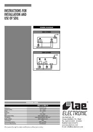
33.1 Alimentazione in bassa tensione 12/24 Vac-dc<br />
Modelli: <strong>ATR121</strong>-AD e <strong>ATR141</strong>-AD<br />
38
12…24Vac ±10% 50Hz/60Hz<br />
12…35Vdc<br />
N.B.: per versione “T” con seriale solo 12…35Vdc<br />
33.2 Alimentazione da rete a 24/115/230 Vac<br />
Modelli: <strong>ATR121</strong>-AB o C e <strong>ATR141</strong>-AB o C<br />
24Vac ±10% 50/60Hz<br />
230Vac ±10% 50/60Hz<br />
115Vac ±10% 50/60Hz<br />
33.3 Ingresso analogico per sonde in temperatura<br />
Per termocoppia K, S, R, J;<br />
Rispettare le polarità<br />
Per eventuali prolunghe utilizzare cavo e morsetti<br />
compensati adatti alla termocoppia utilizzata.<br />
Pt 100 3 Fili<br />
(solo per modelli AD)<br />
Per un corretto funzionamento dello strumento,<br />
utilizzare sonde isolate da terra.<br />
In caso contrario, utilizzare singolo trasformatore isolato<br />
per ogni strumento.<br />
Per termoresistenza Pt100 a tre fili,<br />
Per il collegamento a tre fili usare cavi della stessa<br />
sezione.<br />
Per Pt100 a due fili cortocircuitare morsetti 10 e 12.<br />
12<br />
11<br />
10<br />
Normalmente, su Pt100, A e C sono dello stesso colore.<br />
Per : PTC 1000 Ω<br />
NTC 10 KΩ<br />
PT500, PT1000<br />
Potenziometri Lineari 6K o 150K F.S.<br />
33.4 Ingresso analogico normalizzato<br />
Per segnali normalizzati in tensione<br />
0…10V<br />
Rispettare le polarità<br />
Ri>=110KΩ<br />
Per segnali normalizzati in corrente 0 ÷ 20mA oppure<br />
4 ÷ 20mA con sensori a tre fili. Rispettare le polarità<br />
39
A= alimentazione sensore<br />
Model No. EL101A<br />
Serial No. OL004788<br />
Verificare la compatibilità dell’alimentazione sulla<br />
documentazione del sensore.<br />
Portata 12…24V / 30mA su versioni AD<br />
Portata 8V / 20mA su versioni A-B-C<br />
B= massa sensore<br />
C= uscita sensore<br />
Model No. EL101A<br />
Serial No. OL004788<br />
Per segnali normalizzati in corrente<br />
0 ÷ 20mA oppure 4 ÷ 20mA<br />
con sensori ad alimentazione esterna<br />
Rispettare le polarità<br />
B= massa sensore<br />
C= uscita sensore<br />
Model No. EL101A<br />
Serial No. OL004788<br />
Per segnali normalizzati in corrente<br />
4 ÷ 20mA con sensori a due fili.<br />
Rispettare le polarità<br />
A= alimentazione sensore<br />
Verificare la compatibilità dell’alimentazione sulla<br />
documentazione del sensore.<br />
Portata 12…24V / 30mA su versioni AD<br />
Portata 8V / 20mA su versioni A-B-C<br />
.C= uscita sensore<br />
33.5 Uscite a relè<br />
33.6 Uscita SSR<br />
• Q1 con contatti : 8A/250V~ (Su versioni A-B-C)per<br />
carichi resistivi (manovre 2x10 5 min a 8A /250V~)<br />
• Q1 con contatti : 10A/250V~ (Su versioni AD)per<br />
carichi resistivi (manovre 2x10 5 min a 10A /250V~)<br />
• Q2 con contatti : 5A/250V~ per carichi resistivi<br />
(manovre 2x10 5 min a 3A /250V~)<br />
Portata 12…30V/30mA su versioni AD<br />
Portata 8V/20mA su versioni A-B-C<br />
Uscita comando con configurazione relè stato solido<br />
(SSR)<br />
33.7 Comunicazione seriale<br />
Modelli: <strong>ATR121</strong>-xT e <strong>ATR141</strong>-xT<br />
40
Comunicazione compatibile RS485 con protocollo<br />
MODBUS-RTU<br />
Non usare resistenza terminazione BUS su<br />
entrambi i capi.<br />
34 MODI DI INTERVENTO USCITA ALLARME OUT 2<br />
34.1 Intervento di banda (setpoint-processo)<br />
L'allarme può essere :<br />
• Attivo fuori<br />
• Attivo entro<br />
Nell'esempio in figura è attivo fuori.<br />
34.2 Intervento di deviazione (setpoint-processo)<br />
L'allarme può essere :<br />
• di deviazione superiore<br />
• di deviazione inferiore<br />
Nell'esempio in figura è di deviazione<br />
superiore.<br />
34.3 Intervento indipendente (processo)<br />
41
L'allarme può essere :<br />
• Attivo sopra<br />
• Attivo sotto<br />
Nell'esempio in figura è attivo sopra.<br />
Programmazione Par.<br />
Ritardo<br />
Positivo<br />
Ritardo<br />
Negativo<br />
35 MODIFICA PARAMETRI DI CONFIGURAZIONE<br />
La configurazione dello strumento è prevista sotto password in quanto di<br />
responsabilità del gestore dell’ impianto.<br />
Tale password ha la funzione di preservare i parametri di configurazioni<br />
da operazioni indesiderate da parte dell’operatore.<br />
Premere Effetto Eseguire<br />
Il display dopo circa 5<br />
1<br />
secondi visualizza<br />
FNC<br />
con la prima cifra<br />
da sinistra lampeggiante.<br />
Nel caso del <strong>ATR141</strong><br />
42
2<br />
3<br />
SET<br />
Incrementare la prima cifra<br />
al valore “1”.<br />
Il display visualizza il primo<br />
parametro della tabella di<br />
configurazione.<br />
SET<br />
Premere per<br />
passare alla cifra<br />
successiva ed inserire la<br />
password di<br />
configurazione “123”<br />
o “1234” per <strong>ATR141</strong><br />
per <strong>ATR121</strong><br />
per <strong>ATR141</strong><br />
4<br />
Con i tasti freccia è<br />
possibile scorrere in avanti<br />
e indietro tutta la tabella di<br />
configurazione.<br />
Scegliere il parametro che<br />
si desidera variare,<br />
SET<br />
premere il tasto per<br />
visualizzarlo, e i tasti<br />
freccia per configurarlo.<br />
36 TABELLA PARAMETRI DI CONFIGURAZIONE<br />
N Display Descrizione<br />
Range di inserimento<br />
Parametri <strong>ATR121</strong> <strong>ATR141</strong> Descrizione<br />
1 <strong>ATR121</strong> Selezione tipo<br />
• Comando Q1<br />
uscita di<br />
• Allarme Q2<br />
comando<br />
• Comando Q1<br />
• Allarme SSR<br />
<strong>ATR141</strong><br />
2 Definisce il tipo di<br />
sensore<br />
collegato.<br />
ATTENZIONE<br />
(solo per modelli<br />
43<br />
• Comando SSR<br />
• Allarme Q1<br />
Termocoppia K<br />
-260…1360<br />
Termocoppia S<br />
-40…1760<br />
Termocoppia R<br />
-40…1760
(solo per modelli<br />
–AD)<br />
Per un corretto<br />
funzionamento<br />
dello strumento,<br />
utilizzare sonde<br />
isolate da terra.<br />
In caso contrario,<br />
utilizzare singolo<br />
trasformatore<br />
isolato per ogni<br />
strumento.<br />
3 Seleziona il tipo<br />
di decimale<br />
visualizzato<br />
4 Limite inferiore<br />
setpoint<br />
5 Limite superiore<br />
setpoint<br />
6 Limite inferiore<br />
range solo per<br />
normalizzati<br />
7 Limite superiore<br />
range solo per<br />
normalizzati<br />
Termocoppia J<br />
-200…1760<br />
Pt100 (-100..600°C)<br />
Pt100 (-100..140°C)<br />
Ni100 (-60..180°C)<br />
Ntc 10KΩ -40…125<br />
Ptc 1KΩ<br />
-50…150<br />
Pt500 –100…600<br />
Pt1000 –100…600<br />
0…10V<br />
0…20mA<br />
4…20mA<br />
Pot. 6KΩ<br />
Max 6KΩ<br />
Pot. 150KΩ<br />
Max 150KΩ<br />
No decimale<br />
Un decimale<br />
Due decimali<br />
----------- Tre decimali<br />
-199…<br />
+999<br />
-199…<br />
+999<br />
-199…<br />
+999<br />
-199…<br />
+999<br />
-999…<br />
+9999<br />
-999…<br />
+9999<br />
-999…<br />
+9999<br />
-999…<br />
+9999<br />
Valore in gradi per<br />
sensori di temperatura<br />
e digit per sensori<br />
normalizzati e<br />
potenziometri.<br />
Valore in gradi per<br />
sensori di temperatura<br />
e digit per sensori<br />
normalizzati e<br />
potenziometri.<br />
Valore in digit<br />
Valore in digit<br />
44
8<br />
<strong>ATR121</strong><br />
<strong>ATR141</strong><br />
Funzione Latch<br />
On<br />
(Impostazione<br />
automatica limiti<br />
per potenziometri<br />
lineari)<br />
Disabilitata<br />
Standard<br />
Zero virtuale<br />
memorizzato<br />
Zero virtuale start<br />
9<br />
Definisce la<br />
<strong>ATR121</strong> correzione offset<br />
sulla<br />
visualizzazione<br />
dell’ingresso<br />
<strong>ATR141</strong><br />
sensore.<br />
(Numero che si<br />
somma/sottrae al<br />
valore di<br />
processo<br />
visualizzato;<br />
normalmente<br />
usato per<br />
corregge il valore<br />
di<br />
temp.ambiente)<br />
10<br />
Definisce la<br />
<strong>ATR121</strong> calibrazione del<br />
guadagno<br />
sull’ingresso<br />
sensore (valore<br />
<strong>ATR141</strong><br />
che moltiplica il<br />
numero<br />
visualizzato per<br />
eseguire<br />
calibrazioni sul<br />
punto di lavoro<br />
del processo)<br />
11 Tipo regolazione<br />
12 Stato del contatto<br />
di uscita<br />
comando in caso<br />
di guasto<br />
-19.9…<br />
+99.9<br />
-99.9…<br />
+99.9<br />
-10.0%…+10.0%<br />
Valore in decimi di<br />
grado per sensori di<br />
temperatura e digit<br />
per sensori<br />
normalizzati e<br />
potenziometri.<br />
Percentuale<br />
Caldo (N.A.)<br />
Freddo (N.C.)<br />
Sicurezza a contatto<br />
aperto.<br />
Sicurezza a contatto<br />
chiuso.<br />
45
13 <strong>ATR121</strong><br />
<strong>ATR141</strong><br />
Definisce lo stato<br />
del led OUT1 in<br />
corrispondenza<br />
del relativo<br />
contatto<br />
Acceso a contatto<br />
aperto.<br />
Acceso a contatto<br />
chiuso.<br />
14<br />
<strong>ATR121</strong><br />
<strong>ATR141</strong><br />
Isteresi in<br />
ON/OFF o banda<br />
morta in P.I.D.<br />
dell’uscita di<br />
comando<br />
-199…<br />
+999<br />
-999…<br />
+999<br />
Valore in decimi di<br />
gradi per sensori di<br />
temperatura e digit<br />
per sensori<br />
normalizzati e<br />
potenziometri.<br />
15 Banda<br />
proporzionale<br />
Inerzia del<br />
processo in unità<br />
(Esempio: se<br />
temperatura in<br />
°C)<br />
16 Tempo integrale.<br />
Inerzia del<br />
processo in<br />
secondi<br />
17 Definisce il<br />
tempo derivativo<br />
dell’azione P.I.D.<br />
Normalmente ¼<br />
del tempo<br />
integrale<br />
18 Definisce la<br />
durata del ciclo<br />
per l’uscita a<br />
tempo<br />
proporzionale:<br />
per contattori<br />
normalmente<br />
superiore a 10,<br />
per SSR<br />
normalmente a 1<br />
19 Selezione<br />
allarme.<br />
0…999 0…9999 0 = On/Off<br />
Valore in gradi per<br />
sensori di temperatura<br />
e digit per sensori<br />
normalizzati e<br />
potenziometri.<br />
0-999 0-9999 Secondi.<br />
(0 integrale<br />
disabilitato).<br />
0…999 0…9999 Secondi.<br />
(0 derivativo<br />
disabilitato).<br />
46<br />
1-300 Secondi.<br />
Assoluto riferito al<br />
processo
L’intervento<br />
dell’allarme è<br />
associato al<br />
SET2.<br />
20 Contatto uscita<br />
allarme e tipo<br />
intervento<br />
21 Stato del contatto<br />
dell’uscita di<br />
allarme in caso di<br />
guasto<br />
22 <strong>ATR121</strong><br />
<strong>ATR141</strong><br />
Definisce lo stato<br />
del led OUT2 in<br />
corrispondenza<br />
del relativo<br />
contatto<br />
Banda<br />
Deviazione superiore<br />
Deviazione<br />
inferiore<br />
Assoluto riferito al<br />
setpoint 1<br />
Normalmente aperto<br />
attivo allo start.<br />
Normalmente chiuso<br />
attivo allo start.<br />
Normalmente aperto<br />
attivo al<br />
raggiungimento<br />
dell’allarme 5 .<br />
Normalmente chiuso<br />
attivo al<br />
raggiungimento<br />
dell’allarme 1 .<br />
Sicurezza a contatto<br />
aperto.<br />
Sicurezza a contatto<br />
chiuso.<br />
Acceso a contatto<br />
aperto.<br />
Acceso a contatto<br />
chiuso.<br />
23 <strong>ATR121</strong><br />
<strong>ATR141</strong><br />
Isteresi allarmi<br />
-199…<br />
+999<br />
-999…<br />
+9999<br />
Valore in decimi di<br />
gradi per sensori di<br />
temperatura e digit<br />
per sensori<br />
normalizzati e<br />
potenziometri.<br />
5 All’accensione, l’uscita è inibita se lo strumento è in condizione di allarme. Si<br />
attiva solo quando rientrato dalla condizione d’allarme, questa si ripresenta.<br />
47
24<br />
<strong>ATR121</strong><br />
<strong>ATR141</strong><br />
25 Protezione set.<br />
Programma le<br />
operazioni<br />
consentite<br />
all’operatore<br />
26 <strong>ATR121</strong><br />
<strong>ATR141</strong><br />
Ritardo allarme -180…+180 Secondi.<br />
Negativo: ritardo<br />
all’uscita dallo stato di<br />
allarme.<br />
Positivo: ritardo<br />
all’entrata dello stato<br />
di allarme.<br />
Entrambi i set<br />
modificabili.<br />
Protezione set di<br />
comando.<br />
Protezione set di<br />
allarme.<br />
Protezione di entrambi<br />
i set.<br />
Filtro software. 1-15 Numero di medie.<br />
Campionamento a<br />
15Hz.<br />
27 <strong>ATR121</strong><br />
<strong>ATR141</strong><br />
Selezione tipo<br />
auto-tuning<br />
Disabilitato.<br />
Automatico.<br />
Lancio manuale.<br />
28 <strong>ATR121</strong><br />
<strong>ATR141</strong><br />
29 <strong>ATR121</strong><br />
<strong>ATR141</strong><br />
30 <strong>ATR121</strong><br />
<strong>ATR141</strong><br />
Selezione<br />
funzionamento<br />
Selezione tipo<br />
gradi<br />
Baud rate della<br />
comunicazione<br />
seriale<br />
Doppio setpoint.<br />
Singolo setpoint.<br />
Visualizzatore<br />
Funzione<br />
banda morta<br />
Gradi centigradi<br />
Gradi Fahrenheit<br />
300 bit/s<br />
9600 bit/s<br />
19200 bit/s<br />
38400 bit/s<br />
48
31 <strong>ATR121</strong><br />
Indirizzi slave 1-254<br />
<strong>ATR141</strong><br />
32 <strong>ATR121</strong><br />
Ritardo seriale 0-100 Millisecondi<br />
<strong>ATR141</strong><br />
37 TUNING<br />
L’operazione di tuning consente di calcolare i parametri PID al fine di<br />
ottenere una buona regolazione. Ciò significa controllo stabile della<br />
temperatura/processo sul setpoint senza fluttuazioni e risposta veloce alle<br />
deviazioni dal setpoint causate da disturbi esterni.<br />
L’operazione di tuning prevede il calcolo ed il settaggio dei seguenti<br />
parametri:<br />
• Banda proporzionale (inerzia del sistema in °C con temperature).<br />
• Tempo integrale (il tempo impiegato dal regolatore per rimuovere<br />
segnalazioni di errore fisse , corrisponde all’inerzia del sistema in<br />
tempo).<br />
• Tempo derivativo (determina l’intensità della reazione del regolatore<br />
alla variazione del valore misurato, normalmente ¼ del tempo<br />
integrale).<br />
Durante il calcolo dell’autotune non è possibile cambiare il setpoint.<br />
38 LANCIO DEL TUNING MANUALE<br />
Il parametro impostato su .<br />
Premere Effetto Eseguire<br />
1<br />
FNC<br />
Il display visualizza<br />
2<br />
Il display visualizza<br />
49
3<br />
FNC<br />
o<br />
attendere<br />
4 secondi.<br />
Il display visualizza<br />
alternativamente il processo<br />
e la scritta fino al<br />
completamento della<br />
procedura (può durare<br />
qualche minuto).<br />
Per terminare<br />
anticipatamente la<br />
procedura, premere<br />
e il tasto<br />
per<br />
FNC<br />
selezionare .<br />
39 TECNICA DI TUNING AUTOMATICO<br />
Il tuning automatico (parametro impostato su ) si attiva<br />
all’accensione dello strumento o quando viene modificato sensibilmente il<br />
setpoint.<br />
Il display visualizza alternativamente il processo e la scritta<br />
completamento della procedura (può durare qualche minuto).<br />
Per terminare anticipatamente la procedura, premere<br />
FNC<br />
e il tasto<br />
fino al<br />
50
per selezionare .<br />
40 FUNZIONE LATCH ON<br />
Per l’impiego con ingresso (pot. 6K) e (pot.150K ) e con<br />
ingressi normalizzati (0…10Volt , 0/4…20mA), è possibile associare il<br />
valore di inizio scala (parametro<br />
) alla posizione di minimo del<br />
sensore e quello di fine scala (parametro ) alla posizione di<br />
massimo del sensore, direttamente sull’impianto.<br />
E’ inoltre possibile fissare il punto in cui lo strumento visualizzerà 0<br />
(mantenendo comunque il campo scala compreso tra<br />
Se si imposta<br />
.<br />
) tramite l’opzione di “zero virtuale” impostando oppure<br />
lo zero virtuale andrà riprogrammato dopo ogni<br />
accensione dello strumento; se si imposta lo zero virtuale resterà<br />
fisso una volta tarato.<br />
Per utilizzare la funzione LATCH ON configurare come desiderato il<br />
parametro . 6<br />
Per la procedura di taratura fare riferimento alla seguente tabella:<br />
e<br />
1<br />
Premere Effetto Eseguire<br />
Esce dalla configurazione Posizionare il sensore sul<br />
parametri.<br />
valore minimo di<br />
Lo strumento visualizza funzionamento (associato<br />
alternativamente il processo<br />
a )<br />
e la scritta .<br />
FNC<br />
6 La procedura di taratura parte uscendo dalla configurazione dopo aver<br />
variato il parametro.<br />
51
2<br />
Fissa il valore sul minimo.<br />
Il display visualizza<br />
Posizionare il sensore sul<br />
valore massimo di<br />
funzionamento (associato<br />
3<br />
4<br />
SET<br />
Fissa il valore sul massimo.<br />
Il display visualizza<br />
Fissa il valore di zero<br />
virtuale.<br />
Il display visualizza<br />
N.B.: nel caso di selezione<br />
a )<br />
Per uscire dalla procedura<br />
FNC<br />
standard premere .<br />
Nel caso di impostazione<br />
con “zero virtuale”<br />
posizionare il sensore nel<br />
punto di zero.<br />
Per uscire dalla procedura<br />
premere<br />
FNC<br />
.<br />
all’accensione va<br />
rieseguita la procedura al<br />
punto 4.<br />
MAX<br />
MIN<br />
ZERO<br />
41 FUNZIONE BANDA MORTA<br />
La funzione Banda Morta (abilitata impostando nel parametro 28<br />
) permette di eseguire una regolazione detta appunto di “banda<br />
52
morta” (vedi figura).In funzionamento caldo (parametro impostato<br />
su ), la soglia di intervento del relè di comando sarà data da<br />
SET1-SET2 (con isteresi impostata sul parametro ), mentre la<br />
soglia di intervento del relè di allarme sarà SET1+SET2 (l’isteresi è<br />
sempre ). In sostanza si viene a creare una banda all’interno della<br />
quale i relè sono entrambi aperti; i relè, invece, intervengono uno sopra e<br />
l’altro sotto la banda. In funzionamento freddo (parametro<br />
impostato su ) si invertono le soglie di intervento dei due relè.<br />
TEMP.<br />
Zona intervento<br />
relè allarme<br />
PROCESSO<br />
ISTERESI (HY.C)<br />
SET 1<br />
SET 2<br />
SET 2<br />
ISTERESI (HY.C)<br />
Zona intervento<br />
relè comando<br />
Zona intervento<br />
relè comando<br />
TEMPO<br />
Es. Funzione Banda morta in modalità caldo (HEA/HEAT su Parametro REG)<br />
In questa modalità l’uso dell’allarme nel modo tradizionale (banda,<br />
deviazione, ecc..) viene inibito.<br />
42 COMUNICAZIONE SERIALE<br />
L’<strong>ATR121</strong>/141 con RS485 è in grado di ricevere e trasmettere dati via<br />
seriale tramite protocollo MODBUS RTU. Il dispositivo può essere<br />
53
configurato solo come Slave. Questa funzione permette il controllo di più<br />
unità <strong>ATR121</strong>/141 collegandole ad un sistema di supervisione. La linea<br />
RS485 deve essere priva delle resistenze di terminazione LT per evitare<br />
mal funzionamenti.<br />
Ogni strumento risponderà ad un’interrogazione del Master solo se questa<br />
contiene l’indirizzo uguale a quello contenuto nel parametro . Gli<br />
indirizzi permessi vanno da 1 a 254, non devono esserci più <strong>ATR121</strong>/141<br />
con lo stesso indirizzo sulla stessa linea.<br />
L’indirizzo 255 viene usato per comunicare con tutte le apparecchiature<br />
collegate (modalità broadcast); selezionando 0 tutti i dispositivi ricevono il<br />
comando ma non è prevista la risposta.<br />
L’<strong>ATR121</strong>/141 può introdurre un ritardo (in millisecondi) della risposta alla<br />
richiesta del Master; tale ritardo deve essere impostato sul parametro<br />
Ad ogni variazione dei parametri lo strumento salva il valore in memoria<br />
EEPROM ( 100000 cicli di scrittura). Il salvataggio in memoria EEPROM<br />
del setpoint avviene con un ritardo di 10 secondi dalla modifica.<br />
NB: Modifiche apportate a Word diverse da quelle riportate nella tabella<br />
seguente possono causare mal funzionamenti dello strumento.<br />
Baud-rate Selezionabile da parametro<br />
MD.1 = 300bit/s<br />
MD.2 = 9600bit/s<br />
MD.3 = 19200bit/s<br />
MD.4 = 38400bit/s<br />
Formato 8, N, 1 (8bit, no parità, 1 stop)<br />
Funzioni supportate WORD READING (max 20 word) (0x03, 0x04)<br />
SINGLE WORD WRITING (0x06)<br />
MULTIPLE WORDS WRITING (0x10)<br />
(max 20 word)<br />
MODBUS<br />
ADDRESS<br />
DESCRIZIONE<br />
READ/<br />
WRITE<br />
RESET<br />
VALUE<br />
0 Tipo dispositivo R 101/102<br />
54
1 Versione software R <br />
2 Riservato R <br />
3 Riservato R <br />
4 Riservato R 0<br />
5 Address Slave R EEPR<br />
6 Riservato R <br />
60 Tipo taratura R/W 0<br />
61 Azione Taratura R/W 0<br />
62 Valore Taratura R/W 0<br />
63 Password Taratura R/W 0<br />
64 Taratura eseguita R EEPR<br />
65 Stato relè in fase di taratura R/W 0<br />
300 Taratura 0mV TC R EEPR<br />
301 Taratura 40mV TC R EEPR<br />
302 Taratura 100Ω PT100 (-100..600°C) R EEPR<br />
303 Taratura 300Ω PT100 (-100..600°C) R EEPR<br />
304 Taratura 100Ω comp. PT100 (-100..600°C) R EEPR<br />
305 Taratura 300Ω comp. PT100 (-100..600°C) R EEPR<br />
306 Taratura 100Ω PT100 (-100..140°C) R EEPR<br />
307 Taratura 138.5Ω PT100 (-100..140°C) R EEPR<br />
308 Taratura 100Ω comp. PT100 (-100..140°C) R EEPR<br />
309 Taratura 138.5Ω comp. PT100(-100..140°C) R EEPR<br />
310 Taratura 0V sensore 0-10V R EEPR<br />
311 Taratura 10V sensore 0-10V R EEPR<br />
312 Taratura 0mA sensore 0/4-20mA R EEPR<br />
313 Taratura 20mA sensore 0/4-20mA R EEPR<br />
314 Taratura 10KΩ NTC R EEPR<br />
315 Taratura 1KΩ PTC o PT1000 R EEPR<br />
316 Taratura temperatura ambiente (OFFSET) R EEPR<br />
317 Taratura temperatura ambiente(mV diodo L) R EEPR<br />
318 Taratura temperatura ambiente(mV diodo H) R EEPR<br />
319 Flags tarature eseguite R EEPR<br />
400 Setpoint 1 (solo lettura) R EEPR<br />
401 Setpoint 2 (solo lettura) R EEPR<br />
402 Valore inferiore Latch-on H R EEPR<br />
403 Valore inferiore Latch-on L R EEPR<br />
404 Valore superiore Latch-on H R EEPR<br />
405 Valore superiore Latch-on L R EEPR<br />
406 Valore zero virtuale Latch-on R EEPR<br />
55
407 Flags controllo Latch-on R EEPR<br />
408 Riservato R EEPR<br />
409 Riservato R EEPR<br />
1000 Valore processo R 0<br />
1001 Valore giunto freddo R 0<br />
1002 Valore Setpoint 1 R/W EEPR<br />
1003 Valore Setpoint 2 R/W EEPR<br />
1004 Percentuale uscita di comando R 0<br />
2001<br />
Parametro 1<br />
R/W EEPR<br />
2002<br />
Parametro 2<br />
R/W EEPR<br />
2003<br />
Parametro 3<br />
R/W EEPR<br />
2004<br />
Parametro 4<br />
R/W EEPR<br />
2005<br />
Parametro 5<br />
R/W EEPR<br />
2006<br />
Parametro 6<br />
R/W EEPR<br />
2007<br />
Parametro 7<br />
R/W EEPR<br />
2008<br />
Parametro 8<br />
R/W EEPR<br />
2009<br />
Parametro 9<br />
R/W EEPR<br />
2010<br />
Parametro 10<br />
R/W EEPR<br />
2011<br />
Parametro 11<br />
R/W EEPR<br />
2012<br />
Parametro 12<br />
R/W EEPR<br />
2013<br />
Parametro 13<br />
R/W EEPR<br />
2014<br />
Parametro 14<br />
R/W EEPR<br />
2015<br />
Parametro 15<br />
R/W EEPR<br />
2016<br />
Parametro 16<br />
R/W EEPR<br />
2017<br />
Parametro 17<br />
R/W EEPR<br />
2018<br />
Parametro 18<br />
R/W EEPR<br />
2019<br />
Parametro 19<br />
R/W EEPR<br />
2020<br />
Parametro 20<br />
R/W EEPR<br />
56
2021<br />
2022<br />
2023<br />
2024<br />
2025<br />
2026<br />
2027<br />
2028<br />
2029<br />
2030<br />
2031<br />
2032<br />
Parametro 21<br />
Parametro 22<br />
Parametro 23<br />
Parametro 24<br />
Parametro 25<br />
Parametro 26<br />
Parametro 27<br />
Parametro 28<br />
Parametro 29<br />
Parametro 30<br />
Parametro 31<br />
Parametro 32<br />
R/W<br />
R/W<br />
R/W<br />
R/W<br />
R/W<br />
R/W<br />
R/W<br />
R/W<br />
R/W<br />
R/W<br />
R/W<br />
R/W<br />
EEPR<br />
EEPR<br />
EEPR<br />
EEPR<br />
EEPR<br />
EEPR<br />
EEPR<br />
EEPR<br />
EEPR<br />
EEPR<br />
EEPR<br />
EEPR<br />
43 MEMORY CARD<br />
57
E’ possibile duplicare parametri e setpoint da un regolatore ad un altro<br />
mediante l’uso della Memory Card. Inserire la Memory Card con<br />
regolatore spento facendo attenzione al verso di inserimento<br />
(componenti verso il frontale).<br />
Accendendo il regolatore il display visualizza<br />
Premere Effetto Eseguire<br />
1<br />
Selezionare<br />
visualizza , (memo load) se si<br />
desidera caricare i valori<br />
contenuti nella<br />
visualizza . MemoryCard all’interno<br />
del regolatore.<br />
2<br />
FNC<br />
Il regolatore carica i valori e<br />
riparte.<br />
7 .<br />
Selezionando<br />
valori del regolatore<br />
rimarranno invariati.<br />
i<br />
Aggiornamento dei valori della<br />
Memory Card.<br />
Per aggiornare i valori della Memory<br />
Card, seguire il procedimento appena<br />
descritto impostando sul display<br />
in modo da non caricare i valori della<br />
Memory Card sul regolatore 8 . Entrare in<br />
configurazione, variare almeno uno dei<br />
parametri e uscire.<br />
7 Solo se nella Memory Card sono salvati valori corretti.<br />
8 Nel caso in cui all’accensione il regolatore non visualizzi significa<br />
che non ci sono dati salvati nella Memory Card, ma è possibile<br />
ugualmente aggiornarne i valori.<br />
58
44 SUPERVISIONE CON <strong>ATR121</strong> / 141<br />
Esempio di sistema di controllo con supervisione e regolatori <strong>ATR121</strong>-AT.<br />
Sono evidenziati gli elementi del sistema, far attenzione in particolare al<br />
convertitore Rs232 / Rs485 con Dir. Automatico, e alla tipologia di cavo<br />
per rete dati.<br />
Sonda : PT100<br />
PT/NI100/1K<br />
PTC/NTC<br />
6 7 8 9 10 11 12<br />
RS485<br />
PT/NI100/1K<br />
PTC/NTC<br />
6 7 8 9 10 11 12<br />
RS485<br />
PT/NI100/1K<br />
PTC/NTC<br />
6 7 8 9 10 11 12<br />
RS485<br />
Regolatore SLAVE 1<br />
Mod. : <strong>ATR121</strong>-AT<br />
Regolatore SLAVE 2<br />
Mod. : <strong>ATR121</strong>-AT<br />
Regolatore SLAVE 254<br />
Mod. : <strong>ATR121</strong>-AT<br />
PERSONAL COMPUTER<br />
Linea di<br />
comunicazione<br />
seriale RS 485<br />
Linea di<br />
comunicazione<br />
seriale RS 232<br />
Interfaccia Rs232 / Rs485<br />
DIR automatico<br />
Mod. : PIX-RECORDER<br />
Utilizzare cavo schermato<br />
a 1 coppia di conduttori twistati<br />
conforme alle norme EIA RS-485.<br />
Cavo raccomandato: Belden 9841.<br />
59<br />
AN-0020-3704
45 PROMEMORIA CONFIGURAZIONE<br />
Data:<br />
Modello <strong>ATR121</strong>/141:<br />
Installatore:<br />
Impianto:<br />
Note:<br />
Par. Descrizione Default Prom.<br />
Tipo uscita comando<br />
Tipo di sensore<br />
Tipo di decimale<br />
Limite inferiore setpoint 0<br />
Limite superiore setpoint<br />
<strong>ATR121</strong><br />
<strong>ATR141</strong><br />
999<br />
1750<br />
Limite inferiore range per V/I V/mA 0<br />
Limite superiore range per V/I V/mA 999<br />
Funzione Latch On<br />
Calibrazione offset 0.0<br />
Calibrazione guadagno 0<br />
Tipo regolazione<br />
Stato comando in caso di guasto<br />
Stato led OUT1<br />
Isteresi/banda morta 0<br />
Banda proporzionale 0<br />
Tempo integrale. 0<br />
Tempo derivativo 0<br />
Tempo ciclo proporzionale 10<br />
Selezione allarme.<br />
Contatto uscita allarme<br />
Stato allarme in caso di guasto<br />
Stato del led<br />
Isteresi allarmi 0<br />
Ritardo allarme 0<br />
60
Protezione set.<br />
Filtro software. 10<br />
Selezione auto-tuning<br />
Selezione funzionamento<br />
Selezione gradi<br />
Baud rate<br />
Indirizzi slave 254<br />
Ritardo seriale 20<br />
46 NOTE / AGGIORNAMENTI<br />
61
47 IDENTIFICATION DU MODELE<br />
Modèle <strong>ATR121</strong><br />
<strong>ATR121</strong>- xx x<br />
Alimentation<br />
AD<br />
A<br />
B<br />
C<br />
Seriale A<br />
AD<br />
Modèle <strong>ATR141</strong><br />
T<br />
T<br />
<strong>ATR141</strong>- xx x<br />
Alimentation<br />
AD<br />
A<br />
B<br />
C<br />
Seriale A<br />
AD<br />
T<br />
T<br />
12…24Vac ±10% 50/60Hz<br />
12…35Vdc<br />
24 Vac ±10% 50/60 Hz<br />
230 Vac ±10% 50/60 Hz<br />
115 Vac ±10% 50/60 Hz<br />
RS485 avec protocole Modbus RTU Slave.<br />
Relais Q2 n’est pas disponible dans cette version et<br />
la fonction alarme est interdite.<br />
Seulement version AT: 24Vac ±10% 50/60 Hz<br />
Seulement version ADT: 12…35Vdc<br />
12…24Vac ±10% 50/60Hz<br />
12…35Vdc<br />
24 Vac ±10% 50/60 Hz<br />
230 Vac ±10% 50/60 Hz<br />
115 Vac ±10% 50/60 Hz<br />
RS485 avec protocole Modbus RTU slave.<br />
Relais Q2 n’est pas disponible dans cette version et<br />
la fonction alarme est interdite.<br />
Seulement version AT: 24Vac ±10% 50/60 Hz<br />
Seulement version ADT: 12…35Vdc<br />
62
48 DONNEES TECHNIQUES<br />
Caractéristiques générales<br />
Affichage 3 digits (0,56 pouces) <strong>ATR121</strong><br />
4 digits (0,40 pouces) <strong>ATR141</strong><br />
+ 3 indicateurs lumineux (Out1 , Out2 , Fnc)<br />
Température ambiante 0-40°C - humidité 35..95uR%<br />
Protection Façade IP65 (avec garniture) / Boîte IP30 /<br />
Raccordements électriques IP20<br />
Matière Polycarbonate UL94V2 auto-extinguible<br />
Poids ca. 100 g.<br />
Caractéristiques matériel<br />
Entrées analogiques AN1<br />
Programmable<br />
avec logiciel<br />
Thermocouples :<br />
K, S, R, J<br />
Thermorésistances:<br />
PT100, NI100, PT500,<br />
PT1000,<br />
PTC 1000 ohm ,<br />
NTC 10Kohm<br />
Signaux:<br />
0/4..20mA (Ri=110Kohm)<br />
0…6Kohm<br />
0…150Kohm<br />
Tolérance (25°C)<br />
0.5 % ± 1 digit pour<br />
thermocouples et<br />
thermoresistances<br />
Joint froid 0.2°c/°c<br />
de température<br />
ambiante<br />
0.2% ± 1 digit pour<br />
entrées normalisées<br />
Sorties 2 Relais + SSR:<br />
OUT1: 10A charge résistive modèle AD ,<br />
8A charge résistive modèles avec trasformateur<br />
OUT2: 5A charge résistive.<br />
SSR:8 Volt 20mA version A/B/C.<br />
15Volt 30mA version AD (alim. 12Vac)<br />
30Volt 30mA version AD (alim. 24Vac)<br />
Caractéristiques logiciel<br />
63
Algorithmes ON/OFF avec hystérésis ou P.I.D. autoréglant<br />
réglage<br />
Protection des<br />
Paramètres sous le mot de passe<br />
données<br />
Carte de mémoire pour une configuration rapide<br />
48.1 Dimensions et installation<br />
OUT 1 OUT 2<br />
PIXSYS<br />
<strong>ATR121</strong><br />
L1<br />
FNC<br />
SET<br />
64
49 RACCORDS ÉLECTRIQUES<br />
Bien que ce régulateur ait été conçu pour résister aux interférences<br />
des environnements industriels, il est prudent de suivre les<br />
précautions suivantes:<br />
Distinguer la ligne d’alimentation et la ligne de puissance<br />
Eviter la proximité avec des groupes de télérupteurs, contacteurs<br />
électromagnétiques et moteurs à grande puissance.<br />
Eviter la proximité avec des groupes éelectrogènes de puissance,<br />
surtout s’il s’agit de groupes à réglage de phase.<br />
65
PIXSYS<br />
Via Tagliamento, 18<br />
30030 Mellaredo di Pianiga (VE)<br />
www.pixsys.net<br />
e-mail: sales@pixsys.net - support@pixsys.net<br />
2300.10.056-RevB 220305<br />
*2300.10.056-B*<br />
68