VARIATORE POLINI MAXI SPEED EVOLUTION 3
VARIATORE POLINI MAXI SPEED EVOLUTION 3
VARIATORE POLINI MAXI SPEED EVOLUTION 3

You also want an ePaper? Increase the reach of your titles
YUMPU automatically turns print PDFs into web optimized ePapers that Google loves.
PI 440<br />
<strong>VARIATORE</strong> <strong>POLINI</strong> <strong>MAXI</strong> <strong>SPEED</strong><br />
<strong>EVOLUTION</strong> 3<br />
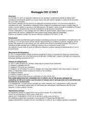
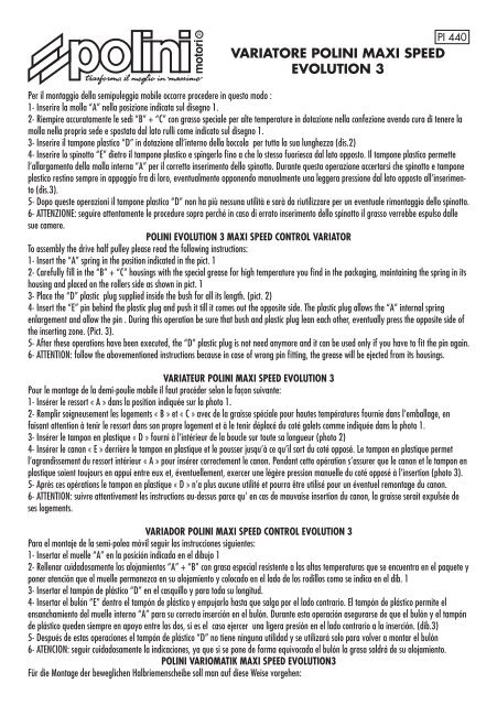
Per il montaggio della semipuleggia mobile occorre procedere in questo modo :<br />
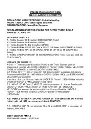
1- Inserire la molla “A” nella posizione indicata sul disegno 1.<br />
2- Riempire accuratamente le sedi “B” + “C” con grasso speciale per alte temperature in dotazione nella confezione avendo cura di tenere la<br />
molla nella propria sede e spostata dal lato rulli come indicato sul disegno 1.<br />
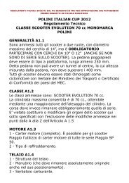
3- Inserire il tampone plastico “D” in dotazione all’interno della boccola per tutta la sua lunghezza (dis.2)<br />
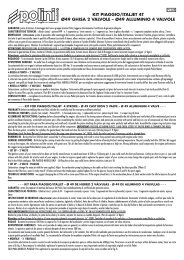
4- Inserire lo spinotto “E” dietro il tampone plastico e spingerlo fino a che lo stesso fuoriesca dal lato opposto. Il tampone plastico permette<br />
l’allargamento della molla interna “A” per il corretto inserimento dello spinotto. Durante questa operazione accertarsi che spinotto e tampone<br />
plastico restino sempre in appoggio fra di loro, eventualmente opponendo manualmente una leggera pressione dal lato opposto all’inserimento<br />
(dis.3).<br />
5- Dopo queste operazioni il tampone plastico “D” non ha più nessuna utilità e sarà da riutilizzare per un eventuale rimontaggio dello spinotto.<br />
6- ATTENZIONE: seguire attentamente le procedure sopra perché in caso di errato inserimento dello spinotto il grasso verrebbe espulso dalle<br />
sue camere.<br />
<strong>POLINI</strong> <strong>EVOLUTION</strong> 3 <strong>MAXI</strong> <strong>SPEED</strong> CONTROL VARIATOR<br />
To assembly the drive half pulley please read the following instructions:<br />
1- Insert the “A” spring in the position indicated in the pict. 1<br />
2- Carefully fill in the “B” + “C” housings with the special grease for high temperature you find in the packaging, maintaining the spring in its<br />
housing and placed on the rollers side as shown in pict. 1<br />
3- Place the “D” plastic plug supplied inside the bush for all its length. (pict. 2)<br />
4- Insert the “E” pin behind the plastic plug and push it till it comes out the opposite side. The plastic plug allows the “A” internal spring<br />
enlargement and allow the pin . During this operation be sure that bush and plastic plug lean each other, eventually press the opposite side of<br />
the inserting zone. (Pict. 3).<br />
5- After these operations have been executed, the “D” plastic plug is not need anymore and it can be used only if you have to fit the pin again.<br />
6- ATTENTION: follow the abovementioned instructions because in case of wrong pin fitting, the grease will be ejected from its housings.<br />
VARIATEUR <strong>POLINI</strong> <strong>MAXI</strong> <strong>SPEED</strong> <strong>EVOLUTION</strong> 3<br />
Pour le montage de la demi-poulie mobile il faut procéder selon la façon suivante:<br />
1- Insérer le ressort « A » dans la position indiquée sur la photo 1.<br />
2- Remplir soigneusement les logements « B » et « C » avec de la graisse spéciale pour hautes températures fournie dans l’emballage, en<br />
faisant attention à tenir le ressort dans son propre logement et à le tenir déplacé du coté galets comme indiquée dans la photo 1.<br />
3- Insérer le tampon en plastique « D » fourni à l’intérieur de la boucle sur toute sa longueur (photo 2)<br />
4- Insérer le canon « E » derrière le tampon en plastique et le pousser jusqu’à ce qu’il sort du coté opposé. Le tampon en plastique permet<br />
l’agrandissement du ressort intérieur « A » pour insérer correctement le canon. Pendant cette opération s’assurer que le canon et le tampon en<br />
plastique soient toujours en appui entre eux et, éventuellement, exercer une légère pression manuelle du coté opposé à l’insertion (photo 3).<br />
5- Après ces opérations le tampon en plastique « D » n’a plus aucune utilité et pourra être utilisé pour un éventuel remontage du canon.<br />
6- ATTENTION: suivre attentivement les instructions au-dessus parce qu’ en cas de mauvaise insertion du canon, la graisse serait expulsée de<br />
ses logements.<br />
VARIADOR <strong>POLINI</strong> <strong>MAXI</strong> <strong>SPEED</strong> CONTROL <strong>EVOLUTION</strong> 3<br />
Para el montaje de la semi-polea móvil seguir las instrucciones siguientes:<br />
1- Insertar el muelle “A” en la posición indicada en el dibujo 1<br />
2- Rellenar cuidadosamente los alojamientos “A” + “B” con grasa especial resistente a las altas temperaturas que se encuentra en el paquete y<br />
poner atención que el muelle permanezca en su alojamiento y colocado en el lado de los rodillos como se indica en el dib. 1<br />
3- Insertar el tampón de plástico “D” en el casquillo y para toda su longitud.<br />
4- Insertar el bulón “E” dentro el tampón de plástico y empujarlo hasta que salga por el lado contrario. El tampón de plástico permite el<br />
ensanchamiento del muelle interno “A” para su correcta inserción en el bulón. Durante esta operación asegurarse de que el bulón y el tampón<br />
de plástico queden siempre en apoyo entre los dos, si es el caso ejercer una ligera presión en el lado contrario a la inserción. (dib.3)<br />
5- Después de estas operaciones el tampón de plástico “D” no tiene ninguna utilidad y se utilizará solo para volver a montar el bulón<br />
6- ATENCION: seguir cuidadosamente la indicaciones, ya que si se pone de forma equivocada el bulón la grasa saldrá de su alojamiento.<br />
<strong>POLINI</strong> VARIOMATIK <strong>MAXI</strong> <strong>SPEED</strong> <strong>EVOLUTION</strong>3<br />
Für die Montage der beweglichen Halbriemenscheibe soll man auf diese Weise vorgehen:
1- Die Feder „A“ wie im Bild 1 einsetzen.<br />
2- Die Sitze „B“ und „C“ sorgfältig mit der belieferten Spezialschmiere für Hochtemperaturen füllen. Die Feder in ihrem Sitz halten und sie wie<br />
im Bild 1 von der Rollenseite verrücken.<br />
3- Der belieferte Puffer aus Plastik „D“ in der Büchse ganz einsetzten (Bild 2).<br />
4- Der Bolzen „E“ hinter des Plastikpuffers einsetzten und er bis zu seinem Austritt auf die gegenüber Seite schieben. Der Plastikpuffer erlaubt<br />
die Überschwemmung der Innerfeder „A“ für die korrekte Einsetzung des Bolzens. Während dieser Phase sich überzeugen, dass Bolzen und<br />
Plastikpuffer immer in Stütze sind. Falls notwending, eine leichte Pression auf die gegenüber Seite handlich entgegen setzen (Bild 3).<br />
5- Nach diesen Operationen, der Plastikpuffer „D“ wird unnütz; man wird ihn für eine eventuelle Re-Montage des Bolzens verwenden.<br />
6- ACHTUNG: das Verfahren aufmerksam folgen, da, solltet das Bolzen falsch eingesetzt werden, wird die Schmiere von ihren Sitze ausgeschlossen.<br />
1<br />
DETTAGLIO CAMERE PER GRASSO - DETAILS OF THE GREASE HOUSINGS<br />
DETAIL LOGEMENTS POUR GRAISSE - ALOJAMIENTOS GRASA<br />
SITZES DETAIL FÜR SCHMIERE<br />
3<br />
B<br />
C<br />
B<br />
2<br />
B<br />
A<br />
D<br />
E<br />
C