You also want an ePaper? Increase the reach of your titles
YUMPU automatically turns print PDFs into web optimized ePapers that Google loves.
<strong>Sistemi</strong> <strong>per</strong><br />
<strong>acqua</strong> <strong>refrigerata</strong><br />
Chilled water systems
sistemi <strong>per</strong> <strong>acqua</strong> <strong>refrigerata</strong><br />
chilled water systems
indice/contents<br />
SISTEMI PER ACQUA REFRIGERATA<br />
CHILLED WATER SYSTEMS<br />
Serbatoi singolo anello / Single circuit tanks<br />
V / VK / VKT / VKG / VKX<br />
Serbatoi doppio anello / Double circuit tanks<br />
VKS / VKR / VKD<br />
<strong>Sistemi</strong> Idronici / Hydronic systems<br />
HPT<br />
HP<br />
VKB<br />
Termoaccumuli puffer caldo-freddo / Puffer hot-chilled water storage units<br />
PUFFER HC<br />
Termoaccumuli puffer compatti caldo-freddo / Compact puffer hot-chilled water storage units<br />
A-AM-AMI<br />
Ricambi-Supplementi-Accessori / Spare parts-Ancillary parts-Accessories<br />
06<br />
08<br />
10<br />
12<br />
14<br />
17<br />
18<br />
20<br />
22
Serbatoi <strong>acqua</strong> <strong>refrigerata</strong><br />
Chilled water tanks<br />
04<br />
Abbinamenti suggeriti<br />
Suggested matching<br />
V<br />
VK<br />
VKT<br />
VKG<br />
VKX<br />
VKS<br />
VKR<br />
VKD<br />
SINGOLO ANELLO<br />
SINGLE CIRCUIT<br />
DOPPIO ANELLO<br />
DOUBLE CIRCUIT<br />
I serbatoi <strong>per</strong> <strong>acqua</strong> <strong>refrigerata</strong> Fiorini sono stati progettati <strong>per</strong><br />
risolvere il problema dell’inerzia termica negli impianti di<br />
condizionamento e refrigerazione idronici.<br />
L’aumento della capacità dell’impianto, ottenibile con<br />
l’adozione di un serbatoio, consente di ottenere molteplici<br />
benefici, tra cui:<br />
• maggiore durata delle macchine frigorifere dovuta ad un<br />
minor numero di avviamenti delle macchine stesse;<br />
• maggiore economia d’esercizio dovuta alla possibilità di<br />
installare macchine frigorifere di potenza ridotta.<br />
Fiorini chilled water tanks have been specially designed to<br />
tackle the problem of thermal inertia in conditioning and<br />
cooling systems.<br />
The tank enhances the system <strong>per</strong>formance, thus proving a<br />
number of advantages, including:<br />
• longer life of the refrigerating systems thanks to a reduced<br />
number of starts-up;<br />
• higher saving on running costs as lower-power units can be<br />
installed.<br />
Impianti a singolo anello e doppio anello<br />
Fiorini propone una gamma completa di serbatoi <strong>per</strong> <strong>acqua</strong> <strong>refrigerata</strong>. Sono disponibili<br />
versioni specifiche <strong>per</strong> impianti a singolo e doppio anello.<br />
Singolo anello: il serbatoio, posto in serie all’impianto ed al refrigeratore, svolge la funzione<br />
di volano termico.<br />
Plus: Semplice installazione; economicità.<br />
Doppio anello: il serbatoio svolge la duplice funzione di volano termico e separatore idraulico.<br />
La proposta di Fiorini prevede serbatoi dotati di sistemi <strong>per</strong> il convogliamento preferenziale<br />
dell’<strong>acqua</strong> all’interno dello stesso.<br />
Plus: Possibilità di avere portate diverse nel circuito primario e secondario; massima<br />
flessibilità.<br />
Single or double circuit plants<br />
Fiorini supplies a complete range of chilled water tanks. A number of versions are available<br />
for single or double circuit plants.<br />
Single circuit: the tank installed in series with the plant and the chiller works as a thermal<br />
flywheel.<br />
Advantages: Easy assembly; cost-effectiveness<br />
Double circuit: the tank has the twofold function of thermal flywheel and hydraulic separator.<br />
Fiorini tanks are complete with systems for the preferential deviation of water into it.<br />
Advantages: Possibility to have different flow rates in the primary and secondary circuits.<br />
Maximum flexibility.
05<br />
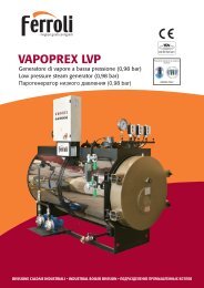
Impianto a singolo anello - Schema con accumulo sul ritorno/Single circuit plant - Layout with storage tank on return<br />
Alimentazione<br />
Impianto/<br />
Plant supply<br />
Scarico / Drain<br />
Impianto a doppio anello - Schema di impianto a doppio circuito/Double circuit plant - Layout of double circuit plant<br />
Scarico / Drain<br />
Alimentazione<br />
Impianto/<br />
Plant supply
06<br />
Serbatoi <strong>acqua</strong> <strong>refrigerata</strong><br />
Chilled water tanks<br />
V-VK-VKT-VKG-VKX<br />
TEMPERATURA<br />
tem<strong>per</strong>ature<br />
PRESSIONE<br />
pressure<br />
V -10 / + 60 °C 6 bar<br />
VK -10 / + 60 °C 6 bar<br />
VKT -10 / + 60 °C 6 bar<br />
VKG -10 / + 60 °C 6 bar<br />
VKX -10 / + 60 °C 6 bar<br />
ESECUZIONI SPECIALI<br />
Disponibili esecuzioni speciali<br />
su richiesta. Dimensioni<br />
<strong>per</strong>sonalizzate e attacchi.<br />
SPECIAL EXECUTION<br />
Special execution available on<br />
request, including customized<br />
dimensions, couplings.<br />
Serbatoi Singolo Anello<br />
Serbatoi <strong>per</strong> <strong>acqua</strong> <strong>refrigerata</strong> progettati <strong>per</strong><br />
essere installati in impianti di condizionamento e<br />
refrigerazione <strong>per</strong> aumentarne l’inerzia termica.<br />
Impiego<br />
Utilizzati in tutti gli impianti di condizionamento<br />
idronici <strong>per</strong> aumentare l’inerzia termica del<br />
sistema.<br />
Specialmente indicati <strong>per</strong> gli impianti a singolo<br />
anello.<br />
Single circuit tanks<br />
Storage tanks for chilled water specially designed<br />
for conditioning and cooling systems to increase<br />
thermal inertia.<br />
Use<br />
Suitable for all hydronic conditioning systems to<br />
increase thermal inertia.<br />
Recommended for single circuit plants.<br />
SERIE V: Serbatoio in acciaio al carbonio<br />
zincato a caldo non coibentato.<br />
SERIE VK: Serbatoio in acciaio al carbonio<br />
zincato a caldo con coibentazione in<br />
elastomero espanso a cellula chiusa con<br />
funzione anti-condensa spessore 20 mm.<br />
SERIE VKT: Serbatoio in acciaio al<br />
carbonio zincato a caldo e trattato<br />
internamente con smaltatura alimentare<br />
Zetaflon, coibentazione in elastomero<br />
espanso a cellula chiusa con funzione<br />
anti-condensa spessore 20 mm.<br />
SERIE VKG: Serbatoio in acciaio al<br />
carbonio verniciato esternamente con<br />
coibentazione in elastomero espanso a<br />
cellula chiusa con funzione anti-condensa<br />
spessore 20 mm.<br />
SERIE VKX: Serbatoio in acciaio inox AISI<br />
304 con coibentazione in elastomero<br />
espanso a cellula chiusa con funzione<br />
anti-condensa spessore 20 mm.<br />
V SERIES: Non-insulated hot-dip<br />
galvanised carbon steel tank.<br />
VK SERIES: Hot-dip galvanised carbon<br />
steel tank insulated with 20 mm closedcell<br />
elastomeric foam preventing the<br />
formation of condensate.<br />
VKT SERIES: Hot-dip galvanised carbon<br />
steel tank internally coated with Zetaflon<br />
enamel suitable for food contact,<br />
insulated with 20 mm closed-cell<br />
elastomeric foam preventing the<br />
formation of condensate.<br />
VKG SERIES: carbon steel tank with<br />
painted outer face, insulated with 20 mm<br />
closed-cell elastomeric foam preventing<br />
the formation of condensate.<br />
VKX SERIES: AISI 304 stainless steel tank,<br />
insulated with 20 mm closed-cell<br />
elastomeric foam preventing the<br />
formation of condensate.<br />
V<br />
vk<br />
vkt<br />
vkg<br />
vkx<br />
H<br />
K<br />
COIBENTAZIONE<br />
INSULATION<br />
1 1<br />
1<br />
L<br />
ACCIAIO AL<br />
CARBONIO<br />
CARBON<br />
STEEL<br />
1<br />
ZINCATURA A<br />
CALDO<br />
HOT-DIP<br />
GALVANIZING<br />
D<br />
H<br />
ACCIAIO INOX<br />
AISI 304<br />
STAINLESS STEEL<br />
AISI 304<br />
1<br />
1<br />
K<br />
SMALTATURA<br />
ZETAFLON<br />
ZETAFLON ENAMEL<br />
COATING<br />
D<br />
1<br />
1<br />
A<br />
VERNICIATURA<br />
ANTIRUGGINE<br />
RUSTPROOF<br />
PAINTING<br />
B
07<br />
Elenco codici esecuzione verticale<br />
Vertical version code list<br />
Volume(l) V VK VKT VKG VKX<br />
100 816020040 816020064 816030030 816010130 816040020<br />
200 816020041 816020065 816030031 816010131 816040021<br />
300 816020042 816020066 816030032 816010132 816040022<br />
500 816020043 816020067 816030033 816010133 816040023<br />
800 816020044 816020068 816030034 816010134 816040024<br />
1000 816020045 816020069 816030035 816010135 816040025<br />
1500 816020046 816020070 816030036 816010136 816040026<br />
2000 816020047 816020071 816030037 816010137 816040027<br />
2500 816020048 816020072 816030038 816010138 816040028<br />
3000 816020049 816020073 816030039 816010139 816040029<br />
4000 816020050 816020074 816030040 816010140 816040030<br />
5000 816020051 816020075 816030041 816010141 816040031<br />
Elenco codici esecuzione orizzontale<br />
Horizontal version code list<br />
Volume(l) V VK VKT VKG VKX<br />
100 816020052 816020076 816030042 816010142 816040032<br />
200 816020053 816020077 816030043 816010143 816040033<br />
300 816020054 816020078 816030044 816010144 816040034<br />
500 816020055 816020079 816030045 816010145 816040035<br />
800 816020056 816020080 816030046 816010146 816040036<br />
1000 816020057 816020081 816030047 816010147 816040037<br />
1500 816020058 816020082 816030048 816010148 816040038<br />
2000 816020059 816020083 816030049 816010149 816040039<br />
2500 816020060 816020084 816030050 816010150 816040040<br />
3000 816020061 816020085 816030051 816010151 816040041<br />
4000 816020062 816020086 816030052 816010152 816040042<br />
5000 816020063 816020087 816030053 816010153 816040043<br />
V / VK / VKT / VKG - Verticale/Vertical<br />
Capacità<br />
Capacity<br />
D H K A B 1<br />
(litri/liters)<br />
(mm)<br />
100 440 950 125 290 760 1”1/2<br />
200 490 1340 125 295 1145 1”1/2<br />
300 590 1425 130 365 1165 2”<br />
500 690 1710 135 385 1435 3”<br />
800 830 1741 125 395 1445 3”<br />
1000 890 2026 120 410 1710 3”<br />
1500 1040 2163 165 500 1800 3”<br />
2000 1140 2483 155 505 2105 3”<br />
2500 1240 2563 175 555 2155 4”<br />
3000 1290 2778 180 565 2365 4”<br />
4000 1440 2848 160 590 2390 4”<br />
5000 1640 2888 140 600 2400 4”<br />
VKX - Verticale/Vertical<br />
Capacità<br />
Capacity<br />
D H K A B 1<br />
(litri/liters)<br />
(mm)<br />
100 440 980 135 315 775 1”1/2<br />
200 490 1370 135 320 1160 1”1/2<br />
300 590 1425 130 365 1165 2”<br />
500 690 1710 135 385 1435 3”<br />
800 790 1995 130 400 1700 3”<br />
1000 890 2025 120 410 1710 3”<br />
1500 990 2485 225 540 2140 3”<br />
2000 1140 2535 210 560 2160 3”<br />
2500 1240 2600 200 580 2180 4”<br />
3000 1290 2800 205 590 2390 4”<br />
4000 1440 2900 190 625 2425 4”<br />
5000 1640 2930 170 630 2430 4”<br />
V / VK / VKT / VKG - Orizzontale/Horizontal<br />
Capacità<br />
Capacity<br />
D H L K 1<br />
(litri/liters)<br />
(mm)<br />
100 440 546 850 120 1”1/2<br />
200 490 596 1240 120 1”1/2<br />
300 590 715 1320 140 2”<br />
500 690 875 1600 190 3”<br />
800 830 1015 1642 190 3”<br />
1000 890 1075 1932 190 3”<br />
1500 1040 1275 2010 190 3”<br />
2000 1140 1335 2356 200 3”<br />
2500 1240 1460 2416 225 4”<br />
3000 1290 1510 2626 225 4”<br />
4000 1440 1660 2716 225 4”<br />
5000 1640 1680 2776 225 4”<br />
VKX - Orizzontale/Horizontal<br />
Capacità<br />
Capacity<br />
D H L K 1<br />
(litri/liters)<br />
(mm)<br />
100 440 545 870 120 1”1/2<br />
200 490 590 1260 115 1”1/2<br />
300 590 715 1320 140 2”<br />
500 690 825 1600 145 3”<br />
800 790 920 1890 140 3”<br />
1000 890 1015 1930 135 3”<br />
1500 990 1220 2320 240 3”<br />
2000 1140 1375 2350 245 3”<br />
2500 1240 1470 2410 230 4”<br />
3000 1290 1525 2620 235 4”<br />
4000 1440 1660 2720 220 4”<br />
5000 1640 1835 2770 210 4”
08<br />
Serbatoi <strong>acqua</strong> <strong>refrigerata</strong><br />
Chilled water tanks<br />
VKS-VKR-VKD<br />
TEMPERATURA<br />
tem<strong>per</strong>ature<br />
PRESSIONE<br />
pressure<br />
VKS -10 / + 60 °C 6 bar<br />
VKR -10 / + 60 °C 6 bar<br />
VKD -10 / + 60 °C 6 bar<br />
ESECUZIONI SPECIALI<br />
Disponibili esecuzioni speciali<br />
su richiesta. Dimensioni<br />
<strong>per</strong>sonalizzate e attacchi.<br />
SPECIAL EXECUTION<br />
Special execution available on<br />
request, including customized<br />
dimensions, couplings.<br />
Serbatoi Doppio Anello<br />
Serbatoi <strong>per</strong> <strong>acqua</strong> <strong>refrigerata</strong> completi di sistemi <strong>per</strong> il<br />
convogliamento dei flussi, progettato <strong>per</strong> essere installati in<br />
impianti di condizionamento e refrigerazione <strong>per</strong><br />
aumentarne l’inerzia termica.<br />
La presenza di un sistema interno <strong>per</strong> il convogliamento dei<br />
flussi <strong>per</strong>mette di:<br />
• ridurre i tempi di messa a regime dell’impianto grazie al<br />
convogliamento diretto della mandata del circuito primario<br />
verso la mandata dell’impianto;<br />
• creare successivamente un accumulo di <strong>acqua</strong> a bassa<br />
tem<strong>per</strong>atura sfruttando la differenza di portata tra il<br />
circuito primario (refrigeratore) e secondario (impianto).<br />
Impiego<br />
Utilizzati in tutti gli impianti di condizionamento idronici<br />
<strong>per</strong> aumentare l’inerzia termica del sistema.<br />
Specialmente indicati <strong>per</strong> gli impianti a doppio anello con<br />
funzione di disgiuntore idraulico.<br />
Materiali<br />
Serbatoio realizzato in lamiera di acciaio al carbonio<br />
verniciato esternamente, con coibentazione 20 mm in<br />
elastomero espanso a cellula chiusa anticondensa e<br />
rivestimento esterno in PVC colorato.<br />
VKS<br />
Serbatoio dotato di setti divisori che <strong>per</strong>mettono di<br />
evitare flussi preferenziali all’interno del serbatoio<br />
creando le condizioni <strong>per</strong> una distribuzione ottimale<br />
della tem<strong>per</strong>atura. Sistema indicato <strong>per</strong> portate medie ed<br />
elevate. Particolarmente indicato anche nelle esecuzioni<br />
speciali in cui il serbatoio è predisposto <strong>per</strong> essere collegato<br />
a più di due circuiti.<br />
Tanks fitted with partitions to prevent any preferential<br />
flows inside the tank, thus ensuring the conditions for<br />
<strong>per</strong>fect tem<strong>per</strong>ature distribution. Suitable for average<br />
to high flow rates. Specially recommended for special<br />
executions where the tank can be connected to more than<br />
two circuits.<br />
VKR<br />
Serbatoio dotato di tubi convogliatori che creano un<br />
circuito preferenziale all’interno del serbatoio. Sistema<br />
indicato <strong>per</strong> portate medie ed elevate.<br />
Tank fitted with deviating pipes that create a preferential<br />
circuit inside the tank. Suitable for average to high flow<br />
rates.<br />
VKD<br />
Serbatoio dotato di tubi diffusori che collegano<br />
direttamente i due circuiti collegati al serbatoio. Mediante<br />
i fori circonferenziali del diffusore viene ceduta o sottratta<br />
energia all’accumulo. Con questo sistema il fenomeno<br />
della miscelazione all’interno del serbatoio viene ridotto al<br />
minimo. Sistema indicato <strong>per</strong> portate elevate.<br />
Tank fitted with diffusing pipes which directly connect the<br />
two circuits connected to the tank. The circumferential<br />
holes of the diffuser allow to release or absorb power from<br />
the storage. As a result, mixing inside the tank is minimized.<br />
Suitable for high flow rates.
09<br />
Double circuit tanks<br />
Chilled water tanks complete with systems for<br />
flow deviation, specially designed for<br />
installation in conditioning and cooling systems<br />
1<br />
to increase thermal inertia.<br />
The presence of an internal flow deviation<br />
system allow to:<br />
1<br />
• cut down the system start-up time as the<br />
primary circuit delivery is directly deviated<br />
towards the plant delivery;<br />
• subsequently create a low tem<strong>per</strong>ature water<br />
storage by exploiting the flow rate difference H<br />
between primary circuit (chiller) and secondary<br />
B<br />
one (plant).<br />
Use<br />
Suitable for all hydronic conditioning systems to<br />
increase thermal inertia.<br />
Recommended for plants with double circuit to<br />
work as hydraulic separator.<br />
Materials<br />
Carbon steel sheet tanks with painted outer<br />
face, insulated with 20 mm closedcell<br />
1<br />
K<br />
1<br />
A<br />
elastomeric foam preventing the formation of condensate, external finish with coloured PVC.<br />
D<br />
Tabella Dimensioni<br />
Size Table<br />
Capacità<br />
Capacity<br />
(litri/liters)<br />
D H K A B 1<br />
(mm)<br />
100 440 950 125 290 760 1”1/2<br />
200 490 1340 125 295 1145 1”1/2<br />
300 590 1425 130 365 1165 2”<br />
500 690 1710 135 385 1435 3”<br />
800 830 1741 125 395 1445 3”<br />
1000 890 2026 120 410 1710 3”<br />
1500 1040 2163 165 500 1800 3”<br />
2000 1140 2483 155 505 2105 3”<br />
2500 1240 2563 175 555 2155 4”<br />
3000 1290 2778 180 565 2365 4”<br />
4000 1440 2848 160 590 2390 4”<br />
5000 1640 2888 140 600 2400 4”<br />
Elenco Codici<br />
Part no. list<br />
Capacità<br />
Capacity<br />
VKS VKR VKD<br />
100 816010166 816010154 816010417<br />
200 816010167 816010155 816010418<br />
300 816010168 816010156 816010419<br />
500 816010169 816010157 816010420<br />
800 816010170 816010158 816010421<br />
1000 816010171 816010159 816010422<br />
1500 816010172 816010160 816010423<br />
2000 816010173 816010161 816010424<br />
2500 816010174 816010162 816010425<br />
3000 816010175 816010163 816010426<br />
4000 816010176 816010164 816010427<br />
5000 816010177 816010165 816010428
<strong>Sistemi</strong> idronici<br />
Hydronic systems<br />
010<br />
Per sfruttare al meglio i benefici di un volano termico negli impianti di condizionamento e<br />
refrigerazione idronici e <strong>per</strong> ridurre notevolmente i tempi di installazione, Fiorini propone le<br />
unità VKB, HPT ed HP. Si tratta di centrali idrauliche complete di tutti i componenti<br />
indispensabili al corretto funzionamento del circuito idraulico <strong>per</strong> la distribuzione dell’<strong>acqua</strong><br />
<strong>refrigerata</strong> e possono essere abbinate a tutti i refrigeratori d’<strong>acqua</strong>.<br />
Le unità sono racchiuse da una struttura portante che ha il basamento in acciaio verniciato,<br />
telaio e pannellature in lamiera di acciaio zincato e verniciato; il tutto rende le unità<br />
installabili all’esterno.<br />
L’ampia scelta di combinazioni pompa-accumulo consente di soddisfare ogni esigenza<br />
impiantistica.<br />
To make the most out of the thermal flywheel in hydronic conditioning and cooling systems,<br />
as well as to significantly cut down on installation time, Fiorini has designed the VKB, HPT<br />
and HP units. They are storage units complete with all necessary components for the pro<strong>per</strong><br />
o<strong>per</strong>ation of the hydraulic circuit for the distribution of chilled water. They can be combined<br />
with any water chillers.<br />
The units are contained within a support casing with a painted steel base, frame and<br />
panelling in painted galvanized steel sheet. Suitable for outdoor installation.<br />
The possibility of combining several pumps/storage units makes it possible to satisfy any plant<br />
demands.<br />
HPT<br />
Unità con serbatoio, pompe ed accessori<br />
Unit with storage tank, pumps and accessories
011<br />
VKB<br />
Unità con serbatoio ed accessori<br />
Unit with storage tank and accessories<br />
HP<br />
Unità con pompe ed accessori<br />
Unit with pumps and accessories
012<br />
<strong>Sistemi</strong> idronici<br />
Hydronic systems<br />
HPT<br />
TEMPERATURA<br />
tem<strong>per</strong>ature<br />
PRESSIONE<br />
pressure<br />
HPT -10 / + 60 °C 3 bar<br />
ESECUZIONI SPECIALI<br />
Disponibili esecuzioni speciali<br />
su richiesta, ad esempio:<br />
esecuzioni doppio circuito<br />
a 4 attacchi, attacchi<br />
vic-taulic, attacchi flangiati,<br />
abbinamenti pompa accumulo<br />
<strong>per</strong>sonalizzati, inverter, ecc.<br />
SPECIAL EXECUTION<br />
Special execution available on<br />
request, including: double<br />
circuit execution with<br />
4 couplings, Victaulic<br />
couplings, flanged couplings,<br />
customized pump/storage unit<br />
combination, etc.<br />
Le unità HPT sono centrali idrauliche con accumulo<br />
inerziale progettate <strong>per</strong> ridurre i tempi di<br />
allestimento degli impianti di condizionamento e<br />
refrigerazione idronici e possono essere abbinate a<br />
tutti i refrigeratori d’<strong>acqua</strong>. L’ampia scelta di<br />
combinazioni pompa-accumulo consente di<br />
soddisfare ogni esigenza impiantistica.<br />
Componenti principali:<br />
- Serbatoio in acciaio al carbonio coibentato.<br />
- Pompa centrifuga singola o doppia con valvola di<br />
intercettazione<br />
- Quadro elettrico di potenza e controllo IP56.<br />
- Vaso di espansione.<br />
- Valvola di sicurezza.<br />
- Disaeratore.<br />
- Manometro.<br />
- Valvole di carico/scarico.<br />
- Basamento e pannellatura idonea all’istallazione in esterni.<br />
The HPT units are hydraulic stations with inertial storage intended for installation in hydronic<br />
conditioning and cooling systems, developed to cut down on installation times and to be combined<br />
with any water chillers. The possibility of combining several pumps/storage units makes it possible<br />
to satisfy any plant demands.<br />
Main components:<br />
- Insulated carbon steel tank<br />
- Single or double centrifugal pump with shut-off valve<br />
- Electric power board and IP56 protection rating<br />
- Expansion tank<br />
- Safety valve<br />
- Pressure relief valve<br />
- Dearator<br />
- Pressure gauge<br />
- Fill/drain valves<br />
- Base frame and panelling suitable for outdoor installation<br />
HPT<br />
Unità con serbatoio, pompe ed accessori<br />
Unit with storage tank, pumps and accessories
013<br />
A<br />
B<br />
A<br />
B<br />
H<br />
H<br />
Disposizione verticale<br />
Vertical Configuration<br />
Disposizione orizzontale<br />
Horizontal Configuration<br />
Capacità<br />
Capacity<br />
(liter)<br />
A B H<br />
Diametro Attacchi<br />
Coupling Diameter<br />
Capacità<br />
Capacity<br />
(liter)<br />
A B H<br />
Diametro Attacchi<br />
Coupling Diameter<br />
100 1120 800 1350 1”1/2<br />
200 1120 800 1350 1”1/2<br />
300 1100 760 1726 2”1/2<br />
300/500 1504 1120 1265 2”1/2<br />
750/1000 2044 1200 1510 3”<br />
1500/2500 2260 1900 1782 4”<br />
Elenco Codici/Part no. list<br />
Modello pompa<br />
Capacità/ Capacity<br />
Pump model<br />
100l<br />
Tipo/Type SINGOLA/SINGLE DOPPIA/DOUBLE<br />
PM1 838011058X 838011059X<br />
PM2 838011060X 838011061X<br />
PM3 838011072X 838011074X<br />
Modello pompa<br />
Pump model<br />
Capacità/ Capacity<br />
200l<br />
Tipo/Type SINGOLA/SINGLE DOPPIA/DOUBLE<br />
PM1 838011062X 838011063X<br />
PM2 838011064X 838011065X<br />
PM3 838011073X 838011075X<br />
Modello pompa<br />
Pump model<br />
Capacità/ Capacity<br />
300l<br />
Tipo/Type SINGOLA/SINGLE DOPPIA/DOUBLE<br />
A 838010891X 838010896X<br />
B 838010892X 838010897X<br />
C 838010893X 838010898X<br />
D 838010894X 838010899X<br />
E 838010895X 838010900X<br />
Le pompe utilizzate nei gruppi sono 400v/50hz/3ph ad eccezione della PM1, PM2 e PM3<br />
che sono 230V/50hz/1 ph. Consultare pagina 16 <strong>per</strong> conoscere le prestazioni delle pompe.<br />
The pumps used in the units are 400v/50hz/3ph except for PM1, PM2 and PM3<br />
that are 230V/50hz/1 ph. See page 16 for information on pump <strong>per</strong>formances.<br />
Elenco Codici/Part no. list<br />
Modello pompa<br />
Pump model<br />
Capacità/ Capacity<br />
300l<br />
Capacità/ Capacity<br />
500l<br />
Tipo/Type SINGOLA/SINGLE DOPPIA/DOUBLE SINGOLA/SINGLE DOPPIA/DOUBLE<br />
A 838010349 838010354 838010359 838010364<br />
B 838010350 838010355 838010360 838010365<br />
C 838010351 838010356 838010361 838010366<br />
D 838010352 838010357 838010362 838010367<br />
E 838010353 838010358 838010363 838010368<br />
Modello pompa<br />
Pump model<br />
Capacità/ Capacity<br />
750l<br />
Capacità/ Capacity<br />
1000l<br />
Tipo/Type SINGOLA/SINGLE DOPPIA/DOUBLE SINGOLA/SINGLE DOPPIA/DOUBLE<br />
F 838010374 838010379 838010384 838010389<br />
G 838010375 838010380 838010385 838010390<br />
H 838010376 838010381 838010386 838010391<br />
I 838010377 838010382 838010387 838010392<br />
L 838010378 838010383 838010388 838010393<br />
Modello pompa<br />
Pump model<br />
Capacità/ Capacity<br />
1500l<br />
Capacità/ Capacity<br />
2500l<br />
Tipo/Type SINGOLA/SINGLE DOPPIA/DOUBLE SINGOLA/SINGLE DOPPIA/DOUBLE<br />
F 838010705 838010458 838010689 838010682<br />
G 838010704 838010630 838010688 838010681<br />
H 838010703 838010696 838010687 838010680<br />
I 838010702 838010695 838010686 838010679<br />
L 838010701 838010694 838010685 838010678<br />
M 838010700 838010693 838010684 838010677<br />
O 838010699 838010692 838010707 838010459<br />
P 838010698 838010691 838010683 838010676<br />
Q 838010697 838010690 838010706 838010633
014<br />
<strong>Sistemi</strong> idronici<br />
Hydronic systems<br />
HP<br />
TEMPERATURA<br />
tem<strong>per</strong>ature<br />
PRESSIONE<br />
pressure<br />
HP -10 / + 60 °C 3 bar<br />
ESECUZIONI SPECIALI<br />
Disponibili esecuzioni speciali<br />
su richiesta, ad esempio:<br />
attacchi Vic-taulic, attacchi<br />
flangiati, inverter, ecc.<br />
SPECIAL EXECUTION<br />
Special execution available on<br />
request, including: Victaulic<br />
couplings, flanged couplings,<br />
inverter, etc.<br />
Le unità HP sono centrali idrauliche progettate <strong>per</strong><br />
ridurre i tempi di allestimento degli<br />
impianti di condizionamento e refrigerazione<br />
idronici e possono essere abbinate a tutti<br />
i refrigeratori d’<strong>acqua</strong>. L’ampia scelta di pompe<br />
consente di soddisfare ogni esigenza<br />
impiantistica. Le unità HP possono inoltre essere<br />
abbinate a tutta la gamma di serbatoi e<br />
scambiatori di calore a piastre Fiorini.<br />
Componenti principali:<br />
- Pompa centrifuga singola o doppia con valvola di<br />
intercettazione<br />
- Quadro elettrico di potenza e controllo IP56.<br />
- Vaso di espansione.<br />
- Valvola di sicurezza.<br />
- Disaeratore.<br />
- Manometro.<br />
- Valvole di carico/scarico.<br />
- Basamento e pannellatura idonea all’istallazione<br />
in esterni.<br />
The HP units are hydraulic stations with inertial storage intended for installation in<br />
hydronic conditioning and cooling systems, developed to cut down on installation times<br />
and to be combined with any water chillers. The wide range of pumps makes it possible to<br />
satisfy any plant demands. The HP units can be combined with the whole range of Fiorini<br />
tanks and plate heat exchangers.<br />
Main components:<br />
- Single or double centrifugal pump with shut-off valve<br />
- Electric power board and IP56 protection rating<br />
- Expansion tank<br />
- Safety valve<br />
- Deaerator.<br />
- Pressure gauge<br />
- Fill/drain valves<br />
- Base frame and panelling suitable for outdoor installation<br />
HP<br />
Unità con pompe ed accessori<br />
Unit with pumps and accessories
015<br />
Y<br />
X<br />
Z<br />
T<br />
S<br />
U<br />
Modello Pompa<br />
Pump Model<br />
kIT HP<br />
SIZE 1 SIZE 2 SIZE 3 X Y Z S T U<br />
PM1-N 838060052X 800 650 1350 210 600 475<br />
PM1-R 838060053X 800 650 1350 210 600 475<br />
PM2-N 838060054X 800 650 1350 210 600 475<br />
PM2-R 838060055X 800 650 1350 210 600 475<br />
PM3-N 838060056X 800 650 1350 210 600 475<br />
PM3-R 838060057X 800 650 1350 210 600 475<br />
AN 838060009 800 650 1350 210 600 475<br />
AR 838060014 800 650 1350 210 600 475<br />
BN 838060010 800 650 1350 210 600 475<br />
BR 838060015 800 650 1350 210 600 475<br />
CN 838060011 800 650 1350 210 600 475<br />
CR 838060016 800 650 1350 210 600 475<br />
DN 838060012 800 650 1350 210 600 475<br />
DR 838060017 800 650 1350 210 600 475<br />
EN 838060013 800 650 1350 210 600 475<br />
ER 838060018 800 650 1350 210 600 475<br />
FN 838060019 1120 800 1350 250 790 605<br />
FR 838060028 1120 800 1350 250 790 605<br />
GN 838060020 1120 800 1350 250 790 605<br />
GR 838060029 1120 800 1350 250 790 605<br />
HN 838060021 1120 800 1350 250 790 605<br />
HR 838060030 1120 800 1350 250 790 605<br />
IN 838060022 1120 800 1350 250 790 605<br />
IR 838060031 1120 800 1350 250 790 605<br />
LN 838060023 1120 800 1350 250 790 605<br />
LR 838060032 1200 1000 1350 270 750 490<br />
MN 838060024 1120 800 1350 250 790 605<br />
MR 838060033 1200 1000 1350 270 750 490<br />
ON 838060025 1120 800 1350 270 790 195<br />
OR 838060034 1200 1000 1350 270 750 490<br />
PN 838060026 1120 800 1350 270 790 195<br />
PR 838060035 1200 1000 1350 270 750 490<br />
Consultare pagina 16 <strong>per</strong> conoscere le prestazioni delle pompe<br />
See page 16 for information on pum <strong>per</strong>formances
016<br />
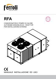
Curva portata-prevalenza gruppo HPT e HP<br />
Flow rate/head curve – HPT and HP units<br />
25,00<br />
30,00<br />
20,00<br />
PM3 - MUH 502<br />
25,00<br />
20,00<br />
B - DWC 300/1,5<br />
H [m]<br />
15,00<br />
PM221 - MUH - 302<br />
H [m]<br />
15,00<br />
A - DWC 300/1,1<br />
10,00<br />
PM1 - MUH 102<br />
10,00<br />
5,00<br />
5,00<br />
∆P<br />
0,00<br />
0 1 2 3 4 5 6 7 8 9<br />
Portata [m [m 3 /h] 3 /h]<br />
0,00<br />
0<br />
5<br />
10<br />
ΔP<br />
Portata [m 3 /h]<br />
15<br />
20<br />
25<br />
30,00<br />
35,00<br />
25,00<br />
E - DWC 500/3,0<br />
30,00<br />
G - FHE 50-160/55<br />
20,00<br />
D - DWC 500/2,2<br />
25,00<br />
H [m]<br />
15,00<br />
C - DWC 500/1,5<br />
H [m]<br />
20,00<br />
15,00<br />
F - FHE 50-125/30<br />
10,00<br />
10,00<br />
5,00<br />
ΔP<br />
0,00<br />
0 5 10 15 20 25 30 35 40 45 50<br />
Portata [m 3 /h]<br />
5,00<br />
P<br />
0,00<br />
0 10 20 30 40 50 60 70 80 90<br />
Portata [m 3 /h]<br />
45,00<br />
35,00<br />
40,00<br />
30,00<br />
G - FHE 50-160/55<br />
35,00<br />
M - FHE 65-160/150<br />
25,00<br />
H [m]<br />
30,00<br />
25,00<br />
20,00<br />
15,00<br />
H - FHE 65-125/55<br />
L - FHE 65-160/110<br />
I - FHE 65-125/75<br />
H [m]<br />
20,00<br />
15,00<br />
10,00<br />
F- FHE 50-125/30<br />
10,00<br />
5,00<br />
P<br />
5,00<br />
P<br />
0,00<br />
0 20 40 60 80 100 120 140 160<br />
0,00<br />
0 10 20 30 40 50 60 70 80 90<br />
Portata [m 3 /h]<br />
Portata [m 3 /h]<br />
Portata [m 3 /h]<br />
45,00<br />
60,00<br />
40,00<br />
35,00<br />
M - FHE 65-160/150<br />
50,00<br />
30,00<br />
L - FHE 65-160/110<br />
40,00<br />
Q - FHE 80-200/220<br />
H [m]<br />
25,00<br />
20,00<br />
15,00<br />
H - FHE 65-125/55<br />
I - FHE 65-125/75<br />
H [m]<br />
30,00<br />
20,00<br />
O - FHE 80-160/150<br />
P - FHE 80-160/185<br />
10,00<br />
5,00<br />
P<br />
0,00<br />
0 20 40 60 80 100 120 140 160<br />
Portata [m 3 /h]<br />
10,00<br />
0,00<br />
0<br />
50<br />
P<br />
100<br />
Portata [m 3 /h]<br />
150<br />
200<br />
250<br />
ΔP: <strong>per</strong>dite di carico gruppo HP / ΔP: HP unit load losses
Accumuli inerziali accessoriati<br />
Inertial storage units with accesories<br />
VKB<br />
017<br />
Serie VKB - Accumulo Inerziale accessoriato<br />
Unità preassemblata composta da: serbatoio inerziale coibentato <strong>per</strong> <strong>acqua</strong> <strong>refrigerata</strong>, vaso<br />
d’espansione, valvola di sicurezza, disaeratore, valvola di carico/scarico e manometro.<br />
Il tutto è contenuto in un robusto contenitore <strong>per</strong> esterni realizzato in lamiera d’acciaio<br />
zincato e verniciato.<br />
VKB series – Inertial storage unit with accessories<br />
Pre-assembled units consisting of the following: insulated inertial tank for chilled water,<br />
expansion tank, pressure relief valve, deaerator, fill/drain valve and pressure gauge.<br />
The assembly is contained within a heavy-duty painted galvanized steel sheet casing<br />
suitable for outdoor use.<br />
A<br />
B<br />
TEMPERATURA PRESSIONE<br />
tem<strong>per</strong>ature pressure<br />
VKB -10 / + 60 °C 3 bar<br />
H<br />
Capacità/Capacity A B H Peso a vuoto/Empty weight Diametro attacchi Codice/Part no.<br />
(litri/litres) (mm) (Kg)<br />
Coupling diameter<br />
200 690 690 1550 90 2” 838050011<br />
300 790 890 1650 100 2” 838050012<br />
500 1200 1200 1950 160 3” 838050013<br />
750 1200 1200 1950 185 3” 838050014<br />
1000 1200 1450 1950 200 4” 838050015<br />
1500 1200 1450 1950 290 4” 838050016
018<br />
Termoaccumuli puffer caldo-freddo<br />
Puffer hot-chilled water storage units<br />
PUFFER HC<br />
TEMPERATURA<br />
tem<strong>per</strong>ature<br />
PRESSIONE<br />
pressure<br />
Puffer HC -10 / + 90 °C 5 bar<br />
ESECUZIONI SPECIALI<br />
Disponibili esecuzioni<br />
speciali su richiesta:<br />
dimensioni <strong>per</strong>sonalizzate,<br />
attacchi flangiati, attacchi<br />
<strong>per</strong>sonalizzati, coibentazione<br />
maggiorata, ecc.<br />
SPECIAL EXECUTION<br />
Special execution available on<br />
request, including: customized<br />
dimensions, flangedcouplings,<br />
customized couplings, thicker<br />
insulation, etc.<br />
I serbatoi PUFFER HC sono solitamente utilizzati in tutti<br />
quegli impianti in cui si ha la doppia esigenza di stoccare<br />
<strong>acqua</strong> tecnologica sia calda che <strong>refrigerata</strong>.<br />
Sono stati studiati appositamente <strong>per</strong> <strong>per</strong>mettere un <strong>per</strong>fetto<br />
accoppiamento a pompe di calore e chiller. Gli attacchi<br />
principali infatti sono di grandi dimensioni <strong>per</strong> poter<br />
consentire il passaggio di portate elevate. Sono inoltre<br />
disponibili numerose connessioni ausiliarie che <strong>per</strong>mettono di<br />
risolvere qualunque esigenza impiantistica.<br />
La coibentazione è realizzata con un doppio strato. Il primo di<br />
10 mm di spessore in elastomero espanso a cellula chiusa in<br />
grado di prevenire la formazione di condensa, il secondo di 40<br />
mm in poliuretano flessibile <strong>per</strong> ridurre al minimo le<br />
dis<strong>per</strong>sioni termiche.<br />
Il tutto è rivestito con mantello in PVC colorato.<br />
The PUFFER HC water tanks are generally installed in plants<br />
where both hot and chilled technological water has to be<br />
stored.<br />
They have been specially designed for coupling to heat pumps and chillers. The main<br />
couplings are indeed large-sized to allow for high flow rates pass through.<br />
A set of auxiliary couplings are also available to meet any plant demands.<br />
Double-layer insulation is provided. The first layer is made of 10 mm closed-cell elastomeric<br />
foam preventing the formation of condensate, whereas the second layer is 40 mm<br />
polyurethane foam to minimize loss of heat.<br />
The whole tank is covered by a coloured PVC casing.<br />
Elenco Codici<br />
Part no. list<br />
Volume(l)/<br />
Volume(lt)<br />
Codice<br />
Part no.<br />
100 817010084X<br />
200 817010085X<br />
300 817010086X<br />
500 817010087X<br />
800 817010088X<br />
1000 817010089X<br />
1500 817010090X<br />
2000 817010091X<br />
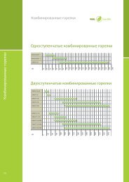
Legenda attacchi<br />
Coupling key<br />
Pos.<br />
Descrizione/Description<br />
1 Mandata e ritorno impianto e circuito primario<br />
Plant and primary circuit delivery and return<br />
2 Ausiliario/Auxiliary circuit<br />
3 Resistenza elettrica integrativa<br />
Additional resistor<br />
4 Termostato resistenza elettrica<br />
Resistor thermostat<br />
5 Portasonda/Probe holder<br />
6 Circuiti bassa tem<strong>per</strong>atura/Low tem<strong>per</strong>ature circuit<br />
7 Scarico/Drain<br />
8 Sfiato/Pressure relief valve
019<br />
K<br />
A<br />
B<br />
E<br />
H tot<br />
C<br />
F<br />
I<br />
Di<br />
d<br />
8<br />
1<br />
4<br />
1<br />
2<br />
5<br />
5<br />
6<br />
4<br />
6<br />
2<br />
1<br />
3<br />
1<br />
7<br />
Tabella Dimensioni/Size Table<br />
Capacità<br />
Capacity<br />
(mm) Di d Htot A B C E F I K<br />
100 500 400 975 285 445 605 795 - - 124.5<br />
200 550 450 1365 320 580 850 1120 - - 125<br />
300 650 550 1450 325 425 1035 1185 635 835 130<br />
500 750 650 1735 375 685 1295 1445 780 980 135<br />
800 890 790 1785 395 685 1295 1445 820 1020 125<br />
1000 950 850 2050 410 950 1560 1710 950 1150 120<br />
1500 1100 1000 2185 500 1040 1650 1800 1020 1220 165<br />
2000 1200 1100 2505 505 1345 1955 2105 1180 1380 155<br />
Connessioni/Couplings<br />
Capacità<br />
Capacity<br />
(pollici/inches) 1 2 3 4 5 6 7 8<br />
100 1”1/2 1”1/2 2” 1/2” - - 1”1/4 1”<br />
200 1”1/2 1”1/2 2” 1/2” - - 1”1/4 1”<br />
300 2” 1”1/2 2” 1/2” 1/2” 1”1/2 1”1/4 1”<br />
500 3” 2” 2” 1/2” 1/2” 2” 1”1/4 1”<br />
750 3” 2” 2” 1/2” 1/2” 2” 1”1/4 1”<br />
1000 3” 2” 2” 1/2” 1/2” 2” 1”1/4 1”<br />
1500 3” 2” 2” 1/2” 1/2” 2” 1”1/4 1”<br />
2000 3” 2” 2” 1/2” 1/2” 2” 1”1/4 1”
020<br />
Termoaccumuli puffer compatti<br />
caldo-freddo<br />
Compact puffer hot-chilled water storage units<br />
A-AM-AMI<br />
Versioni/Models<br />
A<br />
AM<br />
AMI<br />
Solo serbatoio inerziale<br />
Only inertial tank<br />
Con kit idronico completo di valvola<br />
miscelatrice e pompa di circolazione<br />
With hydronic kit equipe with mixing<br />
valve and circulation pump<br />
Equipaggiato con una pompa di<br />
circolazione ad inverter <strong>per</strong><br />
massimizzare l’efficienza<br />
dell’impianto e la flessibilità<br />
d’installazione<br />
Equipped with an inverter circulation<br />
pump to maximise system efficieny<br />
and installation flexibility<br />
Modelli Codice/Part no.<br />
Models<br />
A-100 842020141X<br />
A-200 842020110X<br />
AM-100 838030055<br />
AM-200 838030061X<br />
AMI-100 838030062X<br />
AMI-200 838030063X<br />
Accumulo inerziale costituito da un serbatoio coibentato in<br />
acciaio, garantisce il contenuto idoneo di <strong>acqua</strong> nell’impianto<br />
<strong>per</strong> ottimizzarne il funzionamento e l’efficienza, come <strong>per</strong><br />
esempio con pompa di calore.<br />
Realizzato in lamiera zincata e verniciata è completamente<br />
pannellato ed estremamente compatto, adatto ad essere<br />
collocato posteriormente o a lato della macchina <strong>per</strong><br />
consentire il minimo ingombro.<br />
Disponibile in tre versioni con capacità da 100 o 200 litri,<br />
completo di sfiato automatico, pozzetto porta sonda e<br />
supporti in gomma.<br />
System inertial storage device consisting of a steel insulated<br />
tank ensures the adequate water content in the system to<br />
optimize plant o<strong>per</strong>ation and efficiency, for example with a<br />
heat pump system.<br />
Made of painted galvanized steel sheet, it is fully paneled and<br />
extremely compact. It can be placed either at the back or on<br />
the side of the machine to ensure minimal overall dimensions.<br />
Available in three versions with a 100 or 200 litre capacity equipped with automatic air vent,<br />
probe pit and rubber supports.<br />
A<br />
A<br />
D<br />
B<br />
F G H I<br />
Dimensioni/Dimensions<br />
E<br />
E<br />
C<br />
E<br />
D<br />
F<br />
M<br />
L<br />
K<br />
G H<br />
Mod. A (mm) B (mm) C (mm) Connessioni/Connections<br />
100 1225 605<br />
J<br />
240 1” M<br />
E<br />
200 1225 605 440 1” M<br />
B<br />
C
021<br />
Mod. A<br />
6<br />
1<br />
9<br />
7<br />
4<br />
5<br />
1<br />
5<br />
6<br />
3<br />
Legenda attacchi<br />
Coupling key<br />
7<br />
7<br />
1 Serbatoio<br />
Tank<br />
5<br />
2 Circolatore (ad 2 inverter <strong>per</strong> AMI)<br />
Circulator (inverter type for 1 AMI version)<br />
4 6<br />
3 Pozzetto porta sonda 4<br />
Probe pit<br />
6<br />
4 Sfiato automatico serbatoio<br />
Automatic tank air vent<br />
5 Valvola miscelatrice<br />
Mixing Valve<br />
8<br />
8<br />
6 Pannello laterale amovibile<br />
Removable side panel<br />
7 Co<strong>per</strong>chio serbatoio<br />
Tank cover rain<br />
Mod. AM/AMI 100<br />
9<br />
7<br />
4<br />
5<br />
1<br />
5<br />
6<br />
3<br />
7<br />
2<br />
4<br />
6<br />
7<br />
5<br />
1<br />
6<br />
4<br />
8 Scarico<br />
Drain<br />
9 Sportellino amovibile<br />
Removable door<br />
2<br />
3<br />
6<br />
8<br />
Mod. AM/AMI 200<br />
7<br />
7<br />
5<br />
6<br />
2<br />
4<br />
6<br />
5<br />
1<br />
6<br />
4<br />
2<br />
3<br />
6<br />
8
022<br />
Ricambi - supplementi<br />
accessori<br />
Spare parts – ancillary parts - accessories<br />
Resistenze elettriche<br />
Electrical heaters<br />
Potenza Tensione (V) Numero Diametro Lunghezza Codice<br />
elettrica elementi attacchi<br />
Wattage Voltage (V) No. of Coupling Length Part.no<br />
elements diameter<br />
* Dotati di termostato di regolazione<br />
incorporato. Protezione IP 40<br />
Per i modelli a 3 elementi sono disponibili<br />
protezioni IP 55<br />
* Complete with built-in adjustment<br />
thermostat. IP 40 protection rating<br />
IP 55 protection rating is available for<br />
3-element models.<br />
Protezione IP 55 attacco 1”1/4 824100030<br />
Protezione IP 55 attacco 2” 824100031<br />
IP 55 protection, 1¼” coupling 824100030<br />
IP 55 protection, 2” coupling 824100031<br />
1200* 230 1 1” 1/4 220 824100003<br />
1500* 230 1 1” 1/4 290 824100004<br />
2000* 230 1 1” 1/4 330 824100005<br />
1300 230/380 3 2” 220 824100008<br />
2000 230/380 3 2” 290 824100009<br />
2000 230/380 3 1” 1/4 300 824100053<br />
3000 230/380 3 2” 340 824100010<br />
3000 230/380 3 1” 1/4 300 824100011<br />
4000 230/380 3 2” 390 824100012<br />
4000 230/380 3 1” 1/4 400 824100072<br />
5000 230/380 3 2” 500 824100013<br />
5000 230/380 3 1” 1/4 450 824100073<br />
6000 230/380 3 2” 600 824100014<br />
7000 230/380 3 2” 580 824100015<br />
8000 230/380 3 2” 620 824100016<br />
10000 230/380 3 2” 770 824100017<br />
Codice/Part no.<br />
Descrizione/Description<br />
824100001 Resistenza antigelo 200W<br />
200W antifreeze heater
023<br />
Descrizione/Description<br />
Codice/Part no.<br />
Termometro <strong>per</strong> <strong>acqua</strong> calda 822050001<br />
Hot water thermometer<br />
Termometro <strong>per</strong> <strong>acqua</strong> fredda 822050004<br />
Cold water thermometer<br />
Descrizione/Description<br />
Codice/Part no.<br />
Termostato 822050004<br />
Thermostat<br />
Descrizione/Description<br />
Codice/Part no.<br />
Bitermostato 822050006<br />
Double thermostat<br />
Descrizione/Description<br />
Codice/Part no.<br />
Bitermostato antigelo 822050007<br />
Antifreeze double thermostat
Fiorini Industries S.r.l.<br />
Via Co<strong>per</strong>nico, 81/85<br />
47122 - Forlì - ITALY<br />
Tel. +39 0543 723197 - Fax +39 0543 720413<br />
comm@fiorinigroup.it - www.fiorinigroup.it