Manual - Online USV Systeme
Manual - Online USV Systeme
Manual - Online USV Systeme

You also want an ePaper? Increase the reach of your titles
YUMPU automatically turns print PDFs into web optimized ePapers that Google loves.
<strong>Manual</strong><br />
XANTO RT-Series<br />
RT 1000<br />
RT 2000<br />
RT 3000<br />
www.online-ups.com
Benutzerhandbuch<br />
ONLINE XANTO RT-Serie<br />
Version: 16. August 2010<br />
Deutsch: Seite 1 - 42<br />
English: Page 43 - 84<br />
Italia: Pagina 85 - 128<br />
Deutschland Italien Schweiz<br />
ONLINE <strong>USV</strong>-<strong>Systeme</strong> AG<br />
Dreimühlenstraße 4<br />
D-80469 München<br />
Phone +49 (89) 2423990-10<br />
Fax +49 (89) 2423990-20<br />
www.online-usv.de<br />
ONLINE UPS-Systems S.r.l.<br />
Via Edison 12<br />
I-20058 Villasanta (Milano)<br />
Phone +39 (039) 2051444<br />
Fax +39 (039) 2051435<br />
www.online-ups.it<br />
ONLINE <strong>USV</strong>-<strong>Systeme</strong> AG<br />
Eigenheimstraße 11<br />
CH-8304 Wallisellen (Zürich)<br />
Phone +41 (44) 9452829<br />
Fax +41 (44) 9453288<br />
www.online-usv.ch<br />
Seite 1 von 128
Seite 2 von 128
1. Inhalt<br />
1. Inhalt................................................................................3<br />
2. Abbildungsverzeichnis ..................................................5<br />
3. Tabellenverzeichnis........................................................6<br />
4. Einleitung ........................................................................7<br />
5. Sicherheitshinweise .......................................................8<br />
6. Produktbeschreibung...................................................12<br />
6.1 Ausstattungsmerkmale ............................................12<br />
6.2 Systemkomponenten...............................................12<br />
6.2.1 Steuereinheit ...........................................................13<br />
6.2.2 Batteriepaket ...........................................................18<br />
7. Funktionsprinzip...........................................................20<br />
7.1 Leistungselektronik..................................................20<br />
7.2 Schnittstellenanschlüsse .........................................21<br />
7.2.1 RS-232-Protokoll .....................................................22<br />
7.2.2 Potentialfreie Kontakte.............................................22<br />
7.2.3 Slot für optionale Schnittstellenkarten......................23<br />
8. Installation.....................................................................24<br />
8.1 Tower-Installation ....................................................25<br />
8.1.1 <strong>USV</strong> Single-Tower-Installation.................................25<br />
8.1.2 <strong>USV</strong> plus Batteriepaket-Installation .........................26<br />
8.2 Rack-Installation......................................................27<br />
8.3 Software-Installation ................................................27<br />
9. Betrieb ...........................................................................28<br />
9.1 Betriebsarten ...........................................................28<br />
9.2 Einschalten..............................................................29<br />
9.2.1 Normaler Start (Eingangsspannung vorhanden).....29<br />
9.2.2 Kaltstart (Stromausfall) ............................................30<br />
9.3 Ausschalten.............................................................30<br />
9.3.1 Ausschalten im Normalbetrieb.................................30<br />
9.3.2 Ausschalten im Batteriebetrieb ................................31<br />
9.3.3 Ausschalten im Bypassbetrieb.................................31<br />
9.4 Batterietest ..............................................................31<br />
Seite 3 von 128
10. Wartung, Fehler beheben.............................................33<br />
10.1 Lagerung .................................................................33<br />
10.2 Batteriewartung .......................................................33<br />
10.3 Wechseln der Ausgangssicherung ..........................34<br />
10.4 Funktionsüberprüfung..............................................35<br />
10.5 Fehlersuche.............................................................36<br />
11. Technische Daten.........................................................38<br />
11.1 Abmessungen, Gewicht...........................................38<br />
11.2 Elektrische Spezifikationen......................................38<br />
11.3 Umgebungsbedingungen.........................................40<br />
11.4 Zertifizierungen........................................................41<br />
12. Garantie.........................................................................42<br />
Seite 4 von 128
2. Abbildungsverzeichnis<br />
Abbildung 1: Vorderseite XANTO RT-Serie 13<br />
Abbildung 2: Bedien- und Anzeigeelemente 14<br />
Abbildung 3: Rückseite XANTO RT 1000 17<br />
Abbildung 4: Rückseite XANTO RT 2000 18<br />
Abbildung 5: Rückseite XANTO RT 3000 18<br />
Abbildung 6: Vorderansicht Batteriepaket 19<br />
Abbildung 7: Rückseite XANTO RT Batteriepaket 19<br />
Abbildung 8: Blockschaltbild 20<br />
Abbildung 9: Bodenplatte für Towermontage 25<br />
Abbildung 10: Positionierung der <strong>USV</strong> 25<br />
Abbildung 11: Bodenplatte mit Verlängerung 26<br />
Abbildung 12: Anschluss Batteriepakete 26<br />
Abbildung 13: Hot-Swap-Batterie bei XANTO RT 1000 34<br />
Seite 5 von 128
3. Tabellenverzeichnis<br />
Tabelle 1: Bedienelemente 15<br />
Tabelle 2: Anzeigeelemente 15<br />
Tabelle 3: Fehlercodes<br />
(LED-Anzeige und akustische Signale) 16<br />
Tabelle 4: Batterietypen 18<br />
Tabelle 5: Überbrückungszeit mit zusätzlichen Batteriepaketen<br />
(BP = Batteriepaket) 19<br />
Tabelle 6: Pinbelegung der RS-232-Schnittstelle 22<br />
Tabelle 7: Pinbelegung der Schnittstelle (DB9-Buchse) 23<br />
Tabelle 8: Übersicht Schnittstellenzubehör 23<br />
Tabelle 9: Lieferumfang 24<br />
Tabelle 10: Fehlersuche 37<br />
Tabelle 11: Abmessungen, Gewicht 38<br />
Tabelle 12: Elektrische Spezifikationen 40<br />
Tabelle 13: Umgebungsbedingungen 40<br />
Tabelle 14: Zertifizierungen 41<br />
Seite 6 von 128
4. Einleitung<br />
Die ONLINE <strong>USV</strong>-<strong>Systeme</strong> AG gehört zu den führenden Herstellern<br />
von unterbrechungsfreien Stromversorgungen (<strong>USV</strong>).<br />
Seit 1988 beschäftigt sich das deutsche Unternehmen mit<br />
Entwicklung, Fertigung, Vertrieb und Support von <strong>USV</strong>-<br />
<strong>Systeme</strong>n. Nach verkauften Stückzahlen sind deren Produkte<br />
die deutsche Nummer Eins im <strong>USV</strong>-Markt und wegen ihrer<br />
hohen Qualität und des exzellenten Supports international<br />
anerkannt.<br />
Die ONLINE XANTO RT-Serie ist eine unterbrechungsfreie<br />
Stromversorgung (<strong>USV</strong>) in Doppelwandlertechnologie; Klassifizierung<br />
VFI-SS-111. Sie ist der perfekte Schutz für alle unternehmensrelevanten<br />
Datenverarbeitungs- und Telekommunikations-Anwendungen.<br />
Stromausfälle, Spannungsschwankungen<br />
und Überspannung, die Server und andere elektronischen<br />
Geräte beschädigen können, werden somit verhindert.<br />
Das Doppelwandlerprinzip eliminiert alle Netzstörungen. Ein<br />
Gleichrichter wandelt den Wechselstrom aus der Steckdose<br />
(Eingangsspannung) in Gleichstrom. Dieser Gleichstrom lädt<br />
die Batterien und speist den Wechselrichter. Der Wechselrichter<br />
wiederum erzeugt aus dem Gleichstrom einen neuen Sinus-Wechselstrom,<br />
mit dem die Verbraucher permanent versorgt<br />
werden (Ausgangsspannung).<br />
Rechner und Peripherie werden so völlig unabhängig von der<br />
Eingangsspannung versorgt. Bei Stromausfall versorgen die<br />
wartungsfreien Batterien den Wechselrichter. Die bei anderen<br />
<strong>Systeme</strong>n unvermeidbaren Umschaltzeiten von Netz- auf Batteriebetrieb<br />
sind durch den gleitenden Übergang ausgeschlossen.<br />
Änderungen oder Modifizierungen an diesem Gerät,<br />
die nicht ausdrücklich von der für den standardgemäßen<br />
Betrieb des Geräts verantwortlichen Stellen<br />
genehmigt wurden, können das Erlöschen des Garantieanspruchs<br />
zur Folge haben.<br />
Seite 7 von 128
5. Sicherheitshinweise<br />
VOR INSTALLATION UND INBETRIEBNAHME DAS BE-<br />
NUTZERHANDBUCH UND DIE SICHERHEITSHINWEISE<br />
AUFMERKSAM LESEN UND BEACHTEN!<br />
Transport<br />
• <strong>USV</strong>-Anlage nur in der Originalverpackung transportieren<br />
(Schutz gegen Stoß und Schlag).<br />
Aufstellung<br />
Aufgrund ihres Gewichtes werden für die Installation der <strong>USV</strong><br />
zwei Personen benötigt.<br />
Dieses Gerät ist für die Installation in einem temperaturkontrollierten<br />
Raum, frei von leitfähigen verunreinigten Substanzen<br />
bestimmt. Spezifizierungen zu den Umgebungsbedingungen<br />
finden Sie in Kapitel 11.3.<br />
• Wird die <strong>USV</strong>-Anlage aus kalter Umgebung in den Arbeitsraum<br />
gebracht, kann Betauung auftreten. Vor Inbetriebnahme<br />
muss die <strong>USV</strong>-Anlage absolut trocken sein. Deshalb<br />
eine Akklimatisationszeit von mindestens zwei Stunden<br />
abwarten.<br />
• <strong>USV</strong>-Anlage nicht in der Nähe von Wasser oder in feuchter<br />
Umgebung aufstellen.<br />
• <strong>USV</strong>-Anlage nicht in direktem Sonnenlicht oder in der Nähe<br />
von Wärmequellen aufstellen.<br />
• Lüftungsöffnungen im Gehäuse der <strong>USV</strong>-Anlage nicht blockieren.<br />
Seite 8 von 128
Anschluss / Elektrische Sicherheit<br />
• Nie allein unter gefährlichen Bedingungen arbeiten.<br />
• Stellen Sie den einwandfreien Zustand der Stecker, Steckdosen<br />
und Eingangskabel sicher.<br />
• <strong>USV</strong>-Anlage nur an einer geerdeten Schutzkontaktsteckdose<br />
anschließen.<br />
• Max. Stromaufnahme und ausreichende Absicherung der<br />
Hausinstallation beachten.<br />
• Die Steckdose der Hausinstallation (Schutzkontaktsteckdose)<br />
muss leicht zugänglich sein und sich in der Nähe der<br />
<strong>USV</strong>-Anlage befinden.<br />
• Nur VDE-geprüfte und CE-gekennzeichnete Verbindungsleitungen<br />
verwenden.<br />
• Gemäß EMC-Richtlinie darf das an die <strong>USV</strong> angeschlossene<br />
Ausgangskabel nicht länger als 10m sein.<br />
• Keine Haushaltsgeräte, wie beispielsweise Haartrockner,<br />
an den <strong>USV</strong>-Ausgangssteckdosen anschließen.<br />
• Keine Geräte an den <strong>USV</strong>-Ausgangssteckdosen anschließen,<br />
die die <strong>USV</strong>-Anlage überlasten (z. B. Laserdrucker).<br />
• Leitungen so verlegen, dass niemand darauf treten oder<br />
darüber stolpern kann.<br />
Betrieb<br />
• Netzkabel während des Betriebs nicht von der <strong>USV</strong>-Anlage<br />
oder der Steckdose der Hausinstallation (Schutzkontaktsteckdose)<br />
abziehen, da sonst die Schutzerdung der <strong>USV</strong>-<br />
Anlage und aller angeschlossenen Verbraucher aufgehoben<br />
wird.<br />
• Die <strong>USV</strong>-Anlage verfügt über eine eigene, interne Stromquelle<br />
(Batterien). Die <strong>USV</strong>-Ausgangssteckdosen können<br />
stromführend sein, selbst wenn die <strong>USV</strong>-Anlage nicht an<br />
die Steckdose bzw. an die Einspeisung der Hausinstallation<br />
angeschlossen ist.<br />
Seite 9 von 128
• Zum völligen Abschalten der <strong>USV</strong>-Anlage die OFF-Taste<br />
für min. 2 Sek. drücken und dann das Netzkabel ziehen.<br />
• Darauf achten, dass keine Flüssigkeit oder sonstigen<br />
Fremdkörper in die <strong>USV</strong>-Anlage gelangen.<br />
Wartung, Service, Störungen<br />
• Die <strong>USV</strong>-Anlage enthält Spannungen, die gefährlich sind.<br />
Reparaturen sind grundsätzlich nur von qualifiziertem Wartungspersonal<br />
durchzuführen.<br />
• Außer der Batterie enthält diese Einheit keine vom Benutzer<br />
auszutauschenden Teile.<br />
• Achtung - Gefahr von Stromschlägen. Selbst nach Trennung<br />
vom Stromversorgungsnetz (Steckdose) bleiben Bauteile<br />
innerhalb der <strong>USV</strong>-Anlage an die Batterien angeschlossen<br />
und befinden sich unter gefährlichem Spannungspotential.<br />
Vor der Durchführung von Service- und<br />
Wartungsarbeiten Batterieversorgungskreis trennen und<br />
Spannungsfreiheit überprüfen.<br />
• Das Auswechseln der Batterien ist durch Personal mit<br />
Sachkenntnis über Batterien und Kenntnis über die geforderten<br />
Vorsichtsmaßnahmen durchzuführen und zu überwachen.<br />
Unbefugte Personen sind von den Batterien fernzuhalten.<br />
• Achtung - Gefahr von Stromschlägen. Der Batteriestromkreis<br />
ist von der Eingangsspannung nicht getrennt. Zwischen<br />
den Batterieanschlüssen und der Erde können gefährliche<br />
Spannungen auftreten.<br />
• Batterien können Stromschlag verursachen und weisen<br />
einen hohen Kurzschlussstrom auf. Bei Arbeiten mit Batterien<br />
sind u. a. folgende Vorsichtsmaßregeln zu beachten:<br />
- Armbanduhren, Ringe oder andere Metallgegenstände<br />
entfernen.<br />
- Nur Werkzeuge mit isolierten Griffen verwenden.<br />
• Beim Austauschen der Batterien dieselbe Anzahl und denselben<br />
Batterietyp verwenden.<br />
Seite 10 von 128
• Batterien nicht ins Feuer werfen, die Batterien könnten<br />
explodieren.<br />
• Batterien nicht öffnen oder zerstören. Freigesetztes Elekrolyt<br />
ist schädlich für Haut und Augen. Es kann giftig sein.<br />
• Zum Schutz vor einem Brand darf die Sicherung nur durch<br />
einen gleichen Typ mit gleichem Nennwert ersetzt werden.<br />
• <strong>USV</strong>-Anlage nicht auseinanderbauen.<br />
Seite 11 von 128
6. Produktbeschreibung<br />
XANTO RT ist eine intelligente ONLINE-<strong>USV</strong> (Güteklasse 1,<br />
Klassifikation VFI-SS-111) mit höchster Systemverfügbarkeit.<br />
Sie versorgt die angeschlossenen, sensiblen Geräte mit perfekter<br />
Sinus-Wechselspannung und schützt diese hiermit vor<br />
Stromausfall und Spannungsschwankungen.<br />
Das spezielle Produktdesign bietet vielfältige Einsatzmöglichkeiten.<br />
Je nach Kundenanforderung sowohl als Tower /<br />
Standgerät als auch liegend im Rack. Ideal für Anwendungen<br />
mit nur geringer Stellfläche wie beispielsweise Telekommunikationseinrichtungen,<br />
Serverräume usw.<br />
6.1 Ausstattungsmerkmale<br />
• Nur 2 HE Bauhöhe.<br />
• Hot-Swap-Batterie.<br />
• XANTO RT 3000 mit Ausgangsklemmenanschluß.<br />
• Außergewöhnlich hohe Leistung, Wirkungsgrad >88%.<br />
• Sehr geringe Geräuschentwicklung (max. 43dB) durch<br />
geregelte Lüfter.<br />
• Hohe Systemverfügbarkeit, Selbstüberwachung und Fehlerdiagnose<br />
durch fortschrittliche DSP-Technologie.<br />
• Große Eingangsspannungstoleranz mit unempfindlichem<br />
Ausgang gegenüber Störungen der Eingangsspannung.<br />
Passend für alle Anwendungsbereiche mit nicht konstanter<br />
Energieversorgung.<br />
• Große Eingangsfrequenz-Toleranz. Ideal zum Betrieb nach<br />
Generatoren.<br />
6.2 Systemkomponenten<br />
XANTO RT besteht aus den beiden Grundelementen Steuereinheit<br />
und Batteriepaket.<br />
Erstere ist für die Leistungsübertragung verantwortlich, vergleichbar<br />
mit dem Motor eines Kraftfahrzeuges und stellt die<br />
Ausgangsspannung für die Last zur Verfügung. Darüber hinaus<br />
kontrolliert und lädt die Steuereinheit die Batterie. Das<br />
Seite 12 von 128
Batteriepaket versorgt bei Stromausfall die <strong>USV</strong> mit Gleichspannung,<br />
vergleichbar mit dem Tank eines Kraftfahrzeuges.<br />
6.2.1 Steuereinheit<br />
Es gibt drei Modelle der Steuereinheit:<br />
• 1kVA mit interner Batterie, keine Möglichkeit zur Erweiterung<br />
der Überbrückungszeit.<br />
• 2kVA Steuereinheit ohne interne Batterie. Externes Batteriepaket<br />
zum Betrieb notwendig. Verlängerte Überbrückungszeit<br />
durch Parallelbetrieb mehrerer Batteriepakete<br />
möglich.<br />
• 3kVA Steuereinheit ohne interne Batterie. Externes Batteriepaket<br />
zum Betrieb notwendig. Verlängerte Überbrückungszeit<br />
durch Parallelbetrieb mehrerer Batteriepakete<br />
möglich.<br />
6.2.1.1 Gerätevorderseite:<br />
Alle Steuereinheiten haben die gleiche Vorderseite. Diese<br />
stellt Bedien- und Anzeigeelemente zur Verfügung.<br />
Bedienelemente sind die ON- und OFF-Taste, Anzeigeelemente<br />
die Leuchtdioden.<br />
Abbildung 1: Vorderseite XANTO RT-Serie<br />
Seite 13 von 128
6.2.1.2 Bedien- und Anzeigeelemente:<br />
Abbildung 2: Bedien- und Anzeigeelemente<br />
Bedienelemente:<br />
Taste<br />
ON-Taste<br />
Funktion<br />
ON / Alarm-AUS-Taste:<br />
Die ON / Alarm-Aus-Taste ermöglicht drei<br />
Funktionen:<br />
1.) <strong>USV</strong> / Wechselrichter einschalten:<br />
Drücken der ON-Taste bis ein akustisches<br />
Signal ertönt (ca. 1–2 Sek.) und<br />
die <strong>USV</strong> schaltet in den Normalbetrieb.<br />
2.) Alarm AN / AUS (im Batteriebetrieb):<br />
Im Batteriebetrieb ertönt alle 3 Sek. ein<br />
akustisches Signal. Drücken Sie die<br />
ON-Taste bis ein akustisches Signal ertönt<br />
(ca. 1-2 Sek.). Anschließend ist das<br />
period. Signal inaktiv. Zum Aktivieren<br />
drücken Sie die ON-Taste erneut bis<br />
ein akust. Signal ertönt (ca. 1-2 Sek.).<br />
Seite 14 von 128
OFF-Taste<br />
3.) Batterietest aktivieren (im Normalbetrieb):<br />
Halten Sie die ON-Taste gedrückt bis<br />
ein akustisches Signal ertönt (ca. 1–2<br />
Sek.)<br />
Die OFF-Taste hat 2 Funktionen:<br />
1.) Wechselrichter Ausschalten:<br />
Drücken Sie im Normal- oder Batteriebetrieb<br />
die OFF-Taste (ca. 1–2 Sek.)<br />
und der Wechselrichter schaltet aus.<br />
Die Ausgangssteckdosen sind jetzt<br />
spannungsfrei.<br />
2.) Bereitschaftsbetrieb:<br />
Drücken Sie im Bypassbetrieb die<br />
OFF-Taste (ca. 1–2 Sek.) und die <strong>USV</strong><br />
schaltet den Ausgang spannungsfrei.<br />
Tabelle 1: Bedienelemente<br />
Anzeigeelemente:<br />
Die Bedeutung der Leuchtdioden-Anzeige ist in der nachfolgenden<br />
Tabelle beschrieben:<br />
BATTERY-LED<br />
(grün)<br />
INVERTER-LED<br />
(grün)<br />
BYPASS-LED<br />
(grün)<br />
LINE-LED<br />
(grün)<br />
ALARM-LED (rot)<br />
<strong>USV</strong>-Betrieb / Batteriebetrieb und<br />
Batteriespannung innerhalb der<br />
Toleranz (Dauerlicht).<br />
LED-Blinken: Fehlerhafte Batterie<br />
oder zu hohe Ladespannung.<br />
Normalbetrieb / Wechselrichterbetrieb<br />
(Dauerlicht).<br />
LED-Blinken: Fehlerhafter Wechselrichter.<br />
Bypassbetrieb.<br />
ACHTUNG: Die Last wird nicht<br />
batteriegepuffert versorgt!!!<br />
Netzspannung in Toleranz.<br />
Bei Stromausfall erlischt diese LED.<br />
Fehler, bspw. Überlast.<br />
Tabelle 2: Anzeigeelemente<br />
Seite 15 von 128
Die Kombination von LED-Anzeige und akustischem Signal<br />
beschreibt einen der nachfolgend definierten Zustände (siehe<br />
auch Kap.10.5):<br />
Betriebsart LED-Anzeige Signalton<br />
1<br />
2<br />
3<br />
4<br />
5<br />
Alarm<br />
Line<br />
Bypass<br />
Inverter<br />
Battery<br />
0 – 25% • • • Kein<br />
Normalbetrieb<br />
(Last)<br />
26 – 50% • • • • kein<br />
51 – 75% • • • • • Kein<br />
76 – 100% • • • • • • Kein<br />
101 – 105% • • • • • • • Kein<br />
> 105% • • • • • • • 2x / Sek.<br />
0 – 25% • • • 1x / Sek.<br />
Batteriebetrieb<br />
(Kapazität)<br />
26 – 50% • • • • 1x / 3 Sek.<br />
51 – 75% • • • • • 1x / 3 Sek.<br />
76 – 95% • • • • • • 1x / 3 Sek.<br />
>96% • • • • • • • 1x / 3 Sek.<br />
Kurzschluss • • Dauernd<br />
Ladegerät-Fehler • • Dauernd<br />
Übertemperatur • • Dauernd<br />
Lüfter-Fehler • • 1x / Sek.<br />
Gleichrichter-Fehler • • Dauernd<br />
Wechselrichter-Fehler • Dauernd<br />
Überlast • • • • • • Dauernd<br />
Batterie defekt (Normalbetrieb)<br />
Batterie defekt<br />
(Bereitschaftsbetrieb)<br />
• • Kein<br />
Kein<br />
Keine Batterie • 6x<br />
• = EIN = von weiterem Betriebszustand abhängig = Blinken<br />
Tabelle 3: Fehlercodes (LED-Anzeige und akustische Signale)<br />
Seite 16 von 128
ACHTUNG:<br />
LED 5 = gelb,<br />
ALARM-LED = rot,<br />
alle anderen = grün<br />
6.2.1.3 Geräterückseite:<br />
Die Rückseiten der Steuereinheiten sind unterschiedlich.<br />
Die Rückseite verfügt über:<br />
• Eingangssteckdose, ausgeführt als Kaltgerätestecker<br />
(männlich/male).<br />
• Überstromschutzeinrichtung.<br />
• Ausgangssteckdosen ausgeführt als 10A Kaltgerätebuchse<br />
sowie Klemmenblock bei 3kVA-Steuereinheit.<br />
• Anschlussbuchse für externes Batteriepaket (nicht 1kVA-<br />
Steuereinheit).<br />
• DB9-Buchse (männlich/male) für RS-232-Kommunikation<br />
und potentialfreie Kontakte.<br />
• Slot für optionale Schnittstellenkarten (SNMP- / Netzwerkmanagementkarte<br />
basic, SNMP- / Netzwerkmanagementkarte<br />
professionell, USB-Karte).<br />
Abbildung 3: Rückseite XANTO RT 1000<br />
Seite 17 von 128
Abbildung 4: Rückseite XANTO RT 2000<br />
Abbildung 5: Rückseite XANTO RT 3000<br />
6.2.2 Batteriepaket<br />
Das Batteriepaket ist in zwei unterschiedlichen Versionen<br />
verfügbar. Die Abmessungen sowie Beschaffenheiten von<br />
Vorder- und Rückansicht sind jedoch identisch:<br />
Bezeichnung<br />
XANTO RT 2000 Batteriepaket<br />
XANTO RT 3000 Batteriepaket<br />
Eigenschaften<br />
6x 12V / 7,2Ah Batterie<br />
6x 12V / 9,0Ah Batterie<br />
Tabelle 4: Batterietypen<br />
Seite 18 von 128
6.2.2.1 Batteriepaket Vorder- und Rückansicht:<br />
Abbildung 6: Vorderansicht XANTO RT Batteriepaket<br />
Abbildung 7: Rückseite XANTO RT Batteriepaket<br />
Die Wahl der Buchse für Ein- oder Ausgang ist beliebig!<br />
Die verlängerte Überbrückungszeit bei optionaler Parallelschaltung<br />
mehrerer Batteriepakete kann der nachfolgenden<br />
Tabelle entnommen werden. Es wird dringend empfohlen die<br />
max. Anzahl an Batteriepaketen nicht zu überschreiten:<br />
Modell<br />
Standard<br />
Überbrückungszeit (Min.)<br />
bei 50% / 100% Last<br />
+ 1 BPs + 2 BPs + 3 BPs + 4 BPs<br />
XANTO RT 1000 18 / 6 - - - -<br />
XANTO RT 2000 - 17 / 6 52 / 20 94 / 37 122 / 54<br />
XANTO RT 3000 - 12 / 5 37 / 16 55 / 26 78 / 40<br />
Tabelle 5: Überbrückungszeit mit zusätzlichen Batteriepaketen<br />
(BP = Batteriepaket)<br />
Seite 19 von 128
7. Funktionsprinzip<br />
7.1 Leistungselektronik<br />
Die XANTO RT-Serie besteht im Wesentlichen aus den im<br />
nachfolgenden Blockschaltbild dargestellten Modulen:<br />
Abbildung 8: Blockschaltbild<br />
Ein DSP (Digital Signal Prozessor) verarbeitet im Signalweg<br />
die Informationen über die Stromqualität und setzt diese im<br />
Leistungskreis mit IGBT-Modulen (Insulated Gate Bipolar<br />
Transistor) um. Hierdurch wird die herausragende Qualität der<br />
XANTO RT-Serie gewährleistet.<br />
Die Funktion der einzelnen Module ist im Nachfolgenden kurz<br />
erläutert:<br />
• Netzeingang mit Eingangsfilter (EMI und Class D SPD):<br />
Filterung der Eingangsspannung zum Schutz der nachgeschalteten<br />
sensiblen Elektronik vor Störungen wie bspw.<br />
Überspannung.<br />
• Gleichrichter mit PFC (Power Factor Correction):<br />
Transformiert die Eingangsspannung in Gleichspannung<br />
zur Versorgung der Batterie und des Wechselrichters.<br />
• DC/DC-Konverter:<br />
Hebt die 12V-Gleichspannung der Batterie auf ideale Betriebsspannung<br />
des Wechselrichter an.<br />
Seite 20 von 128
• Wechselrichter:<br />
Im Normalbetrieb wandelt er die Gleichspannung des<br />
Gleichrichters in präzise Wechselspannung zur Versorgung<br />
der Last mit konstant 230V, 50Hz. Im Batteriebetrieb wird<br />
der Wechselrichter aus der Batterie versorgt.<br />
• Bypass:<br />
Im Fehlerfall, bspw. Übertemperatur oder Überlast schützt<br />
der Bypass die interne Elektronik vor Zerstörung. Im Fehlerfall<br />
wird die Lastversorgung autom. auf Bypassbetrieb<br />
geschaltet und die Verbraucher OHNE Batteriepufferung<br />
aus dem regulären Haus-Stromnetz versorgt. Dieser Betriebszustand<br />
wird über die Frontpanel-Anzeige sowie als<br />
Information über die Software signalisiert.<br />
• Ladegerät:<br />
Das interne Ladegerät versorgt die Batterien im Ladezustand<br />
mit einer konstanten Stromstärke von 1A.<br />
• Batterie / Akku:<br />
Wartungsfreier, verschlossener Blei-Gel-Akku.<br />
7.2 Schnittstellenanschlüsse<br />
Die XANTO RT-Serie verfügt an der Rückseite der <strong>USV</strong>-<br />
Anlage über einen DB9-Port als auch über einen Slot für optionale<br />
Schnittstellenkarten. An beiden können Computer angeschlossen<br />
werden.<br />
Die DB9-Buchse unterstützt die Kommunikation über das RS-<br />
232-Protokoll sowie potentialfreie Kontakte.<br />
Diese Anschlüsse ermöglichen<br />
• Überwachung der <strong>USV</strong>-Anlage,<br />
• Überwachung der Eingangsspannung,<br />
• Automatische Sicherung von Daten,<br />
• Abschaltung des Computers und<br />
• Abschaltung der <strong>USV</strong>-Anlage.<br />
Die Funktionen werden von der im Lieferumfang enthaltenen<br />
DataWatch-Software unterstützt.<br />
Seite 21 von 128
7.2.1 RS-232-Protokoll<br />
Pin<br />
2 TxD Gesendete Daten transmitted data<br />
3 RxD Empfangene Daten Received data<br />
5 GND Masse ground<br />
Tabelle 6: Pinbelegung der RS-232-Schnittstelle<br />
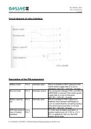
7.2.2 Potentialfreie Kontakte<br />
Pin-Beschreibung<br />
Potentialfreie Ausgänge (Pin 1 & 7, 8 & 9) *<br />
Potentialfreier Eingang (Pin 4 & 5) *<br />
* Max. Spannung / Stromstärke an Pins 1, 4, 5, 7, 8 und 9 ist 30V DC, 10mA<br />
Seite 22 von 128
Pin Beschreibung<br />
1 Batterie leer (open collector)<br />
2 <strong>USV</strong> TxD (typ. RS-232-level)<br />
3 <strong>USV</strong> RxD (typ. RS-232-level)<br />
4 Remote Inverter OFF 5-12V DC, 10-24mA<br />
(im Batteriebetrieb)<br />
5 GND<br />
6 -<br />
7 Batterie leer (open emitter)<br />
8 Batteriebetrieb (open emitter)<br />
9 Batteriebetrieb (open collector)<br />
Tabelle 7: Pinbelegung der Schnittstelle (DB9-Buchse)<br />
Bemerkungen:<br />
1.) Pin 1 & 7: Potentialfreier Ausgang. Bei normaler Batteriespannung<br />
geöffnet. Bei niedriger Batteriespannung geschlossen.<br />
2.) Pin 4 & 5: Potentialfreier Eingang. Bei Anlegen einer Hilfsspannung<br />
(5-12V DC) im Batteriebetrieb für min. 20 Sekunden<br />
schaltet die <strong>USV</strong> aus. Sonst keine Funktion.<br />
3.) Pin 8 & 9: Potentialfreier Ausgang. Bei Normalbetrieb geöffnet,<br />
bei Batteriebetrieb geschlossen.<br />
7.2.3 Slot für optionale Schnittstellenkarten<br />
XANTO RT ist mit einem Steckplatz für optionale Schnittstellenkarten<br />
ausgestattet. Mit diesem sind die nachfolgenden<br />
Produkte der ONLINE <strong>USV</strong>-<strong>Systeme</strong> AG kompatibel:<br />
Art.-Nr.<br />
DW5SNMP30<br />
DW7SNMP30<br />
PHXUSB<br />
Beschreibung<br />
Netzwerkmanagementkarte, professionell<br />
Netzwerkmanagementkarte, basic<br />
USB-Karte<br />
Tabelle 8: Übersicht Schnittstellenzubehör<br />
Seite 23 von 128
8. Installation<br />
1.) Überprüfen Sie den Verpackungskarton und den Inhalt auf<br />
Vollständigkeit und evtl. Schäden. Sollten Sie Schäden<br />
feststellen, informieren Sie sofort den Spediteur. Bewahren<br />
Sie die Verpackung für künftige Verwendungszwecke<br />
auf.<br />
Beschreibung<br />
Anzahl<br />
XANTO RT 1000<br />
XANTO RT 2000<br />
XANTO RT 3000<br />
XANTO RT 2000 Batteriepaket<br />
XANTO RT 3000 Batteriepaket<br />
19“-Montagewinkel 2 X X X X X<br />
Bodenplatte für Towermontage 2 X X X - -<br />
Bodenplatte, Verlängerung 2 - - - X X<br />
10A Kaltgeräteverlängerung 2 X X X - -<br />
16A Netzanschlußkabel 1 - - X - -<br />
Batteriekabel 1 - - - X X<br />
Schnittstellenkabel 1 X X X - -<br />
Software DataWatch 1 X X X - -<br />
Bedienungsanleitung 1 X X X - -<br />
Tabelle 9: Lieferumfang<br />
2.) Die <strong>USV</strong> wird durch interne Lüfter mit forciertem Luftstrom<br />
gekühlt. Gewährleisten Sie, dass min. 30cm Abstand hinter<br />
der <strong>USV</strong> zur Verfügung stehen.<br />
3.) Schließen Sie die <strong>USV</strong>-Anlage über ein VDE-geprüftes<br />
und CE-gekennzeichnetes Netzkabel an eine Schutzkontaktsteckdose<br />
der Hausinstallation an. Zum Anschluss der<br />
XANTO RT 3000 verwenden Sie das mitgelieferte Netzkabel.<br />
Seite 24 von 128
ACHTUNG:<br />
Die Ausgangssteckdosen der <strong>USV</strong> stehen nun<br />
unter Spannung. Dies wird durch die LINE- und<br />
BYPASS-LED signalisiert!<br />
8.1 Tower-Installation<br />
8.1.1 <strong>USV</strong> Single-Tower-Installation<br />
Bitte verwenden Sie die im Lieferumfang enthaltenen Bodenplatten.<br />
Entnehmen Sie diese dem Karton und fügen Sie sie<br />
wie nachfolgend abgebildet zusammen.<br />
Abbildung 9: Bodenplatte für Towermontage<br />
Nach dem Zusammenfügen der beiden separaten Komponenten<br />
bitte die <strong>USV</strong> wie folgt platzieren.<br />
Abbildung 10: Positionierung der <strong>USV</strong><br />
Seite 25 von 128
8.1.2 <strong>USV</strong> plus Batteriepaket-Installation<br />
Für alle <strong>USV</strong>-Anlagen der XANTO RT-Serie (Ausnahme XAN-<br />
TO RT 1000) sind zusätzliche Batteriepakete erhältlich.<br />
Zur Installation von <strong>USV</strong> und Batteriepaket bitte annähernd<br />
analog Kap. 8.1.1 verfahren.<br />
Für maximale Standfestigkeit die Verlängerung der Bodenplatte<br />
(liegt dem Batteriepaket bei) verwenden. Die Größe variiert<br />
nach Anzahl der zusätzlich verwendeten Batteriepakete.<br />
Abbildung 11: Bodenplatte mit Verlängerung<br />
Verwenden Sie das Batteriekabel (liegt dem Batteriepaket bei)<br />
um die <strong>USV</strong> mit dem Batteriepaket zu verbinden:<br />
Abbildung 12: Anschluss Batteriepakete<br />
1.) Trennen Sie die <strong>USV</strong>-Anlage<br />
vom Stromversorgungsnetz<br />
und die Verbraucher von der<br />
<strong>USV</strong>-Anlage.<br />
2.) Verbinden Sie das eine Ende<br />
des Batteriekabels mit dem<br />
Anschluß für die externe Batterie<br />
an der Rückseite der<br />
<strong>USV</strong> und das andere Ende<br />
mit einer beliebigen Buchse<br />
an der Rückseite des Batteriepaketes.<br />
HINWEIS:<br />
Bei Betrieb mit einem externen Batteriepaket<br />
verlängert sich der Ladevorgang auf 24 Stunden,<br />
bzw. auf 48 Stunden bei zwei Batteriepaketen<br />
nach Totalentladung.<br />
Seite 26 von 128
ACHTUNG:<br />
Die XANTO RT 2000 und XANTO RT 3000 haben<br />
keine internen Batterien. Zur einwandfreien Funktion<br />
muss die <strong>USV</strong> mit einem Batteriepaket verbunden<br />
werden!<br />
8.2 Rack-Installation<br />
Bei Installation in einem Rack muss ein standardisiertes<br />
19“-Rack mit einer Tiefe von mindestens 400mm verwendet<br />
werden. Bitte zur optimalen Gewichtsverteilung unsere optionalen<br />
Montageschienen Art.-Nr. „Rack-Kit“ oder schrankherstellerspezifische<br />
Montageschienen verwenden!<br />
1.) Verwenden Sie die im Lieferumfang enthaltenen Montagewinkel.<br />
2.) Entfernen Sie die M4x8-Schrauben an beiden Seitenteilen<br />
der <strong>USV</strong> (4 Stück je Seite).<br />
3.) Befestigen Sie die Montagewinkel mit den zuvor entfernten<br />
Schrauben.<br />
4.) Plazieren Sie die <strong>USV</strong> im Rack und fixieren Sie sie.<br />
8.3 Software-Installation<br />
Zur Installation der Shutdown-, Management- und Monitoringsoftware<br />
DataWatch beachten Sie bitte die separate Anleitung<br />
auf der CD.<br />
Seite 27 von 128
9. Betrieb<br />
1.) Laden Sie die Batterien vollständig auf, indem Sie die<br />
<strong>USV</strong>-Anlage für 1-2 Stunden am Stromversorgungsnetz<br />
anschließen. Sie können die <strong>USV</strong>-Anlage auch unmittelbar<br />
ohne Laden einsetzen, doch kann dann die Überbrückungszeit<br />
kürzer als der angegebene Nennwert sein.<br />
2.) Stellen Sie sicher, dass die Ausgangsspannung der <strong>USV</strong>-<br />
Anlage mit der Spannung Ihres Computers übereinstimmt<br />
(in der Regel 230V). Sie können die Ausgangsspannung<br />
der <strong>USV</strong>-Anlage mit der Software einstellen.<br />
3.) Schließen Sie Ihre Computer über die mitgelieferten 10A<br />
Kaltgeräteverlängerungskabel an die <strong>USV</strong>-Ausgangssteckdosen<br />
an.<br />
ACHTUNG:<br />
Schließen Sie keine Geräte an die <strong>USV</strong>-<br />
Ausgangssteckdosen an, die die <strong>USV</strong>-Anlagen<br />
überlasten (z.B. Laserdrucker). Schließen Sie<br />
keine Haushaltsgeräte an die <strong>USV</strong>-Anlage an.<br />
9.1 Betriebsarten<br />
XANTO RT verfügt über drei Betriebsarten:<br />
1.) Normalbetrieb:<br />
Die Last wird vom Wechselrichter versorgt, solange die Versorgungsspannung<br />
innerhalb der definierten Toleranz liegt.<br />
Hierbei erhält der Wechselrichter Energie vom Gleichrichter.<br />
In diesem Betriebszustand leuchten die „LINE“ und „INVER-<br />
TER“ LEDs.<br />
Seite 28 von 128
2.) Bypass-Betrieb:<br />
Der Bypass-Modus ist eine Schutzeinrichtung der internen<br />
Elektronik. Er verhindert die Zerstörung dieser als Folge von<br />
unzulässig hoher Stromstärke oder Übertemperatur.<br />
Im Normalbetrieb schaltet die <strong>USV</strong> bei Überlastung, Wechselrichterfehler,<br />
Übertemperatur usw. automatisch in diesen Modus.<br />
Im Bypassmodus wird die Last unmittelbar von der Eingangsspannung<br />
versorgt.<br />
Im Bypass-Modus existiert kein Schutz mit Batteriepufferung!<br />
Die Batterie wird weiterhin geladen. In diesem Betriebszustand<br />
leuchten die „LINE“ und „BYPASS“ LEDs.<br />
3.) Batteriebetrieb:<br />
Verlässt die Eingangsspannung im Normalbetrieb die definierten<br />
Spannungs- und/oder Frequenztoleranzen, bzw. tritt ein<br />
absoluter Stromausfall auf, so schaltet die <strong>USV</strong> autom. und<br />
unterbrechungsfrei in den Batteriebetrieb. Der Gleichrichter<br />
und das Lademodul sind hierbei inaktiv.<br />
Im Batteriebetrieb leuchten die „BATTERY“ und „INVERTER“<br />
LEDs.<br />
9.2 Einschalten<br />
Es gibt zwei Möglichkeiten um die <strong>USV</strong> einzuschalten:<br />
9.2.1 Normaler Start<br />
(Eingangsspannung vorhanden)<br />
Verbinden Sie die <strong>USV</strong> mit einer Schutzkontaktsteckdose der<br />
Hausinstallation und drücken Sie die ON-Taste bis ein akustisches<br />
Signal ertönt (ca. 1–2 Sek.) Ab diesem Moment führt<br />
die <strong>USV</strong> einen Selbsttest durch und schaltet nach dessen<br />
erfolgreichen Abschluss in den Normalbetrieb.<br />
Die <strong>USV</strong> arbeitet ordnungsgemäß bei Leuchten der LINE-,<br />
INVERTER- und LOAD/BATTERY-CAPACITY-LEDs.<br />
Seite 29 von 128
Testen Sie die Funktion der <strong>USV</strong>-Anlage. Hierzu schalten Sie<br />
den Eingang der <strong>USV</strong>-Anlage, durch Auslösen der Sicherung<br />
in der Hausinstallation, spannungsfrei.<br />
ACHTUNG:<br />
Die <strong>USV</strong> verfügt über eine Selbststartfunktion. Ist<br />
diese aktiv startet der Wechselrichter nach vollständig<br />
entladener Batterie und Rückkehr der<br />
Eingangsspannung automatisch. Die Selbststartfunktion<br />
kann mit der DataWatch-Software ausgeschaltet<br />
werden.<br />
9.2.2 Kaltstart (Stromausfall)<br />
Bei nicht vorhandener Eingangsspannung kann die <strong>USV</strong> auch<br />
autark aus der Batterie gestartet werden. Drücken Sie die ON-<br />
Taste bis ein akustisches Signal ertönt (ca. 1–2 Sek.). Jetzt<br />
schaltet der Wechselrichter ein und die <strong>USV</strong> arbeitet in der<br />
Betriebsart Batteriebetrieb.<br />
ACHTUNG:<br />
An den Ausgangssteckdosen der <strong>USV</strong>-Anlage<br />
kann eine Spannung entstehen, auch wenn das<br />
Versorgungsnetz abgeschaltet oder das Netzkabel<br />
abgezogen ist.<br />
9.3 Ausschalten<br />
Die <strong>USV</strong> kann aus allen drei Betriebsarten ausgeschaltet werden.<br />
9.3.1 Ausschalten im Normalbetrieb<br />
Halten Sie die OFF-Taste gedrückt bis ein akustisches Signal<br />
ertönt (1-2 Sek.). Danach schaltet der Wechselrichter ab und<br />
Seite 30 von 128
die <strong>USV</strong> schaltet in den Bereitschaftsbetrieb. Die Last wird<br />
nicht mehr mit Spannung versorgt.<br />
Zum absoluten Ausschalten der <strong>USV</strong> bitte Netzkabel ziehen.<br />
Nach einer geringen Nachlaufzeit der Lüfter schaltet die <strong>USV</strong><br />
komplett aus.<br />
9.3.2 Ausschalten im Batteriebetrieb<br />
Drücken Sie die OFF-Taste bis ein akustisches Signal ertönt<br />
(ca. 1–2 Sek.). Die <strong>USV</strong> schaltet ab und stellt die Spannungsversorgung<br />
der Last ein.<br />
9.3.3 Ausschalten im Bypassbetrieb<br />
Drücken Sie die OFF-Taste bis ein akustisches Signal ertönt<br />
(ca. 1–2 Sek.). Die <strong>USV</strong> schaltet in den Bereitschaftsbetrieb<br />
und stellt die Spannungsversorgung der Last ein.<br />
Zum absoluten Ausschalten der <strong>USV</strong> bitte Netzkabel ziehen.<br />
Nach einer geringen Nachlaufzeit der Lüfter schaltet die <strong>USV</strong><br />
komplett aus.<br />
9.4 Batterietest<br />
Während der Betriebsart Normalbetrieb können Sie einen<br />
autom. Batterietest durchführen um Information über Kondition/Alterungszustand<br />
der Batterie zu erhalten. Hierzu gibt es<br />
zwei Möglichkeiten:<br />
ON-Taste:<br />
Drücken Sie die ON-Taste bis ein akustisches Signal ertönt<br />
(ca. 1–2 Sek.). Die LEDs „Alarm“, „Line“, „Bypass“, „Inverter“<br />
und „Battery“ beginnen zyklisch zu blinken und signalisieren<br />
somit, dass der Batterietest aktiv ist. Der Batterietest dauert<br />
5 Sekunden.<br />
Analysiert der Test eine defekte Batterie, wird der Test sofort<br />
abgebrochen und auf Normalbetrieb geschaltet.<br />
Seite 31 von 128
Bei defekter Batterie bitte umgehend ONLINE-Hotline anrufen.<br />
HINWEIS:<br />
ONLINE-Hotline: +49 (0) 89 / 2 42 39 90 18<br />
DataWatch-Software:<br />
Weiterhin besteht die Möglichkeit den Batterietest ferngesteuert<br />
über die DataWatch-Software zu aktivieren. Hierzu lesen<br />
Sie bitte die separate Bedienungsanleitung auf der Data-<br />
Watch-CD.<br />
Seite 32 von 128
10. Wartung, Fehler beheben<br />
Die XANTO RT-Serie benötigt im Betrieb nur einen sehr geringen<br />
Aufwand an Wartung. Die verwendeten Batterien sind<br />
wartungsfreie Blei-Gel-Akkumulatoren. Ein intelligentes Batteriemanagement<br />
überwacht kontinuierlich den Zustand der<br />
Batterien und lädt diese bei Bedarf selbstständig nach.<br />
10.1 Lagerung<br />
Bei Lagerung in gemäßigten Klimazonen sollten die Batterien<br />
alle drei Monate für 1-2 Stunden geladen werden. In Umgebungen<br />
mit höheren Temperaturen sollten die Ladeintervalle<br />
auf zwei Monate verkürzt werden.<br />
10.2 Batteriewartung<br />
Die Batterie ist die Schlüsselkomponente des <strong>USV</strong>-Systems.<br />
Die Lebenserwartung der Batterie ist beschränkt und maßgeblich<br />
abhängig von der Umgebungstemperatur und Anzahl der<br />
Lade-/Entladezyklen. Hohe Umgebungstemperatur und Tiefentladung<br />
verkürzen die Lebenserwartung erheblich.<br />
1.) Halten Sie die Umgebungstemperatur auf konst. 20°C<br />
2.) Vermeiden Sie häufige, kurze Entladungen<br />
Die XANTO RT 1000 verfügt über eine Hot-Swap-Batterie.<br />
Das heißt, es kann ein Batteriewechsel durch den Anwender<br />
im laufenden Betrieb vorgenommen werden. Ersatzbatterien<br />
erhalten Sie direkt bei der ONLINE <strong>USV</strong>-<strong>Systeme</strong> AG oder<br />
jedem autorisierten Fachhändler.<br />
Seite 33 von 128
Abbildung 13: Hot-Swap-Batterie bei XANTO RT 1000<br />
Auswechseln der internen Batterie bei XANTO RT 1000:<br />
1.) Entfernen Sie die Frontblende der <strong>USV</strong>.<br />
2.) Lösen und entfernen Sie die beiden Schrauben des Metalldeckels.<br />
3.) Entfernen Sie den Metalldeckel.<br />
4.) Lösen Sie den Verbindungsstecker zwischen Batterie und<br />
<strong>USV</strong>.<br />
5.) Ziehen Sie die Batterie nach vorne heraus.<br />
6.) Jetzt können Sie die Batterien wechseln. Achten Sie darauf<br />
nur Batterien des selben Typs zu verwenden. Schalten<br />
Sie alle 3 Blöcke in Reihe. Hierzu verbinden sie jeweils<br />
den Pluspol der einen Batterie mit dem Minuspol der<br />
nachfolgenden, so dass eine Gleichspannung von 36V<br />
entsteht.<br />
7.) Zur Montage verfahren Sie jetzt in umgekehrter Reihenfolge.<br />
10.3 Wechseln der Ausgangssicherung<br />
Ausschließlich die XANTO RT 3000 verfügt über eine Ausgangssicherung.<br />
Sie schützt die Ausgangssteckdosen vor<br />
unzulässig hoher Stromstärke. Der Klemmenausgang ist nicht<br />
abgesichert.<br />
Seite 34 von 128
1.) Öffnen Sie den Sicherungshalter an der Rückseite der<br />
<strong>USV</strong>. Hierzu drehen Sie ihn gegen den Uhrzeigersinn.<br />
2.) Entfernen Sie die defekte Sicherung und ersetzen Sie sie<br />
gegen eine desselben Typs.<br />
3.) Schließen Sie den Sicherungshalter durch Drehen im Uhrzeigersinn.<br />
10.4 Funktionsüberprüfung<br />
Bitte überprüfen Sie bei jeder Wartung die generelle Funktion<br />
der <strong>USV</strong>!<br />
<strong>USV</strong>-Betriebszustand:<br />
Wenn die primäre Spannungsversorgung vorhanden ist, sollte<br />
die <strong>USV</strong> im Normalbetrieb arbeiten. Liegt ein Ausfall der primären<br />
Energieversorgung vor, muss die <strong>USV</strong> im Batteriebetrieb<br />
arbeiten. In beiden Fällen sollte es zu keiner Fehlermeldung<br />
kommen.<br />
Umschalten:<br />
Simulieren Sie einen Stromausfall. Schalten Sie hierzu die<br />
primäre Energieversorgung spannungsfrei. Die <strong>USV</strong> muss<br />
anstandslos zwischen Normalbetrieb und Batteriebetrieb (siehe<br />
Kap. 9.1) umschalten.<br />
Nach der Simulation des Stromausfalls, verbinden Sie wieder<br />
den Netzstecker mit der <strong>USV</strong>. Danach muss die <strong>USV</strong> zurück<br />
vom Batteriebetrieb in den Normalbetrieb schalten.<br />
LED-Anzeige:<br />
Während der oben beschriebenen Betriebszustände überprüfen<br />
Sie bitte ob die LED-Anzeigen mit den jeweiligen Betriebsmodi<br />
konform sind.<br />
Seite 35 von 128
10.5 Fehlersuche<br />
Wenn die <strong>USV</strong>-Anlage nicht einwandfrei arbeitet, versuchen<br />
Sie bitte zunächst anhand folgender Tabelle das Problem zu<br />
lösen.<br />
Nr. Problem Ursache Lösung<br />
1 Kein Einschalten<br />
nach Drücken der<br />
ON-Taste<br />
Taste-Haltedauer<br />
zu kurz<br />
2 Versorgungsspannung<br />
vorhanden,<br />
<strong>USV</strong> signalisiert<br />
jedoch keine Eingangsspannung<br />
Keine angeschlossene<br />
Batterie<br />
Batteriespannung<br />
zu gering<br />
Batterie defekt<br />
<strong>USV</strong>-Fehler<br />
Eingangsschutzschalter<br />
an der<br />
<strong>USV</strong>-Rückseite<br />
ausgelöst<br />
3 LINE-LED blinkt Eingangsspannung/-frequenz<br />
außerhalb der<br />
Toleranz<br />
4 ALARM-LED und<br />
Last-LEDs 1-5<br />
blinken, Alarmsignal<br />
5 Überlast, keine<br />
Ausgangsspannung,<br />
kein Bypassbetrieb<br />
möglich<br />
6 Überbrückungszeit<br />
zu kurz<br />
7 Batteriebetrieb: nur<br />
LED 1 leuchtet<br />
zwischen LEDs 1-5<br />
8 ALARM-LED +<br />
LED 4 leuchten,<br />
Alarmton<br />
(1x / Sek.)<br />
Überlast<br />
Abschalten des<br />
Ausgangs wegen<br />
Bypass-Überlast.<br />
Bypassspannung/<br />
-frequenz außerhalb<br />
der Toleranz<br />
Batterie nicht vollständig<br />
geladen<br />
Batteriespannung<br />
zu gering<br />
Lüfter-Fehler<br />
Halten Sie die ON-Taste<br />
gedrückt bis ein akustischen<br />
Signale ertönt (1-<br />
2 Sek.)<br />
Batterie mit <strong>USV</strong> verbinden<br />
Batterie laden, danach<br />
erneut versuchen<br />
ONLINE-Hotline anrufen<br />
ONLINE-Hotline anrufen<br />
Eingangsschutzschalter<br />
drücken<br />
Eingangsspannung/<br />
-frequenz sowie Eingangsschutzschalter<br />
überprüfen. Last manuell<br />
ausschalten.<br />
Unkritische Lasten<br />
abschalten<br />
Unkritische Verbraucher<br />
abschalten. Überprüfen<br />
der Eingangsspannung/<br />
-frequenz<br />
Batterie min. 8 Stunden<br />
laden<br />
Last sofort abschalten<br />
um unkontrolliertes<br />
Abschalten zu verhindern<br />
Luftauslass auf Behinderungen<br />
überprüfen.<br />
Bei keiner Beeinträchtigung:<br />
ONLINE-Hotline<br />
anrufen<br />
Seite 36 von 128
9 ALARM-LED +<br />
LED 1 leuchten,<br />
Alarmton<br />
10 ALARM-LED +<br />
LED 3 leuchten,<br />
Alarmton<br />
Tabelle 10: Fehlersuche<br />
Keine Ausgangsspannung<br />
aufgrund<br />
Kurzschluß im<br />
Ausgang<br />
Übertemperatur<br />
Wechselrichter-<br />
Fehler<br />
Gleichrichter-<br />
Fehler<br />
Ladegerät-Fehler<br />
11 INVERTER-LED<br />
blinkt + ALARM-<br />
LED leuchtet,<br />
Alarmton<br />
12 ALARM-LED und<br />
LED 5 leuchten,<br />
Alarmton<br />
13 ALARM-LED +<br />
LED 2 leuchten,<br />
Alarmton<br />
14 XANTO RT 3000<br />
Ausgangsbuchse<br />
hat keine Spannung<br />
Ausgangssicherung<br />
defekt<br />
<strong>USV</strong> abschalten und<br />
Last auf Kurzschluß<br />
überprüfen. Wenn Fehler<br />
nach Lösen der<br />
Lastverbindung weiterhin<br />
vorhanden:<br />
ONLINE-Hotline anrufen.<br />
Überprüfen ob Überlast,<br />
Lüfter blockiert, Umgebungstemperatur<br />
über<br />
40°C Bei normalem<br />
Betriebsverhalten: <strong>USV</strong><br />
abschalten, 10 Min.<br />
abkühlen lassen und<br />
wiederholen. Wenn<br />
Fehler nicht behoben:<br />
ONLINE-Hotline anrufen<br />
ONLINE-Hotline anrufen<br />
ONLINE-Hotline anrufen<br />
ONLINE-Hotline anrufen<br />
<strong>USV</strong> abschalten, Ausgangssicherung<br />
ersetzen.<br />
Last trennen, <strong>USV</strong><br />
einschalten und Ausgangsspannung<br />
überprüfen.<br />
Bei keiner Änderung:<br />
ONLINE-Hotline<br />
anrufen.<br />
HINWEIS:<br />
ONLINE-Hotline: +49 (0) 89 / 2 42 39 90 18<br />
Bei Anruf der Hotline unbedingt nachfolgende Informationen<br />
bereithalten:<br />
• Modell- und Seriennummer<br />
• Kauf- und Installationsdatum<br />
• Ausführliche Beschreibung des Problems<br />
Seite 37 von 128
11. Technische Daten<br />
11.1 Abmessungen, Gewicht<br />
MODELL<br />
XANTO RT<br />
1000<br />
XANTO RT<br />
2000<br />
XANTO RT<br />
3000<br />
Abmessungen <strong>USV</strong>,<br />
B x H x T (mm)<br />
440 x 87 x 400<br />
Abmessungen Batteriepaket,<br />
B x H x T (mm)<br />
440 x 87 x 400<br />
Gewicht <strong>USV</strong> (kg) 17,5 8,6 9<br />
Gewicht Batteriepaket (kg) - 20,5 21,5<br />
Tabelle 11: Abmessungen, Gewicht<br />
11.2 Elektrische Spezifikationen<br />
MODELL<br />
XANTO RT<br />
1000<br />
XANTO RT<br />
2000<br />
XANTO RT<br />
3000<br />
LEISTUNG<br />
Scheinleistung (VA) 1000 2000 3000<br />
Wirkleistung (W) 700 1400 2100<br />
EINGANG<br />
Nennspannung (V)<br />
230V (186 – 288VAC)<br />
Frequenz (Hz) 50Hz +/- 10%<br />
Stromstärke, max. (A) 3,8 7,8 10,7<br />
Leistungsfaktor<br />
>0,99 (Nennspannung, 100% Wirklast,<br />
vollständig geladene Batterie)<br />
Kaltstart<br />
ja, voreingestellt = 50Hz<br />
Eingangsschutzart<br />
Schalter<br />
Eingangsstecker IEC320 C14 IEC320 C14 IEC320 C20<br />
Seite 38 von 128
AUSGANG<br />
Nennspannung (V)<br />
Wellenform<br />
220V (standard), 230V / 240V konfigurierbar<br />
Sinus<br />
Frequenz, <strong>USV</strong>-Betrieb 50Hz +/- 0,2%<br />
Verzerrungsfaktor,<br />
lineare Last<br />
< 2% THD, R-Last<br />
Verzerrungsfaktor,<br />
nicht-lineare Last<br />
< 5% THD, RCD-Last<br />
Scheitelfaktor 3 : 1<br />
Leistungsfaktor typ. 0,7 (0,65 - 1,0)<br />
Überlastverhalten<br />
Normalbetrieb, Wechselrichter-Überlast<br />
125%<br />
Batteriebetrieb, Wechselrichter-Überlast<br />
125%<br />
Wirkungsgrad, Normalbetrieb<br />
Wirkungsgrad, Batteriebetrieb<br />
Ausgangsbuchse<br />
kein Einfluss<br />
5 Minuten, danach Bypassbetrieb<br />
1 Minute, danach Bypassbetrieb<br />
kein Einfluss<br />
30 Sekunden, danach Bereitschaftsbetrieb<br />
250ms, danach Bereitschaftsbetrieb<br />
4x<br />
IEC320 C13<br />
>88%<br />
>83%<br />
4x<br />
IEC320 C13<br />
2x<br />
IEC320 C13<br />
+ Klemme<br />
BATTERIE<br />
Typ<br />
CSB GP 1272 CSB GP1272 CSB HR<br />
F2<br />
F2 1234W F2<br />
12V / 7,2Ah 12V / 7,2Ah 12V / 9Ah<br />
Anzahl 3 6 6<br />
Lebensdauer<br />
Ladezeit<br />
3-5 Jahre gemäß EUROBAT<br />
5 Stunden bis 90% Kapazität<br />
Ladestromstärke (A) 1<br />
Batterietest<br />
Automatisch, manuell, ferngesteuert<br />
Seite 39 von 128
ÜBERBRÜCKUNGSZEIT<br />
Minuten (bei 50% / 100% Wirklast)<br />
Standard (interne Batterie) 17 / 6 - -<br />
+ 1 Batteriepaket - 18 / 6 12 / 5<br />
+ 2 Batteriepakete - 51 / 19 31 / 16<br />
+ 3 Batteriepakete - 93 / 36 55 / 26<br />
+ 4 Batteriepakete - 121 / 53 73 / 40<br />
INTERFACE, SOFTWARE<br />
RS-232-Schnittstelle<br />
Potentialfreie Kontakte<br />
(Batteriekapazität<br />
hoch/niedrig, shutdown)<br />
Netzwerkmanagementkarte,<br />
basic<br />
Netzwerkmanagementkarte,<br />
professionell<br />
USB-Karte<br />
DataWatch-Software<br />
Ja<br />
Ja<br />
option<br />
option<br />
option<br />
inklusive<br />
Tabelle 12: Elektrische Spezifikationen<br />
11.3 Umgebungsbedingungen<br />
MODELL<br />
XANTO RT<br />
1000<br />
XANTO RT<br />
2000<br />
Betriebstemperatur (°C) 0 - 40<br />
Lagertemperatur (°C) -25 bis +55<br />
XANTO RT<br />
3000<br />
Relative Luftfeuchtigkeit (%) 5 - 95%, nicht kondensierend<br />
Kühlung<br />
aktive Kühlung, 2 interne Lüfter, Lufteinlass<br />
an der Vorderseite<br />
Einsatzhöhe<br />
1500 - 3000m, Leistungsminderung von 1% je<br />
weitere 100m<br />
Betriebsgeräusch (dB) 43 45 45<br />
Tabelle 13: Umgebungsbedingungen<br />
Seite 40 von 128
11.4 Zertifizierungen<br />
MODELL<br />
XANTO RT<br />
1000<br />
XANTO RT<br />
2000<br />
Schutzart (IP) 21<br />
XANTO RT<br />
3000<br />
Sicherheit EN 50082-1<br />
ESD IEC 61000-4-2, Level 3<br />
Störanfälligkeit IEC 61000-4-3, Level 3<br />
Umschaltzeit IEC 61000-4-4, Level 4<br />
Stromstoß IEC 61000-4-5, Level 4<br />
Oberschwingungen EN 61000-3-2, EN 61000-3-3<br />
Elektromagn. Verträglichkeit<br />
EN 50091-2 Class B<br />
Niederspannungsrichtlinie EN 62040-1-1<br />
Tabelle 14: Zertifizierungen<br />
CE-marked<br />
Seite 41 von 128
12. Garantie<br />
Die ONLINE <strong>USV</strong>-<strong>Systeme</strong> AG (ONLINE) gewährleistet, dass dieses Produkt<br />
für die Dauer von zwei Jahren ab Kaufdatum frei von Material- und Fertigungsfehlern<br />
ist. Die Verpflichtung von ONLINE gemäß dieser Garantie ist auf<br />
die Reparatur oder den Ersatz (Entscheidung trifft ONLINE) jeglicher defekter<br />
Produkte begrenzt. Bevor unter die Garantie fallende Wartungsleistungen in<br />
Anspruch genommen werden können, muss beim Kundendienst eine Warenrücknahmenummer<br />
(Returned Material Authorization---RMA) angefordert<br />
werden. Produkte müssen als vom Absender bezahlte Sendung zurückgeschickt<br />
werden, und eine kurze Beschreibung des aufgetretenen Problems<br />
sowie einen Nachweis von Ort und Datum des Kaufs enthalten. Diese Garantie<br />
gilt nicht für Geräte, die durch Unfall, Fahrlässigkeit oder Missbrauch beschädigt,<br />
oder in irgendeiner Weise verändert oder modifiziert wurden.<br />
VON HIERIN VORGESEHENEN AUSNAHMEN ABGESEHEN, ÜBERNIMMT<br />
ONLINE KEINERLEI AUSDRÜCKLICHE ODER STILLSCHWEIGENDE GA-<br />
RANTIE, EINSCHLIESSLICH DER ZUSICHERUNG HANDELSÜBLICHER<br />
QUALITÄT ODER DER EIGNUNG FÜR EINEN BESTIMMTEN ZWECK. In<br />
einigen Gerichtsbarkeiten ist die Einschränkung oder der Ausschluss stillschweigender<br />
Garantien untersagt, so dass die vorstehenden Einschränkungen<br />
oder Ausschlüsse für den Käufer möglicherweise nicht gelten.<br />
VON HIERIN VORGESEHENEN AUSNAHMEN ABGESEHEN, HAFTET<br />
ONLINE UNTER KEINEN UMSTÄNDEN FÜR UNMITTELBARE, MITTELBA-<br />
RE, BESONDERE, NEBEN- ODER FOLGESCHÄDEN, DIE INFOLGE DER<br />
BENUTZUNG DIESES PRODUKTS ENTSTEHEN, SELBST WENN ONLINE<br />
ÜBER DIE MÖGLICHKEIT SOLCHER SCHÄDEN IN KENNTNIS GESETZT<br />
WURDE. ONLINE haftet insbesondere nicht für Kosten jeglicher Art, wie z.B.<br />
entgangene Gewinne oder Einkünfte, den Verlust von Geräten, Verlust der<br />
Nutzung eines Gerätes, Verlust von Software oder Daten, Ersatzkosten,<br />
Ansprüche von Dritten oder andere Kosten.<br />
Der Inhalt unterliegt dem Urheberrecht Copyright © 2006 der ONLINE <strong>USV</strong>-<br />
<strong>Systeme</strong> AG. Alle Rechte vorbehalten. Vervielfältigung im Ganzen oder in<br />
Teilen ist ohne Erlaubnis nicht gestattet.<br />
Seite 42 von 128
User <strong>Manual</strong><br />
ONLINE XANTO RT-Series<br />
Germany Italy Switzerland<br />
ONLINE <strong>USV</strong>-<strong>Systeme</strong> AG<br />
Dreimühlenstraße 4<br />
D-80469 München<br />
Phone +49 (89) 2423990-10<br />
Fax +49 (89) 2423990-20<br />
www.online-usv.de<br />
ONLINE UPS-Systems S.r.l.<br />
Via Edison 12<br />
I-20058 Villasanta (Milano)<br />
Phone +39 (039) 2051444<br />
Fax +39 (039) 2051435<br />
www.online-ups.it<br />
ONLINE <strong>USV</strong>-<strong>Systeme</strong> AG<br />
Eigenheimstraße 11<br />
CH-8304 Wallisellen (Zürich)<br />
Phone +41 (44) 9452829<br />
Fax +41 (44) 9453288<br />
www.online-usv.ch<br />
Seite 43 von 128
Seite 44 von 128
1. Contents<br />
1. Contents........................................................................45<br />
2. List of figures................................................................47<br />
3. List of tables .................................................................48<br />
4. Introduction...................................................................49<br />
5. Safety instructions .......................................................50<br />
6. Product description......................................................53<br />
6.1 Features ..................................................................53<br />
6.2 System components ................................................53<br />
6.2.1 Control unit ..............................................................54<br />
6.2.2 Batterypack .............................................................59<br />
7. Principle of operation...................................................61<br />
7.1 Power electronics ....................................................61<br />
7.2 Interface connections ..............................................62<br />
7.2.1 RS-232 protocol.......................................................63<br />
7.2.2 Dry contacts ............................................................63<br />
7.2.3 Slot for optional interface cards ...............................64<br />
8. Installation.....................................................................65<br />
8.1 Tower installation.....................................................66<br />
8.1.1 UPS single tower installation ...................................66<br />
8.1.2 UPS plus Batterypack installation............................67<br />
8.2 Rack installation ......................................................68<br />
8.3 Software installation ................................................68<br />
9. Operation.......................................................................69<br />
9.1 Operating modes.....................................................69<br />
9.2 Switching on ............................................................70<br />
9.2.1 Normal start (input voltage present)........................70<br />
9.2.2 Cold start (power failure) .........................................71<br />
9.3 Switching off ............................................................72<br />
9.3.1 Switching off in normal mode...................................72<br />
9.3.2 Switching off in battery mode...................................72<br />
9.3.3 Switching off in bypass mode ..................................72<br />
9.4 Battery test ..............................................................72<br />
Seite 45 von 128
10. Maintenance, troubleshooting.....................................74<br />
10.1 Storage....................................................................74<br />
10.2 Battery maintenance................................................74<br />
10.3 Replacing the output fuse........................................75<br />
10.4 Operational test .......................................................76<br />
10.5 Troubleshooting.......................................................77<br />
11. Technical data...............................................................79<br />
11.1 Dimensions, weight .................................................79<br />
11.2 Electrical specifications............................................79<br />
11.3 Ambient conditions ..................................................81<br />
11.4 Certifications............................................................82<br />
12. Warranty........................................................................83<br />
Seite 46 von 128
2. List of figures<br />
Figure 1: XANTO RT series front panel 54<br />
Figure 2: Control panel 55<br />
Figure 3: XANTO RT 1000 back panel 58<br />
Figure 4: XANTO RT 2000 back panel 59<br />
Figure 5: XANTO RT 3000 back panel 59<br />
Figure 6: Front view of XANTO RT Batterypack 60<br />
Figure 7: Rear view of XANTO RT Batterypack 60<br />
Figure 8: Block diagram 61<br />
Figure 9: Baseplate for tower installation 66<br />
Figure 10: Positioning the UPS 66<br />
Figure 11: Baseplate with extension 67<br />
Figure 12: Connecting the Batteriepacks 67<br />
Figure 13: Hot-swap-battery for the XANTO RT 1000 75<br />
Seite 47 von 128
3. List of tables<br />
Table 1: Operating controls 56<br />
Table 2: Indicators 56<br />
Table 3: Fault codes (LED and audible signal combinations) 57<br />
Table 4: Battery types 59<br />
Table 5: Autonomy time with additional Batteriepacks<br />
(BP = Batterypack) 60<br />
Table 6: RS-232 interface pin assignment 63<br />
Table 7: Interface pin assignment (DB9-socket) 64<br />
Table 8: Overview of interface accessories 64<br />
Table 9: Scope of supply 65<br />
Table 10: Troubleshooting 78<br />
Table 11: Dimensions, weight 79<br />
Table 12: Electrical specifications 81<br />
Table 13: Ambient conditions 81<br />
Table 14: Certifications 82<br />
Seite 48 von 128
4. Introduction<br />
ONLINE <strong>USV</strong>-<strong>Systeme</strong> AG is a leading manufacturer of Uninterruptible<br />
Power Supplies (UPS). The company, which is<br />
based in Germany, has been developing, producing, distributing<br />
and providing support for UPS systems since 1988. In<br />
terms of the sheer quantities sold, its products come top of the<br />
German UPS market and have acquired an international reputation<br />
thanks to their high level of quality and the excellent<br />
support with which they are associated.<br />
The ONLINE XANTO RT is an uninterruptible power supply<br />
(UPS) based on double conversion technology (Classification<br />
VFI-SS-111). It is the ideal form of protection for all businessrelated<br />
data processing and telecommunications applications.<br />
This means that power failures, voltage fluctuations and voltage<br />
surges, which can damage servers and other electronic<br />
equipment, are prevented.<br />
The double-converter principle eliminates all mains power<br />
disturbances. A rectifier converts the alternating current from<br />
the socket outlet (input voltage) into direct current. This direct<br />
current charges the batteries and powers the inverter. On the<br />
basis of this DC voltage, the inverter generates a sinusoidal<br />
AC voltage which permanently supplies power to the loads<br />
(output voltage).<br />
Computers and peripherals are thus powered entirely independently<br />
of the input voltage. In the event of a power failure,<br />
the maintenance-free batteries power the inverter. Because<br />
the transition from mains to battery operation is gradual, the<br />
switchover times that are inevitable with other systems can be<br />
avoided.<br />
Altering or modifying this appliance without the explicit<br />
approval of those officially responsible for ensuring<br />
its proper operation could invalidate any warranty<br />
claims.<br />
Seite 49 von 128
5. Safety instructions<br />
BEFORE INSTALLING THE UNIT AND STARTING IT UP,<br />
PLEASE READ (AND OBSERVE!) THE USER MANUAL<br />
AND SAFETY INSTRUCTIONS<br />
Transport<br />
• Please transport the UPS system only in the original packaging<br />
(to protect against shock and impact).<br />
Set-up<br />
Because of its weight, the UPS needs to be installed by two<br />
people.<br />
This appliance is designed for installation inside a temperature-controlled<br />
area that is free from conductive and contaminated<br />
substances. For information about the necessary ambient<br />
conditions, please refer to Section 11.3.<br />
• Condensation may occur if the UPS system is moved directly<br />
from a cold to a warm environment. The UPS system<br />
must be absolutely dry before being started up for the first<br />
time. Please allow an acclimatisation time of at least two<br />
hours.<br />
• Do not install the UPS system near water or in damp environments.<br />
• Do not install the UPS system where it would be exposed<br />
to direct sunlight or near heat.<br />
• Do not block off ventilation openings in the UPS system’s<br />
housing.<br />
Seite 50 von 128
Connection / Electrical safety<br />
• Never work alone in dangerous conditions.<br />
• Always ensure that plugs, socket outlets and input cables<br />
are in good working order.<br />
• Connect the UPS system only to an earthed socket outlet.<br />
• Ensure maximum current draw and that the building wiring<br />
is adequately fused.<br />
• The building wiring socket outlet (with earthing contact)<br />
must be easily accessible and close to the UPS system.<br />
• Only use VDE-tested and CE-marked connecting cables.<br />
• As specified by the EMC Directive, the output cable connected<br />
to the UPS must not exceed a length of 10m.<br />
• Do not connect household appliances such as hair dryers<br />
to UPS output sockets.<br />
• Do not connect any appliances to UPS output sockets<br />
which will overload the UPS (e.g. laser printers).<br />
• Lay cables in such a way that no one can step on or trip<br />
over them.<br />
Operation<br />
• Do not disconnect the mains cable from the UPS system or<br />
the building wiring socket outlet (with earthing contact) during<br />
operation, since this would cancel the protective<br />
earthing of the UPS system and of all connected loads.<br />
• The UPS system features its own, internal current source<br />
(batteries). The UPS output sockets may be electrically live<br />
even if the UPS system is not connected to the socket outlet<br />
/ the building wiring supply.<br />
• In order to fully disconnect the UPS system, first press and<br />
hold down the OFF button for at least 2 seconds, then disconnect<br />
the mains lead.<br />
• Ensure that no fluids or other foreign objects can enter the<br />
UPS system.<br />
Seite 51 von 128
Maintenance, servicing and faults<br />
• The UPS system operates with hazardous voltages. Repairs<br />
may only be carried out by qualified maintenance<br />
personnel.<br />
• The battery is the only component of this unit that should<br />
be replaced by the user.<br />
• Caution – risk of electric shock. Even after the unit is disconnected<br />
from the mains power supply (outlet socket),<br />
components inside the UPS system are still connected to<br />
the battery and are still electrically live and dangerous. Before<br />
carrying out any kind of servicing and / or maintenance,<br />
disconnect the batteries and verify that no current is<br />
present.<br />
• Only persons adequately familiar with batteries and with<br />
the required precautionary measures may replace batteries<br />
and supervise operations. Unauthorised persons must be<br />
kept well away from the batteries.<br />
• Caution – risk of electric shock. The battery circuit is not<br />
isolated from the input voltage. Hazardous voltages may<br />
occur between the battery terminals and the earth.<br />
• Batteries may cause electric shock and have a high shortcircuit<br />
current. Please take the precautionary measures<br />
specified below and any other measures necessary when<br />
working with batteries:<br />
- Remove wristwatches, rings and other metal objects.<br />
- Only use tools with insulated grips and handles.<br />
• When replacing batteries, install the same number and<br />
same type of batteries.<br />
• Do not attempt to dispose of batteries by burning them.<br />
This could cause the batteries to explode.<br />
• Do not open or destroy batteries. Escaping electrolyte can<br />
cause injury to the skin and eyes. It may be toxic.<br />
• Please replace the fuse only by a fuse of the same type<br />
and of the same amperage in order to avoid fire hazards.<br />
• Do not dismantle the UPS system.<br />
Seite 52 von 128
6. Product description<br />
XANTO RT is an intelligent ONLINE UPS (Quality Class 1,<br />
Classification VFI-SS-111) providing maximum system availability.<br />
It supplies any sensitive appliances that are connected<br />
with perfect sinusoidal AC voltage, thereby protecting them<br />
against power failures and voltage fluctuations.<br />
The special product design makes for a wide range of possible<br />
applications. Depending on customer requirements, it can be<br />
installed as a tower / floor-mounted unit or even as part of a<br />
rack. It is ideal for applications involving limited floor space<br />
such as in the case of telecommunications installations, server<br />
rooms, etc.<br />
6.1 Features<br />
• Installation height of just 2 height units.<br />
• Hot-swap-battery.<br />
• XANTO RT 3000 with output terminal connection.<br />
• Extremely high performance, efficiency >88%.<br />
• Very low noise emissions (max. 43dB) thanks to use of<br />
controlled fans.<br />
• High degree of system availability, self-monitoring and fault<br />
diagnosis thanks to advanced DSP technology.<br />
• High input voltage tolerance; output impervious to input<br />
voltage disturbances. Suitable for any area of application<br />
where a constant power supply cannot be guaranteed.<br />
• High input frequency tolerance. Ideal for generator-based<br />
operation.<br />
6.2 System components<br />
XANTO RT consists of two basic elements: the control unit<br />
and the Batterypack.<br />
The former is responsible for power transfer (a bit like a car<br />
engine) and supplies the output voltage for the load. In addition,<br />
the control unit monitors and charges the battery. In the<br />
Seite 53 von 128
event of a power failure, the Batterypack supplies the UPS<br />
with DC voltage (a bit like a car’s fuel tank).<br />
6.2.1 Control unit<br />
Three different models of the control unit are available:<br />
• 1kVA with internal battery, autonomy time cannot be extended.<br />
• 2kVA control unit without internal battery. External Batterypack<br />
required for operation. Autonomy time can be extended<br />
by operating several Batteriepacks in parallel.<br />
• 3kVA control unit without internal battery. External Batterypack<br />
required for operation. Autonomy time can be extended<br />
by operating several Batteriepacks in parallel.<br />
6.2.1.1 Front panel:<br />
The front panel is the same on all the control units. Various<br />
indicators and operating controls are available here.<br />
The operating controls consist of the ON- and OFF-buttons<br />
and the LED indicators.<br />
Figure 1: Frontpanel of XANTO RT series<br />
Seite 54 von 128
6.2.1.2 Indicators and operating controls:<br />
Figure 2: Control panel<br />
Operating controls:<br />
Button<br />
ON-button<br />
Function<br />
ON / Alarm-OFF-button:<br />
The ON / Alarm-OFF-button can be used to<br />
perform three functions:<br />
1.) Switch on UPS / inverter:<br />
Press and hold down the ON-button<br />
until you hear an audible signal<br />
(approx. 1-2 secs.). The USP will<br />
switch to normal mode.<br />
2.) Alarm ON / OFF (in battery mode):<br />
An audible signal is emitted every 3<br />
seconds in battery mode. Press and<br />
hold down the ON-button until you hear<br />
an audible signal (approx. 1-2 secs.).<br />
This will deactivate the intermittent signal.<br />
To reactivate it, press and hold<br />
down the ON-button again until you<br />
hear an audible signal (approx. 1-2<br />
secs.).<br />
Seite 55 von 128
OFF-button<br />
3.) Activate battery test function (in normal<br />
mode):<br />
Press and hold down the ON-button<br />
until you hear an audible signal<br />
(approx. 1–2 secs.)<br />
The OFF-button performs 2 functions:<br />
1.) Switch off inverter:<br />
To switch off the inverter in normal- or<br />
battery-mode, press and hold down the<br />
OFF-button (for approx. 2 secs.). The<br />
output sockets are no longer live.<br />
2.) Standby-mode:<br />
In bypass-mode, press and hold down<br />
the OFF-button (for approx. 1-2 secs.).<br />
The UPS will disconnect the voltage<br />
from the output.<br />
Table 1: Operating controls<br />
Indicators:<br />
The following table explains what the LEDs mean:<br />
BATTERY-LED<br />
(green)<br />
INVERTER-LED<br />
(green)<br />
BYPASS-LED<br />
(green)<br />
LINE-LED<br />
(green)<br />
ALARM-LED (red)<br />
UPS-operation / battery-operation<br />
and battery voltage within tolerances<br />
(continuous light).<br />
Flashing LED: battery faulty or<br />
charging voltage too high.<br />
Normal-operation / inverteroperation<br />
(continuous light).<br />
Flashing LED: inverter faulty.<br />
Bypass-mode.<br />
CAUTION: The load does not benefit<br />
from battery-backed power supply!!!<br />
Mains voltage within tolerances.<br />
In the event of a power failure, this<br />
LED will go off.<br />
Fault, e.g. overload.<br />
Table 2: Indicators<br />
Seite 56 von 128
Specific LED and audible signal combinations indicate certain<br />
statuses, as shown below (see also Section 10.5):<br />
Mode<br />
LED combination<br />
Audible<br />
signal<br />
1<br />
2<br />
3<br />
4<br />
5<br />
Alarm<br />
Line<br />
Bypass<br />
Inverter<br />
Battery<br />
0 – 25% • • • None<br />
Normal mode<br />
(load)<br />
26 – 50% • • • • None<br />
51 – 75% • • • • • None<br />
76 – 100% • • • • • • None<br />
101 – 105% • • • • • • • None<br />
> 105% • • • • • • • 2x / sec.<br />
Battery mode (capacity)<br />
0 – 25% • • • 1x / sec.<br />
26 – 50% • • • • 1x / 3 sec.<br />
51 – 75% • • • • • 1x / 3 sec.<br />
76 – 95% • • • • • • 1x / 3 sec.<br />
>96% • • • • • • • 1x / 3 sec.<br />
Short circuit • • Continuous<br />
Charger fault • • Continuous<br />
Overtemperature • • Continuous<br />
Fan fault • • 1x / sec.<br />
Rectifier fault • • Continuous<br />
Inverter fault • Continuous<br />
Overload • • • • • • Continuous<br />
Battery faulty (normal<br />
mode)<br />
Battery fault<br />
(standby mode)<br />
• • None<br />
None<br />
No battery • 6x<br />
• = ON = Dependent upon other operating status = Flashing<br />
Table 3: Fault codes (LED and audible signal combinations)<br />
Seite 57 von 128
CAUTION:<br />
LED 5 = yellow,<br />
ALARM LED = red,<br />
All other LEDs = green<br />
6.2.1.3 Back panel:<br />
The various control units do not share the same back panel.<br />
The back panel features the following:<br />
• Input socket in the form of an inlet connector for nonheating<br />
appliances (male).<br />
• Overcurrent protective device.<br />
• Output sockets in the form of 10A outlet sockets for nonheating<br />
appliances, plus terminal block in the case of the<br />
3kVA control unit.<br />
• Connection socket for external Batterypack (does not apply<br />
to 1kVA control unit).<br />
• DB9-socket (male) for RS-232 communication and dry<br />
contacts.<br />
• Slot for optional interface cards (basic SNMP- / network<br />
management card, professional SNMP- / network management<br />
card, USB-adaptor).<br />
Figure 3: XANTO RT 1000 back panel<br />
Seite 58 von 128
Figure 4: XANTO RT 2000 back panel<br />
Figure 5: XANTO RT 3000 back panel<br />
6.2.2 Batterypack<br />
The Batterypack comes in two different versions. However,<br />
both versions are identical in terms of dimensions and appearance<br />
(front and rear):<br />
Designation<br />
XANTO RT 2000 Batterypack<br />
XANTO RT 3000 Batterypack<br />
Properties<br />
6x 12V / 7,2Ah battery<br />
6x 12V / 9,0Ah battery<br />
Table 4: Battery types<br />
Seite 59 von 128
6.2.2.1 Batterypack from front and rear:<br />
Figure 6: Front view of XANTO RT Batterypack<br />
Figure 7: Rear view of XANTO RT Batterypack<br />
It does not matter which socket is used as the input and which<br />
as the output!<br />
The table below lists the extended autonomy times that can be<br />
achieved if several Batteriepacks are connected in parallel<br />
(optional). You are strongly recommended NOT to exceed the<br />
max. number of Batteriepacks:<br />
Model<br />
Standard<br />
Autonomy time (min.)<br />
at 50% / 100% load<br />
+ 1 BPs + 2 BPs + 3 BPs + 4 BPs<br />
XANTO RT 1000 18 / 6 - - - -<br />
XANTO RT 2000 - 17 / 6 52 / 20 94 / 37 122 / 54<br />
XANTO RT 3000 - 12 / 5 37 / 16 55 / 26 78 / 40<br />
Table 5: Autonomy time with additional Batteriepacks (BP = Batterypack)<br />
Seite 60 von 128
7. Principle of operation<br />
7.1 Power electronics<br />
The XANTO RT series essentially comprises the modules<br />
depicted in the following block diagram:<br />
Figure 8: Block diagram<br />
A DSP (Digital Signal Processor) processes the current quality<br />
information in the signal path and converts it in the power circuit<br />
using IGBT (Insulated Gate Bipolar Transistor) modules.<br />
This ensures the XANTO RT series’ superior quality.<br />
Below is a brief explanation of the modules and what they do:<br />
• Power input with input filter (EMI and Class D SPD):<br />
Filters the input voltage so that any downstream sensitive<br />
electronics are protected against faults such as overloads.<br />
• Rectifier with PFC (Power Factor Correction):<br />
Transforms the input voltage into DC voltage for supplying<br />
the battery and inverter.<br />
• DC/DC converter:<br />
Increases the battery voltage of 12V DC in order to supply<br />
the ideal inverter operating voltage.<br />
• Inverter:<br />
During normal operation: converts the rectifier’s DC voltage<br />
into a precise AC voltage so that the load receives a con-<br />
Seite 61 von 128
stant 230V, 50Hz power supply. During battery operation:<br />
inverter is supplied with power from the battery.<br />
• Bypass:<br />
In the event of a fault (e.g. overtemperature or overload),<br />
the bypass module protects the internal electronics against<br />
irreparable damage. In the event of a fault, the load supply<br />
is automatically switched to bypass mode and the loads are<br />
supplied with power from the building’s normal mains supply<br />
WITHOUT battery back-up. This operating state is indicated<br />
on the front panel and in the form of information via<br />
the software.<br />
• Charger:<br />
During charging, the internal charger supplies the batteries<br />
with a constant current of 1A.<br />
• Battery / accumulator:<br />
Maintenance-free, sealed lead gel accumulator.<br />
7.2 Interface connections<br />
With the XANTO RT series, the back panel of the UPS system<br />
is equipped with a DB9-port and a slot for optional interface<br />
cards. Computers can be connected to either of them.<br />
The DB9-socket supports communication on the basis of the<br />
RS-232 protocol as well as the use of dry contacts.<br />
These connections enable the following:<br />
• Monitoring of the UPS system,<br />
• Monitoring of the input voltage,<br />
• Automatic data back-up,<br />
• Computer shutdown and<br />
• UPS system shutdown.<br />
These functions are supported by the DataWatch software,<br />
which is included in the scope of supply.<br />
Seite 62 von 128
7.2.1 RS-232 protocol<br />
Pin<br />
2 TxD Gesendete Daten Transmitted data<br />
3 RxD Empfangene Daten Received data<br />
5 GND Masse Ground<br />
Table 6: RS-232 interface pin assignment<br />
7.2.2 Dry contacts<br />
Pin description<br />
Floating outputs (pins 1 & 7, 8 & 9) *<br />
Floating input (pins 4 & 5) *<br />
* Max. voltage / current at pins 1, 4, 5, 7, 8 and 9 is 30V DC, 10mA<br />
Seite 63 von 128
Pin Description<br />
1 Battery flat (open collector)<br />
2 UPS TxD (typ. RS-232 level)<br />
3 UPS RxD (typ. RS-232 level)<br />
4 Remote inverter OFF 5-12V DC, 10-24mA<br />
(in battery mode)<br />
5 GND<br />
6 -<br />
7 Battery flat (open emitter)<br />
8 Battery mode (open emitter)<br />
9 Battery mode (open collector)<br />
Table 7: Interface pin assignment (DB9-socket)<br />
Notes:<br />
1.) Pins 1 & 7: floating output. Open if battery voltage normal.<br />
Closed if battery voltage low.<br />
2.) Pins 4 & 5: floating input. If an auxiliary voltage (5-12V<br />
DC) is applied for at least 20 seconds when in battery<br />
mode, the UPS will shut down. These pins do not perform<br />
any other function.<br />
3.) Pins 8 & 9: floating output. Open during normal operation,<br />
closed during battery operation.<br />
7.2.3 Slot for optional interface cards<br />
XANTO RT is equipped with a slot for optional interface cards.<br />
This ensures compatibility with the following ONLINE <strong>USV</strong>-<br />
<strong>Systeme</strong> AG products:<br />
Order no.<br />
DW5SNMP30<br />
DW7SNMP30<br />
PHXUSB<br />
Description<br />
Network management card, professional<br />
Network management card, basic<br />
USB-adaptor<br />
Table 8: Overview of interface accessories<br />
Seite 64 von 128
8. Installation<br />
1.) Inspect the packaging carton and its contents to ensure<br />
that nothing is missing and to check for any damage.<br />
Please inform the transport agency immediately should<br />
you find signs of damage. Please keep the packaging in a<br />
safe place for future use.<br />
Description<br />
Quantity<br />
XANTO RT 1000<br />
XANTO RT 2000<br />
XANTO RT 3000<br />
XANTO RT 2000 Batterypack<br />
XANTO RT 3000 Batterypack<br />
19“ mounting angle 2 X X X X X<br />
Baseplate for tower installation 2 X X X - -<br />
Baseplate, extension 2 - - - X X<br />
10A non-heating appliance extension 2 X X X - -<br />
16A mains cable 1 - - X - -<br />
Battery cable 1 - - - X X<br />
Interface cable 1 X X X - -<br />
Software DataWatch 1 X X X - -<br />
Operating instructions 1 X X X - -<br />
Table 9: Scope of supply<br />
2.) The UPS is cooled by means of forced ventilation using<br />
internal fans. Please ensure a min. clearance of 30cm to<br />
the rear of the UPS.<br />
3.) Connect the UPS system to a building wiring socket outlet<br />
(with earthing contact) using a VDE-tested and CEmarked<br />
mains cable. To connect the XANTO RT 3000<br />
please use the mains cable supplied with the unit.<br />
Seite 65 von 128
CAUTION:<br />
The UPS output sockets are now live. This is indicated<br />
by the LINE and BYPASS LEDs.<br />
8.1 Tower installation<br />
8.1.1 UPS single tower installation<br />
Please use the baseplates included in the scope of supply.<br />
Remove them from the carton and assemble them as shown<br />
below.<br />
Figure 9: Baseplate for tower installation<br />
After assembling the two separate components, please position<br />
the UPS on the baseplates as shown below.<br />
Figure 10: Positioning the UPS<br />
Seite 66 von 128
8.1.2 UPS plus Batterypack installation<br />
Additional Batteriepacks are available for all UPS systems in<br />
the XANTO RT series (except for the XANTO RT 1000).<br />
To install the UPS and Batterypack, please proceed in the<br />
manner described above under 8.1.1.<br />
For maximum stability, please use the baseplate extension<br />
(supplied with Batterypack). The size will depend on the number<br />
of additional Batteriepacks used.<br />
Figure 11: Baseplate with extension<br />
Use the battery cable (supplied with Batterypack) to connect<br />
the UPS to the Batterypack:<br />
Figure 12: Connecting the Batteriepacks<br />
1.) Disconnect the UPS system<br />
from the mains power supply<br />
and the loads from the UPS<br />
system.<br />
2.) Connect one end of the battery<br />
cable to the socket on<br />
the back of the UPS for connecting<br />
the external battery<br />
and the other end to any<br />
socket on the back of the battery<br />
pack.<br />
NOTE:<br />
If an external Batterypack is used, the charging<br />
time increases to 24 hours (or 48 hours in the<br />
case of two Batteriepacks), assuming that the<br />
battery has been completely discharged.<br />
Seite 67 von 128
CAUTION:<br />
The XANTO RT 2000 and XANTO RT 3000 do<br />
not contain internal batteries. To ensure proper<br />
operation, the UPS must be connected to a Batterypack.<br />
8.2 Rack installation<br />
If installing the UPS inside a rack, you must use a standard<br />
19“ rack with a depth of at least 400mm. To ensure optimum<br />
weight distribution, please use our optional mounting rails<br />
(order no. “Rack-Kit”) or alternatively use mounting rails specific<br />
to the cabinet manufacturer.<br />
1.) Use the mounting angle included in the scope of supply.<br />
2.) Remove the M4x8 screws from both side panels of the<br />
UPS (4 on each side).<br />
3.) Attach the mounting angle using the screws you have just<br />
removed.<br />
4.) Mount the UPS in the rack and secure it.<br />
8.3 Software installation<br />
To install the DataWatch shutdown, management and monitoring<br />
software, please follow the separate instructions included<br />
on the CD.<br />
Seite 68 von 128
9. Operation<br />
1.) Charge the batteries fully by connecting the UPS to the<br />
mains supply for 1-2 hours. Although you can use the UPS<br />
immediately without charging, the autonomy time in the<br />
event of a mains failure may be shorter than the rated<br />
value indicated.<br />
2.) Make sure that the UPS output voltage is the same as that<br />
of your computer (usually 230V). You can set the UPS<br />
output voltage with the software.<br />
3.) Connect your computer to the UPS output socket using<br />
the 10A appliance extension cable for non-heating appliances<br />
supplied with the product.<br />
CAUTION:<br />
Do not connect any appliances to UPS output<br />
sockets which will overload the UPS (e.g. laser<br />
printers). Do not connect any household appliances<br />
to the UPS.<br />
9.1 Operating modes<br />
XANTO RT features three operating modes:<br />
1.) Normal mode:<br />
The load is supplied with power by the inverter as long as the<br />
power supply voltage remains within the defined tolerance.<br />
Power is supplied to the inverter by the rectifier.<br />
In this operating state, the “LINE” and “INVERTER” LEDs light<br />
up.<br />
Seite 69 von 128
2.) Bypass mode:<br />
Bypass mode protects the internal electronics by preventing<br />
them sustaining irreparable damage as a result of impermissibly<br />
high current or overtemperature.<br />
In normal mode, the UPS switches to this mode automatically<br />
in the event of an inverter fault, overtemperature, etc. In bypass<br />
mode, the load is supplied with power directly by the<br />
input voltage.<br />
In bypass mode, no battery back-up protection is afforded!<br />
The battery continues to be charged. In this operating state,<br />
the “LINE” and “BYPASS” LEDs light up.<br />
3.) Battery mode:<br />
If, in normal mode, the input voltage strays outside the defined<br />
voltage and / or frequency tolerances, or in the event of an<br />
absolute power failure, the UPS will switch to battery mode<br />
automatically and without interruption of supply. The rectifier<br />
and charger will be rendered inactive.<br />
In battery mode, the “BATTERY” and “INVERTER” LEDs light<br />
up.<br />
9.2 Switching on<br />
There are two ways of switching on the UPS:<br />
9.2.1 Normal start<br />
(input voltage present)<br />
Connect the UPS to a building wiring socket outlet (with<br />
earthing contact) and press the ON-button until you hear an<br />
audible signal (approx. 1–2 seconds). The UPS will start a<br />
self-test at this point and will switch to normal mode once it<br />
has completed this test successfully.<br />
Seite 70 von 128
The “LINE”, “INVERTER” and “LOAD/BATTERY-CAPACITY”<br />
LEDs will light up to indicate that the UPS is functioning correctly.<br />
Test that the UPS system is operating correctly. To do this,<br />
disconnect the input of the UPS system from the supply by<br />
tripping the building wiring fuse.<br />
CAUTION:<br />
The UPS features a self-start function. If active,<br />
the inverter will start automatically as soon as the<br />
battery has been fully discharged and after the<br />
return of the input voltage. The self-start function<br />
can be deactivated by DataWatch-Software.<br />
9.2.2 Cold start (power failure)<br />
If no input voltage is present, the UPS can also be started<br />
independently via the battery. Press the ON-button until you<br />
hear an audible signal (approx. 1–2 secs.). This will switch the<br />
inverter on and the UPS will operate in battery mode.<br />
CAUTION:<br />
The output sockets of the UPS system may still<br />
be electrically live even if the mains supply has<br />
been disconnected or the mains cable has been<br />
disconnected.<br />
Seite 71 von 128
9.3 Switching off<br />
The UPS can be switched off in all three operating modes.<br />
9.3.1 Switching off in normal mode<br />
Press and hold down the OFF-button until you hear an audible<br />
signal (1-2 secs.). The inverter will switch off and the UPS will<br />
switch to standby mode. Power stops being supplied to the<br />
load.<br />
To shut the UPS down completely, disconnect the mains cable.<br />
The fans will continue to run for a little while and then the<br />
UPS will switch off completely.<br />
9.3.2 Switching off in battery mode<br />
Press the OFF-button until you hear an audible signal (approx.<br />
1–2 secs.). The UPS switches off and cuts the power supply to<br />
the load.<br />
9.3.3 Switching off in bypass mode<br />
Press the OFF-button until you hear an audible signal (approx.<br />
1–2 secs.). The UPS switches to standby mode and cuts the<br />
power supply to the load. To shut the UPS down completely,<br />
disconnect the mains cable. The fans will continue to run for a<br />
little while and then the UPS will switch off completely.<br />
9.4 Battery test<br />
In normal mode, you can run an automatic battery test, which<br />
provides information about the battery’s condition / deterioration.<br />
There are two ways of doing this:<br />
Seite 72 von 128
ON-button:<br />
Press the ON-button until you hear an audible signal (approx.<br />
1–2 secs.). The “Alarm”, “Line”, “Bypass”, “Inverter” and “Battery”<br />
LEDs will commence a flashing cycle to indicate that the<br />
battery test is in progress. The battery test lasts for 5 seconds.<br />
If the test detects a faulty battery, the test will be interrupted<br />
immediately and normal mode will be resumed.<br />
In the event of a faulty battery, please call the ONLINE-Hotline<br />
at your earliest convenience.<br />
NOTE:<br />
ONLINE-Hotline: +49 (0) 89 / 2 42 39 90 18<br />
DataWatch software:<br />
You can also run a remote battery test via the DataWatch<br />
software. For information concerning this option, please refer<br />
to the separate instructions on the DataWatch CD.<br />
Seite 73 von 128
10. Maintenance,<br />
troubleshooting<br />
The XANTO RT series requires very little maintenance in the<br />
course of operation. It uses maintenance-free lead gel accumulators<br />
and features an intelligent battery management system,<br />
which monitors the battery status constantly and charges<br />
the batteries automatically when necessary.<br />
10.1 Storage<br />
If the batteries are to be stored in temperate climatic zones,<br />
they should be charged every three months for 1-2 hours. You<br />
should shorten the charging intervals to two months at locations<br />
subject to high temperatures.<br />
10.2 Battery maintenance<br />
The battery is the key component of the UPS system. The<br />
battery has a limited life expectancy, which is heavily dependent<br />
on the ambient temperature and the number of charging/discharging<br />
cycles. If the battery is used in high ambient<br />
temperatures and discharged totally, its life expectancy will be<br />
shortened considerably.<br />
1.) Maintain a constant ambient temperature of 20°C<br />
2.) Avoid short and frequent discharges<br />
The XANTO RT 1000 is equipped with a hot swap battery,<br />
which means that the battery can be replaced by the user<br />
while the system is in operation. Replacement batteries are<br />
available from ONLINE <strong>USV</strong>-<strong>Systeme</strong> AG directly or from any<br />
authorised dealer.<br />
Seite 74 von 128
Figure 13: Hot-swap-battery for the XANTO RT 1000<br />
Replacing the XANTO RT 1000’s internal battery:<br />
1.) Remove the UPS unit’s front panel.<br />
2.) Unscrew and remove the two screws in the metal cover.<br />
3.) Remove the metal cover.<br />
4.) Release the connector between the battery and the UPS.<br />
5.) Pull the battery forwards to remove it.<br />
6.) Now you can replace the battery. Make sure you only use<br />
batteries of the same type. Connect all 3 blocks in series.<br />
To do this, connect the positive terminal of the first battery<br />
to the negative terminal of the next one (and so on) in order<br />
to generate a 36V DC current.<br />
7.) Now follow the above disassembly procedure in reverse to<br />
reassemble the battery compartment.<br />
10.3 Replacing the output fuse<br />
The XANTO RT 3000 is the only model with an output fuse.<br />
This protects the output sockets against impermissibly high<br />
current. The terminal output is not fused.<br />
1.) Open the fuse holder on the back of the UPS by turning it<br />
in an anticlockwise direction.<br />
2.) Remove the faulty fuse and replace it with one of the<br />
same type.<br />
3.) Close the fuse holder by turning it in a clockwise direction.<br />
Seite 75 von 128
10.4 Operational test<br />
Please test general operation of the UPS whenever you carry<br />
out maintenance work.<br />
UPS operating state:<br />
Whenever the primary power supply is active, the UPS should<br />
operate in normal mode. In the event of a primary power supply<br />
failure, the UPS is forced to operate in battery mode. No<br />
fault message should be output in either case.<br />
Switchover:<br />
Simulate a power failure by tripping the building wiring fuse.<br />
The UPS should be able to switch between normal mode and<br />
battery mode (see Section 9.1) without any problems.<br />
After simulating the power failure, reconnect the mains to the<br />
UPS. The UPS should then switch back from battery mode to<br />
normal mode.<br />
LEDs:<br />
While the UPS is in the above operating states, check whether<br />
the LEDs are providing a correct indication of the relevant<br />
operating modes.<br />
Seite 76 von 128
10.5 Troubleshooting<br />
If the UPS system does not operate correctly, please attempt<br />
to solve the problem using the table below.<br />
No. Problem Cause Solution<br />
1 UPS does not<br />
switch on when the<br />
ON button is<br />
pressed<br />
2 Power supply<br />
present, but UPS<br />
unable to detect<br />
input voltage<br />
Button not being<br />
held down long<br />
enough<br />
Battery not connected<br />
Battery voltage too<br />
low<br />
Battery faulty<br />
UPS fault<br />
Input protection<br />
switch on back of<br />
UPS has tripped<br />
3 LINE LED flashing Input voltage/frequency<br />
outside tolerances<br />
4 ALARM LED and<br />
Load LEDs 1-5<br />
flashing, alarm<br />
signal<br />
Overload<br />
Keep the ON button<br />
pressed until you hear<br />
an audible signal (1-2<br />
secs.)<br />
Connect the battery to<br />
the UPS<br />
Charge battery, then try<br />
again<br />
Call ONLINE hotline<br />
Call ONLINE hotline<br />
Press input protection<br />
switch<br />
Check input voltage/frequency<br />
and input<br />
protection switch. Disconnect<br />
load.<br />
Disconnect non-critical<br />
loads<br />
5 Overload, no output<br />
voltage, bypass<br />
mode cannot be<br />
accessed<br />
6 Autonomy time too<br />
short<br />
7 Battery mode: out<br />
of LEDs 1-5, only<br />
LED 1 is lit<br />
8 ALARM LED + LED<br />
4 lit, alarm signal<br />
(1x / sec.)<br />
Output disconnected<br />
due to<br />
bypass overload.<br />
Bypass voltage/frequency<br />
outside tolerances<br />
Battery not fully<br />
charged<br />
Battery voltage too<br />
low<br />
Fan fault<br />
Disconnect non-critical<br />
loads. Check input<br />
voltage/frequency<br />
Charge battery for at<br />
least 8 hours<br />
Disconnect load immediately<br />
to prevent uncontrolled<br />
shutdown<br />
Check air outlet for<br />
obstructions.<br />
If no obstruction can be<br />
found: call ONLINEhotline<br />
Seite 77 von 128
9 ALARM LED + LED<br />
1 lit, alarm signal<br />
10 ALARM LED + LED<br />
3 lit, alarm signal<br />
11 INVERTER LED<br />
flashing + ALARM<br />
LED lit, alarm<br />
signal<br />
12 ALARM LED and<br />
LED 5 lit, alarm<br />
signal<br />
13 ALARM LED + LED<br />
2 lit, alarm signal<br />
14 No voltage at<br />
XANTO RT 3000<br />
output socket<br />
Table 10: Troubleshooting<br />
No output voltage<br />
as output has<br />
short-circuited<br />
Overtemperature<br />
Inverter fault<br />
Rectifier fault<br />
Charger fault<br />
Output fuse faulty<br />
Switch off UPS and<br />
check whether load has<br />
short-circuited. If fault<br />
persists even after load<br />
has been disconnected:<br />
call ONLINE hotline.<br />
Check for overload,<br />
whether fans are obstructed,<br />
whether ambient<br />
temperature is<br />
above 40°C. If operating<br />
char. are normal: Switch<br />
off UPS, allow to cool<br />
down for 10 mins. and<br />
repeat. If fault persists:<br />
call ONLINE hotline.<br />
Call ONLINE hotline<br />
Call ONLINE hotline<br />
Call ONLINE hotline<br />
Switch off UPS, replace<br />
output fuse. Isolate load,<br />
switch on UPS and<br />
check output voltage. If<br />
still no change: call<br />
ONLINE hotline.<br />
NOTE:<br />
ONLINE-Hotline: +49 (0) 89 / 2 42 39 90 18<br />
Always have the following information to hand when calling the<br />
hotline:<br />
• Model and serial number<br />
• Date of purchase and of installation<br />
• Detailed description of the problem<br />
Seite 78 von 128
11. Technical data<br />
11.1 Dimensions, weight<br />
MODEL<br />
XANTO RT<br />
1000<br />
XANTO RT<br />
2000<br />
XANTO RT<br />
3000<br />
UPS dimensions,<br />
W x H x D (mm)<br />
440 x 87 x 400<br />
Battery pack dimensions,<br />
W x H x D (mm)<br />
440 x 87 x 400<br />
UPS weight (kg) 17.5 8.6 9<br />
Batterypack weight (kg) - 20.5 21.5<br />
Table 11: Dimensions, weight<br />
11.2 Electrical specifications<br />
MODELL<br />
XANTO RT<br />
1000<br />
XANTO RT<br />
2000<br />
XANTO RT<br />
3000<br />
POWER<br />
Apparent power (VA) 1000 2000 3000<br />
Effective power (W) 700 1400 2100<br />
INPUT<br />
Rated voltage (V)<br />
230V (186 – 288VAC)<br />
Frequency (Hz) 50Hz +/- 10%<br />
Current, max. (A) 3.8 7.8 10.7<br />
Power factor<br />
>0.99 (rated voltage, 100% active power load,<br />
battery fully charged)<br />
Cold start<br />
Yes, default = 50Hz<br />
Input protection<br />
Switch<br />
Input connector IEC320 C14 IEC320 C14 IEC320 C20<br />
Seite 79 von 128
OUTPUT<br />
Rated voltage (V)<br />
Waveform<br />
220V (standard), 230V/240V configurable<br />
Sinusoidal<br />
Frequency, UPS operation 50Hz +/- 0.2%<br />
Distortion factor,<br />
linear load<br />
< 2% THD, R load<br />
Distortion factor,<br />
non-linear load<br />
< 5% THD, RCD load<br />
Crest factor 3:1<br />
Power factor typ. 0.7 (0.65 – 1.0)<br />
Overload behaviour<br />
Normal mode, inverter<br />
overload 125%<br />
Battery mode, inverter<br />
overload 125%<br />
Has no effect<br />
5 minutes, then bypass mode<br />
1 minute, then bypass mode<br />
Has no effect<br />
30 seconds, then standby mode<br />
250ms, then standby mode<br />
Efficiency, normal mode >88%<br />
Efficiency, battery mode >83%<br />
Output socket<br />
4x<br />
IEC320 C13<br />
4x<br />
IEC320 C13<br />
2x<br />
IEC320 C13<br />
+ terminal<br />
BATTERY<br />
Type<br />
CSB GP 1272 CSB GP1272 CSB HR<br />
F2<br />
F2 1234W F2<br />
12V/7.2Ah 12V/7.2Ah 12V/9Ah<br />
Quantity 3 6 6<br />
Service life<br />
Charging time<br />
3-5 years in accordance with EUROBAT<br />
5 hours to reach 90% capacity<br />
Charging current (A) 1<br />
Battery test<br />
Automatic, manual, remote<br />
Seite 80 von 128
AUTONOMY TIME<br />
Minutes (at 50% / 100% effective power load)<br />
Standard (internal battery) 17 / 6 - -<br />
+ 1 Batterypack - 18 / 6 12 / 5<br />
+ 2 Batteriepacks - 51 / 19 31 / 16<br />
+ 3 Batteriepacks - 93 / 36 55 / 26<br />
+ 4 Batteriepacks - 121 / 53 73 / 40<br />
INTERFACE, SOFTWARE<br />
RS-232 interface<br />
Dry contacts (battery capacity<br />
high/low, shutdown)<br />
Network management card,<br />
basic<br />
Network management card,<br />
professional<br />
USB-adaptor<br />
DataWatch software<br />
Yes<br />
Yes<br />
Optional<br />
Optional<br />
Optional<br />
Included in scope of supply<br />
Table 12: Electrical specifications<br />
11.3 Ambient conditions<br />
MODEL<br />
XANTO RT<br />
1000<br />
XANTO RT<br />
2000<br />
Operating temperature (°C) 0 - 40<br />
Storage temperature (°C) -25 to +55<br />
XANTO RT<br />
3000<br />
Relative humidity (%)<br />
5 - 95%, no condensation<br />
Cooling<br />
Active cooling, 2 internal fans, air inlet on<br />
front<br />
Altitude<br />
1500 - 3000m, power derating of 1% per<br />
additional 100m<br />
Operating noise (dB) 43 45 45<br />
Table 13: Ambient conditions<br />
Seite 81 von 128
11.4 Certifications<br />
MODEL<br />
XANTO RT<br />
1000<br />
XANTO RT<br />
2000<br />
Degree of protection (IP) 21<br />
XANTO RT<br />
3000<br />
Safety EN 50082-1<br />
ESD IEC 61000-4-2, Level 3<br />
Susceptibility to interference IEC 61000-4-3, Level 3<br />
Switchover time IEC 61000-4-4, Level 4<br />
Current surge IEC 61000-4-5, Level 4<br />
Harmonics EN 61000-3-2, EN 61000-3-3<br />
Electromag. compatibility<br />
EN 50091-2 Class B<br />
Low Voltage Directive EN 62040-1-1<br />
Table 14: Certifications<br />
CE-marked<br />
Seite 82 von 128
12. Warranty<br />
ONLINE <strong>USV</strong>-<strong>Systeme</strong> AG (ONLINE) warrants that this product will be free of<br />
defects in materials and workmanship for a period of two years from the date<br />
of purchase. The extent of ONLINE’s liability under the terms of this warranty<br />
is limited to the repair or replacement (course of action to be decided by<br />
ONLINE) of any faulty products. Where maintenance work is covered by the<br />
warranty, there shall be no entitlement to have such work carried out unless<br />
an RMA number (Returned Material Authorization) has first been obtained<br />
from Customer Service. When returning products, the sender must bear all the<br />
shipping and postage costs and include a short description of the problem that<br />
has arisen plus proof of the date and place of purchase. Appliances that have<br />
sustained accidental damage, have been damaged as a result of negligence<br />
or misuse or have been altered or modified in any way are not covered by this<br />
warranty.<br />
SAVE FOR ANY EXCEPTIONS AS HEREIN PROVIDED FOR, ONLINE<br />
MAKES NO GUARANTEES (WHETHER EXPLICIT OR IMPLICIT) OF ANY<br />
KIND, INCLUDING IN RESPECT OF ASSURANCES OF STANDARD QUAL-<br />
ITY OR THE SUITABILITY OF ITS PRODUCTS FOR A SPECIFIC PUR-<br />
POSE. Some jurisdictions do not permit the limitation or exclusion of implicit<br />
guarantees, with the result that some of the above restrictions or exclusions<br />
may not apply to all purchasers.<br />
SAVE FOR ANY EXCEPTIONS AS HEREIN PROVIDED FOR, UNDER NO<br />
CIRCUMSTANCES CAN ONLINE ACCEPT ANY LIABILITY FOR DIRECT<br />
OR INDIRECT DAMAGE, SPECIAL KINDS OF DAMAGE OR COLLATORAL<br />
OR CONSEQUENTIAL DAMAGE SUSTAINED AS A RESULT OF USING<br />
THIS PRODUCT, EVEN IF ONLINE WAS INFORMED ABOUT THE POSSI-<br />
BILITY OF SUCH DAMAGE ARISING. In particular, ONLINE accepts no<br />
liability for costs of any description such as lost profits or income, the loss of<br />
equipment, the inability to use equipment, the loss of software or data, costs<br />
associated with obtaining replacements, claims by third parties or other costs.<br />
The contents of this document are protected by copyright<br />
© 2006 ONLINE <strong>USV</strong>-<strong>Systeme</strong> AG. All rights reserved. Copies (whether in<br />
part or in full) may only be made with prior approval.<br />
Seite 83 von 128
Seite 84 von 128
<strong>Manual</strong>e dell'Utente<br />
ONLINE XANTO RT<br />
Germania Italia Svizzera<br />
ONLINE <strong>USV</strong>-<strong>Systeme</strong> AG<br />
Dreimühlenstraße 4<br />
D-80469 München<br />
Phone +49 (89) 2423990-10<br />
Fax +49 (89) 2423990-20<br />
www.online-usv.de<br />
ONLINE UPS-Systems S.r.l.<br />
Via Edison 12<br />
I-20058 Villasanta (Milano)<br />
Phone +39 (039) 2051444<br />
Fax +39 (039) 2051435<br />
www.online-ups.it<br />
ONLINE <strong>USV</strong>-<strong>Systeme</strong> AG<br />
Eigenheimstraße 11<br />
CH-8304 Wallisellen (Zürich)<br />
Phone +41 (44) 9452829<br />
Fax +41 (44) 9453288<br />
www.online-usv.ch<br />
Seite 85 von 128
Seite 86 von 128
1. Sommario<br />
1. Sommario......................................................................87<br />
2. Elenco delle figure........................................................89<br />
3. Elenco delle tabelle ......................................................90<br />
4. Introduzione ..................................................................91<br />
5. Norme di sicurezza .......................................................92<br />
6. Descrizione del prodotto..............................................96<br />
6.1 Caratteristiche .........................................................96<br />
6.2 Componenti del sistema ..........................................96<br />
6.2.1 Unità di controllo......................................................97<br />
6.2.2 Pacco batterie........................................................102<br />
7. Principio di funzionamento........................................104<br />
7.1 Elettronica di potenza ............................................104<br />
7.2 Connessioni di interfaccia......................................105<br />
7.2.1 Connessioni per trasmiss. seriale RS-232.............106<br />
7.2.2 Contatti a potenziale zero......................................106<br />
7.2.3 Slot per schede d'interfaccia opzionali...................107<br />
8. Installazione ................................................................108<br />
8.1 Installazione Tower................................................109<br />
8.1.1 Installazione dell'UPS a singola torre.....................109<br />
8.1.2 Installazione di UPS e pacco batterie ....................110<br />
8.2 Installazione in armadio rack .................................111<br />
8.3 Installazione del software ......................................111<br />
9. Funzionamento ...........................................................112<br />
9.1 Modalità di funzionamento.....................................112<br />
9.2 Accensione............................................................113<br />
9.2.1 Avvio normale (tensione di rete presente) .............113<br />
9.2.2 Avvio a freddo (mancanza di corrente) ..................114<br />
9.3 Spegnimento .........................................................114<br />
9.3.1 Spegnimento in funzionamento normale................115<br />
9.3.2 Spegnimento in funzionamento a batterie..............115<br />
9.3.3 Spegnimento in modalità Bypass...........................115<br />
9.4 Test delle batterie..................................................115<br />
Seite 87 von 128
10. Manutenzione e risoluzione dei problemi................117<br />
10.1 Magazzinaggio ......................................................117<br />
10.2 Manutenzione delle batterie...................................117<br />
10.3 Sostituzione del fusibile di uscita ...........................118<br />
10.4 Controllo della funzionalità.....................................119<br />
10.5 Risoluzione dei problemi........................................120<br />
11. Dati tecnici ..................................................................123<br />
11.1 Dimensioni d'ingombro e peso...............................123<br />
11.2 Caratteristiche elettriche........................................123<br />
11.3 Condizioni ambientali ............................................125<br />
11.4 Certificazioni..........................................................126<br />
12. Garanzia ......................................................................127<br />
Seite 88 von 128
2. Elenco delle figure<br />
Figura 1: Pannello frontale della serie XANTO RT 97<br />
Figura 2: Comandi e indicatori 98<br />
Figura 3: Panello posteriore del sistema XANTO RT 1000 101<br />
Figura 4: Panello posteriore del sistema XANTO RT 2000 102<br />
Figura 5: Panello posteriore del sistema XANTO RT 3000 102<br />
Figura 6: Vista frontale del pacco batterie 103<br />
Figura 7: Vista posteriore del pacco batterie per XANTO RT 103<br />
Figura 8: Schema elettrico a blocchi 104<br />
Figura 9: Piastra base per montaggio Tower 109<br />
Figura 10: Posizionamento dell'UPS 109<br />
Figura 11: Piastra base con estensione 110<br />
Figura 12: Collegamento dei pacchi batterie 110<br />
Figura 13: Batterie hot-swap nel modello XANTO RT 1000 118<br />
Seite 89 von 128
3. Elenco delle tabelle<br />
Tabella 1:Comandi 99<br />
Tabella 2: Indicatori luminosi 99<br />
Tabella 3: Codici di errore (indicatori LED e segnali acustici) 100<br />
Tabella 4: Tipi di batterie 102<br />
Tabella 5: Autonomia con pacchi batterie aggiuntivi<br />
(PB = pacco batterie) 103<br />
Tabella 6: Assegnazione dei pin dell'interfaccia RS-232 106<br />
Tabella 7: Assegnazione dei pin dell'interfaccia<br />
(connettore DB9) 107<br />
Tabella 8: Panoramica delle schede d'interfaccia opzionali 107<br />
Tabella 9: Oggetto della consegna 108<br />
Tabella 10: Risoluzione dei problemi 122<br />
Tabella 11: Dimensioni d'ingombro e peso 123<br />
Tabella 12: Caratteristiche elettriche 125<br />
Tabella 13: Condizioni ambientali 125<br />
Tabella 14: Certificazioni 126<br />
Seite 90 von 128
4. Introduzione<br />
ONLINE <strong>USV</strong>-<strong>Systeme</strong> AG è un'azienda tedesca leader nel<br />
settore dei gruppi di continuità (UPS), attiva dal 1988 nello<br />
sviluppo, produzione, commercializzazione e assistenza di<br />
sistemi UPS. L'azienda è al primo posto nel mercato tedesco<br />
dei gruppi di continuità per numero di unità vendute e i suoi<br />
prodotti sono altamente apprezzati a livello internazionale per<br />
l'elevata qualità e l'eccellente supporto.<br />
La serie ONLINE XANTO RT include gruppi statici di continuità<br />
(UPS) con tecnologia a doppia conversione, in classe VFI-<br />
SS-111. Si tratta della protezione perfetta per tutte le applicazioni<br />
critiche di elaborazione dati e telecomunicazioni. Grazie<br />
all'impiego di questi sistemi UPS è possibile evitare interruzioni<br />
dell'alimentazione, cadute di tensione e sovratensioni che<br />
possono danneggiare server e altre apparecchiature elettroniche.<br />
Il principio di funzionamento a doppia conversione elimina<br />
tutti i disturbi di rete. Un raddrizzatore trasforma in corrente<br />
continua la corrente alternata proveniente dalla presa elettrica<br />
(tensione di rete in ingresso). Questa corrente continua carica<br />
le batterie ed alimenta l'inverter. L'inverter a sua volta trasforma<br />
questa tensione continua in una tensione sinusoidale alternata,<br />
con la quale vengono alimentate costantemente le<br />
utenze (tensione di uscita).<br />
Computer e periferiche sono così alimentati in modo completamente<br />
indipendente dalla tensione di rete. In caso di interruzione<br />
della corrente, le batterie (che non necessitano di manutenzione)<br />
provvedono ad alimentare l'inverter. Questo permette<br />
di evitare i tempi di commutazione rete/batteria che inevitabilmente<br />
trascorrono tra funzionamento a rete e funzionamento<br />
a batteria in altri sistemi.<br />
Modifiche o variazioni a questa apparecchiatura<br />
senza l'autorizzazione esplicita degli uffici responsabili<br />
del funzionamento a norma di legge dell'apparecchiatura<br />
possono comportare la perdita dei diritti<br />
di garanzia.<br />
Seite 91 von 128
5. Norme di sicurezza<br />
PRIMA DELL'INSTALLAZIONE E DELLA MESSA IN FUN-<br />
ZIONE, LEGGERE CON ATTENZIONE IL PRESENTE MA-<br />
NUALE E OSSERVARE LE NORME DI SICUREZZA.<br />
Trasporto<br />
• Trasportare il sistema UPS esclusivamente nell'imballo<br />
originale (protezione contro colpi e scossoni).<br />
Installazione<br />
In considerazione del peso, per l'installazione dell'UPS è richiesto<br />
l'intervento di due persone.<br />
Questo sistema è progettato per l'installazione in locali a temperatura<br />
controllata, al riparo da sostanze conduttive e inquinanti.<br />
Per le specifiche relative alle condizioni ambientali, vedere<br />
la sezione 11.3.<br />
• Se il sistema UPS viene portato da un ambiente molto<br />
freddo nel locale di lavoro può verificarsi un fenomeno di<br />
condensa. Prima della messa in funzione il sistema UPS<br />
deve essere assolutamente asciutto. Pertanto è necessario<br />
rispettare un periodo di acclimatazione di almeno due ore.<br />
• Non installare il sistema UPS nelle vicinanze di acqua o in<br />
ambienti umidi.<br />
• Non installare il sistema UPS direttamente esposto ai raggi<br />
solari o nelle vicinanze di fonti di calore.<br />
• Non ostruire le aperture di aerazione nel mobile del sistema<br />
UPS.<br />
Seite 92 von 128
Collegamento / Sicurezza elettrica<br />
• Non lavorare mai da soli in condizioni pericolose.<br />
• Verificare l'integrità di spina, presa e cavo di alimentazione.<br />
• Collegare il sistema UPS solo ad una presa di sicurezza<br />
tripolare dotata di messa a terra.<br />
• Verificare l'assorbimento di corrente max. e accertare che<br />
l'impianto elettrico sia adeguatamente protetto.<br />
• La presa dell'impianto elettrico (presa di sicurezza dotata di<br />
messa a terra) deve essere facilmente accessibile e trovarsi<br />
nelle vicinanze del sistema UPS.<br />
• Utilizzare esclusivamente cavi di collegamento con omologazione<br />
VDE e marchio CE.<br />
• In base alla Direttiva EMC, il cavo di uscita collegato all'UPS<br />
non può essere più lungo di 10 metri.<br />
• Non collegare alcun elettrodomestico (ad esempio, un a-<br />
sciugacapelli) alle prese di uscita dell'UPS.<br />
• Non collegare alcuna apparecchiatura che possa sovraccaricare<br />
l'UPS (ad esempio, stampante laser) alle prese di<br />
uscita del sistema.<br />
• Posare i cavi in modo che nessuno li possa calpestare o vi<br />
possa inciampare.<br />
Funzionamento<br />
• Non estrarre il cavo di alimentazione dal sistema UPS o<br />
dalla presa di rete (presa di sicurezza dotata di messa a<br />
terra) durante il funzionamento. In caso contrario, il collegamento<br />
a massa dell'UPS e di tutti i carichi ad esso allacciati<br />
viene interrotto.<br />
• Il sistema UPS è dotato di una propria fonte interna di corrente<br />
(batterie). Le prese di uscita dell'UPS possono essere<br />
sotto corrente anche se il sistema UPS non è collegato<br />
alla presa di rete o all'alimentazione dell'impianto elettrico.<br />
Seite 93 von 128
• Per spegnere completamente il sistema UPS premere per<br />
almeno 2 secondi il tasto OFF e quindi estrarre il cavo di a-<br />
limentazione di rete.<br />
• Prestare attenzione che non entrino liquidi o altri corpi e-<br />
stranei nel sistema UPS.<br />
Manutenzione, assistenza, anomalie di funzionamento<br />
• All'interno del gruppo di continuità sono presenti tensioni<br />
pericolose. Le riparazioni devono essere effettuate di norma<br />
solo da personale di manutenzione altamente qualificato.<br />
• Ad esclusione delle batterie, questa unità non contiene<br />
parti soggette a sostituzione da parte dell'utente.<br />
• Attenzione – Pericolo di folgorazione. Anche dopo il distacco<br />
dalla presa di rete, alcune parti all'interno del gruppo di<br />
continuità rimangono collegate alle batterie e pertanto si<br />
trovano sotto tensione. Prima di eseguire interventi di assistenza<br />
e manutenzione, aprire il circuito di alimentazione<br />
delle batterie e accertare l'assenza di tensione ai morsetti.<br />
• La sostituzione delle batterie deve essere eseguita e controllata<br />
da personale specializzato e a conoscenza delle<br />
necessarie misure di precauzione da adottare. Persone<br />
non autorizzate non devono avere accesso alle batterie.<br />
• Attenzione – Pericolo di folgorazione. Il circuito delle batterie<br />
non è separato dalla tensione di ingresso. Tra i collegamenti<br />
delle batterie e la messa a terra possono generarsi<br />
tensioni pericolose.<br />
• Le batterie possono causare folgorazioni e presentano<br />
elevate correnti di cortocircuito. Prima di eseguire interventi<br />
sulle batterie, osservare le regole di sicurezza seguenti:<br />
- non indossare orologi, anelli o altri oggetti metallici<br />
- utilizzare solo utensili con impugnature isolate.<br />
• Per la sostituzione delle batterie, usare lo stesso numero e<br />
lo stesso tipo di batterie.<br />
• Non gettare le batterie nel fuoco, perché potrebbero esplodere.<br />
Seite 94 von 128
• Non aprire o rompere le batterie. L'elettrolita che potrebbe<br />
fuoriuscire è nocivo per la pelle e gli occhi e può essere<br />
tossico.<br />
• Per la protezione antincendio, il fusibile può essere sostituito<br />
soltanto con uno dello stesso tipo e con lo stesso valore<br />
nominale.<br />
• Non smontare il gruppo di continuità.<br />
Seite 95 von 128
6. Descrizione del prodotto<br />
XANTO RT è un gruppo di continuità ONLINE intelligente<br />
(classe di qualità 1, classe VFI-SS-111) con il più alto livello di<br />
disponibilità del sistema. Fornisce alle apparecchiature collegate<br />
sensibili una tensione sinusoidale continua perfetta, proteggendole<br />
da interruzioni della corrente e cadute di tensione.<br />
Lo speciale design consente inoltre molteplici modalità di installazione,<br />
come unità Tower / Stand-alone oppure in orizzontale<br />
per il montaggio in rack, a seconda delle proprie esigenze.<br />
È ideale per applicazioni che richiedono il minimo ingombro,<br />
quali impianti di telecomunicazione, sale server, ecc.<br />
6.1 Caratteristiche<br />
• Altezza di soli 2 HE.<br />
• Batterie hot-swap (sostituibili a caldo).<br />
• Collegamento di uscita a morsetto nel modello XANTO RT<br />
3000.<br />
• Eccezionale efficienza, con un rendimento maggiore dell<br />
88%.<br />
• Rumorosità molto bassa (max. 43dB), grazie alla regolazione<br />
della velocità delle ventole.<br />
• Elevata disponibilità del sistema, autosorveglianza e diagnostica<br />
degli errori con tecnologia DSP avanzata.<br />
• Ampia tolleranza della tensione d'ingresso con uscita insensibile<br />
ai disturbi della tensione di rete. Adattabile a tutti<br />
gli ambiti di utilizzo con alimentazione insufficientemente<br />
costante.<br />
• Ampia tolleranza di frequenza d'ingresso. Ideale per il funzionamento<br />
a valle di generatori.<br />
6.2 Componenti del sistema<br />
Il gruppo di continuità XANTO RT è costituito di due elementi<br />
fondamentali: unità di controllo e pacco batterie.<br />
La prima, paragonabile al motore di un autoveicolo, è preposta<br />
alla trasmissione della potenza e mette a disposizione del<br />
Seite 96 von 128
carico la tensione di uscita. L'unità di controllo, inoltre, carica<br />
le batterie e ne esegue il monitoraggio. Il pacco batterie fornisce<br />
tensione continua all'UPS in caso di interruzione della<br />
corrente e può essere paragonato al serbatoio di un autoveicolo.<br />
6.2.1 Unità di controllo<br />
L'unità di controllo è disponibile in tre modelli:<br />
• Unità da 1kVA con batteria interna, senza possibilità di<br />
estensione dell'autonomia.<br />
• Unità da 2kVA senza batteria interna. È necessario un<br />
pacco batterie esterno per il funzionamento. Estensione<br />
dell'autonomia mediante collegamento parallelo di più pacchi<br />
batterie.<br />
• Unità da 3kVA senza batteria interna. È necessario un<br />
pacco batterie esterno per il funzionamento. Estensione<br />
dell'autonomia mediante collegamento parallelo di più pacchi<br />
batterie.<br />
6.2.1.1 Pannello frontale:<br />
Tutte le unità di controllo presentano lo stesso pannello frontale,<br />
contenente comandi e indicatori.<br />
I comandi sono i tasti ON e OFF e gli indicatori sono i diodi<br />
luminosi.<br />
Figura 1: Pannello frontale della serie XANTO RT<br />
Seite 97 von 128
6.2.1.2 Comandi e indicatori:<br />
Figura 2: Comandi e indicatori<br />
Comandi:<br />
Tasto<br />
Tasto-ON<br />
Funzione<br />
Tasto ON / Allarme OFF:<br />
Il tasto permette di eseguire tre funzioni:<br />
1.) Accensione dell'UPS / inverter:<br />
Premere il tasto ON finché non viene e-<br />
messo un segnale acustico (ca. 1-2 secondi)<br />
e l'UPS passa in modalità di funzionamento<br />
normale.<br />
2.) Allarme ON / OFF (in funzionamento a<br />
batteria):<br />
In funzionamento a batteria, ogni 3 secondi<br />
viene emesso un segnale acustico. Premere<br />
il tasto ON finché non viene emesso un<br />
segnale acustico (ca. 1-2 sec.). Il segnale<br />
periodico viene così disattivato. Per attivarlo<br />
nuovamente premere il tasto ON finché<br />
non viene emesso un segnale (ca. 1-2<br />
sec.).<br />
Seite 98 von 128
Tasto-OFF<br />
3.) Avvio del test batterie (in funzionamento<br />
normale):<br />
Premere il tasto ON finché non viene e-<br />
messo un segnale acustico (ca. 1-2 sec.).<br />
Il tasto OFF ha 2 funzioni:<br />
1.) Spegnimento dell'inverter:<br />
In funzionamento normale o a batteria,<br />
premere il tasto OFF (ca. 1-2 sec.) per<br />
spegnere l'inverter. Le prese di uscita sono<br />
ora prive di tensione.<br />
2.) Modalità Standby:<br />
In modalità Bypass, premere il tasto OFF<br />
(ca. 1-2 sec.) per togliere tensione all'uscita<br />
dell'UPS.<br />
Tabella 1:Comandi<br />
Indicatori:<br />
La tabella seguente spiega il significato degli indicatori luminosi<br />
a diodo:<br />
LED-<br />
BATTERY<br />
(verde)<br />
LED- IN-<br />
VERTER<br />
(verde)<br />
LED-<br />
BYPASS<br />
(verde)<br />
LED-LINE<br />
(verde)<br />
LED-ALARM<br />
(rosso)<br />
Luce continua:<br />
Funzionamento UPS / funzionamento batterie<br />
e tensione batterie entro i limiti di tolleranza<br />
Luce lampeggiante:<br />
Malfunzionamento delle batterie o tensione di<br />
carica troppo elevata.<br />
Luce continua:<br />
Funzionamento normale / funzionam.<br />
Inverter Luce lampeggiante:<br />
Malfunzionamento dell'inverter.<br />
Modalità Bypass.<br />
ATTENZIONE: Il carico viene alimentato direttamente<br />
dalla rete! (niente backup!)<br />
Tensione di rete in tolleranza.<br />
In caso di mancanza di corrente questo LED<br />
si spegne.<br />
Errore o sovraccarico.<br />
Tabella 2: Indicatori luminosi<br />
Seite 99 von 128
La combinazione di indicatori LED e segnali acustici denota<br />
uno degli stati definiti nella tabella seguente (vedere anche la<br />
sezione 10.5):<br />
Modalità operativa<br />
Indicatori LED<br />
Segnale<br />
acustico<br />
Funzionam. normale<br />
(carico)<br />
1<br />
2<br />
3<br />
4<br />
5<br />
Alarm<br />
Line<br />
Bypass<br />
Inverter<br />
Battery<br />
Funzionam. a<br />
batteria (capacità)<br />
0 – 25% • • • Nessuno<br />
26 – 50% • • • • Nessuno<br />
51 – 75% • • • • • Nessuno<br />
76 – 100% • • • • • • Nessuno<br />
101 – 105% • • • • • • • Nessuno<br />
> 105% • • • • • • • 2x / sec.<br />
0 – 25% • • • 1x / sec.<br />
26 – 50% • • • • 1x / 3 sec.<br />
51 – 75% • • • • • 1x / 3 sec.<br />
76 – 95% • • • • • • 1x / 3 sec.<br />
>96% • • • • • • • 1x / 3 sec.<br />
Cortocircuito • • Continuo<br />
Errore caricabatteria • • Continuo<br />
Sovratemperatura • • Continuo<br />
Errore ventola • • 1x / sec.<br />
Errore raddrizzatore • • Continuo<br />
Errore inverter • Continuo<br />
Sovraccarico • • • • • • Continuo<br />
Malfunzionamento batt.<br />
(funzionam. normale)<br />
Malfunzionamento batt.<br />
(funzionam. a batteria)<br />
• • Nessuno<br />
Nessuno<br />
Nessuna batteria • 6x<br />
• = acceso = dipende da altro stato operativo = lampeggiante<br />
Tabella 3: Codici di errore (indicatori LED e segnali acustici)<br />
Seite 100 von 128
ATTENZIONE:<br />
LED 5 = giallo,<br />
LED ALARM = rosso,<br />
tutti gli altri LED = verdi<br />
6.2.1.3 Pannello posteriore:<br />
I pannelli posteriori delle unità di controllo sono diversi.<br />
Sul retro dell'unità è presente quanto segue:<br />
• Presa di ingresso IEC 320 (maschio).<br />
• Protezione da sovracorrente.<br />
• Prese di uscita IEC 320 a 10A e morsettiera nell'unità di<br />
controllo a 3kVA.<br />
• Connettore di collegamento per pacco batterie esterno<br />
(non presente nell'unità da 1kVA).<br />
• Connettore DB9 (maschio) per comunicazione RS-232 e<br />
contatti a potenziale zero.<br />
• Slot per schede d'interfaccia opzionali (scheda SNMP- / di<br />
gestione di rete basic, scheda SNMP- / di gestione di rete<br />
professional, interfaccia USB).<br />
Figura 3: Panello posteriore del sistema XANTO RT 1000<br />
Seite 101 von 128
Figura 4: Panello posteriore del sistema XANTO RT 2000<br />
Figura 5: Panello posteriore del sistema XANTO RT 3000<br />
6.2.2 Pacco batterie<br />
Il pacco batterie è disponibile in due diverse versioni. Dimensioni,<br />
dotazioni e vista frontale e posteriore sono comunque<br />
identiche:<br />
Denominazione<br />
XANTO RT 2000 pacco batterie<br />
XANTO RT 3000 pacco batterie<br />
Caratteristiche<br />
6 batterie 12V / 7,2Ah<br />
6 batterie 12V / 9,0Ah<br />
Tabella 4: Tipi di batterie<br />
Seite 102 von 128
6.2.2.1 Vista frontale e posteriore del pacco batterie:<br />
Figura 6: Vista frontale del pacco batterie<br />
Figura 7: Vista posteriore del XANTO RT pacco batterie<br />
Il connettore di ingresso o uscita è selezionabile a piacere.<br />
La tabella seguente riporta i dati relativi aIl'estensione dell'autonomia<br />
mediante il collegamento parallelo opzionale di più<br />
pacchi batterie. Si raccomanda di non superare il numero<br />
massimo di pacchi batterie indicato.<br />
Autonomia (min.)<br />
al 50% / 100% del carico<br />
Modello Standard + 1 PB + 2 PB + 3 PB + 4 PB<br />
XANTO RT 1000 18 / 6 - - - -<br />
XANTO RT 2000 - 17 / 6 52 / 20 94 / 37 122 / 54<br />
XANTO RT 3000 - 12 / 5 37 / 16 55 / 26 78 / 40<br />
Tabella 5: Autonomia con pacchi batterie aggiuntivi<br />
(PB = pacco batterie)<br />
Seite 103 von 128
7. Principio di funzionamento<br />
7.1 Elettronica di potenza<br />
La serie XANTO RT si compone essenzialmente dei moduli<br />
rappresentati nello schema a blocchi seguente:<br />
Figura 8: Schema elettrico a blocchi<br />
Un processore per l'elaborazione del segnale digitale – l'unità<br />
DSP (Digital Signal Processor) – analizza le informazioni sulla<br />
qualità della corrente di ingresso e le usa per comandare il<br />
funzionamento dei circuiti di potenza. Questi usano dei semiconduttori<br />
speciali, detti IGBT (Insulated Gate Bipolar Transistor).<br />
Questa struttura è alla base dell'eccezionale qualità che<br />
caratterizza i gruppi della serie XANTO RT.<br />
Di seguito spieghiamo brevemente la funzione dei singoli moduli:<br />
• Ingresso rete con filtro d'ingresso (SPD EMI classe D )<br />
Filtraggio della tensione d'ingresso per proteggere l'elettronica<br />
sensibile del carico utilizzatore a valle da disturbi, quali<br />
sovratensioni, microinterruzioni e fluttuazioni.<br />
• Raddrizzatore con PFC (Power Factor Correction):<br />
Trasforma la tensione d'ingresso in tensione continua per<br />
l'alimentazione delle batterie e dell'inverter. Evita che lUPS<br />
disturbi la linea di alimentazione.<br />
Seite 104 von 128
• Convertitore CC/CC: Eleva la tensione continua a 12V<br />
delle batterie alla tensione d'esercizio ideale dell'inverter.<br />
• Inverter:<br />
In modalità di funzionamento normale, l'inverter commuta<br />
la tensione continua del raddrizzatore nella corretta tensione<br />
alternata per l'alimentazione del carico con 230V, 50Hz<br />
costanti. In funzionamento a batteria, l'inverter viene alimentato<br />
dalle batterie.<br />
• Bypass:<br />
In caso di sovraccarico o malfunzionamento, ad es. sovratemperatura,<br />
il bypass protegge l'elettronica interna, ed evita<br />
interruzioni nell’alimentazione del carico. In tale evenienza,<br />
l'alimentazione del carico passa automaticamente in<br />
modalità Bypass e le utenze vengono alimentate SENZA<br />
backup a batterie dalla normale rete elettrica. Il passaggio<br />
in questo stato operativo viene segnalato mediante gli indicatori<br />
luminosi sul pannello frontale, nonché via software.<br />
• Caricabatterie:<br />
In fase di carica, il caricabatterie interno eroga alle batterie<br />
una corrente costante di 1A.<br />
• Batterie:<br />
Accumulatore al piombo / gel, ermetico e senza necessità<br />
di manutenzione.<br />
7.2 Connessioni di interfaccia<br />
La serie XANTO RT è dotata sul retro del sistema UPS di un<br />
connettore DB9, nonché di uno slot per schede d'interfaccia<br />
opzionali. È possibile collegare un computer ad entrambe<br />
queste connessioni.<br />
Il connettore DB9 supporta la comunicazione seriale con protocollo<br />
RS-232 e on / off tramite contatti privi di tensione (capacità<br />
batterie alta / bassa, shutdown)<br />
Si utilizza per connettere un computer, su cui gira il software<br />
Datawatch (a corredo), che permette le seguenti funzioni:<br />
• sorveglianza del sistema UPS<br />
• sorveglianza della tensione d'ingresso<br />
• protezione automatica dei dati<br />
Seite 105 von 128
• spegnimento dei server<br />
• spegnimento del sistema UPS.<br />
7.2.1 Connessioni per trasmiss. seriale RS-232<br />
Pin<br />
2 TxD Dati trasmessi Transmitted data<br />
3 RxD Dati ricevuti Received data<br />
5 GND Massa Ground<br />
Tabella 6: Assegnazione dei pin dell'interfaccia RS-232<br />
7.2.2 Contatti a potenziale zero<br />
Descrizione dei pin<br />
Uscite a potenziale zero (pin 1 e 7, 8 e 9) *<br />
Ingresso a potenziale zero (pin 4 e 5) *<br />
* Tensione / Intensità di corrente max. ai pin 1, 4, 5, 7, 8 e 9: 30V CC, 10mA<br />
Seite 106 von 128
Pin Descrizione<br />
1 Batteria scarica (open collector)<br />
2 RxD UPS (tip. livello RS-232)<br />
3 TxD UPS (tip. livello RS-232)<br />
4 Inverter remoto OFF 5-12V CC, 10-24mA<br />
(in funzionamento a batteria)<br />
5 GND<br />
6 -<br />
7 Batteria scarica (open emitter)<br />
8 Funzionamento a batteria (open emitter)<br />
9 Funzionamento a batteria (open collector)<br />
Tabella 7: Assegnazione dei pin dell'interfaccia (connettore DB9)<br />
Osservazioni:<br />
1.) Pin 1 e 7: Uscita a potenziale zero. Aperta con tensione<br />
batterie normale. Chiusa con tensione batterie bassa.<br />
2.) Pin 4 e 5: Ingresso a potenziale zero. Applicando una<br />
tensione ausiliaria (5-12V CC) in funzionamento a batteria<br />
per min. 20 secondi, l'UPS si disconnette. Altrimenti, nessuna<br />
funzione.<br />
3.) Pin 8 e 9: Uscita a potenziale zero. Aperta in funzionamento<br />
normale, chiusa in funzionamento a batteria.<br />
7.2.3 Slot per schede d'interfaccia opzionali<br />
Il gruppo di continuità XANTO RT è dotato di uno slot per l'inserimento<br />
di schede d'interfaccia opzionali. Lo slot è compatibile<br />
con i seguenti prodotti di ONLINE <strong>USV</strong>-<strong>Systeme</strong> AG:<br />
Codice art.<br />
DW5SNMP30<br />
DW7SNMP30<br />
PHXUSB<br />
Descrizione<br />
Scheda di gestione di rete, professional<br />
Scheda di gestione di rete, basic<br />
Interfaccia USB<br />
Tabella 8: Panoramica delle schede d'interfaccia opzionali<br />
Seite 107 von 128
8. Installazione<br />
1.) Esaminare il cartone di imballaggio e il relativo contenuto,<br />
per accertarne l'integrità e rilevare eventuali danni. Qualora<br />
vengano riscontrati dei danni, avvertire immediatamente<br />
lo spedizioniere. Conservare l'imballaggio per utilizzi futuri.<br />
Descrizione<br />
Staffa di montaggio 19“ 2 X X X X X<br />
Piastra base per montaggio Tower 2 X X X - -<br />
Piastra base, estensione 2 - - - X X<br />
Prolunga alimentazione 10A (IEC<br />
320) 2 X X X - -<br />
Cavo di alimentazione di rete 16A 1 - - X - -<br />
Cavo batterie 1 - - - X X<br />
Cavo d'interfaccia 1 X X X - -<br />
Software DataWatch 1 X X X - -<br />
Istruzioni per l'uso 1 X X X - -<br />
Tabella 9: Oggetto della consegna<br />
Quantità<br />
XANTO RT 1000<br />
XANTO RT 2000<br />
XANTO RT 3000<br />
XANTO RT 2000 pacco batterie<br />
XANTO RT 3000 pacco batterie<br />
2.) Il sistema UPS viene raffreddato mediante circolazione<br />
d'aria forzata con ventole interne. Assicurare di lasciare<br />
una distanza libera di almeno 30cm dietro l'UPS.<br />
3.) Collegare il sistema UPS a una presa dell'impianto elettrico<br />
con un cavo di alimentazione di rete omologato VDE e<br />
con marchio CE. Per l'allacciamento del modello XANTO<br />
RT 3000 utilizzare il cavo di alimentazione di rete fornito.<br />
Seite 108 von 128
ATTENZIONE:<br />
Le prese di uscita dell'UPS sono ora sotto tensione.<br />
Tale stato è segnalato dai LED LINE e BY-<br />
PASS.<br />
8.1 Installazione Tower<br />
8.1.1 Installazione dell'UPS a singola torre<br />
(Single Tower)<br />
Per l'installazione, utilizzare la piastra base inclusa nella fornitura.<br />
Prelevare i componenti dal cartone ed assemblare la<br />
piastra base come sotto illustrato.<br />
Figura 9: Piastra base per montaggio Tower<br />
Dopo avere incastrato i due componenti separati, collocare<br />
l'UPS come mostra la figura seguente.<br />
Figura 10: Posizionamento dell'UPS<br />
Seite 109 von 128
8.1.2 Installazione di UPS e pacco batterie<br />
Per tutti i sistemi UPS della serie XANTO RT (ad eccezione<br />
del modello XANTO RT 1000) sono disponibili ulteriori pacchi<br />
batterie.<br />
Per l'installazione di UPS e pacco batterie, procedere analogamente<br />
alle istruzioni fornite nella sezione 8.1.1<br />
Per assicurare la massima stabilità, utilizzare l'estensione per<br />
la piastra base (fornita assieme al pacco batterie). La dimensione<br />
varia a seconda del numero di pacchi batterie aggiuntivi.<br />
Figura 11: Piastra base con estensione<br />
Per collegare l'UPS al pacco batterie utilizzare l'apposito cavo<br />
batterie (fornito assieme al pacco batterie):<br />
1.) Scollegare l'UPS dalla rete di<br />
alimentazione e le utenze dal<br />
sistema UPS.<br />
2.) Collegare un'estremità del<br />
cavo batterie al connettore<br />
per batterie esterne sul retro<br />
dell'UPS e l'altra estremità<br />
ad uno dei connettori sul retro<br />
del pacco batterie.<br />
Figura 12: Collegamento dei pacchi batterie<br />
Seite 110 von 128
NOTA:<br />
In caso di funzionamento con un pacco batterie<br />
esterno, dopo lo scaricamento completo, l'operazione<br />
di carica si prolunga a 24 ore, o a 48 ore nel<br />
caso di due pacchi batterie,<br />
ATTENZIONE:<br />
I modelli XANTO RT 2000 e XANTO RT 3000 non<br />
hanno batterie interne. Per funzionare, l'UPS deve<br />
essere collegato a un pacco batterie.<br />
8.2 Installazione in armadio rack<br />
In caso di installazione in rack, è necessario utilizzare un rack<br />
standard da 19 pollici, con una profondità minima di 400mm.<br />
Per una suddivisione ottimale del peso, si raccomanda di utilizzare<br />
le nostre guide di montaggio opzionali ("Rack-Kit“) o le<br />
guide di montaggio specifiche fornite dal costruttore dell'armadio.<br />
1.) Utilizzare la staffa di montaggio inclusa nella fornitura.<br />
2.) Rimuovere le viti M4x8 da entrambi i pannelli laterali dell'UPS<br />
(4 viti per ogni lato).<br />
3.) Fissare la staffa di montaggio con le viti precedentemente<br />
asportate.<br />
4.) Collocare l'UPS nel rack e fissarlo.<br />
8.3 Installazione del software<br />
Per l'installazione del software DataWatch per lo shutdown,<br />
gestione e monitoraggio del gruppo e dei server, consultare il<br />
relativo manuale di istruzioni sul CD.<br />
Seite 111 von 128
9. Funzionamento<br />
1.) Caricare completamente le batterie, lasciando collegato<br />
per 1-2 ore il sistema UPS alla rete di alimentazione elettrica.<br />
È possibile mettere in funzione il sistema UPS anche<br />
direttamente senza caricarlo, tuttavia l'autonomia risulterà<br />
inferiore al valore nominale fornito.<br />
2.) Accertarsi che la tensione di uscita del sistema UPS sia<br />
concorde con la tensione dei computer da collegare (normalmente<br />
230V). È possibile impostare la tensione di uscita<br />
del sistema UPS con il software.<br />
3.) Collegare i computer alle prese di uscita dell'UPS, utilizzando<br />
l'apposito cavo prolunga IEC 320 da 10A in dotazione.<br />
ATTENZIONE:<br />
Non collegare alle prese di uscita dell'UPS apparecchiature<br />
che possono sovraccaricare il sistema<br />
(ad es. stampanti laser). Non collegare elettrodomestici<br />
al sistema UPS.<br />
9.1 Modalità di funzionamento<br />
Il gruppo di continuità XANTO RT dispone di tre modalità di<br />
funzionamento:<br />
1.) Funzionamento normale:<br />
Con tensione di alimentazione entro i limiti di tolleranza definiti,<br />
il carico viene alimentato dall'inverter. In questo caso l'inverter<br />
riceve l'energia dal raddrizzatore.<br />
In questo stato operativo sono accesi i LED LINE ed INVER-<br />
TER.<br />
Seite 112 von 128
2.) Funzionamento in modalità Bypass:<br />
La modalità Bypass è una funzionalità che protegge l'elettronica<br />
interna, evitandone la distruzione in seguito ad un'eccessiva<br />
richiesta di corrente o a sovratemperatura. In questo modo,<br />
inoltre, si assicura l’alimentazione del carico (senza funzione<br />
UPS) anche in queste condizioni critiche<br />
Nel funzionamento normale, l'UPS passa automaticamente in<br />
questa modalità in caso di sovraccarico, errore dell'inverter,<br />
sovratemperatura, ecc.. In modalità Bypass, il carico viene<br />
alimentato direttamente dalla tensione di rete.<br />
In modalità Bypass non è presente alcuna protezione con<br />
backup a batterie!<br />
Le batterie vengono comunque caricate. In questo stato operativo<br />
sono accessi i LED LINE e BYPASS.<br />
3.) Funzionamento a batteria:<br />
Se in funzionamento normale la tensione di ingresso non rientra<br />
più nelle tolleranze di tensione e / o frequenza definite o in<br />
caso di interruzione totale della corrente, l'UPS passa automaticamente<br />
nella modalità di funzionamento a batteria. In questo<br />
stato, il raddrizzatore e il modulo di carica sono disattivati.<br />
Nel funzionamento a batteria sono accesi i LED BATTERY e<br />
INVERTER.<br />
9.2 Accensione<br />
Per l'accensione del sistema UPS esistono due diversi metodi,<br />
come sotto descritto.<br />
9.2.1 Avvio normale (tensione di rete presente)<br />
Collegare l'UPS a una presa di rete con messa a terra e premere<br />
il tasto ON finché il sistema non emette un segnale acustico<br />
(ca. 1-2 sec.). L'UPS esegue quindi un test di autodiagnostica<br />
e in caso di esito positivo passa automaticamente in<br />
funzionamento normale.<br />
Seite 113 von 128
Il sistema UPS funziona correttamente quando sono accesi i<br />
LED LINE, INVERTER e LOAD/BATTERY CAPACITY.<br />
Per verificare la funzionalità del sistema UPS, togliere tensione<br />
all'ingresso del sistema UPS, facendo scattare il fusibile<br />
nell'impianto elettrico.<br />
ATTENZIONE:<br />
L'UPS è dotato di una funzione di autoavvio. Se<br />
questa funzione è attiva, quando la batteria è<br />
completamente scarica e dopo il ripristino della<br />
tensione di ingresso, l'inverter si avvia automaticamente.<br />
La funzione di autoavvio può essere<br />
disattivata.<br />
9.2.2 Avvio a freddo (mancanza di corrente)<br />
In caso di assenza della tensione di rete, è possibile comunque<br />
avviare l'UPS dalle batterie. Premere il tasto ON finché<br />
non viene emesso un segnale acustico (ca. 1-2 secondi). L'inverter<br />
si attiva e l'UPS funziona in modalità di funzionamento a<br />
batteria.<br />
ATTENZIONE:<br />
Alle prese di uscita del sistema UPS potrebbe<br />
generarsi una tensione, anche quando la rete di<br />
alimentazione è disinserita o il cavo di alimentazione<br />
di rete è staccato.<br />
9.3 Spegnimento<br />
L'UPS può essere spento in tutte e tre le modalità di funzionamento.<br />
Seite 114 von 128
9.3.1 Spegnimento in funzionamento normale<br />
Premere il tasto-OFF finché non viene emesso un segnale<br />
acustico (ca. 1-2 sec.). L'inverter si disinserisce e l'UPS passa<br />
in stand-by. Il carico non riceve più tensione.<br />
Per lo spegnimento definitivo dell'UPS, staccare il cavo di<br />
alimentazione di rete. Dopo un breve intervallo di ritardo in cui<br />
le ventole continuano a girare, l'UPS si spegne completamente.<br />
9.3.2 Spegnimento in funzionamento a batterie<br />
Premere il tasto-OFF finché non viene emesso un segnale<br />
acustico (ca. 1-2 secondi). L'UPS si spegne e interrompe l'alimentazione<br />
del carico.<br />
9.3.3 Spegnimento in modalità Bypass<br />
Premere il tasto-OFF finché non viene emesso un segnale<br />
acustico (ca. 1-2 secondi). L'UPS passa in stand-by e interrompe<br />
l'alimentazione del carico.<br />
Per lo spegnimento definitivo dell'UPS, staccare il cavo di<br />
alimentazione di rete. Dopo un breve intervallo di ritardo in cui<br />
le ventole continuano a girare, l'UPS si spegne completamente.<br />
9.4 Test delle batterie<br />
In modalità di funzionamento normale è possibile eseguire un<br />
test automatico delle batterie, per raccogliere informazioni<br />
sulle condizioni e lo stato di invecchiamento delle batterie.<br />
Sono disponibili due diverse possibilità:<br />
Tasto-ON:<br />
Premere il tasto-ON finché non viene emesso un segnale acustico<br />
(ca. 1-2 secondi). I LED "Alarm", "Line", "Bypass", "Inverter"<br />
e "Battery“ iniziano a lampeggiare ciclicamente, segnalan-<br />
Seite 115 von 128
do che il test batterie è attivo. Il test delle batterie dura 5 secondi.<br />
Se viene rilevato un malfunzionamento delle batterie, il test<br />
viene immediatamente interrotto e il sistema passa in funzionamento<br />
normale.<br />
In caso di malfunzionamento delle batterie, contattare subito<br />
l'Hotline ONLINE.<br />
NOTA:<br />
Hotline ONLINE Italia +39 (0) 39 / 2051444<br />
Software DataWatch:<br />
È inoltre possibile attivare in remoto l'esecuzione del test batterie<br />
tramite il software DataWatch. Per questa operazione,<br />
consultare il manuale di istruzioni separato sul CD di Data-<br />
Watch.<br />
Seite 116 von 128
10. Manutenzione e<br />
risoluzione dei problemi<br />
La serie XANTO RT richiede interventi minimi di manutenzione.<br />
Le batterie utilizzate sono accumulatori al piombo/gel che<br />
non necessitano di manutenzione. Una funzione di gestione<br />
intelligente delle batterie sorveglia continuamente lo stato<br />
delle batterie e le carica autonomamente a seconda delle necessità.<br />
10.1 Magazzinaggio<br />
In caso di magazzinaggio in zone climatiche temperate le batterie<br />
dovrebbero essere messe sotto carica per 1-2 ore ogni<br />
tre mesi. In luoghi con temperature più elevate, la ricarica<br />
dovrebbe essere effettuata con maggiore frequenza, ogni due<br />
mesi.<br />
10.2 Manutenzione delle batterie<br />
Le batterie sono un componente chiave del sistema UPS. La<br />
durata prevista delle batterie è limitata e dipende in gran parte<br />
dalla temperatura ambiente e dal numero di cicli di carica/scarica.<br />
Temperature ambientali elevate e lo scaricamento<br />
completo ne riducono sensibilmente la durata.<br />
1.) Mantenere la temperatura ambiente costante a 20°C<br />
2.) Evitare scaricamenti frequenti e veloci<br />
Il modello XANTO RT 1000 è dotato di batterie di tipo hotswap<br />
(sostituibile a caldo). Ciò significa che l'utente può eseguire<br />
la sostituzione delle batterie durante il funzionamento.<br />
Per le batterie di ricambio, rivolgersi direttamente a ONLINE<br />
SRL o a un rivenditore autorizzato.<br />
Seite 117 von 128
Figura 13: Batterie hot-swap nel modello XANTO RT 1000<br />
Sostituzione delle batterie interne nel modello XANTO RT<br />
1000:<br />
1.) Rimuovere la mascherina frontale dell'UPS.<br />
2.) Allentare e rimuovere entrambe le viti del coperchio metallico.<br />
3.) Rimuovere il coperchio metallico.<br />
4.) Allentare il connettore di collegamento tra batterie e UPS.<br />
5.) Estrarre le batterie in avanti.<br />
6.) Ora è possibile sostituire le batterie. Si raccomanda di<br />
utilizzare solo batterie dello stesso tipo. Collegare tutti e<br />
tre i blocchi in sequenza. Per eseguire questa operazione,<br />
collegare rispettivamente il polo positivo di una batteria<br />
con il polo negativo di quella successiva, in modo da generare<br />
una tensione continua da 36V.<br />
7.) Per il montaggio, eseguire la procedura descritta in ordine<br />
inverso.<br />
10.3 Sostituzione del fusibile di uscita<br />
Solo il modello XANTO RT 3000 è dotato di un fusibile per la<br />
protezione delle prese di uscita da un'eccessiva intensità di<br />
corrente. Le uscite a morsetto non sono protette.<br />
Seite 118 von 128
1.) Aprire il portafusibile sul retro dell'UPS, girandolo in senso<br />
antiorario.<br />
2.) Rimuovere il fusibile danneggiato e sostituirlo con uno<br />
dello stesso tipo.<br />
3.) Chiudere il portafusibile ruotandolo in senso orario.<br />
10.4 Controllo della funzionalità<br />
Ad ogni intervento di manutenzione, controllare la funzionalità<br />
generale dell'UPS.<br />
Stato operativo dell'UPS:<br />
Quando è presente l'alimentazione primaria, l'UPS dovrebbe<br />
lavorare in modalità di funzionamento normale. In caso di interruzione<br />
dell'erogazione di energia, l'UPS deve passare in<br />
funzionamento a batteria. In entrambi i casi non deve essere<br />
segnalato alcun errore.<br />
Commutazione:<br />
Simulare un'interruzione della corrente. Disinserire quindi l'alimentazione<br />
di rete primaria. L'UPS deve passare senza soluzione<br />
di continuità tra il funzionamento normale e il funzionamento<br />
a batteria (vedere la sezione 9.1).<br />
Dopo la simulazione di una mancanza di corrente, collegare<br />
nuovamente l'UPS alla presa di alimentazione di rete. L'UPS<br />
dovrebbe eseguire nuovamente la commutazione dal funzionamento<br />
a batteria al funzionamento normale.<br />
Indicatori LED:<br />
Negli stati operativi sopra descritti, controllare che le indicazioni<br />
luminose (LED) siano conformi alle rispettive modalità.<br />
Seite 119 von 128
10.5 Risoluzione dei problemi<br />
Se il sistema UPS non funziona correttamente, provare a risolvere<br />
il problema seguendo le istruzioni della tabella seguente.<br />
N. Problema Causa Soluzione<br />
1 L'UPS non si accende<br />
dopo avere<br />
premuto il tasto ON<br />
2 La tensione di rete<br />
è presente, tuttavia<br />
l'UPS non segnala<br />
alcuna tensione in<br />
ingresso<br />
3 Il LED LINE<br />
lampeggia<br />
4 Il LED ALARM e i<br />
LED dei carichi 1-5<br />
lampeggiano,<br />
segnale di allarme<br />
5 Sovraccarico,<br />
nessuna tensione<br />
di uscita, nessuna<br />
possibilità di passaggio<br />
in modalità<br />
Bypass<br />
6 Autonomia delle<br />
batterie troppo<br />
breve<br />
Il tasto è stato<br />
premuto per un<br />
tempo insufficiente<br />
Batterie non collegate<br />
Tensione delle<br />
batterie troppo<br />
bassa<br />
Malfunzionamento<br />
delle batterie<br />
Errore UPS<br />
Interruttore di<br />
protezione di ingresso<br />
sul retro<br />
dell'UPS attivato<br />
Tensione/frequenza<br />
di<br />
ingresso fuori<br />
tolleranza<br />
Sovraccarico<br />
Disinserzione<br />
dell'uscita a causa<br />
di un sovraccarico<br />
in Bypass. Tensione/frequenza<br />
di<br />
bypass<br />
fuori tolleranza<br />
Batterie non caricate<br />
completamente<br />
Mantenere premuto il<br />
tasto ON finché non<br />
viene emesso un segnale<br />
acustico (ca. 1-2 sec.)<br />
Collegare le batterie<br />
all'UPS<br />
Caricare le batterie e<br />
riprovare<br />
Contattare l'Hotline<br />
ONLINE<br />
Contattare l'Hotline<br />
ONLINE<br />
Premere l'interruttore di<br />
protezione di ingresso<br />
Controllare la tensione/frequenza<br />
di ingresso,<br />
nonché l'interruttore<br />
di protezione di ingresso.<br />
Disinserire manualmente<br />
il carico.<br />
Disattivare i carichi non<br />
critici<br />
Disinserire le utenze non<br />
critiche. Controllare la<br />
tensione/<br />
frequenza di ingresso<br />
Caricare le batterie per<br />
minimo 8 ore<br />
Seite 120 von 128
7 Funzionamento a<br />
batteria: è acceso<br />
solo il LED 1 dei<br />
LED 1-5<br />
8 LED ALARM + LED<br />
4 sono accesi,<br />
segnale acustico di<br />
allarme (1x / sec.)<br />
9 LED ALARM + LED<br />
1 sono accesi,<br />
segnale acustico di<br />
allarme<br />
10 LED ALARM + LED<br />
3 sono accesi,<br />
segnale acustico di<br />
allarme<br />
11 LED INVERTER<br />
lampeggia + LED<br />
ALARM acceso,<br />
segnale acustico di<br />
allarme<br />
12 LED ALARM e LED<br />
5 sono accesi,<br />
segnale acustico di<br />
allarme<br />
13 LED ALARM + LED<br />
2 sono accesi,<br />
segnale acustico di<br />
allarme<br />
Tensione delle<br />
batterie troppo<br />
bassa<br />
Errore ventola<br />
Nessuna tensione<br />
di uscita a causa di<br />
un cortocircuito in<br />
uscita<br />
Sovratemperatura<br />
Errore inverter<br />
Errore raddrizzatore<br />
Errore caricabatterie<br />
Disinserire subito il<br />
carico per evitare che<br />
venga scollegato in<br />
modo incontrollato<br />
Controllare che l'uscita<br />
dell'aria non sia ostruita<br />
Qualora non si notino<br />
ostruzioni, contattare<br />
l'Hotline ONLINE<br />
Disinserire l'UPS e<br />
controllare che non vi<br />
siano cortocircuiti nel<br />
carico. Se l'errore è<br />
ancora presente dopo il<br />
distacco del carico,<br />
contattare l'Hotline<br />
ONLINE<br />
Controllare che non vi<br />
sia un sovraccarico, che<br />
la ventola non sia bloccata<br />
e che la temperatura<br />
ambiente non superi i<br />
40°C.<br />
In caso di condizioni<br />
operative normali: disinserire<br />
l'UPS, lasciare<br />
raffreddare per 10 min. e<br />
ripetere. Se il problema<br />
non è stato risolto,<br />
contattare l'Hotline<br />
ONLINE<br />
Contattare l'Hotline<br />
ONLINE<br />
Contattare l'Hotline<br />
ONLINE<br />
Contattare l'Hotline<br />
ONLINE<br />
Seite 121 von 128
14 Assenza di tensione<br />
al connettore di<br />
uscita nel modello<br />
XANTO RT 3000<br />
Fusibile di uscita<br />
difettoso<br />
Disinserire l'UPS e<br />
sostituire il fusibile di<br />
uscita. Staccare il carico,<br />
accendere l'UPS e<br />
controllare la tensione di<br />
uscita. Qualora non si<br />
noti alcuna differenza,<br />
contattare l'Hotline<br />
ONLINE<br />
Tabella 10: Risoluzione dei problemi<br />
NOTA:<br />
Hotline ONLINE Italia: +39 (0)39 / 2051444<br />
Quando si contatta l'Hotline è necessario avere a disposizione<br />
le informazioni seguenti:<br />
• Numero di modello e di serie<br />
• Data di acquisto e di installazione<br />
• Descrizione dettagliata del problema<br />
Seite 122 von 128
11. Dati tecnici<br />
11.1 Dimensioni d'ingombro e peso<br />
MODELLO<br />
XANTO RT<br />
1000<br />
XANTO RT<br />
2000<br />
XANTO RT<br />
3000<br />
Dimensioni UPS,<br />
L x A x P (mm)<br />
440 x 87 x 400<br />
Dimensioni pacco batterie,<br />
L x A x P (mm)<br />
440 x 87 x 400<br />
Peso UPS (kg) 17,5 8,6 9<br />
Peso pacco batterie (kg) - 20,5 21,5<br />
Tabella 11: Dimensioni d'ingombro e peso<br />
11.2 Caratteristiche elettriche<br />
MODELLO<br />
XANTO RT<br />
1000<br />
XANTO RT<br />
2000<br />
XANTO RT<br />
3000<br />
POTENZA<br />
Potenza apparente (VA) 1000 2000 3000<br />
Potenza efficace (W) 700 1400 2100<br />
INGRESSO<br />
Tensione nominale (V)<br />
230V (186 – 288V CA)<br />
Frequenza (Hz) 50Hz +/- 10%<br />
Intensità di corrente, max. (A) 3,8 7,8 10,7<br />
Fattore di potenza verso la rete<br />
Avvio a freddo<br />
Protezione ingresso<br />
Connettore di alimentazione di<br />
ingresso<br />
>0,99 (tensione nom., 100% carico attivo,<br />
batteria caricata completamente)<br />
sì, preimpostazione = 50Hz<br />
Interruttore<br />
IEC320 C14 IEC320 C14 IEC320 C20<br />
Seite 123 von 128
USCITA<br />
Tensione nominale (V)<br />
Forma d'onda<br />
220V (standard),<br />
230V / 240V configurabile<br />
Sinusoidale<br />
Frequenza, funzionam. UPS 50Hz +/-0,2%<br />
Fattore di distorsione,<br />
carico lineare<br />
< 2% THD, carico R<br />
Fattore di distorsione,<br />
carico non lineare<br />
< 5% THD, carico RCD<br />
Fattore di cresta 3 : 1<br />
Fattore di potenza tipico. 0,7 (0,65 - 1,0)<br />
Comportamento in sovraccarico<br />
Funzionamento normale, sovraccarico<br />
inverter 125%<br />
Funzionamento a batteria,<br />
sovraccarico inverter 125%<br />
Rendimento,<br />
funzionamento normale<br />
Rendimento,<br />
funzionamento a batteria<br />
Connettore di uscita<br />
Nessuna influenza<br />
5 minuti, quindi modalità Bypass<br />
1 minuto, quindi modalità Bypass<br />
Nessuna influenza<br />
30 secondi, quindi modalità Stand-by<br />
250ms, quindi modalità Stand-by<br />
4x<br />
IEC320 C13<br />
>88%<br />
>83%<br />
4x<br />
IEC320 C13<br />
2x<br />
IEC320 C13<br />
+ morsetto<br />
BATTERIE<br />
Tipo<br />
CSB GP<br />
1272 F2<br />
CSB<br />
GP1272 F2<br />
CSB HR<br />
1234W F2<br />
12V / 7,2Ah 12V / 7,2Ah 12V / 9Ah<br />
Quantità 3 6 6<br />
Durata<br />
3-5 anni secondo EUROBAT<br />
Tempo di ricarica<br />
5 ore fino al 90% della capacità<br />
Intensità corrente di carica (A) 1<br />
Test batterie<br />
automatico, manuale, in remoto<br />
Seite 124 von 128
AUTONOMIA<br />
minuti (al 50% / 100% carico attivo)<br />
Standard (batteria interna) 17 / 6 - -<br />
+ 1 pacco batterie - 18 / 6 12 / 5<br />
+ 2 pacchi batterie - 51 / 19 31 / 16<br />
+ 3 pacchi batterie - 93 / 36 55 / 26<br />
+ 4 pacchi batterie - 121 / 53 73 / 40<br />
INTERFACCE, SOFTWARE<br />
Interfaccia RS-232<br />
Contatti a potenziale zero (capacità<br />
batterie alta/bassa,<br />
shutdown)<br />
Scheda di gestione di rete,<br />
basic<br />
Scheda di gestione di rete,<br />
professional<br />
Interfazzia USB<br />
Software DataWatch<br />
sì<br />
sì<br />
opzionale<br />
opzionale<br />
opzionale<br />
incluso<br />
Tabella 12: Caratteristiche elettriche<br />
11.3 Condizioni ambientali<br />
MODELLO<br />
XANTO RT<br />
1000<br />
XANTO RT<br />
2000<br />
XANTO RT<br />
3000<br />
Temperatura d'esercizio (°C) 0 - 40<br />
Temperatura di magazzinaggio<br />
(°C)<br />
da -25 a +55<br />
Umidità relativa (%)<br />
5 - 95%, senza condensa<br />
Raffreddamento<br />
raffreddamento attivo, 2 ventole interne,<br />
aspirazione aria sul lato frontale<br />
Altitudine d'installazione<br />
1500 – 3000m, riduzione della potenza di 1%<br />
ogni ulteriori 100m<br />
Rumorosità in esercizio (dB) 43 45 45<br />
Tabella 13: Condizioni ambientali<br />
Seite 125 von 128
11.4 Certificazioni<br />
MODELLO<br />
XANTO RT<br />
1000<br />
XANTO RT<br />
2000<br />
Grado di protezione (IP) 21<br />
XANTO RT<br />
3000<br />
Sicurezza EN 50082-1<br />
Scariche elettrostatiche<br />
(ESD)<br />
IEC 61000-4-2, livello 3<br />
Immunità ai disturbi IEC 61000-4-3, livello 3<br />
Tempo di commutazione IEC 61000-4-4, livello 4<br />
Transitori di corrente IEC 61000-4-5, livello 4<br />
Oscillazioni armoniche EN 61000-3-2, EN 61000-3-3<br />
Compatibilità elettromagnetica<br />
EN 50091-2 classe B<br />
Direttiva Bassa Tensione EN 62040-1-1<br />
Tabella 14: Certificazioni<br />
Marchio CE<br />
Seite 126 von 128
12. Garanzia<br />
ONLINE <strong>USV</strong>-<strong>Systeme</strong> AG (ONLINE) garantisce che questo prodotto è esente<br />
da difetti di materiale e fabbricazione per un periodo di due anni dalla data<br />
di acquisto. Tutti gli UPS sono garantiti totalmente per 24 mesi comprese le<br />
batterie, ma è possibile estendere la garanzia sino a 36 mesi. In caso di guasto<br />
la sostituzione avverrà entro le 24/48 ore, senza problemi burocratici: è<br />
sufficiente una semplice telefonata. La spedizione a mezzo corriere espresso<br />
è a carico di ONLINE. La presente garanzia non è valida per apparecchiature<br />
danneggiate in seguito a incidente, negligenza o uso improprio, o soggette ad<br />
alterazioni o modifiche di qualsiasi genere.<br />
FATTE SALVE LE ECCEZIONI QUI PREVISTE, ONLINE NON FORNISCE<br />
ALCUNA ULTERIORE GARANZIA ESPLICITA O IMPLICITA, COMPRESE<br />
GARANZIE DI COMMERCIABILITÀ O IDONEITÀ PER UNO SCOPO PARTI-<br />
COLARE. Alcuni ordinamenti giuridici non consentono limitazioni o esclusioni<br />
delle garanzie implicite, pertanto le suddette limitazioni o esclusioni potrebbero<br />
non essere pertinenti per l'acquirente.<br />
FATTE SALVE LE ECCEZIONI QUI PREVISTE, ONLINE DECLINA OGNI<br />
RESPONSABILITÀ PER DANNI DIRETTI, INDIRETTI, SPECIALI, ACCIDEN-<br />
TALI O CONSEQUENZIALI, DERIVANTI DALL'USO DI QUESTO PRODOT-<br />
TO, ANCHE QUALORA ONLINE FOSSE STATA AVVISATA DELLA POSSI-<br />
BILITÀ DI TALI DANNI. Nella fattispecie, ONLINE declina ogni responsabilità<br />
per eventuali costi di qualsiasi tipo, quali mancati utili o ricavi, perdita di apparecchiature,<br />
mancato utilizzo di apparecchiature, perdita di software o di dati,<br />
spese di sostituzione, richieste di risarcimento avanzate da terzi o altri costi.<br />
Tutti i contenuti sono protetti dal diritto d'autore. Copyright © 2006 di ONLINE<br />
<strong>USV</strong>-<strong>Systeme</strong> AG. Tutti i diritti riservati. È vietata la riproduzione, integrale o<br />
parziale, senza autorizzazione.<br />
Seite 127 von 128
Seite 128 von 128