DEIMOS BT UL - BFT
DEIMOS BT UL - BFT
DEIMOS BT UL - BFT

Create successful ePaper yourself
Turn your PDF publications into a flip-book with our unique Google optimized e-Paper software.
D811419 ver. 07 05-06-07<br />
I<br />
GB<br />
ATTUATORE IN BASSA TENSIONE PER CANCELLI SCORREVOLI A CREMAGLIERA<br />
LOW-VOLTAGE ACTUATOR FOR RACK SLIDING GATES<br />
8 027908 2 3 1 0 7 9<br />
<strong>DEIMOS</strong> <strong>BT</strong> <strong>UL</strong><br />
ISTRUZIONI D’USO E DI INSTALLAZIONE<br />
INSTALLATION AND USER’S MANUAL<br />
Via Lago di Vico, 44<br />
36015 Schio (VI)<br />
Tel.naz. 0445 696511<br />
Tel.int. +39 0445 696533<br />
Fax 0445 696522<br />
Internet: www.bft.it<br />
E-mail: sales@bft.it
ITALIANO<br />
Nel ringraziarVi per la preferenza accordata a questo prodotto, la ditta è<br />
certa che da esso otterrete le prestazioni necessarie al Vostro uso. Leggete<br />
attentamente l’opuscolo “Avvertenze” ed il “Libretto istruzioni” che<br />
accompagnano questo prodotto in quanto forniscono importanti indicazioni<br />
riguardanti la sicurezza, l’installazione, l’uso e la manutenzione. Questo<br />
prodotto risponde alle norme riconosciute della tecnica e della disposizioni<br />
relative alla sicurezza.<br />
1) GENERALITÀ<br />
L’attuatore <strong>DEIMOS</strong> <strong>BT</strong> <strong>UL</strong> offre un’ampia versatilità d’installazione, grazie<br />
alla posizione estremamente bassa del pignone, alla compattezza<br />
dell’attuatore e alla regolazione dell’altezza e profondità di cui dispone. Il<br />
limitatore di coppia elettronico, regolabile, garantisce la sicurezza contro lo<br />
schiacciamento. La manovra manuale d’emergenza si effettua con estrema<br />
facilità tramite una manopola. L’arresto a fine corsa è controllato da microinterruttori<br />
elettromeccanici.<br />
Il quadro comando incorporato effettua il controllo dei relè di marcia e dei<br />
dispositivi di sicurezza (fotocellule, costa sensibile), prima di eseguire ogni<br />
manovra.<br />
Sono disponibili i seguenti accessori opzionali:<br />
- Kit batteria tampone mod. SBBAT<br />
Incorporabile nell’attuatore, consente il funzionamento dell’automazione<br />
anche se manca per un breve periodo l’alimentazione di rete.<br />
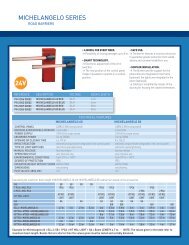
- Manopola di sblocco mod. MSC (fig.2)<br />
Manopola di sblocco fissa con chiave personalizzata.<br />
2) SICUREZZA<br />
L’automazione, se installata ed utilizzata correttamente, soddisfa il grado di sicurezza<br />
richiesto. Tuttavia è opportuno osservare alcune regole di comportamento<br />
per evitare inconvenienti accidentali.<br />
Prima di usare l’automazione, leggere attentamente le istruzioni d’uso e conservarle<br />
per consultazioni future.<br />
• Tenere bambini, persone e cose fuori dal raggio d’azione dell’automazione,<br />
in particolare durante il funzionamento.<br />
• Non lasciare radiocomandi o altri dispositivi di comando alla portata dei bambini<br />
onde evitare azionamenti involontari dell’automazione.<br />
• Non contrastare volontariamente il movimento dell’anta.<br />
• Non tentare di aprire manualmente il cancello se non è stato sbloccato l’attuatore<br />
con l’apposita manopola di sblocco.<br />
• Non modificare i componenti dell’automazione.<br />
• In caso di malfunzionamento, togliere l’alimentazione, attivare lo sblocco di<br />
emergenza per consentire l’accesso e richiedere l’intervento di un tecnico<br />
qualificato (installatore).<br />
• Per ogni operazione di pulizia esterna, togliere l’alimentazione di rete, e se<br />
presente almeno un polo delle batterie.<br />
• Tenere pulite le ottiche delle fotocellule ed i dispositivi di segnalazione luminosa.<br />
Controllare che rami ed arbusti non disturbino i dispositivi di sicurezza<br />
(fotocellule).<br />
• Per qualsiasi intervento diretto all’automazione, avvalersi di personale qualificato<br />
(installatore).<br />
• Annualmente far controllare l’automazione da personale qualificato.<br />
• L’entrata è riservata ai veicoli. Prevedere un’entrata separata per i<br />
pedoni.<br />
MANUALE D’USO<br />
• Per ripristinare il comando motorizzato, ruotare la manopola in senso<br />
antiorario per tutta la sua corsa, riportare la chiave in posizione di chiusura<br />
quindi togliere la chiave e riporla in un luogo sicuro e conosciuto<br />
agli interessati.<br />
4) MANUTENZIONE E DEMOLIZIONE<br />
La manutenzione dell’impianto va fatta eseguire regolarmente da parte<br />
di personale qualificato. I materiali costituenti l’apparecchiatura e il suo<br />
imballo vanno smaltiti secondo le norme vigenti.<br />
AVVERTENZE<br />
E’ richiesta l’installazione dei due cartelli forniti nella zona del cancello<br />
ed in una posizione nella quale risultino chiaramente visibili (Fig.12).<br />
Il buon funzionamento dell’operatore è garantito solo se vengono<br />
rispettate i dati riportati in questo manuale. La ditta non risponde dei<br />
danni causati dall’inosservanza delle norme di installazione e delle<br />
indicazioni riportate in questo manuale.<br />
Le descrizioni e le illustrazioni del presente manuale non sono impegnative.<br />
Lasciando inalterate le caratteristiche essenziali del prodotto, la Ditta si<br />
riserva di apportare in qualunque momento le modifiche che essa ritiene convenienti<br />
per migliorare tecnicamente, costruttivamente e commercialmente<br />
il prodotto, senza impegnarsi ad aggiornare la presente pubblicazione.<br />
CLOSE<br />
Fig. 1<br />
2<br />
Fig. 2<br />
OPEN<br />
1<br />
D811419_07<br />
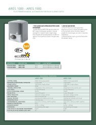
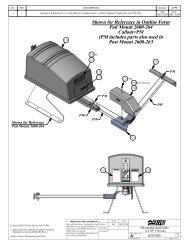
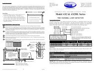
3) SBLOCCO MANUALE<br />
Lo sblocco manuale o di emergenza va attivato quando si deve aprire manualmente<br />
il cancello o in ogni caso di non funzionamento o funzionamento<br />
anomalo dell’automazione. Per eseguire la manovra di emergenza, bisogna:<br />
• Inserire la chiave standard nell’apposita sede (fig.1) e ruotarla in senso antiorario<br />
(90°), quindi ruotare la manopola di sblocco in senso orario per tutta la<br />
sua corsa. In questo modo si rende folle il pignone permettendo cosi, l’apertura<br />
manuale del cancello.<br />
Attenzione: Non spingere violentemente l’anta del cancello, ma<br />
accompagnarla per tutta la sua corsa.<br />
• Per ripristinare il comando motorizzato, ruotare la manopola in senso antiorario<br />
per tutta la sua corsa e quindi ruotare in senso orario la chiave standard fino<br />
alla ritenuta. Riporre la chiave in un luogo sicuro e conosciuto agli interessati<br />
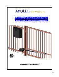
Nel caso sia applicata la manopola di sblocco con chiave personalizzata (fig.2),<br />
agire come segue:<br />
• Inserire la chiave personalizzata nella serratura, ruotare la chiave in senso<br />
antiorario per 90°.<br />
• Impugnare la manopola di sblocco e ruotarla in senso orario (fig.2) fino al suo<br />
arresto. In questo modo si rende folle il pignone permettendo cosi, l’apertura<br />
manuale del cancello.<br />
• Spingere manualmente l’anta del cancello accompagnandola per tutta la sua<br />
corsa.<br />
La chiave non si può togliere dalla serratura fino a quando la manopola non<br />
viene riportata nella posizione iniziale (azionamento motorizzato).<br />
CLOSE<br />
CLOSE<br />
2<br />
OPEN<br />
OPEN<br />
1<br />
MSC<br />
- <strong>DEIMOS</strong> <strong>BT</strong> <strong>UL</strong> Ver. 07
D811419_07<br />
Thank you for buying this product, our company is sure that you will be more<br />
than satisfied with the product’s performance. The product is supplied with<br />
a “Warnings” leaflet and an “Instruction booklet”. These should both be<br />
read carefully as they provide important information about safety, installation,<br />
operation and maintenance. This product complies with the recognised<br />
technical standards and safety regulations.<br />
1) GENERAL OUTLINE<br />
The <strong>DEIMOS</strong> <strong>BT</strong> <strong>UL</strong> actuator offers ample installation versatility thanks<br />
to its compactness, the extremely low position of its pinion as well as the<br />
height and depth adjustments available. The adjustable electronic torque<br />
limiter ensures antisquash safety. The emergency manual manoeuvre can be<br />
activated very easily by means of a knob. The end-of-run stop is controlled<br />
by electromechanical limit microswitches. The control unit is incorporated.<br />
Before each manoeuvre, the control unit performs a check of the operation<br />
relays and safety devices (photocells, rubber skirt, etc.).<br />
The incorporated control panel checks the drive relays and safety devices<br />
(photocells and safety edge) before carrying out any manoeuvre.<br />
The following optional accessories are available:<br />
- SBBAT mod. Buffer battery kit<br />
It can be incorporated into the actuator, and allows the automation system to<br />
operate even when the mains power supply is disconnected for a short time.<br />
- MSC mod. Release knob (fig.2)<br />
Fixed release knob with personalised key.<br />
USER’S MANUAL<br />
ENGLISH<br />
stroke, move the key back to its locking position; then take the key out<br />
and keep it in a safe place which is known to all the people concerned.<br />
4) MAINTENANCE AND DEMOLITION<br />
The maintenance of the system should only be carried out by qualified<br />
personnel regularly. The materials making up the set and its packing must<br />
be disposed of according to the regulations in force.<br />
WARNINGS<br />
The installation of the two supplied placards is required in the area of the<br />
gate and in a location where they are clearly visible. (Fig.12).<br />
Correct controller operation is only ensured when the data contained in<br />
the present manual are observed. The company is not to be held responsible<br />
for any damage resulting from failure to observe the installation<br />
standards and the instructions contained in the present manual.<br />
The descriptions and illustrations contained in the present manual are<br />
not binding. The Company reserves the right to make any alterations<br />
deemed appropriate for the technical, manufacturing and commercial<br />
improvement of the product, while leaving the essential product features<br />
unchanged, at any time and without undertaking to update the<br />
present publication.<br />
2) SAFETY<br />
If correctly installed and used, this automation device satisfies the required<br />
safety level standards. However, it is advisable to observe some practical<br />
rules in order to avoid accidental problems.<br />
Before using the automation device, carefully read the operation instructions<br />
and keep them for future reference.<br />
• Keep children, persons and things outside the automation working area,<br />
particularly during operation.<br />
• Keep radio control or other control devices out of children’s reach, in<br />
order to avoid any unintentional automation activation.<br />
• Do not intentionally oppose the leaf movement.<br />
• Do not attempt to open the gate by hand, if the actuator has not been<br />
released by means of the appropriate release knob.<br />
• Do not modify the automation components.<br />
• In case of malfunction, disconnect the power supply, activate the emergency<br />
release to gain access to the actuator and request the assistance<br />
of a qualified technician (installer).<br />
• Before proceeding to any external cleaning operation, disconnect the<br />
mains powers supply and at least one of the battery pole, if fitted.<br />
• Keep the photocell optical components and luminous signal indication<br />
devices clean. Check that the safety devices (photocells) are not obscured<br />
by branches or shrubs.<br />
• For any direct assistance to the automation system, request the assistance<br />
of a qualified technician (installer).<br />
• Have qualified personnel check the automation system once a year.<br />
• Entrance is reserved for vehicles, provide a separate entrance for<br />
pedestrians.<br />
3) MANUAL RELEASE<br />
The manual or emergency release is to be activated when a gate must<br />
be opened by hand, and in all cases where the automation system fails to<br />
operate or operates incorrectly. To carry out the emergency manoeuvre,<br />
proceed as follows:<br />
• Insert the standard key into its appropriate seat (fig. 1) and rotate it anticlockwise<br />
(90°), then rotate the release knob clockwise along its entire<br />
stroke. This way the pinion is made to idle, and therefore allows the gate<br />
to be opened by hand.<br />
Warning: Do not push the gate leaf hard, but rather help it along its<br />
entire stroke.<br />
• To reset motor-driven control, rotate the knob anticlockwise along its entire<br />
stroke, and then rotate the standard key clockwise until it is held tight. Keep<br />
the key in a safe place which is known to all the people concerned.<br />
In the case where the release knob is supplied with a personalised key<br />
(fig.2), proceed as follows:<br />
• Insert the personalised key into the lock, rotate the key anticlockwise by<br />
90°.<br />
• Hold the release knob and rotate it clockwise (fig. 2) until it stops. This<br />
way the pinion is made to idle, and therefore allows the gate to be opened<br />
by hand.<br />
• Push the gate leaf by hand, helping it along its entire stroke.<br />
The key cannot be taken out of the lock until the knob is brought back to<br />
its initial position (motor-driven activation).<br />
• To reset motor-driven control, rotate the knob anticlockwise along its entire<br />
CLOSE<br />
CLOSE<br />
CLOSE<br />
Fig. 1<br />
2<br />
Fig. 2<br />
2<br />
OPEN<br />
OPEN<br />
OPEN<br />
1<br />
1<br />
MSC<br />
<strong>DEIMOS</strong> <strong>BT</strong> <strong>UL</strong> Ver. 07 -
ITALIANO<br />
Nel ringraziarVi per la preferenza accordata a questo prodotto, la ditta è<br />
certa che da esso otterrete le prestazioni necessarie al Vostro uso. Leggete<br />
attentamente l’opuscolo “Avvertenze” ed il “Libretto istruzioni” che<br />
accompagnano questo prodotto in quanto forniscono importanti indicazioni<br />
riguardanti la sicurezza, l’installazione, l’uso e la manutenzione. Questo<br />
prodotto risponde alle norme riconosciute della tecnica e della disposizioni<br />
relative alla sicurezza.<br />
1) SICUREZZA GENERALE<br />
ATTENZIONE! Una installazione errata o un uso improprio del prodotto,<br />
può creare danni a persone, animali o cose.<br />
• Leggete attentamente l’opuscolo ”Avvertenze” ed il ”Libretto istruzio-ni”<br />
che accompagnano questo prodotto, in quanto forniscono Importanti indicazioni<br />
riguardanti la sicurezza, l’installazione, l’uso e la manutenzione.<br />
• Smaltire i materiali di imballo (plastica, cartone, polistirolo, ecc.) secon-do<br />
quanto previsto dalle norme vigenti. Non lasciare buste di nylon e<br />
polistirolo a portata dei bambini.<br />
• Questo prodotto è stato progettato e costruito esclusivamente per l’utilizzo<br />
indicato in questa documentazione.<br />
Usi non indicati in questa documentazione potrebbero essere fonte di<br />
danni al prodotto e fonte di pericolo.<br />
• La Ditta declina qualsiasi responsabilità derivante dall’uso improprio o<br />
diverso da quello per cui è destinato ed indicato nella presente documentazione.<br />
• Non installare il prodotto in atmosfera esplosiva.<br />
• La Ditta declina qualsiasi responsabilità dall’inosservanza della Buona<br />
Tecnica nella costruzione delle chiusure (porte, cancelli, ecc.), nonché<br />
dalle deformazioni che potrebbero verificarsi durante l’uso.<br />
• Togliere l’alimentazione elettrica, prima di qualsiasi intervento sull’impianto.<br />
Scollegare anche eventuali batterie tampone se presenti.<br />
• Prevedere sulla rete di alimentazione dell’automazione, un interruttoreo un<br />
magnetotermico onnipolare con distanza di apertura dei contatti uguale<br />
o superiore a 3,5 mm.<br />
• Verificare che a monte della rete di alimentazione, vi sia un interruttore<br />
differenziale con soglia da 0.03A.<br />
• Verificare se l’impianto di terra è realizzato correttamente: collegare tutte<br />
le parti metalliche della chiusura (porte, cancelli, ecc.) e tutti i componenti<br />
dell’impianto provvisti di morsetto di terra.<br />
• Applicare tutti i dispositivi di sicurezza (fotocellule, coste sensibili, ecc.)<br />
necessari a proteggere l’area da pericoli di schiacciamento, convogliamento,<br />
cesoiamento.<br />
• Applicare almeno un dispositivo di segnalazione luminosa (lampeggiante)<br />
in posizione visibile, fissare alla struttura un cartello di Attenzione.<br />
• La Ditta declina ogni responsabilità ai fini della sicurezza e del buon<br />
funzionamento dell’automazione se vengono impiegati componenti di<br />
altri produttori.<br />
• Usare esclusivamente parti originali per qualsiasi manutenzione o riparazione.<br />
• Non eseguire alcuna modifica ai componenti dell’automazione se non<br />
espressamente autorizzata dalla Ditta.<br />
• Istruire l’utilizzatore dell’impianto per quanto riguarda i sistemi di coman-do<br />
applicati e l’esecuzione dell’apertura manuale in caso di emergenza.<br />
• Non permettere a persone e bambini di sostare nell’area d’azione dell’automazione.<br />
• Non lasciare radiocomandi o altri dispositivi di comando alla portata dei<br />
bambini onde evitare azionamenti involontari dell’automazione.<br />
• L’utilizzatore deve evitare qualsiasi tentativo di intervento o riparazione<br />
dell’automazione e rivolgersi solo a personale qualificato.<br />
• Tutto quello che non è espressamente previsto in queste istruzioni, non<br />
è permesso.<br />
• L’installazione deve essere fatta utilizzando dispositivi di sicurezza e<br />
comandi conformi alla EN 12978<br />
2) GENERALITÀ<br />
L’attuatore <strong>DEIMOS</strong> <strong>BT</strong> <strong>UL</strong> offre un’ampia versatilità d’installazione, grazie<br />
alla posizione estremamente bassa del pignone, alla compattezza dell’attuatore<br />
e alla regolazione dell’altezza e profondità di cui dispone.Il limitatore<br />
di coppia elettronico, regolabile, garantisce la sicurezza contro lo schiacciamento.<br />
La manovra manuale d’emergenza si effettua con estrema facilità<br />
tramite una manopola. L’arresto a fine corsa è controllato da microinterruttori<br />
elettromeccanici.<br />
Il quadro comando incorporato effettua il controllo dei relè di marcia e dei dispositivi<br />
di sicurezza (fotocellule, costa sensibile), prima di eseguire ogni manovra.<br />
Il motoriduttore (fig.1) è costituito da:<br />
M Motore.<br />
R Riduttore a vite senza fine - ruota elicoidale.<br />
F<br />
Gruppo finecorsa elettromeccanico.<br />
P Pignone.<br />
S Meccanismo di sblocco.<br />
QSC-D <strong>UL</strong> Quadro comando.<br />
Sono disponibili i seguenti accessori opzionali:<br />
- Kit batteria tampone mod. SBBAT<br />
Incorporabile nell’attuatore, consente il funzionamento dell’automazione<br />
anche se manca per un breve periodo l’alimentazione di rete.<br />
- <strong>DEIMOS</strong> <strong>BT</strong> <strong>UL</strong> Ver. 07<br />
MANUALE PER L’INSTALLAZIONE<br />
La confezione é composta da (fig.1):<br />
• 2 batterie a tampone (rif.B).<br />
• 1 base porta batterie (rif.BB).<br />
• 1 scheda carica batterie (rif.SBS).<br />
• Manuale istruzioni per il montaggio.<br />
• Confezione viteria e cablaggi vari.<br />
- Manopola di sblocco mod. MSC (fig.18)<br />
Manopola di sblocco fissa con chiave personalizzata.<br />
INSTALLARE L’APRICANCELLO SOLO QUANDO:<br />
• L’attuatore risulta idoneo per la tipologia costruttiva del cancello e per<br />
la classe di utilizzo del cancello.<br />
• Tutti i punti di schiacciamento evidenti sono protetti o schermati.<br />
• L’apricancello è concepito per essere installato solo su cancelli utilizzati per il<br />
passaggio di veicoli. Per i pedoni devono essere previsti accessi separati.<br />
• Il cancello deve essere installato in una posizione tale da garantire una<br />
distanza sufficiente tra il cancello e le strutture adiacenti durante l’apertura<br />
e la chiusura, al fine di ridurre il rischio di intrappolamento.<br />
I cancelli a battente non potranno essere aperti in aree di pubblico accesso.<br />
• Il cancello deve essere installato correttamente e deve funzionare liberamente<br />
in entrambe le direzioni prima dell’installazione dell’apricancello.<br />
Non serrare eccessivamente la frizione dell’attuatore o la valvola di sfiato<br />
della pressione per rimediare ad un cancello danneggiato.<br />
IN CASO DI APRICANCELLI CON COMANDO UOMO PRESENTE:<br />
• I comandi dell’apricancello devono essere posizionati in modo tale che<br />
l’utilizzatore abbia una visuale completa dell’area del cancello quando il<br />
cancello è in movimento.<br />
• Dovrà essere posizionato vicino ai comandi un cartello recante la scritta<br />
“AVVERTENZA” dalle lettere alte almeno 6,4 mm. e la seguente dichiarazione:<br />
“ Il cancello in movimento è in grado di causare lesioni o morte<br />
- non azionate il cancello quando il percorso non è libero”.<br />
• Non dovranno essere utilizzati dispositivi di chiusura automatici (quali<br />
temporizzatori, rilevatori di spira o dispositivi similari).<br />
• Non dovrà essere collegato nessun altro dispositivo di attivazione.<br />
I comandi devono essere sufficientemente lontani dal cancello in modo<br />
che l’utente non possa venire a contatto con il cancello quando utilizza tali<br />
comandi. I comandi previsti per il resettaggio dell’attuatore dopo due attivazioni<br />
successive del dispositivo/i contro l’intrappolamento devono essere<br />
posizionati sulla linea visiva del cancello. I comandi esterni o facilmente<br />
accessibili dovranno essere dotati di protezione al fine di impedirne l’utilizzo<br />
non autorizzato.<br />
I segnali di avvertenza e i cartelli devono essere installati in una posizione<br />
visibile nell’area del cancello.<br />
IN CASO DI ATTUATORI CHE UTILIZZANO UN SENSORE CON RILEVA-<br />
MENTO SENZA CONTATTO:<br />
• Leggere le istruzioni sul posizionamento dei sensori senza contatto per<br />
ogni tipo di applicazione.<br />
• Provvedere affinché venga ridotto al minimo il rischio di intervento di<br />
disturbi come quando, ad esempio, il veicolo fa scattare il sensore mentre<br />
il cancello è ancora in movimento.<br />
• Posizionare uno o più sensori senza contatto dove esiste il rischio di<br />
intrappolamento o ostruzione, ad esempio lungo il perimetro raggiunto<br />
dal cancello in movimento o da una barriera.<br />
IN CASO DI ATTUATORI CHE UTILIZZANO UN SENSORE CON RILEVA-<br />
MENTO A CONTATTO (COSTA SENSIBILE O EQUIVALENTE):<br />
• Dovranno essere installati uno o più sensori di contatto sul punto di<br />
serraggio di cancelli verticali a cardine per passaggio veicolare.<br />
• Dovrà essere installato un sensore con contatto a circuito permanente i<br />
cui cablaggi dovranno essere disposti in modo tale che la comunicazione<br />
tra il sensore e l’apricancello non sia soggetta a danni meccanici.<br />
• Dovrà essere installato un sensore con contatto senza fili quale ad esempio<br />
un sensore che trasmette segnali di frequenze radio (RF) all’apricancello<br />
per le funzioni di protezione contro l’intrappolamento nei casi in cui la<br />
trasmissione dei segnali non sia ostacolata o impedita dalla struttura<br />
dell’edificio, dal paesaggio naturale o da ostacoli similari. Il sensore con<br />
contatto senza fili dovrà funzionare conformemente alle condizioni per<br />
l’utilizzo finale previste.<br />
IMPORTANTI PRESCRIZIONI DI SICUREZZA ATTENZIONE: al fine<br />
di ridurre il rischio di danni fisici o morte:<br />
• Leggere e osservare tutte le istruzioni.<br />
• Non permettere ai bambini di utilizzare o giocare con i comandi del cancello.<br />
Tenere il telecomando fuori dalla portata dei bambini.<br />
• Tenere lontani oggetti e persone dal cancello. NON E’ PERMESSO<br />
ATTRAVERSARE IL PERCORSO ESEGUITO DAL CANCELLO IN<br />
MOVIMENTO.<br />
D811419_07
D811419_07<br />
• Tutte le aperture di un cancello a scorrimento orizzontale sono riparate o<br />
schermate dal basso fino ad un minimo di 4 piedi (1,2 m) da terra, onde<br />
prevenire che un oggetto sferico dal diametro di 2-1/4 pollici (57,15 mm) passi<br />
attraverso le aperture in qualsiasi punto del cancello e in quella porzione della<br />
recinzione adiacente coperta dal cancello stesso in posizione di apertura;<br />
• Tutti i punti di pinzatura esposti risultano eliminati o riparati ed esistono<br />
dei ripari per i rulli esposti.<br />
• Sottoporre a prova l’azionamento per cancelli una volta al mese. Il cancello<br />
DEVE eseguire la corsa inversa (marcia indietro) quando entra in contatto<br />
con un oggetto rigido oppure arrestarsi quando un oggetto attiva i sensori<br />
anticontatto. Se l’azionamento del cancello non funziona correttamente,<br />
avvalersi di un tecnico specializzato nella manutenzione per far regolare<br />
la coppia del motore o il limite della corsa e quindi eseguire una nuova<br />
prova dell’azionamento.<br />
In caso di mancata prova di riscontro o qualora le regolazioni dell’azionamento<br />
necessarie al suo corretto funzionamento non fossero eseguite<br />
risulterà maggiore il rischio di lesioni o di morte.<br />
• Utilizzare lo sblocco di emergenza solamente quando il cancello non è in<br />
movimento.<br />
• ESEGUIRE UN’ADEGUATA MANUTENZIONE DEI CANCELLI. Leggere<br />
il manuale per l’utilizzatore. Avvalersi di personale specializzato nella<br />
manutenzione per eseguire eventuali riparazioni sui componenti meccanici<br />
in metallo del cancello.<br />
• L’entrata è riservata ai veicoli. I pedoni devono utilizzare un accesso<br />
separato.<br />
• CONSERVARE LE PRESENTI ISTRUZIONI.<br />
3) DATI TECNICI<br />
3.1) Attuatore <strong>DEIMOS</strong> <strong>BT</strong> <strong>UL</strong><br />
Alimentazione: ............................................monofase 120V ±10% 60Hz (*)<br />
Motore:.............................................................................................. 24V<br />
Giri motore:.................................................................................. 3500min -1<br />
Potenza assorbita:................................................................................ 70W<br />
Corrente assorbita max:................................... 0,5A (120V~) - 1A (110V~)<br />
Rapporto di riduzione: .......................................................................... 1/44<br />
Giri in uscita: ....................................................................................79min -1<br />
Modulo pignone:.......................................................0,157”( 4mm (14 denti)<br />
Velocità anta:...................................................................... 7,87”/s (0,2 m/s)<br />
Peso anta max: .................................................1102,3 lb (5000N (≈500kg)<br />
Coppia max: ..................................................................14,747 lb ft (20Nm)<br />
Reazione all’urto: ........................................Limitatore di coppia elettronico<br />
Lubrificazione: ..............................................................Grasso permanente<br />
Manovra manuale:..................................... Sblocco meccanico a manopola<br />
N° manovre in 24 ore:.............................................................................. 30<br />
Centralina di controllo: ............................................................... incorporata<br />
Batterie tampone (opzionali): ..................................2 batterie da12V 1,2Ah<br />
Condizioni ambientali: ..................................................... da -15°C a +40°C<br />
Grado di protezione: ............................................................................. IP24<br />
Rumorosità:.....................................................................................
ITALIANO<br />
2 metri - portata oltre i 4409,2 lb (2000kg (≈ 20000N)). Questi pezzi devono<br />
essere, prima saldati ad un adeguato angolare di ferro e poi il tutto, saldato<br />
al cancello. L’angolare, oltre a mantenere la distanza fra la cremagliera ed<br />
il fianco del cancello, agevola la fase di fissaggio al cancello stesso, anche<br />
se questo ha dei leggeri sbandamenti laterali. Nelle saldature di giunzione<br />
dei vari pezzi di cremagliera, si consiglia di disporre uno spezzone di cremagliera<br />
come in (fig.7) per garantire il passo corretto per tutta la lunghezza<br />
della cremagliera.<br />
7.2) Mod. CPZ (Fig.8).<br />
Cremagliera di plastica - sez. 0,866”x0,866”(22x22mm) - fornita in pezzi<br />
da 3,28 ft (1m) - portata max. 1102,3 lb(500kg (≈ 5000N)). Questo modello<br />
va fissato al cancello con viti normali o autofilettanti. È opportuno anche<br />
in questo caso, interporre uno spezzone al contrario nella giunzione tra i<br />
vari spezzi in modo da mantenere il passo corretto dei denti. Questo tipo di<br />
cremagliera, è più silenziosa e permette regolazioni in altezza anche dopo<br />
il fissaggio, per mezzo di feritoie previste.<br />
7.3) Mod. CVZ (Fig.8)<br />
Cremagliera di ferro zincato sez. 1,18x0,47 (30x12mm) fornita in pezzi da<br />
3,28 ft (1m) - distanziali filettati a saldare - portata max. 4409,2 lb (2000kg<br />
(≈ 20000N)). Fissati i distanziali in centro ad ogni asola dei vari pezzi di cremagliera,<br />
saldare i distanziali al cancello. Anche in questo caso, sistemare<br />
uno spezzone al contrario nei punti di giunzione dei vari pezzi di cremagliera<br />
per garantire il passo corretto dei denti. Le viti che fissano la cremagliera ai<br />
distanziali, consentono regolazioni in altezza della cremagliera.<br />
7.4) Fissaggio della cremagliera<br />
Per il montaggio della cremagliera, eseguire quanto segue:<br />
• Attivare lo sblocco di emergenza ruotando l’apposita manopola di sblocco<br />
(Vedere paragrafo “Manovra di emergenza”).<br />
• Appoggiare l’estremità della cremagliera sul pignone di comando ed eseguire<br />
il fissaggio (con saldatura o con viti) in corrispondenza del pignone<br />
facendo scorrere manualmente il cancello (fig.9).<br />
• Nel caso di cancello irregolare (eccessiva curvatura laterale), se non è<br />
possibile correggerla, bisogna interporre degli spessori fra cremagliera<br />
e cancello in modo da garantire sempre il centraggio della cremagliera<br />
rispetto al pignone (fig.10).<br />
PERICOLO - L’operazione di saldatura va eseguita da persona capace e<br />
dotata di tutti i dispositivi di protezione individuali previsti dalle norme<br />
di sicurezza vigenti.<br />
8) REGOLAZIONE PIGNONE<br />
Terminato il fissaggio della cremagliera è necessario regolare il gioco<br />
cremagliera - pignone che deve essere di circa 0,078” (2mm) (fig.6): ciò si<br />
ottiene allentando per circa 0,078”(2mm), i quattro dadi M10 sotto la base del<br />
motoriduttore e fissando poi i quattro dadi superiori. Assicurare l’allineamento<br />
ed il centraggio della cremagliera - pignone (fig.10).<br />
ATTENZIONE - Ricordarsi che la durata della cremagliera e del pignone<br />
dipendono in modo determinante dal corretto ingranamento.<br />
9) FINECORSA ELETTROMECCANICI<br />
L’operazione va eseguita con sblocco di emergenza attivato e senza alimentazione<br />
di rete. I pattini che comandano i finecorsa vanno posizionati alle<br />
estremità della cremagliera.<br />
- Spingere manualmente il cancello in completa apertura.<br />
- Posizionare il pattino finecorsa di apertura (fig.11) in modo che intercetti<br />
la leva di comando del micro e che lo facciano scattare. Individuata la<br />
posizione corretta, serrare le viti del pattino.<br />
- Spingere manualmente il cancello in completa chiusura.<br />
- Posizionare il pattino finecorsa di chiusura (fig.11) in modo che intercetti<br />
la leva di comando del micro e che lo facciano scattare.<br />
Individuata la posizione corretta, serrare le viti del pattino.<br />
- I pattini, devono bloccare il cancello, prima che questo intercetti i fermi d’arresto<br />
meccanici posti sulla rotaia. La regolazione del pattino finecorsa di chiusura<br />
deve essere fatta in modo da lasciare un franco di circa 50mm fra il cancello<br />
ed il battente fisso, come previsto dalle norme di sicurezza vigenti oppure,<br />
applicare una costa sensibile di almeno 50mm di spessore (fig.12).<br />
10) FERMI D’ARRESTO<br />
PERICOLO - Il cancello deve essere dotato dei fermi d’arresto meccanici<br />
sia in apertura sia in chiusura, in modo da impedire la fuoriuscita<br />
del cancello dalla guida superiore (fig.13); devono essere solidamente<br />
fissati a terra, qualche centimetro oltre il punto d’arresto elettrico.<br />
11) PREDISPOSIZIONE IMPIANTO ELETTRICO<br />
Predisporre l’impianto elettrico come indicato in fig.14 facendo riferimento<br />
alle norme vigenti per gli impianti elettrici CEI 64-8, IEC364, armonizzazione<br />
HD384 ed altre norme nazionali.<br />
ATTENZIONE! Per il collegamento alla rete, utilizzare cavo multipolare<br />
di sezione minima 3x16AWG e del tipo previsto dalle normative vigenti.<br />
A titolo di esempio, se il cavo è all’esterno (all’aperto), deve essere<br />
almeno pari a H07RN-F mentre, se all’interno (in canaletta), deve essere<br />
almeno pari a H05 VV-F con sezione 3x16AWG.<br />
- <strong>DEIMOS</strong> <strong>BT</strong> <strong>UL</strong> Ver. 07<br />
MANUALE PER L’INSTALLAZIONE<br />
Realizzare i collegamenti dei dispositivi di comando e di sicurezza in armonia<br />
con le norme per la tecnica degli impianti precedentemente citate. I cavi<br />
(rete e ausiliari) devono essere nettamente separati. In fig.14 è riportato il<br />
numero di collegamenti e la loro sezione per una lunghezza di circa 328,08<br />
ft (100 metri); per lunghezze superiori, calcolare la sezione per il carico<br />
reale dell’automazione.<br />
I componenti principali per una automazione sono (fig.14):<br />
I Interruttore onnipolare omologato di adeguata portata con apertura<br />
contati di almeno 0,14”(3,5 mm) provvisto di protezione contro i<br />
sovraccarichi ed i corti circuiti, atto a sezionare l’automazione<br />
dalla rete. Se non presente, prevedere a monte dell’automazione<br />
un interruttore differenziale omologato con soglia 0,03A.<br />
QR Quadro comando e ricevente incorporata<br />
S Selettore a chiave<br />
AL Lampeggiante con antenna accordata<br />
M Attuatore<br />
P Pulsantiera a muro<br />
Fte, Fre Coppia fotocellule esterne<br />
T Trasmittente 1-2-4 canali<br />
C Cremagliera<br />
INSTALLAZIONE ANTENNA<br />
Usare una antenna accordata sui 433MHz.<br />
Per il collegamento Antenna-Ricevitore usare cavo coassiale RG58.<br />
La presenza di masse metalliche a ridosso dell’antenna, può disturbare la<br />
ricezione radio. In caso di scarsa portata del trasmettitore, spostare l’antenna<br />
in un punto più idoneo.<br />
12) COLLEGAMENTI MORSETTIERA<br />
Passati gli adeguati cavi elettrici nelle canalette e fissati i vari componenti<br />
dell’automazione nei punti prescelti, si passa al loro collegamento secondo<br />
le indicazioni e gli schemi riportati nei relativi manuali istruzione. Effettuare<br />
la connessione della fase, del neutro e della terra (obbligatoria). Il cavo di<br />
rete va bloccato nell’apposito pressacavo (fig.15-rif.P1), i cavi degli accessori<br />
nel pressacavo (fig.15-rif.P2), il conduttore di protezione (terra) con guaina<br />
isolante di colore giallo/verde, deve essere collegato nell’apposito serrafilo<br />
(fig.15-rif.S). L’automazione va messa in funzione quando sono collegati e<br />
verificati tutti i dispositivi di sicurezza. Vedi schema morsettiera fig.16.<br />
JP2<br />
1-2 Collegamento motore (1 Blu - 2 Rosso).<br />
3-4 Secondario trasformatore 24V.<br />
ATTENZIONE - Se il verso di apertura non è corretto, invertire i collegamenti<br />
1 e 2 del motore ed i collegamenti 6 e 7 dei finecorsa di<br />
apertura e chiusura.<br />
JP3<br />
5-6 Fine corsa chiusura SWC (5 Nero comune - 6 Rosso).<br />
5-7 Fine corsa apertura SWO (5 Nero comune - 7 Marrone).<br />
8-9 Lampeggiante 24V max 25W.<br />
10-11 Antenna (10 segnale - 11 calza).<br />
12-13 Alimentazione accessori:<br />
24 V~ funzionamento in presenza di rete.<br />
24 V (12+,13-) funzionamento in assenza di rete e kit opzionale<br />
batteria tampone. Mod. SB BAT.<br />
14-15 Uscita 24 Vac per segnale acustico (Fig.19A).<br />
16-17 Uscita alimentazione dispositivi di sicurezza (trasmettitore fotocellule<br />
e trasmettitore costa sensibile).<br />
N.B.: uscita attiva solo durante il ciclo di manovra.<br />
24 V~ funzionamento in presenza di rete.<br />
24 V (16-,17+) funzionamento in assenza di rete e kit opzionale<br />
batteria tampone. Mod. SB BAT.<br />
18 Ingresso dispositivi di sicurezza FA<strong>UL</strong>T (vedere punto 13).<br />
19-20 Pulsante comando pedonale PED (N.O.) Apre il cancello per un tempo<br />
di 5 secondi con le modalità della logica impostata (3 o 4 passi).<br />
21-22 Pulsante di comando START/CLOSE e selettore a chiave (N.O.).<br />
21-23 Pulsante di comando STOP (N.C.).In ogni caso, arresta l’automazione<br />
fino a nuovo start. Se non si usa, lasciare ponticellato.<br />
24 Ingresso PHOT, fotocellula e costa sensibile (vedere punto 13).<br />
21-25 Ingresso contatto costa sensibile BAR (N.C.). In caso di intervento<br />
si ha l’arresto e l’inversione per circa 3s. Se non si usa, lasciare<br />
ponticellato.<br />
21-26 Pulsante di comando APRE (Open) (N.O.).<br />
JP1<br />
31-32 Primario trasformatore 120V~.<br />
33-34 Alimentazione monofase 120V~, 60 Hz (33N - 34L).<br />
13) COLLEGAMENTO DISPOSITIVI DI SICUREZZA<br />
Nota: utilizzare solamente dispositivi di sicurezza riceventi con contatto<br />
in libero scambio (rif. particolare figura 19).<br />
Per il collagamento dei dispositivi di sicurezza verificati, fare riferimento allo<br />
schema riportato in Fig.19, considerando il numero di coppie impiegate: 1<br />
coppia riquadro 1C, 2 coppie riquadro 2C, 3 coppie riquadro 3C e 4 coppie<br />
riquadro 4C. La centralina esegue il test di 3 o 4 dispositivi di sicurezza solo<br />
con la scheda aggiuntiva SCS1-MA (vedi Fig.21). I dispositivi aggiuntivi devono<br />
essere con autodiagnosi interna e collegati in serie tra loro. Nel caso<br />
D811419_07
D811419_07<br />
non vengano utilizzate, lasciare i ponticelli a filo tra i morsetti 21/23, 21/24<br />
e tra i morsetti 21/25 della scheda QSC D <strong>UL</strong>.<br />
14) PROGRAMMAZIONE<br />
Il quadro comandi dotato di microprocessore, viene fornito con parametri di<br />
funzionamento preimpostati dal costruttore, validi per installazioni standard.<br />
I parametri predefiniti possono essere variati mediante il programmatore a<br />
display incorporato o mediante programmatore palmare universale.<br />
Nel caso la programmazione venga effettuata mediante programmatore<br />
palmare universale, leggere attentamente le istruzioni relative al programmatore<br />
palmare universale e procedere come segue.<br />
Collegare il programmatore palmare universale alla centrale tramite l’accessorio<br />
UNIFLAT e UNIDA (Vedere fig.17). La centrale QSC-D <strong>UL</strong> non<br />
alimenta il programmatore palmare universale che quindi necessita di<br />
apposito alimentatore.<br />
Entrare nel menù “CENTRALINE”, nel sottomenù “PARAMETRI” e scorrere<br />
le schermate del display con le frecce su/giù impostando numericamente i<br />
valori dei parametri di seguito elencati.<br />
Per le logiche di funzionamento, riferirsi al sottomenù “LOGICA”.<br />
Nel caso si proceda alla programmazione mediante il programmatore incorporato<br />
fare riferimento alla Fig. A e B e al paragrafo “configurazione”.<br />
N.B.: La centralina QSC-D <strong>UL</strong> non può alimentare il programmatore<br />
palmare universale.<br />
15) Configurazione<br />
Il programmatore a display consente di impostare tutte le funzioni del quadro<br />
comandi QSC-D <strong>UL</strong>.<br />
Il programmatore dispone di tre pulsanti per la navigazione tra i menu e la<br />
configurazione dei parametri di funzionamento:<br />
+ tasto scorrimento menu/incremento valore<br />
- tasto scorrimento menu/riduzione valore<br />
OK tasto di invio (conferma)<br />
La pressione simultanea dei tasti + e - consente di uscire menu in cui si sta<br />
operando e passare al menu superiore.<br />
Le modifiche apportate vengono impostate solo se seguite dalla pressione<br />
del tasto OK.<br />
Con la prima pressione del tasto OK si entra in modalità programmazione.<br />
Inizialmente sul display compaiono le seguenti informazioni:<br />
- Versione Software centrale di comando<br />
- Numero manovre totali effettuate (il valore è espresso in centinaia quindi<br />
durante le prime cento manovre il display indica costantemente 0000)<br />
- Numero manovre effettuate dall’ultima manutenzione (il valore è espresso<br />
in centinaia quindi durante le prime cento manovre il display indica<br />
costantemente 0000)<br />
- Numero radiocomandi memorizzati.<br />
Una pressione del tasto OK durante la fase di presentazione iniziale consente<br />
di passare direttamente al primo menu.<br />
Di seguito vengono elencati i menu principali ed i relativi sottomenu disponibili.<br />
Il parametro predefinito, è quello chiuso fra parentesi quadre [ 0 ]. Tra<br />
parentesi rotonde viene indicata la scritta che appare sul display.<br />
Fate riferimento alle Tabelle A e B per la procedura di configurazione.<br />
15.1) Menu parametri (PARAM)<br />
- Tempo Chiusura Automatica (TCA) [10s]<br />
Impostare numericamente il valore del tempo di apertura automatica da<br />
3 a 120 secondi.<br />
- Coppia motori apertura (C. ap) [ 80% ]<br />
Impostare numericamente il valore di coppia dei motori tra 1% e 99%.<br />
- Coppia motori chiusura (C. ch) [ 80% ]<br />
Impostare numericamente il valore di coppia dei motori tra 1% e 99%.<br />
- Coppia motori apertura in rallentamento (C. ap. rALL) [ 50% ]<br />
(Parametri avanzati ⇒ indirizzo 8)<br />
Impostare numericamente il valore di coppia dei motori tra 1% e 99%.<br />
- Coppia motori chiusura in rallentamento (C. ch. rALL) [ 50% ]<br />
(Parametri avanzati ⇒ indirizzo 9)<br />
Impostare numericamente il valore di coppia dei motori tra 1% e 99%.<br />
- Tempo Veloce in Apertura (T vel ap,) [ 15 s. ]<br />
(Parametri avanzati ⇒ indirizzo 6)<br />
Impostare il tempo a velocità di apertura normale (non rallentata), variabile<br />
da 1 secondo a 2 min.<br />
- Tempo Veloce in Chiusura (T vel ch,) [ 15 s. ]<br />
(Parametri avanzati ⇒ indirizzo 7)<br />
Impostare il tempo a velocità di chiusura normale (non rallentata), variabile<br />
da 1 secondo a 2 min.<br />
Nota: Il tempo di rallentamento, in chiusura e in apertura, si ottiene cronometrando<br />
la durata di una manovra, ed impostando un valore minore<br />
in questo parametro. Se ad esempio la durata di una manovra è di 15<br />
secondi, impostando un “tempo velocità normale” di 12s si otterranno 3s<br />
di rallentamento.<br />
- Velocità rallentamento (vel rall,) [ 0 ]<br />
(Parametri avanzati ⇒ indirizzo 5)<br />
MANUALE PER L’INSTALLAZIONE<br />
Impostare la velocità di rallentamento scegliendo uno di questi valori:<br />
0 - rallentamento disabilitato<br />
1 - rallentamento al 50% della velocità normale<br />
2 - rallentamento al 33% della velocità normale<br />
3 - rallentamento al 25% della velocità normale<br />
- Zona (Zone) [ 0 ]<br />
(Parametri avanzati ⇒ indirizzo 1)<br />
Impostare il numero di zona tra un valore minimo di 0 ed un valore massimo<br />
di 127. Vedi paragrafo “Connessione seriale”.<br />
15.2) MENU Logiche (LOGIC)<br />
- TCA (TCA) [ OFF ]<br />
ON Attiva la chiusura automatica<br />
OFF Esclude la chiusura automatica.<br />
- 3 Passi (3 Passi) [ OFF ]<br />
ON Abilita la logica 3 passi. Un impulso di start ha i seguenti effetti:<br />
porta chiusa:............................................................................... apre<br />
in apertura:....................... ferma ed inserisce il TCA (se configurato)<br />
porta aperta: ...........................................................................chiude<br />
in chiusura:................................................................... ferma e riapre<br />
OFF Abilita logica 4 passi. Un impulso di start ha i seguenti effetti:<br />
porta chiusa:............................................................................... apre<br />
in apertura:....................... ferma ed inserisce il TCA (se configurato)<br />
porta aperta: ...........................................................................chiude<br />
in chiusura:.................................... ferma e non inserisce il tca (stop)<br />
dopo stop:................................................................................... apre<br />
- Blocca Impulsi (BlImp) [ OFF ]<br />
ON L’impulso di start non ha alcun effetto durante la fase di apertura.<br />
OFF L’impulso di start ha effetto durante la fase di apertura o chiusura.<br />
- Fotocellule in apertura (Fotoc ap) [ OFF ]<br />
ON: in caso di oscuramento, esclude il funzionamento della fotocellula in<br />
apertura. In fase di chiusura, inverte immediatamente.<br />
OFF: in caso di oscuramento, le fotocellule sono attive sia in apertura che<br />
in chiusura. Un oscuramento della fotocellula in chiusura, inverte il<br />
moto solo dopo il disimpegno della fotocellula.<br />
- Test fotocellule (test phot) [ OFF ]<br />
(Logiche avanzate ⇒ indirizzo 14)<br />
ON Attiva la verifica delle fotocellule<br />
OFF Disattiva la verifica delle fotocellule<br />
Se disabilitato (OFF) inibisce la funzione di verifica delle fotocellule,<br />
consentendo la connnessione di dispositivi non dotati di contatto<br />
supplementare verifica.<br />
- Preallarme (preall) [ OFF ]<br />
ON<br />
Il lampeggiante si accende circa 3 secondi prima della partenza dei<br />
motori.<br />
OFF Il lampeggiante si accende contemporanteamente alla partenza dei<br />
motori.<br />
- Uomo presente (uomo pres) [ OFF ]<br />
ON Funzionamento a uomo presente: la manovra continua finché viene<br />
mantenuta la pressione sul tasto di comando. (OPEN-CLOSE).<br />
OFF Funzionamento a impulsi, secondo la logica 3 o 4 passi.<br />
- Selezione START - CLOSE (start - close) [ OFF ]<br />
ON L’ingresso tra i due morsetti 21-22 funziona come CLOSE.<br />
OFF L’ingresso tra i due morsetti 21-22 funziona come START.<br />
- Codice Fisso (codice fisso) [ OFF ]<br />
(Logiche avanzate ⇒ indirizzo 13)<br />
ON<br />
Il ricevitore risulta configurato per il funzionamento in modalità codice<br />
fisso.<br />
OFF Il ricevitore risulta configurato per il funzionamento in modalità rollingcode.<br />
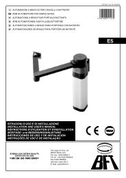
- Programmazione radiocomandi (prog radio) [ ON ]<br />
(Logiche avanzate ⇒ indirizzo 15)<br />
ON<br />
Abilita la memorizzazione via radio dei trasmettitori:<br />
1- Premere in sequenza il tasto nascosto (P1) e il tasto normale (T1-<br />
T2-T3-T4) di un trasmettitore già memorizzato in modalità standard<br />
attraverso il menu radio.<br />
2- Premere entro 10s il tasto nascosto (P1) ed il tasto normale (T1-<br />
T2-T3-T4) di un trasmettitore da memorizzare.<br />
La ricevente esce dalla modalità programmazione dopo 10s, entro<br />
questo tempo è possibile inserire ulteriori nuovi trasmettitori.<br />
Questa modalità non richiede l’accesso al quadro comando.<br />
OFF Disabilita la memorizzazione via radio dei trasmettitori.<br />
I trasmettitori vengono memorizzati solo utilizzando l’apposito menu<br />
Radio.<br />
- Loop (LOOP) [ OFF ]<br />
(Logiche avanzate ⇒ indirizzo 11)<br />
ON<br />
ITALIANO<br />
Nel caso di collegamento centralizzato chiuso ad anello (Fig.20),<br />
settare la centrale su ON.<br />
OFF Nel caso di collegamento centralizzato aperto (Fig.20) settare la<br />
centrale su OFF.<br />
- Master/Slave (master) [ OFF ]<br />
(Logiche avanzate ⇒ indirizzo 12)<br />
<strong>DEIMOS</strong> <strong>BT</strong> <strong>UL</strong> Ver. 07 -
ITALIANO<br />
ON Il quadro comando viene settato come Master in un collegamento<br />
centralizzato (vedi Paragrafo 16).<br />
OFF Il quadro comando viene settato come Slave in un collegamento<br />
centralizzato (vedi Paragrafo7).<br />
15.3) MENU RADIO (RADIO)<br />
Nel caso di installazioni standard nelle quali non siano richieste le funzionalità<br />
avanzate è possibile procedere alla memorizzazione manuale dei trasmettitori,<br />
facendo riferimento alla Fig.B per la programmazione base:<br />
- Aggiungi<br />
Consente di aggiungere un tasto di un radiocomando nella memoria della<br />
ricevente, dopo la memorizzazione restituisce il numero della ricevente<br />
nella locazione della memoria (da 01 a 64).<br />
Aggiungi Tasto Start (Agg start)<br />
associa il tasto desiderato al comando start<br />
Nota: Il tasto nascosto P1 assume aspetto diverso a seconda del modello<br />
di trasmettitore.<br />
Per i trasmettitori dotati di tasto nascosto, premere il pulsante nascosto<br />
P1 (Fig.B1). Per i trasmettitori sprovvisti del tasto nascosto, il tasto P1<br />
corrisponde alla pressione contemporanea dei 4 tasti del trasmettitore o,<br />
aprendo il vano batteria, a ponticellare con un cacciavite le due piazzole<br />
P1 (Fig.B2).<br />
- Leggi (Leggi)<br />
Effettua una verifica di un tasto di una ricevente, se memorizzato restituisce<br />
numero della ricevente nella locazione della memoria (da 01 a<br />
64) e numero del tasto (T1-T2-T3 o T4).<br />
- Elimina Lista (elim. 64)<br />
ATTENZIONE! Rimuove completamente dalla memoria della ricevente<br />
tutti i radiocomandi memorizzati.<br />
- Lettura codice ricevitore (cod RX)<br />
Visualizza il codice inserito nel ricevitore.<br />
NOTA IMPORTANTE: CONTRASSEGNARE IL PRIMO TRASMETTITORE<br />
MEMORIZZATO CON IL BOLLINO CHIAVE (MASTER).<br />
Il primo trasmettitore, nel caso di programmazione manuale, assegna il<br />
CODICE CHIAVE DEL RICEVITORE; questo codice risulta necessario per<br />
poter effettuare la successiva clonazione dei radiotrasmettitori.<br />
Il ricevitore di bordo incorporato Clonix dispone inoltre di alcune importanti<br />
funzionalità avanzate:<br />
• Clonazione del trasmettitore master (rolling-code o codice fisso)<br />
• Clonazione per sostituzione di trasmettitori già inseriti nel ricevitore<br />
• Gestione database trasmettitori<br />
• Gestione comunità di ricevitori<br />
Per l’utilizzo di queste funzionalità avanzate fate riferimento alle istruzioni<br />
del programmatore palmare universale ed alla Guida alla Programmazione<br />
CLONIX, fornite con il dispositivo del programmatore palmare universale.<br />
15.4) MENU Lingua (LINGUA)<br />
Consente di impostare la lingua del programmatore a display.<br />
- ITALIANO (ITA)<br />
- FRANCESE (FRA)<br />
- INGLESE (ENG)<br />
- SPAGNOLO (ESP)<br />
15.5) MENU DEFA<strong>UL</strong>T (DEFA<strong>UL</strong>T)<br />
Riporta la centrale ai valori preimpostati dei default. Dopo il ripristino è<br />
necessario effettuare un nuovo autosettaggio.<br />
15.6) DIAGNOSTICA E MONITORAGGIO<br />
Il display presente sul quadro QSC-D <strong>UL</strong> sia nel normale funzionamento,<br />
sia nel caso di anomalie visualizza alcune utili informazioni.<br />
Diagnostica:<br />
Nel caso di malfunzionamenti il display visualizza un messaggio che indica<br />
quale dispositivo è necessario verificare:<br />
PED = attivazione ingresso pedonale<br />
STRT = attivazione ingresso START<br />
STOP = attivazione ingresso STOP<br />
PHOT = attivazione ingresso PHOT<br />
BAR = attivazione ingresso COSTA<br />
FLT = attivazione ingresso FA<strong>UL</strong>T fotocellule verificate<br />
CLOS = attivazione ingresso CLOSE<br />
OPEN = attivazione ingresso OPEN<br />
SWO = attivazione ingresso finecorsa apertura<br />
SWC = attivazione ingresso finecorsa chiusura<br />
TH = attivazione protezione termica software<br />
Nel caso l’anta incontri un’ostacolo, il quadro QSC-D <strong>UL</strong> ferma e comanda<br />
un’inversione, simultaneamente il display visualizza il messaggio “AMP”.<br />
Monitoraggio:<br />
Nelle fasi di apertura e chiusura il display visualizza quattro cifre separate<br />
da un punto, ad es. 35.40. Le cifre si aggiornano costantemente durante la<br />
manovra e rappresentano la coppia massima raggiunta rispettivamente dal<br />
motore (35) e la coppia impostata (40).<br />
- <strong>DEIMOS</strong> <strong>BT</strong> <strong>UL</strong> Ver. 07<br />
MANUALE PER L’INSTALLAZIONE<br />
Questi valori consentono di correggere l’impostazione della coppia.<br />
Se il valore di coppia massimo raggiunto durante la manovra si avvicina<br />
sensibilimente al valore impostato nel menu parametri, potrebbero verificarsi<br />
in futuro anomalie di funzionamento dovute all’usura o a piccole deformazioni<br />
dell’anta.<br />
Si consiglia pertanto di verificare la coppia massima raggiunta, durante alcune<br />
manovre in fase di installazione ed eventulmente impostare nel menu<br />
parametri un valore superiore di circa 15/20 punti percentuali.<br />
15.7) MENU AUTOSETTAGGIO (AUTOset)<br />
Consente di effettuare il settaggio automatico della Coppia motori.<br />
ATTENZIONE! L’operazione di autosettaggio va effettuata da finecorsa di<br />
chiusura. Se si prova ad effettuare l’Autoset in una posizione diversa, comparirà<br />
il messaggio di errore: “nsvc” e la manovra non sarà effettuata.<br />
ATTENZIONE!! L’operazione di autsettaggio va effettuata solo dopo aver<br />
verificato l’esatto movimento dell’anta (apertura/chiusura) ed il corretto<br />
intervento dei finecorsa.<br />
Impostare la velocità di rallentamento adeguata: non appena premuto il<br />
pulsante OK viene visualizzato il messaggio “.... .... ....”, la centrale comanda<br />
una manovra di apertura senza rallentamento seguita da una manovra di<br />
chiusura senza rallentamento durante le quali memorizza la durata della<br />
corsa, di seguito la centrale comanda una seconda manovra di apertura<br />
con rallentamento seguita da una seconda manovra di chiusura con rallentamento<br />
durante le quali viene automaticamente settato il valore minimo di<br />
coppia necessario al movimento dell’anta. Quindi la centrale imposta un<br />
rallentamento di 8 Sec. Se la corsa è inferiore agli 8 secondi, la centrale<br />
imposta un rallentamento della durata di metà corsa.<br />
Durante questa fase è importante evitare l’oscuramento delle fotocellule,<br />
l’utilizzo dei comandi START, STOP, PED, CLOS, OPEN e del display.<br />
Al termine, se l’autosettaggio è stato effettuato con successo, la centrale<br />
visualizza il messaggio “OK”e dopo la pressione di un qualsiasi tasto ritorna<br />
al menu Ausettaggio.<br />
Se invece, la centrale visualizza il messaggio “KO” significa che la procedura<br />
di autosettaggio non è stata eseguita con successo, è necessario verificare<br />
lo stato di usura del cancello e la regolarità del movimento delle ante e quindi<br />
procedere ad una nuova operazione di autosettaggio.<br />
ATTENZIONE! Durante la fase di autosettaggio la funzione di rilevamento<br />
ostacoli non è attiva, quindi l’installatore deve controllare il movimento<br />
dell’automazione e impedire a persone e cose di avvicinarsi o sostare nel<br />
raggio di azione dell’automazione.<br />
In caso di utilizzo di batterie tampone l’autosettaggio deve essere effettuato<br />
con quadro comando alimentato a tensione di rete.<br />
ATTENZIONE: i valori di coppia impostati dall’autosetaggio sono<br />
riferiti alla velocità di rallentamento impostata dall’autosetaggio.<br />
Se si modifica la velocità di rallentamento, occorre modificare anche i<br />
valori di coppia in rallentamento in modo da garantire l’intervento della<br />
protezione con la nuova velocità impostata.<br />
Una errata impostazione della sensibilità può creare danni a<br />
persone, animali o cose.<br />
16) CONNESSIONE SERIALE MEDIANTE SCHEDA SCS1 (Fig.20)<br />
Il quadro di comando QSC-D <strong>UL</strong> consente, tramite appositi ingressi e uscite<br />
seriali (scheda SCS1), la connessione centralizzata di più automazioni. In<br />
questo modo è possibile, con un unico comando, eseguire l’apertura o la<br />
chiusura di tutte le automazioni connesse.<br />
Seguendo lo schema di Fig. 20, procedere alla connessione di tutti i quadri comando<br />
QSC-D <strong>UL</strong>, utilizzando esclusivamente un doppino di tipo telefonico.<br />
Nel caso si utilizzi un cavo telefonico con più coppie risulta indispensabile<br />
utilizzare i fili della stessa coppia.<br />
La lunghezza del cavo telefonico fra una apparecchiatura e la successiva<br />
non deve eccedere i 250 m.<br />
A questo punto è necessario configurare opportunamente ogni quadro comando<br />
QSC-D: impostare la prima centrale, che avrà il controllo di tutte le<br />
altre, come MASTER; e le altre come SLAVE (vedi menu logiche).<br />
Impostare inoltre il numero di Zona (vedi menu parametri) tra 0 e 127.<br />
Il numero di zona consente di creare dei gruppi di automazioni, ognuna delle<br />
quali risponde al Master di Zona. Ogni zona può avere un solo Master, il<br />
Master della zona 0 controlla anche gli Slave delle altre zone.<br />
La chiusura ad anello della connessione seriale (indicata con un tratteggio<br />
in Fig.20), è necessaria solamente se si desidera, tramite il programmatore<br />
palmare universale, verificare il numero dei dispositivi collegati.<br />
16.1) Ante scorrevoli contrapposte (Fig.20A)<br />
Tramite connessione seriale è possibile inoltre realizzare il controllo centralizzato<br />
di due cancelli scorrevoli contrapposti (Fig.20A).<br />
In questo caso il quadro comando Master M1 comanderà simultaneamente<br />
la chiusura e l’apertura del quadro comando Slave M2.<br />
Nel caso di ante scorrevoli contrapposte il quadro comando M1 (MASTER)<br />
ed il quadro M2 (SLAVE) devono avere lo stesso numero di zona e nella<br />
stessa zona non ci devono essere altri dispositivi collegati.<br />
D811419_07
D811419_07<br />
Se il verso di apertura di uno dei due motori non è corretto, invertire i collegamenti<br />
1 e 2 del motore ed i collegamenti 6 e 7 dei finecorsa di apertura<br />
e chiusura.<br />
I dispositivi di sicurezza (fotocellule e coste sensibili) dovranno essre collegati<br />
secondo lo schema di Fig. 20A.<br />
Per il collegamento di dispositivi di sicurezza verificati, fare riferimento a quanto<br />
detto in precedenza nel paragrafo 13. Effettuare i collegamenti sulla centrale<br />
MASTER e riportare sulla centrale SLAVE solo il conduttore del morsetto 24.<br />
Sulla centrale SLAVE il TEST PHOT dev’essere lasciato OFF.<br />
I pulsanti Start, Open, Close, e il contatto Timer andranno normalmente<br />
collegati al quadro M1 (MASTER).<br />
Il comando pedonale andrà collegato al quadro M2 (SLAVE).<br />
Il comando Stop, per una maggiore sicurezza, utilizzerà un pulsante a<br />
doppio contatto NC collegato ad entrambi i quadri comando come indicato<br />
in Fig.20A.<br />
NOTA: Disabilitare il TCA del quadro M2 (slave).<br />
17) Statistiche<br />
Collegato il programmatore palmare universale alla centrale, entrare nel<br />
menù CENTRALE / STATISTICHE e scorrere la schermata dei parametri<br />
statistici:<br />
- Versione software microprocessore scheda.<br />
- Numero cicli effettuati. Se si sostituiscono i motori, annotarsi il numero<br />
di manovre eseguite fino a quel momento.<br />
- Numero cicli effettuati dall’ultima manutenzione. Viene azzerato automaticamente<br />
ad ogni autodiagnosi o scrittura parametri.<br />
- Data ultima manutenzione. Da aggiornare manualmente dall’apposito<br />
menù “ Aggiorna data di manutenzione”.<br />
- Descrizione impianto. Permette di inserire 16 caratteri di individuazione<br />
impianto.<br />
18) ALLARME<br />
L’attuatore è provvisto di una sirena d’allarme gestita dal quadro controllo.<br />
L’allarme entra in funzione nel caso di doppio intervento del dispositivo di<br />
rilevamento ostacoli (amperostop), senza che l’anta venga portata in completa<br />
apertura o chiusura.<br />
In caso di anomalie di funzionamento, l’attivazione dell’allarme arresta<br />
immediatamente qualsiasi manovra.<br />
E’ possibile interrompere il segnale acustico utilizzando il pulsante STOP.<br />
Nel caso di attivazione dell’allarme è necessario procedere alle seguenti<br />
verifiche:<br />
1) Controllare che l’anta non abbia incontrato ostacoli.<br />
2) Controllare che il binario di scorrimento sia pulito e libero da eventuali<br />
detriti per tutta la corsa dell’anta.<br />
3) Controllare che le ruote di scorrimento sull’anta siano integre e correttamente<br />
posizionate sul binario.<br />
19) SBLOCCO MANUALE<br />
Lo sblocco manuale o di emergenza va attivato quando si deve aprire<br />
manualmente il cancello ed in ogni caso di non funzionamento o funzionamento<br />
anomalo dell’automazione. Per eseguire la manovra di<br />
emergenza, bisogna:<br />
• Inserire la manopola di sblocco nell’apposita sede (fig.18) e ruotarla in<br />
senso orario per tutta la sua corsa. In questo modo si rende folle il pignone<br />
permettendo cosi, l’apertura manuale del cancello.<br />
Attenzione: Non spingere violentemente l’anta del cancello, ma accompagnarla<br />
per tutta la sua corsa.<br />
• Per ripristinare il comando motorizzato, ruotare la manopola in senso antiorario<br />
per tutta la sua corsa, togliere la manopola e depositarla in luogo<br />
sicuro e conosciuto a tutti gli interessati.Nel caso sia applicata la manopola<br />
di sblocco con chiave personalizzata (fig.18), agire come segue:<br />
• Inserire la chiave personalizzata nella serratura, ruotare la chiave in senso<br />
antiorario.<br />
• Impugnare la manopola di sblocco e ruotarla in senso orario (fig.18) fino<br />
al suo arresto.<br />
• Spingere manualmente l’anta del cancello accompagnandola per tutta la<br />
sua corsa.<br />
La chiave non si può togliere dalla serratura fino a quando la manopola<br />
non viene riportata nella posizione iniziale (azionamento motorizzato).<br />
• Per ripristinare il comando motorizzato, ruotare la manopola in senso<br />
antiorario per tutta la sua corsa e togliere la chiave.<br />
MANUALE PER L’INSTALLAZIONE<br />
ITALIANO<br />
• E’ richiesta l’installazione dei due cartelli forniti nella zona del cancello<br />
ed in una posizione nella quale risultino chiaramente visibili (Fig.12).<br />
21) USO DELL’AUTOMAZIONE<br />
Poiché l’automazione può essere comandata a distanza mediante radiocomando<br />
o pulsante di Start, è indispensabile controllare frequente- mente la<br />
perfetta efficienza di tutti i dispositivi di sicurezza. Per qualsiasi anomalia di<br />
funzionamento, intervenire rapidamente avvalendosi di personale qualificato.<br />
Si raccomanda di tenere i bambini a debita distanza dal raggio d’azione<br />
dell’automazione.<br />
22) COMANDO<br />
L’utilizzo dell’automazione consente l’apertura e la chiusura della porta in<br />
modo motorizzato. Il comando può essere di diverso tipo (manuale, con<br />
radiocomando, controllo accessi con badge magnetico, ecc.) secondo le<br />
necessità e le caratteristiche dell’installazione. Per i vari sistemi di comando,<br />
vedere le relative istruzioni.<br />
Gli utilizzatori dell’automazione devono essere istruiti al comando e all’uso.<br />
23) MANUTENZIONE<br />
Per qualsiasi manutenzione, togliere alimentazione al sistema.<br />
• Eseguire saltuariamente la pulizia delle ottiche delle fotocellule.<br />
• Far controllare da personale qualificato (installatore) la corretta regolazione<br />
della coppia motori.<br />
• Per qualsiasi anomalia di funzionamento non risolta, togliere alimentazione<br />
al sistema e chiedere l’intervento di personale qualificato (installatore).<br />
Nel periodo di fuori servizio, attivare lo sblocco manuale per consentire<br />
l’apertura e la chiusura manuale.<br />
24) DEMOLIZIONE<br />
ATTENZIONE! Avvalersi esclusivamente di personale qualificato. L’eliminazione<br />
dei materiali va fatta rispettando le norme vigenti. Nel caso di demolizione<br />
dell’automazione non esistono particolari pericoli o rischi derivanti dall’automazione<br />
stessa. È opportuno, in caso di recupero dei materiali, che vengano<br />
separati per tipologia (parti elettriche - rame - alluminio - plastica - ecc.).<br />
25) SMANTELLAMENTO<br />
ATTENZIONE ! Avvalersi esclusivamente di personale qualificato.<br />
Nel caso l’automazione venga smontata per essere poi rimontata in altro<br />
sito bisogna:<br />
• Togliere l’alimentazione e scollegare tutto l’impianto elettrico esterno.<br />
• Nel caso alcuni componenti non possano essere rimossi o risultino<br />
danneggiati, provvedere alla loro sostituzione.<br />
AVVERTENZE<br />
Il buon funzionamento dell’attuatore è garantito solo se vengono<br />
rispettate i dati riportati in questo manuale. La ditta non risponde dei<br />
danni causati dall’inosservanza delle norme di installazione e delle<br />
indicazioni riportate in questo manuale.<br />
Le descrizioni e le illustrazioni del presente manuale non sono impegnative.<br />
Lasciando inalterate le caratteristiche essenziali del prodotto,<br />
la Ditta si riserva di apportare in qualunque momento le modifiche che<br />
essa ritiene convenienti per migliorare tecnicamente, costruttivamente<br />
e commercialmente il prodotto, senza impegnarsi ad aggiornare la<br />
presente pubblicazione.<br />
20) VERIFICA DELL’AUTOMAZIONE<br />
Prima di rendere definitivamente operativa l’automazione, controllare scrupolosamente<br />
quanto segue:<br />
• Controllare il corretto funzionamento di tutti i dispositivi di sicurezza<br />
(micro-finecorsa, fotocellule, coste sensibili ecc.).<br />
• Verificare che la spinta (antischiacciamento) dell’anta sia entro i limiti<br />
previsti dalle norme vigenti.<br />
• Verificare il comando di apertura manuale.<br />
• Verificare l’operazione di apertura e chiusura con i dispositivi di comando<br />
applicati.<br />
• Verificare la logica elettronica di funzionamento normale e personalizzata.<br />
<strong>DEIMOS</strong> <strong>BT</strong> <strong>UL</strong> Ver. 07 -
ACCESSO AI MENU<br />
OK<br />
Premere il tasto OK<br />
OK<br />
<br />
<br />
<br />
<br />
<br />
Versione software centrale<br />
N manovre totali (in centinaia)<br />
N manovre da ultima<br />
manutenzione (in centinaia)<br />
N radiocomandi memorizzati<br />
[ ]<br />
OK<br />
/ON<br />
/OFF<br />
- +<br />
Fig. A<br />
Valore preimpostato<br />
OK<br />
Incremento/riduzione parametri o<br />
commutazione ON/OFF<br />
Premere tasto OK (Invio/conferma)<br />
Scorrimento menu<br />
(+ = precedente - = successivo)<br />
LEGENDA<br />
+-<br />
<br />
<br />
Premere simultaneamente i tasti + e -.<br />
L a p r e s s i o n e s i m u l t a n e a d e i t a s t i + e -<br />
c o n s e n t e d i u s c i r e d a l m e nu i n c u i s i s t a<br />
operando e tornare al precedente, se avviene<br />
a l l i ve l l o p r i n c i p a l e d e l m e nu e s c e d a l l a<br />
programmazione e spegne il display.<br />
Le modifiche apportate vengono confermate<br />
solo se seguite dalla pressione del pulsante OK.<br />
Messaggio OK! (conferma avvenuta modifica)<br />
Messaggio KO! (errore valore o funzione)<br />
Messaggio "Attesa" (inserire valore o funzione)<br />
D811419_07<br />
+ -<br />
<br />
OK<br />
<br />
OK<br />
[]<br />
OK<br />
<br />
+-<br />
- +<br />
<br />
OK<br />
[]<br />
OK<br />
<br />
- +<br />
<br />
<br />
OK<br />
[]<br />
OK<br />
<br />
- +<br />
- +<br />
<br />
- +<br />
OK<br />
[]<br />
OK<br />
<br />
<br />
OK<br />
[]<br />
OK<br />
<br />
- +<br />
<br />
OK<br />
[]<br />
OK<br />
<br />
- +<br />
<br />
OK<br />
[]<br />
OK<br />
<br />
- +<br />
<br />
- +<br />
OK<br />
[ ] OK <br />
OK [ ] OK <br />
+ -<br />
+-<br />
<br />
<br />
- +<br />
OK<br />
<br />
- +<br />
<br />
- +<br />
<br />
- +<br />
<br />
- +<br />
<br />
- +<br />
<br />
- +<br />
<br />
OK<br />
OK<br />
OK<br />
OK<br />
OK<br />
OK<br />
OK<br />
[]<br />
[]<br />
[]<br />
[]<br />
[]<br />
[]<br />
[]<br />
ON<br />
OFF<br />
ON<br />
OFF<br />
ON<br />
OFF<br />
ON<br />
OFF<br />
ON<br />
OFF<br />
ON<br />
OFF<br />
ON<br />
OFF<br />
OK<br />
OK<br />
OK<br />
OK<br />
OK<br />
OK<br />
OK<br />
<br />
<br />
<br />
<br />
<br />
<br />
<br />
MENU PARAMETRI<br />
TCA valore espresso in secondi<br />
(default 10=10s, min 3=3s, max 120=120s)<br />
Coppia Mot apertura valore espresso<br />
in % (default 80%, min 1%, max 99%)<br />
Coppia Mot chiusura valore espresso<br />
in % (default 80%, min 1%, max 99%)<br />
Coppia Mot apertura in rall. val. espr.<br />
in % (default 50%, min 1%, max 99%)<br />
Coppia Mot chiusura in rall. val. espr.<br />
in % (default 50%, min 1%, max 99%)<br />
Tempo veloce in apertura<br />
valore espresso in secondi<br />
(default 15=15s, min 1=1s, max 2=2min)<br />
Tempo veloce in chiusura<br />
valore espresso in secondi<br />
(default 15=15s, min 1=1s, max 2=2min)<br />
Rallentamento valore numerico<br />
(default 0, min 0, max 3)<br />
Zona valore numerico<br />
(default min 0, max 127)<br />
- +<br />
<br />
OK<br />
[]<br />
ON<br />
OFF<br />
OK<br />
<br />
- +<br />
MENU SEGUENTI<br />
FIG. B<br />
<br />
- +<br />
<br />
OK<br />
OK<br />
[]<br />
[ ]<br />
ON<br />
OFF<br />
ON<br />
OFF<br />
OK<br />
OK<br />
<br />
<br />
- +<br />
<br />
OK<br />
[]<br />
ON<br />
OFF<br />
OK<br />
<br />
- +<br />
<br />
OK<br />
[]<br />
ON<br />
OFF<br />
OK<br />
<br />
10 - <strong>DEIMOS</strong> <strong>BT</strong> <strong>UL</strong> Ver. 07
D811419_07<br />
Fig. B<br />
MENU PRECEDENTI<br />
FIG. B<br />
P1<br />
1 2 3<br />
P1 P1<br />
T1 T2 T1 T2<br />
T1<br />
T1<br />
T2<br />
T3<br />
T4<br />
- +<br />
T4<br />
T3<br />
T2<br />
+/-<br />
<br />
OK<br />
Premere P1 del radiocomando<br />
OK <br />
Rilasciare P1 del<br />
radiocomando<br />
+/-<br />
- +<br />
<br />
Premere T desiderato del<br />
radiocomando vedi Fig.B3<br />
<br />
<br />
<br />
OK<br />
Premere T desiderato del<br />
radiocomando vedi Fig.B3<br />
<br />
- +<br />
<br />
OK<br />
<br />
- + +/-<br />
- +<br />
OK OK OK OK<br />
+/-<br />
<br />
+/-<br />
<br />
- +<br />
<br />
OK<br />
OK<br />
<br />
OK<br />
<br />
- +<br />
<br />
- +<br />
<br />
- +<br />
<br />
OK<br />
OK<br />
OK<br />
OK<br />
MENU RADIO<br />
AGGIUNGI- Consente di aggiungere un tasto di un<br />
radiocomando nella memoria della ricevente, dopo la<br />
memorizzazione restituisce numero del trasmettitore<br />
nella locazione della memoria (da 01 a 64).<br />
Aggiungi Tasto start - associa il tasto desiderato al<br />
comando Start<br />
L E G G I - E ff e t t u a u n a v e r i f i c a d i u n t a s t o d i u n a<br />
ricevente, se memorizzato restituisce numero della<br />
ricevente nella locazione della memoria (da 01 a 64) e<br />
numero del tasto (T1-T2-T3 o T4).<br />
ELIMINA 64<br />
AT T E N Z I O N E ! R i m u o v e c o m p l e t a m e n t e d a l l a<br />
m e m o r i a d e l l a r i c e v e n t e t u t t i i r a d i o c o m a n d i<br />
memorizzati<br />
COD RX<br />
Visualizza il codice ricevitore.<br />
Fare riferimento al paragrafo11.<br />
<br />
- +<br />
MENU AUTOSET<br />
Imposta automaticamente la coppia motori.<br />
+/-<br />
<br />
OK<br />
<br />
OK<br />
OK<br />
ATTENZIONE! Durante la fase di autosettaggio la<br />
f u n z i o n e d i r i l e v a m e n t o o s t a c o l i n o n è a t t i v a ,<br />
l ’ i n s t a l l a t o r e d e v e c o n t r o l l a r e i l m o v i m e n t o<br />
dell’automazione e impedire a persone e cose di<br />
a v v i c i n a r s i o s o s t a r e n e l r a g g i o d i a z i o n e<br />
dell’automazione.<br />
<br />
<strong>DEIMOS</strong> <strong>BT</strong> <strong>UL</strong> Ver. 07 - 11
ENGLISH<br />
Thank you for buying this product, our company is sure that you will be more<br />
than satisfied with the product’s performance. The product is supplied with<br />
a “Warnings” leaflet and an “Instruction booklet”. These should both be<br />
read carefully as they provide important information about safety, installation,<br />
operation and maintenance. This product complies with the recognised<br />
technical standards and safety regulations.<br />
1) GENERAL SAFETY<br />
WARNING! An incorrect installation or improper use of the product<br />
can cause damage to persons, animals or things.<br />
• The “Warnings” leaflet and “Instruction booklet” supplied with this<br />
product should be read carefully as they provide important information<br />
about safety, installation, use and maintenance.<br />
• Scrap packing materials (plastic, cardboard, polystyrene etc) according<br />
to the provisions set out by current standards. Keep nylon or polystyrene<br />
bags out of children’s reach.<br />
• This product was exclusively designed and manufactured for the use<br />
specified in the present documentation. Any other use not specified in<br />
this documentation could damage the product and be dangerous.<br />
• The Company declines all responsibility for any consequences resulting<br />
from improper use of the product, or use which is different from that<br />
expected and specified in the present documentation.<br />
• Do not install the product in explosive atmosphere.<br />
• The Company declines all responsibility for any consequences resulting<br />
from failure to observe Good Technical Practice when constructing closing<br />
structures (door, gates etc.), as well as from any deformation which might<br />
occur during use.<br />
• Disconnect the electrical power supply before carrying out any work on<br />
the installation. Also disconnect any buffer batteries, if fitted.<br />
• Fit an omnipolar or magnetothermal switch on the mains power supply,<br />
having a contact opening distance equal to or greater than 3,5 mm.<br />
• Check that a differential switch with a 0.03A threshold is fitted just before<br />
the power supply mains.<br />
• Check that earthing is carried out correctly: connect all metal parts for<br />
closure (doors, gates etc.) and all system components provided with an<br />
earth terminal.<br />
• Fit all the safety devices (photocells, electric edges etc.) which are needed<br />
to protect the area from any danger caused by squashing, conveying and<br />
shearing.<br />
• Position at least one luminous signal indication device (blinker) where it<br />
can be easily seen, and fix a Warning sign to the structure.<br />
• The Company declines all responsibility with respect to the automation safety<br />
and correct operation when other manufacturers’ components are used.<br />
• Only use original parts for any maintenance or repair operation.<br />
• Do not modify the automation components, unless explicitly authorised<br />
by the company.<br />
• Instruct the product user about the control systems provided and the<br />
manual opening operation in case of emergency.<br />
• Do not allow persons or children to remain in the automation operation<br />
area.<br />
• Keep radio control or other control devices out of children’s reach, in<br />
order to avoid unintentional automation activation.<br />
• The user must avoid any attempt to carry out work or repair on the automation<br />
system, and always request the assistance of qualified personnel.<br />
• Anything which is not expressly provided for in the present instructions,<br />
is not allowed.<br />
• Installation must be carried out using the safety devices and controls<br />
prescribed by the EN 12978 Standard.<br />
2) GENERAL OUTLINE<br />
The <strong>DEIMOS</strong> <strong>BT</strong> <strong>UL</strong> actuator offers ample installation versatility thanks<br />
to its compactness, the extremely low position of its pinion as well as the<br />
height and depth adjustments available. The adjustable electronic torque<br />
limiter ensures antisquash safety. The emergency manual manoeuvre can be<br />
activated very easily by means of a knob. The end-of-run stop is controlled<br />
by electromechanical limit microswitches. The control unit is incorporated.<br />
Before each manoeuvre, the control unit performs a check of the operation<br />
relays and safety devices (photocells, rubber skirt, etc.).<br />
The gearmotor (fig.1) comprises:<br />
The incorporated control panel checks the drive relays and safety devices<br />
(photocells and safety edge) before carrying out any manoeuvre.<br />
M<br />
Motor.<br />
R<br />
Reduction gear with worm screw and wheel.<br />
F<br />
Electromechanical limit switch unit.<br />
P<br />
Pinion.<br />
S<br />
Release mechanism.<br />
QSC-D <strong>UL</strong> Control panel<br />
The following optional accessories are available:<br />
- SBBAT mod. Buffer battery kit<br />
It can be incorporated into the actuator and allows the automation system<br />
12 - <strong>DEIMOS</strong> <strong>BT</strong> <strong>UL</strong> Ver. 07<br />
INSTALLATION MANUAL<br />
to operate even when the mains power supply is disconnected for a short<br />
time. The pack includes (fig.1):<br />
• 2 buffer batteries (ref. B).<br />
• 1 battery holder base (ref. BB).<br />
• 1 battery charger board (ref. SBS).<br />
• Assembly instruction manual.<br />
• Various bolts, screws and cables.<br />
- MSC mod. Release knob (fig.18)<br />
Fixed release knob with personalised key.<br />
INSTALL THE GATE OPERATOR ONLY WHEN:<br />
• The operator is appropriate for the construction of the gate and the usage<br />
Class of the gate,<br />
• All exposed pinch points are eliminated or guarded,<br />
• The operator is intended for installation only on gates used for vehicles.<br />
Pedestrians must supplied with a separate access opening,<br />
• The gate must be installed in a location so that enough clearance is<br />
supplied between the gate and adjacent structures when opening and<br />
closing to reduce the risk of entrapment. Swinging gates shall not open<br />
into public access areas,<br />
• The gate must be properly installed and work freely in both directions prior<br />
to the installation of the gate operator. Do not over-tighten the operator<br />
clutch or presure relief valve to compensate for a damaged gate.<br />
For gate openers with hold-to-run control:<br />
• The gate operator controls must be placed so that the user has full view<br />
of the gate area when the gate is moving,<br />
• A sign with the message “WARNING” must be positioned near the<br />
controls. The characters for the writing should be at least 6.4 mm high.<br />
The following statement should also be indicated: “Moving Gate Has the<br />
Potential of Inflicting Injury or Death - Do Not Start Gate Unless Path is<br />
Clear”.<br />
• An automatic closing device (such as a timer, loop sensor, or similare<br />
device) shall not be employed<br />
• No other activation device shall be connected.<br />
Controls must be far enough from the gate so that the user is prevented<br />
from coming in contact with the gate while operating the controls. controls<br />
intended to be used to reset an operator after 2 sequential activations of the<br />
entrapment protection device or devices must be located in the line-of-sight<br />
of the gate. Outdoor or easly accesible controls shall have a security feature<br />
to prevent unauthorized use.<br />
All warnings signs and placards must be installed where visible in the area<br />
of the gate.<br />
For gate operator provided with sensor for contact-free<br />
detection:<br />
• See instructions on the placement of non contact sensor for each type<br />
of application,<br />
• Care shall be exercised to reduce the risk of nuisance tripping, such as<br />
when a vheicle, trips the sensor while the gate is still moving.<br />
• One or more non-contact sensor shall be located where the risk of<br />
entrapment or obstruction exist, such as the perimeter reachable by a<br />
moving gate or barrier.<br />
For gate operator provided with contact detection (rubber<br />
edge or similar):<br />
• On or more contact sensor shall be located at the pinch point of a vehicular<br />
vertical pivot gate.<br />
• A hardwired contact sensor shall be located and its wiring arranged so<br />
that the communication between the sensor and the gate operator is not<br />
subjected to mechanical damage.<br />
• A wireless contact sensor such as one that transimts radio frequency<br />
(RF) signals the gate operator for entrapment protection functions shall<br />
be located where the transimission of the signals are not obscrtucted or<br />
impeded y building structure, natural landscaping or similar obstruction.<br />
A wireless contact sensor shall function under the intended end-use<br />
conditions.<br />
IMPORTANT SAFETY INSTRUCTIONS<br />
WARNINGS: to reduce the risk of injury or death:<br />
• Read and follow all instructions.<br />
• Never let children operate or play with gate control. Keep the remote<br />
control away from children.<br />
• Always keep people and objects away from the gate. NO ONE SHO<strong>UL</strong>D<br />
CROSS THE PATH OF THE MOVING GATE.<br />
• All openings of a horizontal slide gate are guarded or screened from the<br />
bottom of the gate to a minimum of 4 feet (1.22 m) above the ground to<br />
D811419_07
D811419_07<br />
prevent a 2-1/4 inch (57.2 mm) diameter sphere from passing through<br />
the openings anywhere in the gate, and in that portion of the adjacent<br />
fence that the gate covers in the open position.<br />
• All exposed pinch points are eliminated or guarded, and guarding is<br />
supplied for sliding gates exposed rollers.<br />
• Test the gate operator monthly. The gate MUST reverse on contact with<br />
a rigid object or stop when an object activates the non-contact sensors.<br />
If the gate operator is not functioning properly, have a qualified service<br />
technician adjust the motor torque setting or the limit of travel and retest<br />
the gate operator.<br />
Failure to retest and to have any necessary adjustments made to the gate<br />
operator so it functions properly can increase the risk of injury or death.<br />
• Use the emergency release only when the gate is not moving.<br />
• KEEP GATES PROPERLY MAINTAINED. Read the user’s manual. Have<br />
a qualified service person make repairs to gate hardware.<br />
• The entrance is for vehicles only. Pedestrians must use a separate entrance.<br />
• SAVE THESE INSTRUCTIONS.<br />
3) TECHNICAL DATA<br />
3.1) <strong>DEIMOS</strong> <strong>BT</strong> <strong>UL</strong> Actuator<br />
Power supply:........................................ single-phase 120V ±10% 60Hz (*)<br />
Motor:................................................................................................ 24Vdc<br />
Motor revolutions: .........................................................................3500min -1<br />
Absorbed power:.................................................................................. 70W<br />
Max absorbed power:....................................... 0,5A (120V~) - 1A (110V~)<br />
Reduction ratio: .................................................................................... 1/44<br />
Output revolutions:........................................................................... 79min -1<br />
Pinion pitch:............................................................ 0,157” (4mm) (14 teeth)<br />
Leaf speed:....................................................................... 7,87”/s (0,2 m/s)<br />
Max leaf weight: .............................................. 1102,3 lb (5000N) (≈500kg)<br />
Max torque:................................................................... 14,747 lb ft (20Nm)<br />
Impact reaction:...................................................... Electronic torque limiter<br />
Lubrication:..................................................................... Permanent grease<br />
Manual manoeuvre:.............................................. Mechanical knob release<br />
No. manoeuvres in 24 hours:.................................................................. 30<br />
Control unit:............................................................................. incorporated<br />
Buffer batteries (optional):......................................... 2 batteries 12V 1.2Ah<br />
Environmental conditions:........................................... from -15°C to +40°C<br />
Degree of protection:............................................................................ IP24<br />
Noise:............................................................................................. < 70dBA<br />
Controller weight:........................................................ 15,4 lb (7kg (≈70N))<br />
Dimensions:.................................................................................. See fig.2<br />
Class of gate operator............................................................................. I, II<br />
(*) Special supply voltages on request.<br />
3.2) QSC-D <strong>UL</strong> Control unit technical data (Fig.17)<br />
Supply to accessories:........................................................ 24V~ (180 mA)<br />
Ampere-stop setting:.............................................. on closing and opening<br />
Automatic closing time: ........................................................ from 3 to 120s<br />
Working time:...................................................................................... 2 min<br />
Pedestrian opening time:................................................................. 5s fixed<br />
Reverse pause:........................................................................... approx. 1s<br />
Blinker connection:................................................................ 24V max 25W<br />
Fuses:......................................................................................... See fig.17<br />
Parameter and option setting:......................................................................<br />
by means of keys or universal palmtop programmer<br />
Incorporated Rolling-Code radio receiver:............... frequency 433.92MHz<br />
Coded by means of :.............................................. Rolling-Code Algorithm<br />
No. combinations:.......................................................................... 4 milliard<br />
Antenna impedance: ...........................................................50Ohm (RG58)<br />
Max no. radio controls to be memorised:................................................ 64<br />
INSTALLATION MANUAL<br />
ENGLISH<br />
WARNING: Remember that control devices are intended to facilitate gate<br />
operation, but can not solve problems due to any defects or deficiency<br />
resulting from failure to carry out correct installation or maintenance. Take<br />
the product out of its packing and inspect it for damage. Should it be damaged,<br />
contact your dealer. Remember to dispose of its components (cardboard,<br />
polystyrene, nylon, etc.) according to the current prescriptions.<br />
5) BASE PLATE ANCHORING<br />
5.1) Standard position<br />
• Dig a hole where the cement pad with the buried base plate log bolts is to<br />
be placed in order to fix the reduction gear unit (fig.3). If the sliding track<br />
is already there, digging must be partly carried out in the track foundation<br />
casting. This way, should the track foundation casting sag, the gearmotor<br />
base would also lower, thus maintaining the play between pinion and rack<br />
(approximately 0,039”-0,078” (1-2 mm).<br />
• Position the base plate according to the dimensions specified in fig.4.<br />
• The pinion symbol printed on the base plate must be visible and directed<br />
towards the gate. This also ensures the correct positioning of the raceways<br />
for electrical connections.<br />
• Let the flexible pipes containing electrical cables protrude from the<br />
base plate.<br />
• In order to keep the base plate in its correct position during installation,<br />
it may be useful to weld two iron flat bars under the track, and then weld<br />
the log bolts onto them (fig.3).<br />
• Make a concrete casting in such a way as to embody the base plate<br />
casting into that of the gate track.<br />
• Accurately check that:<br />
The positioning dimensions are correct.<br />
That the base plate is well levelled.<br />
That the 4 stud threads are well clear of cement.<br />
Let the casting harden.<br />
5.2) Other positions<br />
The gearmotor can be positioned in different ways. As an example, fig.5<br />
illustrates a particular type of installation. In the case where the gearmotor<br />
is not fixed on the level of the sliding track (Standard position), you must<br />
ensure that the gearmotor is tightly secured also in relation to the gate position,<br />
so as to maintain a correct play 0,039”-0,078” (1-2 mm) between rack<br />
and pinion. The current safety standards with respect to persons, animals<br />
and things must be strictly observed, and in particular risks of accidents due<br />
to squashing in the area of pinion-rack meshing, as well as other mechanical<br />
risks, must be carefully avoided. All the critical spots must be protected<br />
by safety devices in compliance with the current prescriptions.<br />
6) GEARMOTOR FIXING<br />
When the casting has hardened, observe fig. 6 and proceed as follows:<br />
• Position an M10 nut on each of the tie rods, keeping a distance of at least<br />
0,098” (25mm) from the base to allow the gearmotor to be lowered after<br />
the installation is completed, or for subsequent adjustments of the play<br />
between pinion and rack.<br />
• Position a plate “P” supplied as standard on each pair of tie rods and, with<br />
the help of a level, adjust the plane in both directions.<br />
• Remove the cover and screw-cover guard from the gearmotor, and position<br />
the reduction gear unit on the four tie rods with the pinion facing<br />
the gate.<br />
• Position the four washers and screw the four gearmotor locking bolts.<br />
• Adjust the depth of the gearmotor, making it slide in the appropriate slots<br />
found in the base, and fix it at a distance between pinion and gate which<br />
is adequate to the type of rack to be installed. The rack teeth must mesh<br />
into the pinion along their entire width. In the paragraph headed “Rack<br />
fitting” we specify the measurements and installation methods of the<br />
most widely used types of rack.<br />
3.3) Transmitter versions which can be used:<br />
all Rolling Code transmitters compatible with .<br />
4) PRELIMINARY CHECKS<br />
Before proceeding to any installation work, check that the gate structure<br />
conforms to whatever is prescribed by the current standards, and in<br />
particular that:<br />
• The gate sliding track is linear and horizontal, and the wheels are suitable<br />
for supporting the gate weight.<br />
• The gate manual operation can be carried out smoothly along its entire<br />
run, and there is no excessive side slipping.<br />
• A correct play is provided between the upper guide and the gate to ensure<br />
regular noiseless movement.<br />
• The opening and closing gate stops are positioned.<br />
• The established position for gearmotor fixing allows the emergency elements<br />
checked do not meet the above requirements, proceed to carrying<br />
out the necessary corrective actions or replacements.<br />
7) RACK FITTING<br />
A rack having a 4 tooth pitch must be fitted to the gate. As far as the length<br />
is concerned, this must include the passage space, as well as the space for<br />
securing the brackets activating the limit microswitches, and for the pinion<br />
meshing section. There are different types of rack, each one differing in<br />
terms of capacity and gate fixing method. The Company markets three<br />
types of racks, which are.<br />
7.1) Mod. CFZ (Fig.8).<br />
Galvanised iron rack - 0,866”x0,866 (22x22mm) section - supplied in 2<br />
- metre lengths - capacity over 4409,2 lb (2000kg (≈ 20000N)). First weld<br />
these pieces onto an adequate iron angle bar and then weld the lot to the<br />
gate. Besides maintaining the distance between the rack and the side of the<br />
gate, the angle bar makes it easy to fix the rack to the gate, even when the<br />
latter is subject to slight side slipping. When join welding the various rack<br />
pieces, you are advised to arrange a section of rack as in (fig.7) to ensure<br />
a correct pitch along the entire length of the rack.<br />
<strong>DEIMOS</strong> <strong>BT</strong> <strong>UL</strong> Ver. 07 - 13
ENGLISH<br />
7.2) Mod. CPZ (Fig.8).<br />
Plastic rack - 22x22mm section - supplied in 3,28ft (1- metre) lengths - max.<br />
capacity 1102,3lb (500kg (≈ 5000N)). This model is to be fixed to the gate<br />
by means of normal or self-threading screws. Also in this case, you are<br />
advised to insert a section of rack the other way round in the joint between<br />
the various pieces, so as to maintain the correct tooth pitch. This type of<br />
rack is quieter and allows height adjustments to be made even after having<br />
been fixed, using the slots provided.<br />
7.3) Mod. CVZ (Fig.8)<br />
Galvanised iron rack - 1,18x0,47“(30x12mm) section - supplied in 3,28ft (1<br />
- metre) lengths - threaded spacers to be welded - max. capacity 4409,2 lb<br />
(2000kg (≈ 20000N)). Having fixed the spacers in the middle of each of the<br />
slots in the various rack pieces, weld the spacers to the gate. Also in this<br />
case, arrange a section of rack the other way round in the joining points of<br />
the various rack pieces to ensure a correct tooth pitch. The screws which fix<br />
the rack to the spacers allow the rack to be adjusted in height.<br />
7.4) Rack fitting<br />
To fit the rack, proceed as follows:<br />
• Activate the emergency release by rotating the appropriate release knob<br />
(See paragraph “Emergency manoeuvre”).<br />
• Rest the rack end on the control pinion and secure it (by welding or using<br />
screws) in correspondence with the pinion, while sliding the gate along<br />
by hand (fig. 9).<br />
• In the case of incorrect gate alignment (excessive side curving) which<br />
cannot be corrected, place a few shims between the rack and gate in<br />
order to ensure continuous centring of the rack with respect to the pinion<br />
(fig. 10).<br />
DANGER - The welding operation is to be carried out by a competent<br />
person who must be provided with all the personal protection equipment<br />
required by the current safety standards.<br />
8) PINION ADJUSTMENT<br />
Having finished fixing the rack, the rack-pinion play needs to be adjusted to<br />
approximately 0,078”(2mm) (fig.6): this is obtained by slackening the four<br />
M10 nuts under the gearmotor base by approximately 0,078”(2mm), and<br />
then securing the four upper nuts. Make sure that the rack and pinion are<br />
aligned and centred (fig.10).<br />
WARNING - Remember that the rack and pinion life strictly depends<br />
on their correct meshing.<br />
9) ELECTROMECHANICAL LIMITING DEVICES<br />
The operation must be carried out with the emergency release activated and<br />
the mains power supply disconnected. The runners which control the limiting<br />
devices are to be positioned at both ends of the rack.<br />
- Push the gate fully open by hand.<br />
- Position the opening end-of-stroke runner (fig.11) so that it intercepts the<br />
microswitch control lever and makes it trigger. Having identified the correct<br />
position, tighten the runner screws.<br />
- Push the gate fully closed by hand.<br />
- Position the closing end-of-stroke runner (fig.11) so that it intercepts the<br />
microswitch control lever and makes it trigger. Having identified the correct<br />
position, tighten the runner screws.<br />
- The runners must lock the gate before this intercepts the mechanical<br />
backstops placed on the track. The closing end-of-stroke runner adjustment<br />
must be made in such a way as to leave a clearance of approximately<br />
50mm between the gate and the fixed swing leaf, as prescribed by the<br />
current safety standards, otherwise fit an electric edge at least 50mm<br />
thick (fig.12).<br />
10) GATE BACKSTOPS<br />
DANGER - The gate must be provided with mechanical backstops, both<br />
on opening and closing, in order prevent it from coming out of the upper<br />
guide (fig.13); the backstops must be tightly secured to the ground, a<br />
few centimetres beyond the electrical stop point.<br />
11) ELECTRICAL INSTALLATION SETUP<br />
Lay out the electrical installation as shown in fig.14 with reference to the CEI<br />
64-8 and IEC364 provisions complying with the HD384 and other national<br />
standards in force for electrical installation.<br />
WARNING! For connection to the mains, use a multipolar cable having<br />
a minimum cross section of 3x16 AWG and complying with the current<br />
standards. (For example, if the cable is not protected, it must be at least<br />
equal to H07 RN-F, whereas if it is protected it must be at least equal<br />
to H07 VV-F with a 3x16 AWG sq cross section).<br />
Connect the control and safety devices in compliance with the previously<br />
mentioned technical installation standards. The cables (mains and auxiliary)<br />
must be distinctly separated. Fig.14 shows the number of connections and<br />
14 - <strong>DEIMOS</strong> <strong>BT</strong> <strong>UL</strong> Ver. 07<br />
INSTALLATION MANUAL<br />
their cross sections for a length of approximately 328,08 ft(100 metres); for<br />
greater lengths, calculate the cross section for the true automation load.<br />
The main automation components are (fig.14):<br />
I Type-approved adequately rated omnipolar circuit-breaker with<br />
at least 0,14”(3,5 mm) contact opening, provided with protection<br />
against overloads and short circuits, suitable for cutting out automation<br />
from the mains. If not already install ed, place a type-approved<br />
omnipolar circuit-breaker with a 0.03A threshold just before the<br />
automation system.<br />
QR Control panel with built-in receiver<br />
S Key selector.<br />
AL Blinker with tuned antenna.<br />
M Actuator<br />
P Wall-mounted pushbutton panel.<br />
Fte, Fre Pair of external photocells.<br />
T 1-2-4 channel transmitter<br />
C Rack<br />
ANTENNA INSTALLATION<br />
Use an antenna tuned to 433MHz.<br />
For Antenna-Receiver connection, use RG8 coaxial cable.<br />
The presence of metallic masses next to the antenna can interfere with radio<br />
reception. In case of insufficient transmitter range, move the antenna to a<br />
more suitable position.<br />
12) TERMINAL CONNECTIONS<br />
After adequate electric cables have been made to pass through the raceways<br />
and the various automation components fixed to the chosen points, these<br />
must be connected according to the instructions and diagrams shown in the<br />
relevant instruction manuals. Connect the phase, neutral and earth (compulsory)<br />
cables. The mains cable is to be secured in the appropriate cable<br />
clamp (fig.15- ref. P1), the accessory cables in their cable clamp (fig.15- ref.<br />
P2), and the protection (earth) wire, having a yellow/green insulating sheath,<br />
must be held in its appropriate wire clamp (fig.15 - ref. S).<br />
The automation device is to be set at work after all the safety devices have<br />
been connected and checked. See the terminal diagram in fig.16.<br />
JP2<br />
1-2 Motor connection (1 Blue - 2 Red).<br />
3-4 Transformer secondary circuit 24V.<br />
WARNING – If the opening direction is not correct, reverse connections<br />
1 and 2 for the motor and connections 6 and 7 for opening and closing<br />
limit switches.<br />
JP3<br />
5-6 Closing limit switch SWC (5 Black common - 6 Red)<br />
5-7 Opening limit switch SWO (5 Black common - 7 Brown)<br />
8-9 Blinker 24V max 25W.<br />
10-11 Antenna (10 signal - 11 braid)<br />
12-13 Power supply for accessories:<br />
24 V~ operation with power supply on<br />
24 V (12+,13-) operation with power supply off and optional battery<br />
back up. Mod. SB BAT<br />
14-15 24 V~ output for acoustic signal (Fig. 19A).<br />
16-17 Output for power supply to safety devices (photocell transmitter and<br />
safety edge transmitter)<br />
N.B.: output only active during the manoeuvre cycle<br />
24 V~ operation with power supply on<br />
24 V (16-,17+) operation with power supply off and optional battery<br />
back up. Mod. SB BAT.<br />
18 Input for safety devices FA<strong>UL</strong>T (see item 13).<br />
19-20 Pedestrian control button PED (N.O.) Opens the gate for 5 seconds<br />
according to the logic set (3 or 4 steps).<br />
21-22 START/CLOSE control button and key selector (N.O.).<br />
21-23 STOP control button (N.C.). In all cases, stops the operator until the<br />
next Start command. If not used, leave bridged.<br />
21-24 Input for photocell PHOT (see item 13). If not used, leave bridged.<br />
21-25 BAR electric edge contact input (N.C.). In case of triggering, movement<br />
is stopped and reversed for about 3s. If not used, leave bridged.<br />
21-26 OPEN control button (N.O.)<br />
JP1<br />
31-32 Transformer primary circuit 120V~.<br />
33-34 Single-phase power supply 120V~, 60Hz (33N - 34L).<br />
13) CONNECTION TO SAFETY DEVICES<br />
Note: only use safety devices which can receive with a free changeover<br />
contact (refer to Fig.19).<br />
D811419_07
D811419_07<br />
To connect the photocells refer to the diagram in fig. 19 taking into account the<br />
number of pairs used: 1 pair box 1C, 2 pairs box 2C. The control unit performs<br />
the test of 2 safety devices. The additional devices must be equipped with<br />
internal self-diagnosis and connected in series. If photocells are not used,<br />
leave the jumpers aligned between terminal 21/23, and between terminal<br />
21/24 of the QSC D <strong>UL</strong> board. The connection of the infrared rubber skirt<br />
must be performed in the same way as for the photocells, i.e. by energizing<br />
the transmitter from terminal 16/17 and the receiver from terminal 12/13.<br />
14) PROGRAMMING<br />
The control panel provided with a microprocessor is supplied with function<br />
parameters preset by the manufacturer, suitable for standard installations. The<br />
predefined parameters can be altered by means of either the incorporated<br />
display programmer or universal palmtop programmer.<br />
In the case where programming is carried out by means of universal palmtop<br />
programmer, carefully read the instructions relating to universal palmtop<br />
programmer, and proceed in the following way.<br />
Connect the universal palmtop programmer to the control unit through the<br />
UNIFLAT and UNIDA accessories (See fig. 17). The QSC-D <strong>UL</strong> control unit<br />
does not supply the universal palmtop programmer with power, and therefore<br />
requires an appropriate supply unit.<br />
Enter the “CONTROL UNITS” menu, and the “PARAMETERS” submenu, then<br />
scroll the display screenfuls using the up/down arrows to set the numerical<br />
values of the parameters listed below.<br />
For the function logics, refer to the “LOGIC” submenu.<br />
In the case where programming is carried out by means of the incorporated<br />
programmer, refer to Fig. A and B and to the paragraph on “Configuration”.<br />
N.B.: The QSC-D <strong>UL</strong> control unit cannot supply the universal palmtop<br />
programmer with power.<br />
15) CONFIGURATION<br />
The display programmer is used to set all the QSC-D <strong>UL</strong> control panel<br />
functions.<br />
The programmer is provided with three pushbuttons for menu scrolling and<br />
function parameter configuration:<br />
+ menu scrolling/value increment key<br />
- menu scrolling/value reduction key<br />
OK Enter (confirm) key<br />
The simultaneous pressure of the + and - keys is used to exit the active<br />
menu and move to the preceding menu.<br />
The modifications made are only set if the OK key is subsequently pressed.<br />
When the OK key is pressed for the first time, the programming mode is entered.<br />
The following pieces of information appear on the display at first:<br />
- Control unit software version.<br />
- Number of total manoeuvres carried out (the value is expressed in<br />
hundreds, therefore the display constantly shows 0000 during the first<br />
hundred manoeuvres).<br />
- Number of manoeuvres carried out since the latest maintenance operation<br />
(the value is expressed in hundreds, therefore the display constantly<br />
shows 0000 during the first hundred manoeuvres).<br />
- Number of memorised radio control devices.<br />
When the OK key is pressed during the initial presentation phase, the first<br />
menu can be accessed directly.<br />
Here follows a list of the main menus and the respective submenus available.<br />
The predefined parameter is shown between square brackets [ 0 ].<br />
The writing appearing on the display is indicated between round brackets.<br />
Refer to Figures A and B for the configuration procedure.<br />
15.1) Parameters menu<br />
- Automatic Closing Time (TCA) [ 10s ]<br />
Set the numerical value of the automatic closing time from 3 to 120<br />
seconds.<br />
- Opening Motor torque (op. t) [ 80% ]<br />
Set the numerical value of the motor torque between 1% and 99%.<br />
- Closing Motor torque (cls. t) [ 80% ]<br />
Set the numerical value of the motor torque between 1% and 99%.<br />
- Slow-down opening motor torque (op. t slow) [ 50% ]<br />
(parameters ⇒ address 8)<br />
Set the numerical value of the motor torque between 1% and 99%.<br />
- Slow-down closing motor torque (cls. t slow) [ 50% ]<br />
(Advanced parameters ⇒ address 9)<br />
Set the numerical value of the motor torque between 1% and 99%.<br />
- Fast Opening Time (op. speed. time) [ 15 s. ]<br />
(Advanced parameters ⇒ address 6)<br />
Set the time ato normal opening speed (not slowed down), ranging from<br />
1 second to 2 mins.<br />
INSTALLATION MANUAL<br />
- Fast Closing Time (cls. speed. time) [ 15 s. ]<br />
(Advanced parameters ⇒ address 7)<br />
Set the time to normal closing speed (not slowed down), ranging from 1<br />
second to 2 mins.<br />
Note: The slow-down time, on closing and on opening, is obtained by<br />
timing one manoeuvre, and setting a lower value within this parameter. If,<br />
for example, one manoeuvre lasts 15 seconds, set “normal speed time”<br />
to 12s to obtain 3s of slow-down time.<br />
- Slow-down speed (slov speed) [ 0 ]<br />
(Advanced parameters ⇒ address 5)<br />
Set the slow-down speed by choosing from one of the following values:<br />
0 – slow down disabled<br />
1 – slow down at 50% of normal speed<br />
2 – slow down at 33% of normal speed<br />
3 – slow down at 25% of normal speed<br />
- Zone (zone) [ 0 ] (Advanced parameters ⇒ address 1)<br />
Set the zone number between a minimum value of 0 and a maximum<br />
value of 127. See paragraph on “Serial connection”.<br />
15.2) MENU LOGIQUES (logic)<br />
- TCA (TCA) [ OFF ]<br />
ON Activates automatic closing<br />
OFF Excludes automatic closing<br />
- 3 Steps (3 step) [ OFF ]<br />
ON Enables 3-step logic. A Start impulse has the following effects:<br />
door closed: opens<br />
on opening: stops and enters TCA (if configured)<br />
door open: closes<br />
on closing: stops and reopens<br />
OFF Enables 4-step logic. A Start impulse has the following effects:<br />
door closed: opens<br />
on opening: stops and enters TCA (if configured)<br />
door open: closes<br />
on closing: stops and does not enter TCA (stop)<br />
after stopping: opens<br />
- Impulse lock (ibl open) [ OFF ]<br />
ON The Start impulse has no effect during the opening phase.<br />
OFF The Start impulse becomes effective during the opening or closing<br />
phase.<br />
- Photocells on opening (photc. open) [ OFF ]<br />
ON: In case of obscuring, this excludes photocell operation on opening.<br />
During the closing phase, it immediately reverses the motion.<br />
OFF: In case of obscuring, the photocells are active both on opening and<br />
on closing. When a photocell is obscured on closing, it reverses the<br />
motion only after the photocell is disengaged.<br />
- Photocell test (test phot) [ OFF ] (Advanced logics ⇒ address 14)<br />
ON Activates photocell check<br />
OFF Deactivates photocell check<br />
If this setting is not activated (OFF), it inhibits the photocell checking<br />
function, allowing connection of devices not provided with additional<br />
checking contact.<br />
- Prealarm (preal) [ OFF ]<br />
ON The blinker comes on about 3s before the motors start.<br />
OFF The blinker comes on at the same time as the motors start<br />
- Hold-to-run control (hold-to-run) [ OFF ]<br />
ON Hold-to-run operation: the manoeuvre continues as long as the control<br />
key is kept pressed.(OPEN-CLOSE)<br />
OFF Impulse operation, according to the 3 or 4 step logic.<br />
- Start-Close selection (start - close) [ OFF ]<br />
ON The input between the two terminals 21-22 acts as close<br />
OFF The input between the two terminals 21-22 acts as start<br />
- Fixed code (fixed code) [ OFF ]<br />
(Advanced logics ⇒ address 13)<br />
ON<br />
The receiver is configured for operation in fixed-code mode, see<br />
paragraph on “Radio Transmitter Cloning”.<br />
OFF The receiver is configured for operation in rolling-code mode, see<br />
paragraph on “Radio Transmitter Cloning”.<br />
- Radio transmitter programming (radio prog) [ ON ]<br />
(Advanced logics ⇒ address 15)<br />
ON<br />
ENGLISH<br />
This enables transmitter storage via radio:<br />
1 – First press the hidden key (P1) and then the normal key (T1, T2,<br />
T3 or T4) of a transmitter already memorised in standard mode by<br />
means of the radio menu.<br />
2 – Within 10s press the hidden key (P1) and the normal key (T1, T2,<br />
T3 or T4) of a transmitter to be memorised.<br />
The receiver exits the programming mode after 10s, other new transmitters<br />
can be entered before the end of this time.<br />
This mode does not require access to the control panel.<br />
<strong>DEIMOS</strong> <strong>BT</strong> <strong>UL</strong> Ver. 07 - 15
ENGLISH<br />
OFF This disables transmitter storage via radio.<br />
The transmitters can only be memorised using the appropriate Radio<br />
menu.<br />
- Loop (loop) [ OFF ] (Advanced logics - address 11)<br />
ON<br />
In the case of a closed loop centralised connection (Fig.20), set the<br />
control unit to ON.<br />
OFF In the case of an open centralised connection (Fig.20), set the control<br />
unit to OFF.<br />
- Master/Slave (Master) [ OFF ] (Advanced logics - address 12)<br />
ON The control panel is set as Master in a centralised connection.<br />
OFF The control panel is set as Slave in a centralised connection.<br />
15.3) RADIO MENU (RADIO)<br />
- Add<br />
Allows you to add one key of a radio control device to the receiver<br />
memory; after storage it displays a message showing the receiver<br />
number in the memory location (from 01 to 64).<br />
- Add Start button (add start)<br />
associates the required key to Start command<br />
For transmitters with hidden key, press hidden key P1 (fig. B1).<br />
For transmitters without hidden key, the key P1 function corresponds<br />
to simultaneously pressing the 4 transmitter keys or, after opening<br />
the battery compartment, bridging the two P1 points by means of a<br />
screwdriver (fig. B2).<br />
- Read (read)<br />
Checks one key of a receiver; if stored it displays a message showing<br />
the receiver number in the memory location (from 01 to 64), and the<br />
key number (T1, T2, T3 or T4).<br />
- Eliminate list (erease 64)<br />
WARNING! Completely removes all memorised radio control devices<br />
from the receiver memory.<br />
- Receiver code reading (RX code)<br />
This displays the code entered in the receiver.<br />
IMPORTANT NOTE: STICK THE adhesive KEY LABEL ON THE FIRST<br />
MEMORISED TRANSMITTER (MASTER).<br />
In the case of manual programming, the first transmitter assigns the RECEI-<br />
VER KEY CODE; this code is necessary in order to carry out subsequent<br />
cloning of radio transmitters.<br />
INSTALLATION MANUAL<br />
In the case where an obstacle is found, the QSC-D <strong>UL</strong> panel stops the door<br />
and activates a reverse manoeuvre; at the same time the display shows the<br />
“AMP” message.<br />
Monitoring:<br />
During the opening and closing phases, the display shows four digits separated<br />
by a dot, for example 35.40. The digits are constantly updated during<br />
the manoeuvre, and represent the maximum torque reached by motor 1 (35)<br />
and the selected torque (40).<br />
These values allow the torque setting to be corrected.<br />
If the maximum torque value reached during the manoeuvre gets sensibly<br />
close to the value set in the parameter menu, malfunctions may occur in the<br />
future following wear or slight door deformation.<br />
It is therefore advisable to check the maximum torque reached during some<br />
of the manoeuvres carried out in the course of installation, and if necessary<br />
set a value about 15-20 percent points higher in the parameter menu.<br />
15.7) AUTOSET MENU (autoset)<br />
Allows you to automatically set the Motor torque.<br />
WARNING! The autosetting operation is carried out from closing end-ofstroke<br />
devices. If Autoset is commanded in a different position an error<br />
message indicating “nsvc” will be displayed and the required manoeuvre<br />
will not take place.<br />
WARNING!! The autoset operation is only to be carried out after checking the<br />
exact leaf (opening/closing) movement, and correct limit-switch activation.<br />
Set the adequate slow-down speed: by pressing OK the message “.... .... ....”<br />
is displayed and the control unit commands an opening manoeuvre without<br />
slow-down, followed by a closing manoeuvre without slow-down during which<br />
the duration of the stroke is memorised. Then, the control unit commands a<br />
second opening manoeuvre with slow-down followed by a second closing<br />
manoeuvre with slow-down during which the minimum torque value necessary<br />
for the movement of the leaf is automatically set. Then the control unit<br />
sets a slow-down speed of 8 sec. If the stroke lasts less than 8 seconds, the<br />
control unit sets a slow-down time equal to half stroke.<br />
During this phase, it is important to avoid obscuring the photocells, as well as<br />
using the STRT, STOP, PED, CLOS or OPEN commands and the display.<br />
After this, if autosetting has been successfully completed, the control unit displays<br />
the “OK” message and, after pressing any key, returns to the Autoset menu.<br />
If, on the other hand, the control unit displays the “KO” message, it means<br />
that the autoset procedure has not been successfully completed; it is thus<br />
necessary to check the wear condition of the gate and the regular movement<br />
of the leaves before proceeding to a new autoset operation.<br />
D811419_07<br />
The on-board Clonix incorporated receiver is provided with a number of<br />
advanced functions:<br />
• Cloning of master transmitter (rolling-code or fixed code)<br />
• Cloning by replacement of transmitters already inserted in the receiver<br />
• Management of transmitter database<br />
• Management of common receivers<br />
To use these advanced function, refer to the universal palmtop programmer<br />
instructions and the CLONIX programming guide, supplied with the universal<br />
palmtop programmer device.<br />
15.4) LANGUAGE MENU (language)<br />
Allows you to set the language on the display programmer.<br />
- ITALIAN (ITA)<br />
- FRENCH (FRA)<br />
- ENGLISH (ENG)<br />
- SPANISH (ESP)<br />
15.5) DEFA<strong>UL</strong>T MENU (default)<br />
Restores the preset default values on the control unit. After restoring, a new<br />
autoset operation must be carried out.<br />
15.6) DIAGNOSTICS AND MONITORING<br />
The display on the QSC-D <strong>UL</strong> panel shows some useful information, both<br />
during normal operation and in the case of malfunctions.<br />
Diagnostics:<br />
In the case of malfunctions, the display shows a message indicating which<br />
device needs to be checked:<br />
PED = Pedestrian input activation<br />
STRT = START input activation<br />
STOP = STOP input activation<br />
PHOT = PHOT input activation<br />
BAR = COST input activation<br />
FLT = FA<strong>UL</strong>T input activation for checked photocells<br />
CLOS = CLOSE input activation<br />
OPEN = OPEN input activation<br />
SWO = Opening limit switch input activation<br />
SWC = Closing limit switch input activation<br />
TH = Activation of software thermal protection<br />
16 - <strong>DEIMOS</strong> <strong>BT</strong> <strong>UL</strong> Ver. 07<br />
WARNING! During the autoset phase, the obstacle detection function is<br />
not active, therefore the installer must control the automation movement<br />
and prevent persons and things from approaching or standing within the<br />
automation working range.<br />
In the case where buffer batteries are used, autosetting must be carried out<br />
with the control panel supplied by mains power voltage.<br />
WARNING: the torque values determined by autosetting refer to<br />
the slow-down speed determined by autosetting. When modifying<br />
the slow-down speed, the slow-down torque values must be modified<br />
as well so that activation of the safety device takes place according<br />
to the new speed set.<br />
Incorrect sensitivity setting can cause injuries to persons or<br />
animals, or damage to things.<br />
16) SERIAL CONNECTION USING SCS1 BOARD (Fig.20).<br />
The QSC-D <strong>UL</strong> control panel allows several automation units to be connected<br />
in a centralised way by means of appropriate serial inputs and outputs (SCS1).<br />
This makes it possible to use one single command to open and close all the<br />
automation units connected.<br />
Following the diagram in Fig. 20, proceed to connecting all the QSC-D <strong>UL</strong><br />
control panels, exclusively using a telephone-type line.<br />
Should a telephone cable with more than one pair be needed, it is indispensable<br />
to use wires from the same pair.<br />
The length of the telephone cable between one appliance and the next<br />
must not exceed 820,2ft (250 m).<br />
At this point, each of the QSC-D control panels must be appropriately configured,<br />
by setting a MASTER unit first of all, which will have control over all<br />
the others, to be necessarily set as SLAVE (see logic menu).<br />
Also set the Zone number (see parameter menu) between 0 and 127.<br />
The zone number allows you to create groups of automation units,<br />
each one answering to the Zone Master unit. Each zone can only be<br />
assigned one Master unit, the Master unit in zone 0 also controls the Slave<br />
units in the other zones.<br />
Loop closing of the serial connection (indicated by a dotted line in Fig.20)<br />
is only needed if you require to check the no. of the connected devices by<br />
means of universal palmtop programmer.<br />
16.1) Opposite sliding leaves (Fig. 20A)<br />
Serial connection also provides centralized control of two opposite sliding<br />
gates (Fig. 20A).
D811419_07<br />
In this case, the Master M1 control board will perform closing and opening<br />
of Slave M2 control board simultaneously.<br />
In case of opposite sliding leaves, the M1 (master) control board and the<br />
M2 (slave) control board should bear the same area number without other<br />
devices being connected in such area.<br />
If the opening direction of one of the two motors is incorrect, invert the<br />
connection 1 and 2 of the motor as well as the connections 6 and 7 of the<br />
opening and closing limiting devices.<br />
The safety devices (photocells and sensing edges) should be connected<br />
according to the diagram in Fig. 20A.<br />
To connect checked safety devices, make reference to whatever is specified<br />
in previous paragraph 13. Carry out connections on the MASTER control<br />
unit and only bring the cable of terminal 24 to the SLAVE control unit. On the<br />
SLAVE control unit, the TEST PHOT switch must be left on OFF.<br />
The Start, Open, Close, push-buttons and the Timer contact should be<br />
normally connected to the M1 (master) control board.<br />
The pedestrian command is to be connected to the M2 panel (slave).<br />
The Stop command provides greater safety and is generated by a double contact<br />
NC push-button connected to both control boards as shown in Fig. 20A.<br />
NOTE: Disable the TCA function from the M2 (slave) panel.<br />
17) Statistics<br />
Having connected the universal palmtop programmer to the control unit, enter<br />
the CONTROL UNIT / STATISTICS menu and scroll the screenful showing<br />
the statistical parameters:<br />
- Board microprocessor software version.<br />
- Number of cycles carried out. If motors are replaced, count the number<br />
of manoeuvres carried out up to that time.<br />
- Number of cycles carried out from the latest maintenance operation.<br />
It is automatically set to zero after each self-diagnosis or parameter writing.<br />
- Date of latest maintenance operation. To be updated manually from the<br />
appropriate menu “Update maintenance date”.<br />
- Installation description. 16 characters can be entered for installation<br />
identification.<br />
18) ALARM SIGNAL<br />
The operator is provided with an alarm siren managed from the control panel.<br />
The alarm signal is set off in the case where the obstacle detection device<br />
(amperostop) is activated twice, without the leaf being brought to its fully<br />
opened or closed position.<br />
In the case of malfunctions, any alarm activation immediately stops all<br />
manoeuvres.<br />
The acoustic signal can be interrupted using the STOP button.<br />
In the case of alarm activation, proceed to the following checks:<br />
1) Check that the gate has not met any obstacles.<br />
2) Check that the sliding track is clean and free from any debris along the<br />
entire leaf stroke.<br />
3) Check that the sliding wheels on the leaf are undamaged and correctly<br />
positioned along the track.<br />
19) MANUAL RELEASE<br />
The manual or emergency release is to be activated when you have to open<br />
the gate by hand, and in any event of failed or incorrect operation of the<br />
automation system. To carry out the emergency manoeuvre, you have to:<br />
• Insert the release knob in its appropriate seat (fig.18) and rotate it clockwise<br />
along its entire travel. This way you set the pinion idling, thus allowing to<br />
gate to be opened by hand.<br />
Warning: Do not push the gate leaf hard, but help it along its<br />
entire stroke.<br />
• To reset motorised control, rotate the knob anticlockwise along its entire<br />
travel, remove the knob and leave it in a safe place which is known to all<br />
the persons concerned.<br />
In the case where a release knob with personalised key is fitted (fig.18),<br />
proceed as follows:<br />
• Insert the personalised key in the lock, and rotate the key anticlockwise.<br />
• Grip the release knob and rotate it clockwise (fig.18) until it stops.<br />
• Push the gate leaf by hand and help it along its entire travel.<br />
• The key cannot be removed from its lock until the knob is returned to its<br />
initial position (motorised activation).<br />
• To reset motorised control, rotate the knob anticlockwise along it entire<br />
travel and remove the key.<br />
20) AUTOMATION CHECK<br />
Before allowing the automation to be used normally, carry out the following<br />
procedure very carefully:<br />
• Check the correct functioning of all safety devices (limit microswitches,<br />
photocells, sensitive edges etc.).<br />
• Check that the thrust (anti-squash) force of the leaf is within the limits<br />
set by current regulations.<br />
• Check the manual opening command.<br />
INSTALLATION MANUAL<br />
ENGLISH<br />
• Check the opening and closing operations with the control devices in<br />
use.<br />
• Check the standard and customised electronic functioning logic.<br />
• The installation of the two supplied placards is required in the area of<br />
the gate and in a location where they are clearly visible. (Fig.12).<br />
21) AUTOMATION OPERATION<br />
Since the automation can be remote-controlled by means of a remote control<br />
device or a start button, and so out of sight, the good working order of all the<br />
safety devices should be checked regularly. In the event of any anomalous<br />
functioning of the safety devices, consult a specialised technician immediately.<br />
Keep children at a safe distance from the automation operation area.<br />
22) CONTROL<br />
The automation is used for the power-operated opening and closing of the<br />
gate. The control can be of a number of types (manual, remote-controlled,<br />
magnetic badge access control, etc.) depending on requirements and the<br />
characteristics of the installation. See the specific instructions for the various<br />
control systems. Users of the automation must be instructed about its control<br />
and operation.<br />
23) MAINTENANCE<br />
Disconnect the power supply when carrying out any maintenance operations.<br />
• Clean the lenses of the photocells every so often.<br />
• Have a qualified person (installer) check correct motor torque setting.<br />
• In the event of any anomalous functioning which cannot be resolved,<br />
disconnect the power supply and contact a specialised technician (installer).<br />
Whilst the automation is out of order, activate the manual release<br />
to allow manual opening and closing.<br />
24) SCRAPPING<br />
WARNING! This operation should only be carried out by qualified personnel.<br />
Materials must be disposed of in conformity with the current regulations.<br />
In case of scrapping, the automation devices do not entail any particular risks<br />
or danger. In case of materials to be recycled, these should be sorted out by<br />
type (electrical components, copper, aluminium, plastic etc.).<br />
25) DISMANTLING<br />
WARNING! This operation should only be carried out by qualified personnel.<br />
When the automation system is disassembled to be reassembled on another<br />
site, proceed as follows:<br />
• Disconnect the power supply and the entire external electrical installation.<br />
• In the case where some of the components cannot be removed or are<br />
damaged, they must be replaced.<br />
WARNINGS<br />
Correct controller operation is only ensured when the data contained<br />
in the present manual are observed. The company is not to be held<br />
responsible for any damage resulting from failure to observe the<br />
installation standards and the instructions contained in the present<br />
manual.<br />
<strong>DEIMOS</strong> <strong>BT</strong> <strong>UL</strong> Ver. 07 - 17
ACCESS TO MENUS<br />
OK<br />
Press the OK key<br />
OK<br />
<br />
<br />
<br />
<br />
<br />
Control unit software version<br />
No. total manoeuvres<br />
(in hundreds)<br />
No. manoeuvres since latest<br />
maintenance (in hundreds)<br />
No. radio control devices<br />
memorised<br />
<br />
[ ] Preset value<br />
OK<br />
/ON<br />
/OFF<br />
- +<br />
Fig. A<br />
OK<br />
Parameter increment/reduction<br />
or ON/OFF commutation<br />
Press OK key (Enter/confirm)<br />
Menu scrolling<br />
(+ = preceding - = following)<br />
LEGENDA<br />
+-<br />
<br />
Simultaneously press the + and - keys.<br />
Simultaneous pressure of the + and – keys<br />
allows you to exit the active menu and return to<br />
the preceding menu; if this takes place at the<br />
main menu level, programming is exited and<br />
the display switched off.<br />
The modifications made are only confirmed if<br />
the OK key is subsequently pressed.<br />
Message: Programming in progress<br />
Message: KO! (value or function error)<br />
Message: “Wait” (enter value or function)<br />
D811419_07<br />
+ -<br />
<br />
OK<br />
<br />
OK<br />
[ ]<br />
OK<br />
<br />
+-<br />
- +<br />
<br />
OK<br />
[ ] OK <br />
- +<br />
<br />
<br />
OK<br />
[]<br />
OK<br />
<br />
- +<br />
- +<br />
<br />
- +<br />
OK<br />
[ ] OK <br />
<br />
OK<br />
[ ] OK <br />
- +<br />
<br />
OK<br />
[ ]<br />
OK<br />
<br />
- +<br />
OK [ ]<br />
OK<br />
<br />
- +<br />
<br />
- +<br />
OK<br />
[ ] OK <br />
+-<br />
<br />
<br />
- +<br />
FOLLOWING MENUS<br />
FIG. B<br />
+ -<br />
OK<br />
<br />
OK [ ] OK <br />
- +<br />
<br />
- +<br />
<br />
- +<br />
<br />
- +<br />
<br />
- +<br />
<br />
- +<br />
<br />
- +<br />
<br />
- +<br />
<br />
- +<br />
<br />
- +<br />
<br />
- +<br />
<br />
OK<br />
OK<br />
OK<br />
OK<br />
OK<br />
OK<br />
OK<br />
OK<br />
OK<br />
OK<br />
OK<br />
OK<br />
[]<br />
[]<br />
[]<br />
[]<br />
[]<br />
[]<br />
[]<br />
[]<br />
[]<br />
[ ]<br />
[]<br />
[]<br />
ON<br />
OFF<br />
ON<br />
OFF<br />
ON<br />
OFF<br />
ON<br />
OFF<br />
ON<br />
OFF<br />
ON<br />
OFF<br />
ON<br />
OFF<br />
ON<br />
OFF<br />
ON<br />
OFF<br />
ON<br />
OFF<br />
ON<br />
OFF<br />
ON<br />
OFF<br />
OK<br />
OK<br />
OK<br />
OK<br />
OK<br />
OK<br />
OK<br />
OK<br />
OK<br />
OK<br />
OK<br />
OK<br />
<br />
<br />
<br />
<br />
<br />
<br />
<br />
<br />
<br />
<br />
<br />
<br />
PARAMETER MENU<br />
TCA (automatic closing time)<br />
value expressed in seconds<br />
(default 10=10s, min 3=3s, max 120=120s)<br />
Opening Motor torque – value<br />
expressed in % (default 80%, min 1%, max<br />
99%)<br />
Closing Motor torque – value expressed<br />
in % (default 80%, min 1%, max 99%)<br />
Slow-down opening motor torque –<br />
value expressed in % (default 50%, min<br />
1%, max 99%)<br />
Slow-down closing motor torque – value<br />
expressed in % (default 50%, min 1%, max<br />
99%)<br />
Fast opening time<br />
value expressed in seconds<br />
(default 15=15s, min 1=1s, max 2=2 min)<br />
Fast closing time<br />
value expressed in seconds<br />
(default 15=15s, min 1=1s, max 2=2 min)<br />
Slow-down numerical value<br />
(default 0, min 0, max 3)<br />
Zone numerical value<br />
(default min 0, max 127)<br />
18 - <strong>DEIMOS</strong> <strong>BT</strong> <strong>UL</strong> Ver. 07
D811419_07<br />
Fig. B<br />
PRECEDING MENUS<br />
FIG. A<br />
P1<br />
1 2 3<br />
P1 P1<br />
T1 T2 T1 T2<br />
T1<br />
T1<br />
T2<br />
T3<br />
T4<br />
T4<br />
T3<br />
T2<br />
- +<br />
+/-<br />
<br />
OK<br />
Press P1 (pushbutton) on radio<br />
control device<br />
OK <br />
Release P1 on radio<br />
control device<br />
+/-<br />
- +<br />
<br />
Press the required T (key) on<br />
radio control device – see Fig. B3<br />
<br />
<br />
<br />
- +<br />
OK<br />
Press the required T (key) on<br />
radio control device – see Fig. B3<br />
<br />
<br />
OK<br />
<br />
- +<br />
- +<br />
+/-<br />
OK OK OK OK<br />
<br />
OK<br />
<br />
OK<br />
RADIO MENU<br />
+/-<br />
<br />
+/-<br />
<br />
- +<br />
<br />
- +<br />
OK<br />
<br />
OK<br />
- +<br />
<br />
- +<br />
<br />
- +<br />
<br />
OK<br />
OK<br />
OK<br />
ADD - Allows you to add one key of a radio control<br />
device to the receiver memory; after storage it displays<br />
a m e s s a g e s h o w i n g t h e r e c e i v e r n u m b e r i n t h e<br />
memory location (from 01 to 64).<br />
Add Start button – associates the required key to Start<br />
command<br />
READ - Checks one key on a receiver, if stored it<br />
displays a message showing the receiver number in<br />
the memory location (from 01 to 64), and the key<br />
number (T1, T2, T3 or T4).<br />
ERASE 64<br />
WARNING! Completely removes all memorised radio<br />
control devices from the receiver memory.<br />
COD RX<br />
Displays the receiver code.<br />
Make reference to paragraph 11.<br />
AUTOSET MENU<br />
It automatically sets the motor torque.<br />
+/-<br />
<br />
OK<br />
<br />
OK<br />
OK<br />
WARNING! During the autoset phase, the obstacle<br />
detection function is not active, therefore the installer<br />
must control the automation movement and prevent<br />
persons and things from approaching or standing<br />
within the automation working range.<br />
<br />
<strong>DEIMOS</strong> <strong>BT</strong> <strong>UL</strong> Ver. 07 - 19
B<br />
Fig. 1<br />
D811419_07<br />
M<br />
BB<br />
8888<br />
QSC-D<br />
SBS<br />
F<br />
S<br />
P<br />
R<br />
Fig. 2 Fig. 3<br />
10,4" (265 mm)<br />
Z14<br />
Øp 2,2"<br />
(56 mm)<br />
0,8"<br />
(22mm)<br />
4,8"<br />
(122 mm)<br />
1,9"<br />
(50 mm)<br />
6,2" (160mm)<br />
1,7"(43mm)<br />
5,1" (131mm) 4,6" (118 mm)<br />
9,8" (249 mm)<br />
Fig.4 Fig. 5<br />
Min. 3,9" (100mm) (Z14)<br />
CENTRO PIGNONE - PIGNON CENTER<br />
AXI PIGNON - RITZELACHSE - CENTRO PINON<br />
Min. 2,9"<br />
(75mm)<br />
0,9"<br />
(25mm)<br />
20 - <strong>DEIMOS</strong> <strong>BT</strong> <strong>UL</strong> Ver. 07
Do not let children walk or run under a closing door.<br />
D811419_07<br />
Fig. 6 Fig. 7<br />
>3,9" (100 mm)<br />
>0,9"<br />
(25mm)<br />
1,9"<br />
(50mm)<br />
0,07"<br />
2mm<br />
P<br />
0,9" (25mm)<br />
Fig. 8 Fig. 9<br />
0,8"<br />
(22mm)<br />
1,1" (28mm)<br />
0,8"<br />
(22mm)<br />
1,2"<br />
(32mm)<br />
1,1"(30mm)<br />
0,7"(20mm)<br />
1,4"(37mm)<br />
1,1"<br />
(30mm)<br />
0,4"(12mm)<br />
CFZ CPZ CVZ<br />
Fig. 10<br />
NO<br />
OK<br />
Fig. 12<br />
Fig. 11<br />
WARNING<br />
SX<br />
DX<br />
Do not let children operate door operator controls.<br />
Always keep a closing door within sight.<br />
In the event a person is trapped under the door,<br />
push the control button or use the emergency relase.<br />
Min. 1,9" (50mm)<br />
<strong>DEIMOS</strong> <strong>BT</strong> <strong>UL</strong> Ver. 07 - 21
Fig. 13 Fig. 16<br />
M<br />
0V<br />
24V~<br />
A<br />
B<br />
1<br />
2<br />
3<br />
4<br />
JP2<br />
D811419_07<br />
NC<br />
NC<br />
COM<br />
C<br />
SWC<br />
D<br />
SWO<br />
E<br />
5<br />
6<br />
7<br />
JP3<br />
0,7" (20mm)<br />
ANT<br />
24V<br />
25W Max<br />
8<br />
9<br />
10<br />
Fig. 14<br />
11<br />
C<br />
M<br />
QR<br />
4x18AWG<br />
Fre<br />
3x16AWG<br />
Fig. 15<br />
S<br />
3x18<br />
AWG<br />
I<br />
2x16 AWG<br />
3x16 AWG<br />
T<br />
2x16 AWG<br />
18 AWG= 1 mm 2<br />
RG58<br />
16 AWG= 1,5 mm 2 3x16 AWG<br />
Fte<br />
AL<br />
P<br />
3x16AWG<br />
Grigio-Grey-Gris-Grau-Gris-Cinzento<br />
Grigio-Grey-Gris-Grau-Gris-Cinzento<br />
24V~/<br />
ALARM 24 V<br />
24 V~/<br />
(V Safe)<br />
NO<br />
NO<br />
NO<br />
NC<br />
NC<br />
NC<br />
NO<br />
FA<strong>UL</strong>T<br />
COM<br />
PED<br />
COM<br />
START<br />
CLOSE<br />
STOP<br />
PHOT<br />
BAR<br />
OPEN<br />
12<br />
13<br />
14<br />
15<br />
16<br />
17<br />
18<br />
19<br />
20<br />
21<br />
22<br />
23<br />
24<br />
25<br />
26<br />
(-)<br />
(+)<br />
(+)<br />
(-)<br />
F<br />
24V~ 230V~<br />
G<br />
N<br />
L<br />
31<br />
32<br />
33<br />
34<br />
JP1<br />
P1<br />
P2<br />
S<br />
22 - <strong>DEIMOS</strong> <strong>BT</strong> <strong>UL</strong> Ver. 07
D811419_07<br />
QSC-D <strong>UL</strong><br />
Fig. 17<br />
<br />
Programmatore palmare universale<br />
Universal palmtop programmer<br />
Programmateur de poche universel<br />
Universellen Palmtop-Programmierer<br />
Programador de bolsillo universal<br />
Programador palmar universal<br />
OK<br />
<br />
T 1 A 250V<br />
UNIFLAT<br />
UNIDA<br />
JP4<br />
T 1 A 250V<br />
UNIFLAT<br />
Contatti<br />
Contacts<br />
Contacts<br />
Kontakte<br />
Contactos<br />
Contatos<br />
UNITRC<br />
UNIFLAT<br />
UNIFLAT<br />
Contatti<br />
Contacts<br />
Contacts<br />
Kontakte<br />
Contactos<br />
Contatos<br />
UNIMITTO<br />
UNITRC<br />
Contatti<br />
Contacts<br />
Contacts<br />
Kontakte<br />
Contactos<br />
Contatos<br />
T1<br />
P1 P1<br />
T1<br />
P1<br />
Led<br />
T2<br />
T2<br />
T3<br />
T4<br />
P1<br />
P1<br />
P1<br />
UNIMITTO<br />
UNITRC<br />
Contatti<br />
Contacts<br />
Contacts<br />
Kontakte<br />
Contactos<br />
Contatos<br />
1<br />
2<br />
1 2<br />
P1<br />
3 4<br />
3<br />
4<br />
<strong>DEIMOS</strong> <strong>BT</strong> <strong>UL</strong> Ver. 07 - 23
Fig. 18<br />
D811419_07<br />
OPEN<br />
MSC<br />
CLOSE<br />
2<br />
OPEN<br />
1<br />
CLOSE<br />
CLOSE<br />
2<br />
OPEN<br />
1<br />
Fig. 19<br />
A 1-C<br />
2-C<br />
JP3<br />
24 21 18 17 16 13 12<br />
24 21 18 17 16 13 12<br />
12 13 14 15<br />
PHOT<br />
COM<br />
FA<strong>UL</strong>T<br />
24V ~<br />
VSafe<br />
24V ~<br />
PHOT<br />
COM<br />
FA<strong>UL</strong>T<br />
24V ~<br />
VSafe<br />
24V ~<br />
JP3<br />
5<br />
4<br />
3<br />
2<br />
1<br />
2<br />
1<br />
Rx 1 Tx 1<br />
5<br />
4<br />
3<br />
2<br />
1<br />
5<br />
4<br />
3<br />
2<br />
1<br />
Rx 2<br />
Rx 1<br />
2<br />
1<br />
Tx 2<br />
2<br />
1<br />
Tx 1<br />
3-C 4-C<br />
QSC-D<br />
SCS1-MA<br />
QSC-D<br />
SCS1-MA<br />
24 21 18 17 16 13<br />
12<br />
35 36 37 38 39 40<br />
24 21 18 17 16 13 12<br />
35 36 37 38 39 40<br />
PHOT<br />
COM<br />
FA<strong>UL</strong>T<br />
24V ~<br />
VSafe<br />
24V ~<br />
JP3<br />
NO<br />
NC<br />
COM<br />
NO<br />
NC<br />
COM<br />
PHOT<br />
COM<br />
FA<strong>UL</strong>T<br />
24V ~<br />
VSafe<br />
24V ~<br />
JP3<br />
NO<br />
NC<br />
COM<br />
NO<br />
NC<br />
COM<br />
24<br />
21<br />
12<br />
13<br />
5<br />
4<br />
3<br />
2<br />
1<br />
Rx 1<br />
2<br />
1<br />
Tx 1<br />
16<br />
17<br />
24<br />
21<br />
12<br />
13<br />
5 38 5<br />
4<br />
3<br />
2<br />
1<br />
16<br />
17<br />
39<br />
37<br />
4<br />
3<br />
2<br />
12 2<br />
1<br />
13 1<br />
Rx 1 Tx 1<br />
Rx 3<br />
2<br />
1<br />
Tx 3<br />
16<br />
17<br />
35<br />
36<br />
12<br />
13<br />
5<br />
4<br />
3<br />
2<br />
1<br />
Rx 2<br />
2<br />
1<br />
Tx 2<br />
16<br />
17<br />
21<br />
18<br />
37<br />
12<br />
13<br />
5<br />
4<br />
3<br />
2<br />
1<br />
2<br />
1<br />
Rx 3 Tx 3<br />
16<br />
17<br />
35<br />
36<br />
12<br />
13<br />
5<br />
4<br />
3<br />
2<br />
1<br />
Rx 2<br />
2<br />
1<br />
Tx 2<br />
16<br />
17<br />
21<br />
18<br />
40<br />
12<br />
13<br />
5<br />
4<br />
3<br />
2<br />
1<br />
Rx 4<br />
2<br />
1<br />
Tx 4<br />
16<br />
17<br />
24 - <strong>DEIMOS</strong> <strong>BT</strong> <strong>UL</strong> Ver. 07
D811419_07<br />
QSC D <strong>UL</strong><br />
Fig. 20<br />
SCS1 SCS1 SCS1<br />
TX1<br />
TX2<br />
RX1<br />
RX2<br />
TX1<br />
TX2<br />
RX1<br />
RX2<br />
TX1<br />
TX2<br />
RX1<br />
RX2<br />
<br />
Max. 250m<br />
SCS1<br />
6<br />
QSC D M1 (MASTER)<br />
7 21 22 23 24 25 26<br />
Fig. 20A<br />
QSC D M2 (SLAVE)<br />
35 36 37 38 6 7 21 22 23 24 25 26 35 36 37 38<br />
STOP<br />
NC<br />
NC<br />
NC<br />
NC<br />
NC<br />
NC<br />
NC<br />
SWC1<br />
SWO1<br />
PHOT<br />
CC1<br />
SWC2<br />
SWO2<br />
CC2<br />
TX1<br />
TX2<br />
RX1<br />
RX2<br />
Fig. 21<br />
QSC D <strong>UL</strong><br />
SCS1-MA<br />
<br />
35<br />
NO<br />
36 37 38 39 40<br />
NC<br />
COM<br />
NO<br />
NC<br />
COM<br />
35 363738 39 40<br />
SCS1-MA<br />
<strong>DEIMOS</strong> <strong>BT</strong> <strong>UL</strong> Ver. 07 - 25
26 - <strong>DEIMOS</strong> <strong>BT</strong> <strong>UL</strong> Ver. 07<br />
D811419_07
D811419_07<br />
<strong>DEIMOS</strong> <strong>BT</strong> <strong>UL</strong> Ver. 07 - 27