Flexible Impeller Pumps bronze, pedestal mounted - Johnson Pump
Flexible Impeller Pumps bronze, pedestal mounted - Johnson Pump
Flexible Impeller Pumps bronze, pedestal mounted - Johnson Pump

Create successful ePaper yourself
Turn your PDF publications into a flip-book with our unique Google optimized e-Paper software.
INSTRUCTION MANUAL<br />
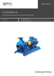
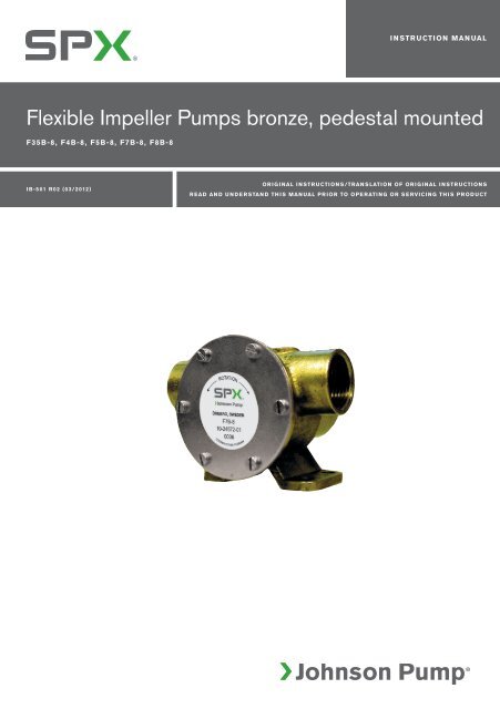
<strong>Flexible</strong> <strong>Impeller</strong> <strong><strong>Pump</strong>s</strong> <strong>bronze</strong>, <strong>pedestal</strong> <strong>mounted</strong><br />
F35B-8, F4B-8, F5B-8, F7B-8, F8B-8<br />
IB-501 R02 (03/2012)<br />
ORIGINAL INSTRUCTIONS/TRANSLATION OF ORIGINAL INSTRUCTIONS<br />
READ AND UNDERSTAND THIS MANUAL PRIOR TO OPERATING OR SERVICING THIS PRODUCT
INDEX - INDICE<br />
Svenska........................................................................................................................................3<br />
English....................................................................................................................................... 10<br />
Deutsch..................................................................................................................................... 17<br />
Français.....................................................................................................................................24<br />
Español......................................................................................................................................31<br />
Italiano.......................................................................................................................................38<br />
Besök www.johnson-pump.com för mer information om vår världsomspännande organisation, våra godkännanden, certifieringar och lokala representanter. SPX<br />
Corporation förbehåller sig rätten att ändra design och material utan föregående avisering. Designelement, konstruktionsmaterial och dimensioner som beskrivs i denna<br />
bulletin gäller endast som information och skall alltid bekräftas skriftligt för att vara gällande.<br />
For more information about our worldwide locations, approvals, certifications, and local representatives, please visit www.johnson-pump.com. SPX Corporation<br />
reserves the right to incorporate our latest design and material changes without notice or obligation. Design features, materials of construction and dimensional data,<br />
as described in this bulletin, are provided for your information only and should not be relied upon unless confirmed in writing.<br />
Für weitere Informationen über unsere weltweiten Standorte, Zulassungen, Zertifizierungen und unsere Vertreter vor Ort, besuchen Sie bitte unsere Webseite:<br />
www.johnson-pump.com. Die SPX Corporation behält sich das Recht vor, die neuesten Konstruktions- und Werkstoffänderungen ohne vorherige Ankündigung und<br />
ohne Verpflichtung hierzu einfließen zu lassen. Konstruktive Ausgestaltungen, Werkstoffe sowie Maßangaben, wie sie in dieser Mitteilung beschrieben sind, sind nur zur<br />
Information. Alle Angaben sind unverbindlich, es sei denn, sie wurden schriftlich bestätigt.<br />
Pour plus d’information sur nos succursales internationales, nos approbations, nos certifications et nos représentants locaux, veuillez consulter notre site Internet au<br />
www.johnson-pump.com. SPX Corporation se réserve le droit d’incorporer nos plus récents concepts ainsi que tout autre modification importante sans préavis ou<br />
obligation. Les éléments décoratifs, matériaux de construction et les données dimensionnelles, tels qu’énoncés dans ce communiqué, sont fournis pour votre information<br />
seulement et ne doivent pas être considérés comme officiels à moins d’avis contraire par écrit.<br />
Para más información sobre nuestras oficinas a nivel mundial, aprobaciones, certificaciones y representantes locales, por favor visite www.johnson-pump.com. SPX<br />
Corporation se reserva el derecho de incorporar nuestro diseño más reciente y cambios materiales sin necesidad de notificación previa u obligación de ningún tipo.<br />
Características de diseño, materiales de construcción y dimensiones, tal y como están descritas en este boletín, son proporcionadas sólo con fines informativos y no<br />
deben ser usados como referencia a menos que sean confirmados por escrito.<br />
Per ottenere maggiori informazioni sulle nostre sedi nel mondo, autorizzazioni, certificazioni, e rappresentanti locali, potete visitare il sito www.johnson-pump.com.<br />
La SPX Corporation si riserva il diritto di apportare cambiamenti ai propri design e materiali senza preavviso o vincolo. Le caratteristiche del design, i materiali di<br />
costruzione e i dati dimensionali, così come descritti nel presente bollettino, sono forniti solo per vostra informazione e non saranno oggetto di obbligazione salvo<br />
autorizzazione confermata per iscritto.<br />
Made in Sweden<br />
Garanti 1 år<br />
Warranty 1 year<br />
Garantie 1 Jahr<br />
Garantie 1 an<br />
Garantía 1 año<br />
Garanzia 1 anno
Svenska<br />
Självsugande flexibel impellerpump i brons,<br />
fotmonterad<br />
Typiska användningsområden<br />
• Marint<br />
Kylvattenpump, länspump, spolpump,<br />
tömning av septiktankar.<br />
• Industri och jordbruk<br />
Transport- och cirkulationspump, tömning<br />
av slam- och spillvätskebrunnar,<br />
pumpning av förorenade vätskor innehållande<br />
fasta partiklar.<br />
Teknisk beskrivning<br />
<strong>Pump</strong>hus: Brons<br />
<strong>Impeller</strong>: Neopren, EPDM alt nitril<br />
Axel: Syrafast stål<br />
Axeln är lagrad i två permanentsmorda<br />
dubbla kullager<br />
Tätning: Läpptätning alt.<br />
mekanisk tätning<br />
Kam: Hel alt reducerad<br />
Anslutning: Se "Modellspecifikation",<br />
sid 4<br />
Tryck- och kapacitetsdata<br />
Se sid 45-47<br />
Serviceinstruktion<br />
Se reservdelslista sid 5-9<br />
Demontering<br />
1. Lossa pumplocket och tag bort o-ringen<br />
2. Tag ur impellern med t ex två skruvmejslar.<br />
3. Demontera kammen och tag bort tätningsmedlet<br />
på kammen och i pumphuset.<br />
Tag även bort slitbrickan.<br />
4. Demontera läpptätningen alt. mekaniska<br />
tätningen.<br />
5. Demontera brickan (pos 9 för F35B-8<br />
- F7B-8 resp pos 10 för F8B-8) genom<br />
att slå in en mejsel genom urgjutningen<br />
och bänd ut brickan.<br />
6. Demontera låsringen som håller lagerpaketet.<br />
7. Demontera axeln med kullager genom<br />
att pressa på axeländen från impellersidan.<br />
8. Demontera kullagren/låsringen och<br />
distanshylsan. På F35B-8, F4B-8 och<br />
F8B-8 får inte kullagren pressas över<br />
tätningsytan.<br />
9. Tag bort O-ringen på axeln.<br />
Montering<br />
1. Montera kullagren/låsringen och distanshylsan<br />
på axeln. På F35B-8, F4B-8<br />
och F8B-8 får inte lagren pressas över<br />
tätningsytan.<br />
2. Montera O-ringen på axeln (gäller ej<br />
F8B-8).<br />
3. Pressa i axeln med kullagren i pumphuset<br />
och montera låsringen samt bricka<br />
(pos 9 för F35B-8 - F7B-8 resp pos 10<br />
för F8B-8). Montera O-ringen pos 21<br />
(gäller endast F8B-8)<br />
4. Montera läpptätningen (fjädern i läpptätningnen<br />
ska vara vänd mot impellern) alt<br />
mekaniska tätningen. Montera slitbrickan.<br />
5. Skruva fast kammen, men lägg först på<br />
tätningsmedel på kam och kamskruv för<br />
att förhindra läckage.<br />
6. Smörj impellern med JP <strong>Impeller</strong> Lubricant<br />
och montera med roterande rörelse<br />
i impellerns rotationsriktning.<br />
7. Montera O-ringen och skruva fast<br />
locket.<br />
Avfallshantering/<br />
materialåtervinning<br />
Vid avfallshantering ska produkten lämnas<br />
för destruktion/återvinning enligt gällande<br />
lagstiftning. Vid tillämpliga fall demonteras<br />
och sorteras produkten i ingående materialfraktioner.<br />
Översättning av originalinstruktionerna<br />
3
Svenska<br />
Modellspecifikation<br />
F35B-8 Order Nr. Order Nr.<br />
<strong>Pump</strong> typ Läpptätning Mek.tätning <strong>Impeller</strong> Kam <strong>Pump</strong>hus Anslutning<br />
F35B-8 10-24569-13 10-24569-01 Neopren 1 01-35881-1 ISO7/1-Rp3/8<br />
F35B-802 10-24569-15 10-24569-03 Neopren 1/2 01-35881-1 ISO7/1-Rp3/8<br />
F35B-8007 10-24569-52 10-24569-51 Neopren 1 01-35881-2 3/8-18NPTF<br />
F35B-8027 10-24569-21 10-24569-09 Neopren 1/2 01-35881-2 3/8-18NPTF<br />
F4B-8 Order Nr. Order Nr.<br />
<strong>Pump</strong> typ Läpptätning Mek.tätning <strong>Impeller</strong> Kam <strong>Pump</strong>hus Anslutning<br />
F4B-8 10-24570-13 10-24570-01 Neopren 1 01-35882-1 ISO7/1-Rp3/8<br />
F4B-89 10-24570-14 10-24570-02 Nitril 1 01-35882-1 ISO7/1-Rp3/8<br />
F4B-8007 10-24570-19 10-24570-07 Neopren 1 01-35882-2 3/8-18NPTF<br />
F4B-8007 10-24570-52 10-24570-51 Neopren 1 01-35882-2 3/8-18NPTF<br />
F5B-8 Order Nr. Order Nr.<br />
<strong>Pump</strong> typ Läpptätning Mek.tätning <strong>Impeller</strong> Kam <strong>Pump</strong>hus Anslutning<br />
F5B-8 10-24571-13 10-24571-01 Neopren 1 01-24573-1 ISO7/1-Rp3/4<br />
F5B-89 10-24571-14 10-24571-02 Nitril 1 01-24573-1 ISO7/1-Rp3/4<br />
F5B-802 10-24571-15 10-24571-03 Neopren 1/2 01-24573-1 ISO7/1-Rp3/4<br />
F5B-8007 10-24571-52 10-24571-51 Neopren 1 01-24573-2 3/4-14NPTF<br />
F7B-8 Order Nr. Order Nr.<br />
<strong>Pump</strong> typ Läpptätning Mek.tätning <strong>Impeller</strong> Kam <strong>Pump</strong>hus Anslutning<br />
F7B-8 10-24572-13 10-24572-01 EPDM 1 01-24574-3 ISO7/1-Rp1<br />
F7B-8007 10-24572-52 10-24572-51 EPDM 1 01-24574-4 1-11<br />
1/2NPTF<br />
F8B-8 Order Nr. Order Nr.<br />
<strong>Pump</strong> typ Läpptätning Mek.tätning <strong>Impeller</strong> Kam <strong>Pump</strong>hus Anslutning<br />
F8B-8 10-13021-1 Neopren 1 01-13164-1 ISO7/1-Rp11/2<br />
F8B-8007 10-13021-9 Neopren 1 01-13164-2 11/2-111/2NPTF<br />
F8B-8007 10-13021-95 Neopren 1 01-13164-3 11/4-111/2NPTF<br />
F8B-8007 10-13021-96 Neopren 1 01-13164-4 11/2-<br />
111/2NPTF<br />
4 Översättning av originalinstruktionerna
Svenska<br />
Reservdelslista 22<br />
F35B-8<br />
Pos Antal Benämning 10-24569-13 10-24569-15 10-24569-52 10-24569-21 Läpptätning<br />
10-24569-01 10-24569-03 10-24569-51 10-24569-09 Mektätning<br />
1 1 <strong>Pump</strong>hus 01-35881-1 01-35881-1 01-35881-2 01-35881-2<br />
2 1 Axel 01-46735-1 01-46735-1 01-46740 01-46735-1<br />
3 1 Lock 01-46739-2 01-46739-2 01-46739-2 01-46739-2<br />
4 1 <strong>Impeller</strong> 09-808B 09-808B 09-808B 09-808B<br />
5 1 Kam 01-42910 01-42415 01-42910 01-42415<br />
6 1 Distansring 01-45542 01-45542 01-45542 01-45542<br />
7 1 Stift 01-42400 01-42400 01-42400 01-42400<br />
8 1 Slitbricka 01-46676 01-46676 01-46676 01-46676<br />
9 1 Bricka 01-45049 01-45049 01-45049 01-45049<br />
10 1 Bricka 01-45659 01-45659 01-45659 01-45659<br />
12 1 Bricka 01-46790-01 01-46790-01 01-46790-01 01-46790-01<br />
14 4 Skruv 0.0279.300 0.0279.300 0.0279.300 0.0279.300<br />
15 1 Skruv 01-46974-03 01-46794-10 01-46794-03 01-46794-10<br />
16 1 O-ring 0.2173.440 0.2173.440 0.2173.440 0.2173.440<br />
17 1 O-ring 0.2173.432 0.2173.432 0.2173.432 0.2173.432<br />
18 2 Kullager 0.3431.748 0.3431.748 0.3431.748 0.3431.748<br />
19 1 Läpptätning 0.2233.010 0.2233.010 0.2233.010 0.2233.010<br />
19 1 Mek.tätning 0.2247.021 0.2247.021 0.2247.021 0.2247.021<br />
20 1 Låsring 0.0371.028 0.0371.028 0.0371.028 0.0371.028<br />
21 1 Låsring 0.0370.012 0.0370.012 0.0370.012 0.0370.012<br />
22 1 Låsring 0.0370.512 0.0370.512 0.0370.512 0.0370.512<br />
Reservdelssats:<br />
4,14,16&19 09-45589 09-45589 09-45589 09-45589 Läpptätning<br />
4,14,16&19 09-46840 09-46840 09-46840 09-46840 Mek.tätning<br />
Översättning av originalinstruktionerna<br />
5
Svenska<br />
Reservdelslista<br />
22<br />
F4B-8<br />
Pos Antal Benämning 10-24570-13 10-24570-14 10-24570-19 10-24570-52 Läpptätning<br />
10-24570-01 10-24570-02 10-24570-07 10-24570-51 Mektätning<br />
1 1 <strong>Pump</strong>hus 01-35882-1 01-35882-1 01-35882-2 01-35882-2<br />
2 1 Axel 01-46735-1 01-46735-1 01-46735-1 01-46740<br />
3 1 Lock 01-46007-2 01-46007-2 01-46007-2 01-46007-2<br />
4 1 <strong>Impeller</strong> 09-810B 09-810B-9 09-810B 09-810B<br />
5 1 Kam 01-42389 01-42389 01-42389 01-42389<br />
6 1 Distansring 01-45542 01-45542 01-45542 01-45542<br />
7 1 Stift 01-42400 01-42400 01-42400 01-42400<br />
8 1 Slitbricka 01-46737-2 01-46737-2 01-46737-2 01-46737-2<br />
9 1 Bricka 01-45049 01-45049 01-45049 01-45049<br />
10 1 Bricka 01-45659 01-45659 01-45659 01-45659<br />
12 1 Bricka 01-46790-01 01-46790-01 01-46790-01 01-46790-01<br />
14 6 Skruv 0.0279.300 0.0279.300 0.0279.300 0.0279.300<br />
15 1 Skruv 01-46794-04 01-46794-04 01-46794-04 01-46794-04<br />
16 1 O-ring 0.2173.476 0.2173.476 0.2173.476 0.2173.476<br />
17 1 O-ring 0.2173.432 0.2173.432 0.2173.432 0.2173.432<br />
18 2 Kullager 0.3431.748 0.3431.748 0.3431.748 0.3431.748<br />
19 1 Läpptätning 0.2233.010 0.2233.010 0.2233.010 0.2233.010<br />
19 1 Mek.tätning 0.2247.021 0.2247.021 0.2247.021 0.2247.021<br />
20 1 Låsring 0.0371.028 0.0371.028 0.0371.028 0.0371.028<br />
21 1 Låsring 0.0370.012 0.0370.012 0.0370.012 0.0370.012<br />
22 1 Låsring 0.0370.512 0.0370.512 0.0370.512 0.0370.512<br />
Reservdelssats:<br />
4,14,16 & 19 09-45587 09-45588 09-45587 09-45587 Läpptätning<br />
4,14,16 & 19 09-46841 09-46842 09-46841 09-46841 Mek.tätning<br />
6 Översättning av originalinstruktionerna
Svenska<br />
Reservdelslista<br />
F5B-8<br />
Pos Antal Benämning 10-24571-13 10-24571-14 10-24571-15 10-24571-52 Läpptätning<br />
10-24571-01 10-24571-02 10-24571-03 10-24571-51 Mek.tätning<br />
1 1 <strong>Pump</strong>hus 01-24573-1 01-24573-1 01-24573-1 01-24573-2<br />
2 1 Axel 01-46744 01-46744 01-46744 01-46746<br />
3 1 Lock 01-46747-2 01-46747-2 01-46747-2 01-46747-2<br />
4 1 <strong>Impeller</strong> 09-1027B 09-1027B-9 09-1027B 09-1027B<br />
5 1 Kam 01-42397 01-42397 01-45014 01-42397<br />
6 1 Stift 01-42400 01-42400 01-42400 01-42400<br />
7 1 Slitbricka 01-42399-2 01-42399-2 01-42399-2 01-42399-2<br />
8 1 Bricka 01-45680 01-45680 01-45680 01-45680<br />
9 1 Bricka 01-45047 01-45047 01-45047 01-45047<br />
10 1 Distansring 01-46009 01-46009 01-46009 01-46009<br />
11 6 Skruv 0.0279.300 0.0279.300 0.0279.300 0.0279.300<br />
12 1 Skruv 01-46794-05 01-46794-05 0.0279.032 01-46794-05<br />
13 1 O-ring 0.2173.475 0.2173.475 0.2173.475 0.2173.475<br />
14 1 O-ring 0.2173.402 0.2173.402 0.2173.402 0.2173.402<br />
15 2 Kullager 0.3431.742 0.3431.742 0.3431.742 0.3431.742<br />
16 1 Läpptätning 0.2233.012 0.2233.012 0.2233.012 0.2233.012<br />
16 1 Mek.tätning 0.2247.022 0.2247.022 0.2247.022 0.2247.022<br />
17 1 Låsring 0.0371.040 0.0371.040 0.0371.040 0.0371.040<br />
18 1 Låsring 0.0370.017 0.0370.017 0.0370.017 0.0370.017<br />
19 1 Låsring 0.0370.516 0.0370.516 0.0370.516 0.0370.516<br />
Reservdelssats:<br />
4,11,13 & 16 09-45585 09-45586 09-45585 09-45585 Läpptätning<br />
4,11,13 & 16 09-46843 09-46844 09-46843 09-46843 Mektätning<br />
Översättning av originalinstruktionerna<br />
7
Svenska<br />
Reservdelslista<br />
F7B-8<br />
Pos Antal Benämning 10-24572-13 10-24572-52 Läpptätning<br />
10-24572-01 10-24572-51 Mek.tätning<br />
1 1 <strong>Pump</strong>hus 01-24574-3 01-24574-4<br />
2 1 Axel 01-46744 01-46746<br />
3 1 Lock 01-46648-3 01-46648-3<br />
4 1 <strong>Impeller</strong> 09-1028BT-1 09-1028BT-1<br />
5 1 Kam 01-42679 01-42679<br />
6 1 Stift 01-42400 01-42400<br />
7 1 Slitbricka 01-46798-2 01-46798-2<br />
8 1 Bricka 01-45680 01-45680<br />
9 1 Bricka 01-45047 01-45047<br />
10 1 Distansring 01-46009 01-46009<br />
11 6 Skruv 0.0279.301 0.0279.301<br />
12 1 Skruv 01-46794-01 01-46794-01<br />
13 1 O-ring 0.2172.012 0.2172.012<br />
14 1 O-ring 0.2173.402 0.2173.402<br />
15 2 Kullager 0.3431.742 0.3431.742<br />
16 1 Läpptätning 0.2233.012 0.2233.012<br />
16 1 Mek.tätning 0.2247.022 0.2247.022<br />
17 1 Låsring 0.0371.040 0.0371.040<br />
18 1 Låsring 0.0370.017 0.0370.017<br />
19 1 Låsring 0.0370.516 0.0370.516<br />
Reservdelssats:<br />
4,11,13 & 16 09-47426 09-47426 Läpptätning<br />
4,11,13 & 16 09-47427 09-47427 Mek.tätning<br />
8 Översättning av originalinstruktionerna
Svenska<br />
Reservdelslista<br />
8007<br />
F8B-8 F8B-8007 F8B-8007 F8B-<br />
Pos Antal Benämning 10-13021-1 10-13021-9 10-13021-95 10-13021-96<br />
1 1 <strong>Pump</strong>hus 01-13164-1 01-13164-2 01-13164-3 01-13164-4<br />
2 1 Axel 01-35132 01-35132 01-35746 01-35746<br />
3 1 Kam 01-42680 01-42680 01-42680 01-42680<br />
4 1 <strong>Impeller</strong> 09-819B 09-819B 09-819B 09-819B<br />
5 1 Lock 01-42422-1 01-42422-1 01-42422-1 01-42422-1<br />
6 1 Packning 01-42424 01-42424 01-42424 01-42424<br />
7 1 Slitbricka 01-42423 01-42423 01-42423 01-42423<br />
8 1 Stift 01-42426 01-42426 01-42426 01-42426<br />
9 1 Distansring 01-45374 01-45374 01-45374 01-45374<br />
10 1 Bricka 01-45380 01-45380 01-45380 01-45380<br />
11 2 Kullager 0.3431.780 0.3431.780 0.3431.780 0.3431.780<br />
12 1 Låsring 0.0371.062 0.0371.062 0.0371.062 0.0371.062<br />
13 5 Skruv 0.0138.134 0.0138.134 0.0138.134 0.0138.134<br />
14 1 Skruv 01-46794-02 01-46794-02 01-46794-02 01-46794-02<br />
15 1 Kil 0.0502.231 0.0502.231 - -<br />
17 1 Mek.tätning 0.2247.008 0.2247.008 0.2247.008 0.2247.008<br />
18 2 Låsring 0.0370.525 0.0370.525 0.0370.525 0.0370.525<br />
21 1 O-ring 0.2172.573 0.2172.573 0.2172.573 0.2172.573<br />
Reservdelssats:<br />
4,6,13,17 & 18 09-45575 09-45575 09-45575 09-45575<br />
Översättning av originalinstruktionerna<br />
9
English<br />
Self-priming, flexible impeller pump of <strong>bronze</strong>,<br />
<strong>pedestal</strong> <strong>mounted</strong><br />
Typical applications<br />
• Marine<br />
Engine cooling, bilge pump, deck-wash<br />
pump, wash-down, emptying holding<br />
tanks.<br />
• Industry<br />
Liquid circulation and transfer, emptying<br />
tanks and sump drainage, handling of<br />
solids in suspension.<br />
Design features<br />
Body: Bronze<br />
<strong>Impeller</strong>: Neoprene, EPDM or nitrile<br />
Shaft: Stainless steel<br />
The shaft is <strong>mounted</strong><br />
with two permanently<br />
lubricated double ball<br />
bearings<br />
Seal: Lip seal alt. mechanical seal<br />
Cam: Full or reduced<br />
Connection: See "Type designation",<br />
page 11<br />
Pressure and capacity data<br />
See page 45-47<br />
Service instructions<br />
See parts list page 12-16.<br />
Disassembly<br />
1. Remove the endcover and the o-ring.<br />
2. Pull out the impeller using two screw<br />
drivers or other suitable implements.<br />
3. Remove the cam and wash away any<br />
traces of sealing compound on the cam<br />
and inside the pump body. Remove the<br />
wear plate.<br />
4. Remove the lip seal alt mechanical seal.<br />
5. Remove the washer (pos 9 for F35B-<br />
8 - F7B-8 and pos 10 for F8B-8) by<br />
inserting a screw driver through the slot<br />
and lever out the washer.<br />
6. Remove the retaining ring for the bearing<br />
assembly.<br />
7. Remove the shaft with ball bearings<br />
by pressing on the shaft end from the<br />
impeller side.<br />
8. Remove the ball bearings/retaining ring<br />
and the spacer. On F35B-8, F4B-8 and<br />
F8B-8 do not press the ball bearings<br />
over the sealing surface.<br />
9. Remove the O-ring from the shaft.<br />
Assembly<br />
1. Mount the ball bearings/retaining ring<br />
and the spacer on the shaft. On F35B-<br />
8, F4B-8 and F8B-8 do not press the<br />
ball bearings over the sealing surface.<br />
2. Mount the O-ring on the shaft (not on<br />
F8B-8)<br />
3. Press the shaft with ball bearings into<br />
the body and fit the retaining ring and<br />
washer (pos 9 for F35B-8 - F7B-8 and<br />
pos 10 for F8B-8). Mount the o-ring pos<br />
21 (only on the F8B-8).<br />
4. Mount the lip seal (spring towards the<br />
impeller) alt mechanical seal. Mount the<br />
wear plate (pos 18).<br />
5. Fasten the cam, but before doing so<br />
apply sealing compound to cam and<br />
screw in order to prevent leakage.<br />
6. Lubricate the impeller with JP <strong>Impeller</strong><br />
Lubricant and fit it wit a rotating<br />
movement in the intended direction of<br />
rotation.<br />
7. Fit the O-ring before mounting the endcover.<br />
Waste handling<br />
material recycling<br />
At the products end of life, please dispose<br />
of the product according to applicable law.<br />
Where applicable, please disassemble the<br />
product and recycle the parts material.<br />
10 Original instructions
English<br />
Type designation<br />
F35B-8 Part No. Part No.<br />
<strong>Pump</strong> type Lipseal Mechanical seal <strong>Impeller</strong> Cam Body Connection<br />
F35B-8 10-24569-13 10-24569-01 Neopren 1 01-35881-1 ISO7/1-Rp3/8<br />
F35B-802 10-24569-15 10-24569-03 Neopren 1/2 01-35881-1 ISO7/1-Rp3/8<br />
F35B-8007 10-24569-52 10-24569-51 Neopren 1 01-35881-2 3/8-18NPTF<br />
F35B-8027 10-24569-21 10-24569-09 Neopren 1/2 01-35881-2 3/8-<br />
18NPTF<br />
F4B-8 Part No. Part No.<br />
<strong>Pump</strong> type Lipseal Mechanical seal <strong>Impeller</strong> Cam Body Connection<br />
F4B-8 10-24570-13 10-24570-01 Neopren 1 01-35882-1 ISO7/1-Rp3/8<br />
F4B-89 10-24570-14 10-24570-02 Nitril 1 01-35882-1 ISO7/1-Rp3/8<br />
F4B-8007 10-24570-19 10-24570-07 Neopren 1 01-35882-2 3/8-18NPTF<br />
F4B-8007 10-24570-52 10-24570-51 Neopren 1 01-35882-2 3/8-<br />
18NPTF<br />
F5B-8 Part No. Part No.<br />
<strong>Pump</strong> type Lipseal Mechanical seal <strong>Impeller</strong> Cam Body Connection<br />
F5B-8 10-24571-13 10-24571-01 Neopren 1 01-24573-1 ISO7/1-Rp3/4<br />
F5B-89 10-24571-14 10-24571-02 Nitril 1 01-24573-1 ISO7/1-Rp3/4<br />
F5B-802 10-24571-15 10-24571-03 Neopren 1/2 01-24573-1 ISO7/1-Rp3/4<br />
F5B-8007 10-24571-52 10-24571-51 Neopren 1 01-24573-2 3/4-<br />
14NPTF<br />
F7B-8 Part No. Part No.<br />
<strong>Pump</strong> type Lipseal Mechanical seal <strong>Impeller</strong> Cam Body Connection<br />
F7B-8 10-24572-13 10-24572-01 EPDM 1 01-24574-3 ISO7/1-Rp1<br />
F7B-8007 10-24572-52 10-24572-51 EPDM 1 01-24574-4 1-11 1/2NPTF<br />
F8B-8 Part No. Part No.<br />
<strong>Pump</strong> type Lipseal Mechanical seal <strong>Impeller</strong> Cam Body Connection<br />
F8B-8 10-13021-1 Neopren 1 01-13164-1 ISO7/1-Rp11/2<br />
F8B-8007 10-13021-9 Neopren 1 01-13164-2 11/2-111/2NPTF<br />
F8B-8007 10-13021-95 Neopren 1 01-13164-3 11/4-111/2NPTF<br />
F8B-8007 10-13021-96 Neopren 1 01-13164-4 11/2-<br />
111/2NPTF<br />
Original instructions<br />
11
English<br />
Parts list 22<br />
F35B-8<br />
Pos Nos Description 10-24569-13 10-24569-15 10-24569-52 10-24569-21 Lipseal<br />
10-24569-01 10-24569-03 10-24569-51 10-24569-09 Mech. seal<br />
1 1 Body 01-35881-1 01-35881-1 01-35881-2 01-35881-2<br />
2 1 Shaft 01-46735-1 01-46735-1 01-46740 01-46735-1<br />
3 1 Endcover 01-46739-2 01-46739-2 01-46739-2 01-46739-2<br />
4 1 <strong>Impeller</strong> 09-808B 09-808B 09-808B 09-808B<br />
5 1 Cam 01-42910 01-42415 01-42910 01-42415<br />
6 1 Spacer 01-45542 01-45542 01-45542 01-45542<br />
7 1 Pin 01-42400 01-42400 01-42400 01-42400<br />
8 1 Wear plate 01-46676 01-46676 01-46676 01-46676<br />
9 1 Washer 01-45049 01-45049 01-45049 01-45049<br />
10 1 Washer 01-45659 01-45659 01-45659 01-45659<br />
12 1 Washer 01-46790-01 01-46790-01 01-46790-01 01-46790-01<br />
14 4 Screw 0.0279.300 0.0279.300 0.0279.300 0.0279.300<br />
15 1 Screw 01-46974-03 01-46794-10 01-46794-03 01-46794-10<br />
16 1 O-ring 0.2173.440 0.2173.440 0.2173.440 0.2173.440<br />
17 1 O-ring 0.2173.432 0.2173.432 0.2173.432 0.2173.432<br />
18 2 Ball bearing 0.3431.748 0.3431.748 0.3431.748 0.3431.748<br />
19 1 Lipseal 0.2233.010 0.2233.010 0.2233.010 0.2233.010<br />
19 1 Mech. seal 0.2247.021 0.2247.021 0.2247.021 0.2247.021<br />
20 1 Retainingring 0.0371.028 0.0371.028 0.0371.028 0.0371.028<br />
21 1 Retainingring 0.0370.012 0.0370.012 0.0370.012 0.0370.012<br />
22 1 Retainingring 0.0370.512 0.0370.512 0.0370.512 0.0370.512<br />
Spareparts kit:<br />
4,14,16&19 09-45589 09-45589 09-45589 09-45589 Lipseal<br />
4,14,16&19 09-46840 09-46840 09-46840 09-46840 Mech. seal<br />
12 Original instructions
English<br />
Parts list<br />
22<br />
F4B-8<br />
Pos Nos Description 10-24570-13 10-24570-14 10-24570-19 10-24570-52 Lipseal<br />
10-24570-01 10-24570-02 10-24570-07 10-24570-51 Mech. seal<br />
1 1 Body 01-35882-1 01-35882-1 01-35882-2 01-35882-2<br />
2 1 Shaft 01-46735-1 01-46735-1 01-46735-1 01-46740<br />
3 1 Endcover 01-46007-2 01-46007-2 01-46007-2 01-46007-2<br />
4 1 <strong>Impeller</strong> 09-810B 09-810B-9 09-810B 09-810B<br />
5 1 Cam 01-42389 01-42389 01-42389 01-42389<br />
6 1 Spacer 01-45542 01-45542 01-45542 01-45542<br />
7 1 Pin 01-42400 01-42400 01-42400 01-42400<br />
8 1 Wearplate 01-46737-2 01-46737-2 01-46737-2 01-46737-2<br />
9 1 Washer 01-45049 01-45049 01-45049 01-45049<br />
10 1 Washer 01-45659 01-45659 01-45659 01-45659<br />
12 1 Washer 01-46790-01 01-46790-01 01-46790-01 01-46790-01<br />
14 6 Screw 0.0279.300 0.0279.300 0.0279.300 0.0279.300<br />
15 1 Screw 01-46794-04 01-46794-04 01-46794-04 01-46794-04<br />
16 1 O-ring 0.2173.476 0.2173.476 0.2173.476 0.2173.476<br />
17 1 O-ring 0.2173.432 0.2173.432 0.2173.432 0.2173.432<br />
18 2 Ball bearing 0.3431.748 0.3431.748 0.3431.748 0.3431.748<br />
19 1 Lipseal 0.2233.010 0.2233.010 0.2233.010 0.2233.010<br />
19 1 Mech. seal 0.2247.021 0.2247.021 0.2247.021 0.2247.021<br />
20 1 Retaining ring 0.0371.028 0.0371.028 0.0371.028 0.0371.028<br />
21 1 Retaining ring 0.0370.012 0.0370.012 0.0370.012 0.0370.012<br />
22 1 Retaining ring 0.0370.512 0.0370.512 0.0370.512 0.0370.512<br />
Spareparts kit:<br />
4,14,16 & 19 09-45587 09-45588 09-45587 09-45587 Lipseal<br />
4,14,16 & 19 09-46841 09-46842 09-46841 09-46841 Mech. seal<br />
Original instructions<br />
13
English<br />
Parts list<br />
F5B-8<br />
Pos Nos Description 10-24571-13 10-24571-14 10-24571-15 10-24571-52 Lipseal<br />
10-24571-01 10-24571-02 10-24571-03 10-24571-51 Mech. seal<br />
1 1 Body 01-24573-1 01-24573-1 01-24573-1 01-24573-2<br />
2 1 Shaft 01-46744 01-46744 01-46744 01-46746<br />
3 1 Endcover 01-46747-2 01-46747-2 01-46747-2 01-46747-2<br />
4 1 <strong>Impeller</strong> 09-1027B 09-1027B-9 09-1027B 09-1027B<br />
5 1 Cam 01-42397 01-42397 01-45014 01-42397<br />
6 1 Pin 01-42400 01-42400 01-42400 01-42400<br />
7 1 Wearplate 01-42399-2 01-42399-2 01-42399-2 01-42399-2<br />
8 1 Washer 01-45680 01-45680 01-45680 01-45680<br />
9 1 Washer 01-45047 01-45047 01-45047 01-45047<br />
10 1 Spacer 01-46009 01-46009 01-46009 01-46009<br />
11 6 Screw 0.0279.300 0.0279.300 0.0279.300 0.0279.300<br />
12 1 Screw 01-46794-05 01-46794-05 0.0279.032 01-46794-05<br />
13 1 O-ring 0.2173.475 0.2173.475 0.2173.475 0.2173.475<br />
14 1 O-ring 0.2173.402 0.2173.402 0.2173.402 0.2173.402<br />
15 2 Ball bearing 0.3431.742 0.3431.742 0.3431.742 0.3431.742<br />
16 1 Lipseal 0.2233.012 0.2233.012 0.2233.012 0.2233.012<br />
16 1 Mech. seal 0.2247.022 0.2247.022 0.2247.022 0.2247.022<br />
17 1 Retaining ring 0.0371.040 0.0371.040 0.0371.040 0.0371.040<br />
18 1 Retaining ring 0.0370.017 0.0370.017 0.0370.017 0.0370.017<br />
19 1 Retaining ring 0.0370.516 0.0370.516 0.0370.516 0.0370.516<br />
Spareparts kit:<br />
4,11,13 & 16 09-45585 09-45586 09-45585 09-45585 Lipseal<br />
4,11,13 & 16 09-46843 09-46844 09-46843 09-46843 Mech. seal<br />
14 Original instructions
English<br />
Parts list<br />
F7B-8<br />
Pos Nos Benämning 10-24572-13 10-24572-52 Lipseal<br />
10-24572-01 10-24572-51 Mech. seal<br />
1 1 Body 01-24574-3 01-24574-4<br />
2 1 Shaft 01-46744 01-46746<br />
3 1 Endcover 01-46648-3 01-46648-3<br />
4 1 <strong>Impeller</strong> 09-1028BT-1 09-1028BT-1<br />
5 1 Cam 01-42679 01-42679<br />
6 1 Pin 01-42400 01-42400<br />
7 1 Wearplate 01-46798-2 01-46798-2<br />
8 1 Washer 01-45680 01-45680<br />
9 1 Washer 01-45047 01-45047<br />
10 1 Spacer 01-46009 01-46009<br />
11 6 Screw 0.0279.301 0.0279.301<br />
12 1 Screw 01-46794-01 01-46794-01<br />
13 1 O-ring 0.2172.012 0.2172.012<br />
14 1 O-ring 0.2173.402 0.2173.402<br />
15 2 Ball bearing 0.3431.742 0.3431.742<br />
16 1 Lipseal 0.2233.012 0.2233.012<br />
16 1 Mech. seal 0.2247.022 0.2247.022<br />
17 1 Retaining ring 0.0371.040 0.0371.040<br />
18 1 Retaining ring 0.0370.017 0.0370.017<br />
19 1 Retaining ring 0.0370.516 0.0370.516<br />
Spareparts kit:<br />
4,11,13 & 16 09-47426 09-47426 Lipseal<br />
4,11,13 & 16 09-47427 09-47427 Mech. seal<br />
Original instructions<br />
15
English<br />
Parts list<br />
F8B-8 F8B-8007 F8B-8007 F8B-<br />
8007<br />
Pos Nos Description 10-13021-1 10-13021-9 10-13021-95 10-13021-96<br />
1 1 Body 01-13164-1 01-13164-2 01-13164-3 01-13164-42<br />
1 Shaft 01-35132 01-35132 01-35746 01-35746<br />
3 1 Cam 01-42680 01-42680 01-42680 01-42680<br />
4 1 <strong>Impeller</strong> 09-819B 09-819B 09-819B 09-819B<br />
5 1 Endcover 01-42422-1 01-42422-1 01-42422-1 01-42422-1<br />
6 1 Gasket 01-42424 01-42424 01-42424 01-42424<br />
7 1 Wear plate 01-42423 01-42423 01-42423 01-42423<br />
8 1 Pin 01-42426 01-42426 01-42426 01-42426<br />
9 1 Spacer 01-45374 01-45374 01-45374 01-45374<br />
10 1 Washer 01-45380 01-45380 01-45380 01-45380<br />
11 2 Ball bearing 0.3431.780 0.3431.780 0.3431.780 0.3431.780<br />
12 1 Retaining ring 0.0371.062 0.0371.062 0.0371.062 0.0371.062<br />
13 5 Screw 0.0138.134 0.0138.134 0.0138.134 0.0138.134<br />
14 1 Screw 01-46794-02 01-46794-02 01-46794-02 01-46794-<br />
02<br />
15 1 Key 0.0502.231 0.0502.231 - -<br />
17 1 Mech. seal 0.2247.008 0.2247.008 0.2247.008 0.2247.008<br />
18 2 Lipseal 0.0370.525 0.0370.525 0.0370.525 0.0370.525<br />
21 1 O-ring 0.2172.573 0.2172.573 0.2172.573 0.2172.573<br />
Spareparts kit:<br />
4,6,13,17 & 18 09-45575 09-45575 09-45575 09-45575<br />
16 Original instructions
Deutsch<br />
Selbstansaugende flexible <strong>Impeller</strong>pumpe aus<br />
Bronze, mit Lagerfuss<br />
Anwendungsbeispiele<br />
• Für den Marinesektor<br />
Kühlwasserpumpe für Motoren, Lenzpumpe,<br />
Spülpumpe, Entleerung von<br />
Fäkalientanks.<br />
• Für die Industrie<br />
Förder- und Umwälzpumpe, Entleerung<br />
von Schlamm- und Abflusschächten,<br />
<strong>Pump</strong>en von verunreinigten Flüssigkeiten<br />
mit festen Partikeln.<br />
Technische Beschreibung<br />
Gehäuse: Bronze<br />
<strong>Impeller</strong>: Neoprene, EPDM oder Nitrile<br />
Welle: Edelstahl, gelagert mit zwei<br />
dauergeschmierten Kugellagern<br />
Dichtung: Lippendichtung oder<br />
Gleitringdichtung<br />
Kamm: Voll oder reduzierter Kamm<br />
Anschluss: Siehe "Modellvarianten",<br />
Seite 18<br />
Druck und Leistungsdaten<br />
Siehe Seite 45-47.<br />
Bedienungsanleitungen<br />
Siehe Esatzteilliste Seite 19-23<br />
Demontage<br />
1. Den Deckel und den O-Ring entfernen.<br />
2. <strong>Impeller</strong> mit Hilfe von zwei Schraubenziehern<br />
herausdrücken.<br />
3. Nach Ausbau des Kamms Dichtungsreste<br />
vom <strong>Pump</strong>engehäuse und Kamm<br />
entfernen. Die Verschleißplatte entfernen.<br />
4. Die Lippendichtung oder die Gleitringdichtung<br />
entfernen.<br />
5. Die Scheibe (Pos. 9) entfernen, in dem<br />
ein Schraubendreher durch den Schlitz<br />
eingesteckt und damit die Scheibe<br />
herausgedrückt wird.<br />
Übersetzung der Original-Betriebsanleitungen<br />
6. Sicherungsring für das Lagerpaket<br />
abnehmen.<br />
7. Welle und Kugellager auspressen durch<br />
Druck auf die Welle von der <strong>Impeller</strong>seite<br />
her.<br />
8. Die Kugellager/den Sicherungsring und<br />
das Distanzstück entfernen. Bei F35B-8,<br />
F4B-8 und F8B-8 die Kugellager nicht<br />
über die Dichtfläche drücken.<br />
9. Den O-Ring von der Welle entfernen.<br />
Montage<br />
1. Die Kugellager/den Sicherungsring und<br />
das Distanzstück anbringen. Bei F35B-8,<br />
F4B-8 und F8B-8 die Kugellager nicht<br />
über die Dichtfläche drücken.<br />
2. Den O-Ring an die Welle anbringen<br />
(nicht bei F8B-8).<br />
3. Welle mit Kugellager in das <strong>Pump</strong>engehäuse<br />
pressen, Sicherungsring und<br />
Scheibe (Pos 9 für F35B-8 - F7B-8 und<br />
Pos 10 für F8B-8) montieren. Bei F8B-8<br />
den O-ring, Pos 21, anbringen .<br />
4. O-ring und Lippendichtung oder Gleitringdichtung<br />
einsetzen. Lippendichtung<br />
mit Öffnung zur <strong>Impeller</strong>seite hin. Die<br />
Verschleißplatte anbringen (Pos. 18).<br />
5. Kamm festschrauben. Auf Kamm und<br />
Schraube zuerst etwas Dichtungsmittel<br />
auftragen.<br />
6. <strong>Impeller</strong> einfetten (mit JP <strong>Impeller</strong> Lubricant)<br />
und in Drehrichtung des <strong>Impeller</strong>s<br />
montieren.<br />
7. Den O-Ring vor dem Anbringen des<br />
Deckels einsetzen.<br />
Entsorgung/Recycling<br />
Nach Lebensdauerende entsorgen Sie die<br />
<strong>Pump</strong>e nach den örtlichen Vorschriften.<br />
Nach Möglichkeit demontieren Sie Teile<br />
der <strong>Pump</strong>e um sie dem Recycling-Process<br />
zuzuführen.<br />
17
Deutsch<br />
Modellvarianten<br />
F35B-8 Artikel Nr. Artikel Nr.<br />
<strong>Pump</strong>e typ Lippendichtung Gleitringdichtung <strong>Impeller</strong> Kamm <strong>Pump</strong>engehäuse Anschluss<br />
F35B-8 10-24569-13 10-24569-01 Neopren 1 01-35881-1 ISO7/1-Rp3/8<br />
F35B-802 10-24569-15 10-24569-03 Neopren 1/2 01-35881-1 ISO7/1-Rp3/8<br />
F35B-8007 10-24569-52 10-24569-51 Neopren 1 01-35881-2 3/8-18NPTF<br />
F35B-8027 10-24569-21 10-24569-09 Neopren 1/2 01-35881-2 3/8-<br />
18NPTF<br />
F4B-8 Artikel Nr. Artikel Nr.<br />
<strong>Pump</strong>e typ Lippendichtung Gleitringdichtung <strong>Impeller</strong> Kamm <strong>Pump</strong>engehäuse Anschluss<br />
F4B-8 10-24570-13 10-24570-01 Neopren 1 01-35882-1 ISO7/1-Rp3/8<br />
F4B-89 10-24570-14 10-24570-02 Nitril 1 01-35882-1 ISO7/1-Rp3/8<br />
F4B-8007 10-24570-19 10-24570-07 Neopren 1 01-35882-2 3/8-18NPTF<br />
F4B-8007 10-24570-52 10-24570-51 Neopren 1 01-35882-2 3/8-<br />
18NPTF<br />
F5B-8 Artikel Nr. Artikel Nr.<br />
<strong>Pump</strong>e typ Lippendichtung Gleitringdichtung <strong>Impeller</strong> Kamm <strong>Pump</strong>engehäuse Anschluss<br />
F5B-8 10-24571-13 10-24571-01 Neopren 1 01-24573-1 ISO7/1-Rp3/4<br />
F5B-89 10-24571-14 10-24571-02 Nitril 1 01-24573-1 ISO7/1-Rp3/4<br />
F5B-802 10-24571-15 10-24571-03 Neopren 1/2 01-24573-1 ISO7/1-Rp3/4<br />
F5B-8007 10-24571-52 10-24571-51 Neopren 1 01-24573-2 3/4-<br />
14NPTF<br />
F7B-8 Artikel Nr. Artikel Nr.<br />
<strong>Pump</strong>e typ Lippendichtung Gleitringdichtung <strong>Impeller</strong> Kamm <strong>Pump</strong>engehäuse Anschluss<br />
F7B-8 10-24572-13 10-24572-01 EPDM 1 01-24574-3 ISO7/1-Rp1<br />
F7B-8007 10-24572-52 10-24572-51 EPDM 1 01-24574-4 1-11<br />
1/2NPTF<br />
F8B-8 Artikel Nr. Artikel Nr.<br />
<strong>Pump</strong>e typ Lippendichtung Gleitringdichtung <strong>Impeller</strong> Kamm <strong>Pump</strong>engehäuse Anschluss<br />
F8B-8 10-13021-1 Neopren 1 01-13164-1 ISO7/1-Rp11/2<br />
F8B-8007 10-13021-9 Neopren 1 01-13164-2 11/2-111/2NPTF<br />
F8B-8007 10-13021-95 Neopren 1 01-13164-3 11/4-111/2NPTF<br />
F8B-8007 10-13021-96 Neopren 1 01-13164-4 11/2-<br />
111/2NPTF<br />
18 Übersetzung der Original-Betriebsanleitungen
Deutsch<br />
Ersatzteilliste 22<br />
F35B-8<br />
Pos Nos Bezeichung 10-24569-13 10-24569-15 10-24569-52 10-24569-21 Lippendichtung<br />
10-24569-01 10-24569-03 10-24569-51 10-24569-09 Gleitringdichtung<br />
1 1 <strong>Pump</strong>engehäuse 01-35881-1 01-35881-1 01-35881-2 01-35881-2<br />
2 1 Welle 01-46735-1 01-46735-1 01-46740 01-46735-1<br />
3 1 Deckel 01-46739-2 01-46739-2 01-46739-2 01-46739-2<br />
4 1 <strong>Impeller</strong> 09-808B 09-808B 09-808B 09-808B<br />
5 1 Kamm 01-42910 01-42415 01-42910 01-42415<br />
6 1 Distanzring 01-45542 01-45542 01-45542 01-45542<br />
7 1 Stift 01-42400 01-42400 01-42400 01-42400<br />
8 1 Schleissplatte 01-46676 01-46676 01-46676 01-46676<br />
9 1 Scheibe 01-45049 01-45049 01-45049 01-45049<br />
10 1 Scheibe 01-45659 01-45659 01-45659 01-45659<br />
12 1 Scheibe 01-46790-01 01-46790-01 01-46790-01 01-46790-01<br />
14 4 Schraube 0.0279.300 0.0279.300 0.0279.300 0.0279.300<br />
15 1 Schraube 01-46974-03 01-46794-10 01-46794-03 01-46794-10<br />
16 1 O-ring 0.2173.440 0.2173.440 0.2173.440 0.2173.440<br />
17 1 O-ring 0.2173.432 0.2173.432 0.2173.432 0.2173.432<br />
18 2 Kugellager 0.3431.748 0.3431.748 0.3431.748 0.3431.748<br />
19 1 Lippendichtung 0.2233.010 0.2233.010 0.2233.010 0.2233.010<br />
19 1 Gleitringdichtung 0.2247.021 0.2247.021 0.2247.021 0.2247.021<br />
20 1 Sicherungsring 0.0371.028 0.0371.028 0.0371.028 0.0371.028<br />
21 1 Sicherungsring 0.0370.012 0.0370.012 0.0370.012 0.0370.012<br />
22 1 Sicherungsring 0.0370.512 0.0370.512 0.0370.512 0.0370.512<br />
Servicesatz:<br />
4,14,16&19 09-45589 09-45589 09-45589 09-45589 Lippendichtung<br />
4,14,16&19 09-46840 09-46840 09-46840 09-46840 Gleitringdichtung<br />
Übersetzung der Original-Betriebsanleitungen<br />
19
Deutsch<br />
Ersatzteilliste<br />
22<br />
F4B-8<br />
Pos Nos Bezeichung 10-24570-13 10-24570-14 10-24570-19 10-24570-52 Lippendichtung<br />
10-24570-01 10-24570-02 10-24570-07 10-24570-51 Gleitringdichtung<br />
1 1 <strong>Pump</strong>engehäuse 01-35882-1 01-35882-1 01-35882-2 01-35882-2<br />
2 1 Welle 01-46735-1 01-46735-1 01-46735-1 01-46740<br />
3 1 Deckel 01-46007-2 01-46007-2 01-46007-2 01-46007-2<br />
4 1 <strong>Impeller</strong> 09-810B 09-810B-9 09-810B 09-810B<br />
5 1 Kamm 01-42389 01-42389 01-42389 01-42389<br />
6 1 Distanzring 01-45542 01-45542 01-45542 01-45542<br />
7 1 Stift 01-42400 01-42400 01-42400 01-42400<br />
8 1 Schleissplatte 01-46737-2 01-46737-2 01-46737-2 01-46737-2<br />
9 1 Scheibe 01-45049 01-45049 01-45049 01-45049<br />
10 1 Scheibe 01-45659 01-45659 01-45659 01-45659<br />
12 1 Scheibe 01-46790-01 01-46790-01 01-46790-01 01-46790-01<br />
14 6 Schraube 0.0279.300 0.0279.300 0.0279.300 0.0279.300<br />
15 1 Schraube 01-46794-04 01-46794-04 01-46794-04 01-46794-04<br />
16 1 O-ring 0.2173.476 0.2173.476 0.2173.476 0.2173.476<br />
17 1 O-ring 0.2173.432 0.2173.432 0.2173.432 0.2173.432<br />
18 2 Kugellager 0.3431.748 0.3431.748 0.3431.748 0.3431.748<br />
19 1 Lippendichtung 0.2233.010 0.2233.010 0.2233.010 0.2233.010<br />
19 1 Gleitringdichtung 0.2247.021 0.2247.021 0.2247.021 0.2247.021<br />
20 1 Sicherungsring 0.0371.028 0.0371.028 0.0371.028 0.0371.028<br />
21 1 Sicherungsring 0.0370.012 0.0370.012 0.0370.012 0.0370.012<br />
22 1 Sicherungsring 0.0370.512 0.0370.512 0.0370.512 0.0370.512<br />
Servicesatz:<br />
4,14,16 & 19 09-45587 09-45588 09-45587 09-45587 Lippendichtung<br />
4,14,16 & 19 09-46841 09-46842 09-46841 09-46841 Gleitringdichtung<br />
20 Übersetzung der Original-Betriebsanleitungen
Deutsch<br />
Ersatzteilliste<br />
F5B-8<br />
Pos Nos Bezeichung 10-24571-13 10-24571-14 10-24571-15 10-24571-52 Lippendichtung<br />
10-24571-01 10-24571-02 10-24571-03 10-24571-51 Gleitringdichtung<br />
1 1 <strong>Pump</strong>engehäuse 01-24573-1 01-24573-1 01-24573-1 01-24573-2<br />
2 1 Welle 01-46744 01-46744 01-46744 01-46746<br />
3 1 Deckel 01-46747-2 01-46747-2 01-46747-2 01-46747-2<br />
4 1 <strong>Impeller</strong> 09-1027B 09-1027B-9 09-1027B 09-1027B<br />
5 1 Kamm 01-42397 01-42397 01-45014 01-42397<br />
6 1 Stift 01-42400 01-42400 01-42400 01-42400<br />
7 1 Schleissplatte 01-42399-2 01-42399-2 01-42399-2 01-42399-2<br />
8 1 Scheibe 01-45680 01-45680 01-45680 01-45680<br />
9 1 Scheibe 01-45047 01-45047 01-45047 01-45047<br />
10 1 Distanzring 01-46009 01-46009 01-46009 01-46009<br />
11 6 Schraube 0.0279.300 0.0279.300 0.0279.300 0.0279.300<br />
12 1 Schraube 01-46794-05 01-46794-05 0.0279.032 01-46794-05<br />
13 1 O-ring 0.2173.475 0.2173.475 0.2173.475 0.2173.475<br />
14 1 O-ring 0.2173.402 0.2173.402 0.2173.402 0.2173.402<br />
15 2 Kugellager 0.3431.742 0.3431.742 0.3431.742 0.3431.742<br />
16 1 Lippendichtung 0.2233.012 0.2233.012 0.2233.012 0.2233.012<br />
16 1 Gleitringdichtung 0.2247.022 0.2247.022 0.2247.022 0.2247.022<br />
17 1 Sicherungsring 0.0371.040 0.0371.040 0.0371.040 0.0371.040<br />
18 1 Sicherungsring 0.0370.017 0.0370.017 0.0370.017 0.0370.017<br />
19 1 Sicherungsring 0.0370.516 0.0370.516 0.0370.516 0.0370.516<br />
Servicesatz:<br />
4,11,13 & 16 09-45585 09-45586 09-45585 09-45585 Lippendichtung<br />
4,11,13 & 16 09-46843 09-46844 09-46843 09-46843 Gleitringdichtung<br />
Übersetzung der Original-Betriebsanleitungen<br />
21
Deutsch<br />
Ersatzteilliste<br />
F7B-8<br />
Pos Nos Bezeichung 10-24572-13 10-24572-52 Lippendichtung<br />
10-24572-01 10-24572-51 Gleitringdichtung<br />
1 1 <strong>Pump</strong>engehäuse 01-24574-3 01-24574-4<br />
2 1 Welle 01-46744 01-46746<br />
3 1 Deckel 01-46648-3 01-46648-3<br />
4 1 <strong>Impeller</strong> 09-1028BT-1 09-1028BT-1<br />
5 1 Kamm 01-42679 01-42679<br />
6 1 Stift 01-42400 01-42400<br />
7 1 Schleissplatte 01-46798-2 01-46798-2<br />
8 1 Scheibe 01-45680 01-45680<br />
9 1 Scheibe 01-45047 01-45047<br />
10 1 Distanzring 01-46009 01-46009<br />
11 6 Schraube 0.0279.301 0.0279.301<br />
12 1 Schraube 01-46794-01 01-46794-01<br />
13 1 O-ring 0.2172.012 0.2172.012<br />
14 1 O-ring 0.2173.402 0.2173.402<br />
15 2 Kugellager 0.3431.742 0.3431.742<br />
16 1 Lippendichtung 0.2233.012 0.2233.012<br />
16 1 Gleitringdichtung 0.2247.022 0.2247.022<br />
17 1 Sicherungsring 0.0371.040 0.0371.040<br />
18 1 Sicherungsring 0.0370.017 0.0370.017<br />
19 1 Sicherungsring 0.0370.516 0.0370.516<br />
Servicesatz:<br />
4,11,13 & 16 09-47426 09-47426 Lippendichtung<br />
4,11,13 & 16 09-47427 09-47427 Gleitringdichtung<br />
22 Übersetzung der Original-Betriebsanleitungen
Deutsch<br />
Ersatzteilliste<br />
F8B-8<br />
F8B-8007 F8B-8007 F8B-8007<br />
Pos Nos Bezeichung 10-13021-1 10-13021-9 10-13021-95 10-13021-96<br />
1 1 <strong>Pump</strong>engehäuse 01-13164-1 01-13164-2 01-13164-3 01-13164-4<br />
2 1 Welle 01-35132 01-35132 01-35746 01-35746<br />
3 1 Kamm 01-42680 01-42680 01-42680 01-42680<br />
4 1 <strong>Impeller</strong> 09-819B 09-819B 09-819B 09-819B<br />
5 1 Deckel 01-42422-1 01-42422-1 01-42422-1 01-42422-1<br />
6 1 Dichtung 01-42424 01-42424 01-42424 01-42424<br />
7 1 Schleissplatte 01-42423 01-42423 01-42423 01-42423<br />
8 1 Stift 01-42426 01-42426 01-42426 01-42426<br />
9 1 Distanzring 01-45374 01-45374 01-45374 01-45374<br />
10 1 Scheibe 01-45380 01-45380 01-45380 01-45380<br />
11 2 Kugellager 0.3431.780 0.3431.780 0.3431.780 0.3431.780<br />
12 1 Sicherungsring 0.0371.062 0.0371.062 0.0371.062 0.0371.062<br />
13 5 Schraube 0.0138.134 0.0138.134 0.0138.134 0.0138.134<br />
14 1 Schraube 01-46794-02 01-46794-02 01-46794-02 01-46794-02<br />
15 1 Keil 0.0502.231 0.0502.231 - -<br />
17 1 Gleitringdichtung 0.2247.008 0.2247.008 0.2247.008 0.2247.008<br />
18 2 Sicherungsring 0.0370.525 0.0370.525 0.0370.525 0.0370.525<br />
21 1 O-ring 0.2172.573 0.2172.573 0.2172.573 0.2172.573<br />
Servicesatz:<br />
4,6,13,17 & 18 09-45575 09-45575 09-45575 09-45575<br />
Übersetzung der Original-Betriebsanleitungen<br />
23
Français<br />
Pompe auto-amorçante en <strong>bronze</strong> à rotor souple,<br />
sur embase<br />
Types d'applications<br />
• Marine<br />
Pompe de câle, lavage au jet pour ponts<br />
de bateaux, pompe de refroidissement<br />
pour moteurs, remplissage de réservoirs.<br />
• Industrie<br />
Circulation et transfert de liquide,<br />
remplissage de réservoirs et vidange<br />
de bacs, manutention de solides en<br />
suspensions.<br />
Spécifications<br />
Corps: Bronze<br />
Rotor: Néoprène, EPDM ou nitrile<br />
Arbre: Acier inoxydable<br />
L'arbre est monté sur deux<br />
roulements lubrifiés ”à vie”<br />
Joint: Joint à lèvre ou joint<br />
mécanique<br />
Came: 1/1 ou réduite<br />
Orifices: Voir ”Spécifications du<br />
modèle”, page 25<br />
Pressions et débits<br />
Voir page 45-47<br />
Instructions d'entretien<br />
Voir liste des pièces page 26-30<br />
Démontage<br />
1. Déposez la flasque latérale et le joint<br />
torique.<br />
2. Arrachez le rotor en utilisant deux tournevis<br />
ou autre objet adéquat.<br />
3. Déposez la came et éliminez toute trace<br />
de mastic d’étanchéité sur la came et<br />
dans le corps de pompe. Déposez la<br />
plaque d’usure.<br />
4. Déposez le joint à lèvre ou la garniture<br />
mécanique.<br />
5. Déposez la rondelle (pos 9 pour les<br />
modèles F35B-8 et F7B-8 et pos 10<br />
pour F8B-8) en faisant levier à l’aide<br />
d’un tournevis inséré dans la rainure.<br />
6. Enlever le circlips qui retient les roulements.<br />
7. Déposer l'arbre avec les roulements en<br />
faisant pression sur l'arbre du côte du<br />
rotor.<br />
8. Déposez les roulements ou le circlips<br />
ainsi que l’entretoise. Sur les modèles<br />
F35B-8, F4B-8 et F8B-8, veillez à ce<br />
que les roulements ne viennent pas en<br />
contact avec la surface d’étanchéité.<br />
9. Otez le joint torique de l’arbre.<br />
Montage<br />
1. Remontez les roulement à billes ou le<br />
circlips ainsi que l’entretoise sur l’arbre.<br />
Sur les modèles F35B-8, F4B-8 et<br />
F8B-8, veillez à ce que les roulements<br />
ne viennent pas en contact avec la<br />
surface d’étanchéité.<br />
2. Posez le joint torique sur l’arbre (ne<br />
concerne pas le modèle F8B-8).<br />
3. Replacez l’arbre équipé des roulements<br />
à billes dans le corps de pompe ; posez<br />
le circlips et la rondelle (pos 9 pour<br />
les modèles F35B-8 et F7B-8 et pos<br />
10 pour F8B-8). Sur le modèle F8B-8<br />
posez le joint torique pos 21.<br />
4. Posez le joint à lèvre (ressort vers le<br />
rotor de pompe) ou la garniture mécanique.<br />
Posez la plaque d’usure (18).<br />
5. Fixez la came après l'avoir enduite ainsi<br />
que la vis de came, de pâte à joint.<br />
6. Lubrifiez le rotor avec le lubrifiant JP<br />
<strong>Impeller</strong> Lubricant en place en le faisant<br />
tourner dans le sens de rotation de la<br />
pompe.<br />
7. Posez le joint torique avant de remettre<br />
en place la flasque latérale.<br />
Gestion des déchets/recyclage des<br />
matériaux<br />
Lorsque le matériel arrivera en fin de vie,<br />
veuillez le mettre au rebut en fonction des<br />
lois applicables. Lorsque c'est possible,<br />
veuillez démonter le matériel et recycler les<br />
pièces pouvant l'être<br />
24 Traduction du manuel d'instruction d'origine
Français<br />
Spécifications du modèle<br />
F35B-8 Référence. Référence.<br />
Modèle Joint à lèvre Joint mecanique <strong>Impeller</strong> Came Corps Orifice<br />
F35B-8 10-24569-13 10-24569-01 Neopren 1 01-35881-1 ISO7/1-Rp3/8<br />
F35B-802 10-24569-15 10-24569-03 Neopren 1/2 01-35881-1 ISO7/1-Rp3/8<br />
F35B-8007 10-24569-52 10-24569-51 Neopren 1 01-35881-2 3/8-18NPTF<br />
F35B-8027 10-24569-21 10-24569-09 Neopren 1/2 01-35881-2 3/8-18NPTF<br />
F4B-8 Référence. Référence.<br />
Modèle Joint à lèvre Joint mecanique <strong>Impeller</strong> Came Corps Orifice<br />
F4B-8 10-24570-13 10-24570-01 Neopren 1 01-35882-1 ISO7/1-Rp3/8<br />
F4B-89 10-24570-14 10-24570-02 Nitril 1 01-35882-1 ISO7/1-Rp3/8<br />
F4B-8007 10-24570-19 10-24570-07 Neopren 1 01-35882-2 3/8-18NPTF<br />
F4B-8007 10-24570-52 10-24570-51 Neopren 1 01-35882-2 3/8-18NPTF<br />
F5B-8 Référence. Référence.<br />
Modèle Joint à lèvre Joint mecanique <strong>Impeller</strong> Came Corps Orifice<br />
F5B-8 10-24571-13 10-24571-01 Neopren 1 01-24573-1 ISO7/1-Rp3/4<br />
F5B-89 10-24571-14 10-24571-02 Nitril 1 01-24573-1 ISO7/1-Rp3/4<br />
F5B-802 10-24571-15 10-24571-03 Neopren 1/2 01-24573-1 ISO7/1-Rp3/4<br />
F5B-8007 10-24571-52 10-24571-51 Neopren 1 01-24573-2 3/4-14NPTF<br />
F7B-8 Référence. Référence.<br />
Modèle Joint à lèvre Joint mecanique <strong>Impeller</strong> Came Corps Orifice<br />
F7B-8 10-24572-13 10-24572-01 EPDM 1 01-24574-3 ISO7/1-Rp1<br />
F7B-8007 10-24572-52 10-24572-51 EPDM 1 01-24574-4 1-11<br />
1/2NPTF<br />
F8B-8 Référence. Référence.<br />
Modèle Joint à lèvre Joint mecanique <strong>Impeller</strong> Came Corps Orifice<br />
F8B-8 10-13021-1 Neopren 1 01-13164-1 ISO7/1-Rp11/2<br />
F8B-8007 10-13021-9 Neopren 1 01-13164-2 11/2-111/2NPTF<br />
F8B-8007 10-13021-95 Neopren 1 01-13164-3 11/4-111/2NPTF<br />
F8B-8007 10-13021-96 Neopren 1 01-13164-4 11/2-<br />
111/2NPTF<br />
Traduction du manuel d'instruction d'origine<br />
25
Français<br />
Liste des pièces 22<br />
F35B-8<br />
Rep Nos Description 10-24569-13 10-24569-15 10-24569-52 10-24569-21 Joint à lèvre<br />
10-24569-01 10-24569-03 10-24569-51 10-24569-09 Joint mécanique<br />
1 1 Corps 01-35881-1 01-35881-1 01-35881-2 01-35881-2<br />
2 1 Arbre 01-46735-1 01-46735-1 01-46740 01-46735-1<br />
3 1 Couvercle 01-46739-2 01-46739-2 01-46739-2 01-46739-2<br />
4 1 Rotor 09-808B 09-808B 09-808B 09-808B<br />
5 1 Came 01-42910 01-42415 01-42910 01-42415<br />
6 1 Entretoise 01-45542 01-45542 01-45542 01-45542<br />
7 1 Ergot 01-42400 01-42400 01-42400 01-42400<br />
8 1 Plaque d'usure 01-46676 01-46676 01-46676 01-46676<br />
9 1 Rondelle 01-45049 01-45049 01-45049 01-45049<br />
10 1 Rondelle 01-45659 01-45659 01-45659 01-45659<br />
12 1 Rondelle 01-46790-01 01-46790-01 01-46790-01 01-46790-01<br />
14 4 Vis 0.0279.300 0.0279.300 0.0279.300 0.0279.300<br />
15 1 Vis 01-46974-03 01-46794-10 01-46794-03 01-46794-10<br />
16 1 Joint O-ring 0.2173.440 0.2173.440 0.2173.440 0.2173.440<br />
17 1 Joint O-ring 0.2173.432 0.2173.432 0.2173.432 0.2173.432<br />
18 2 Roulementsà billes 0.3431.748 0.3431.748 0.3431.748 0.3431.748<br />
19 1 Joint à lèvre 0.2233.010 0.2233.010 0.2233.010 0.2233.010<br />
19 1 Joint mécanique 0.2247.021 0.2247.021 0.2247.021 0.2247.021<br />
20 1 Clips 0.0371.028 0.0371.028 0.0371.028 0.0371.028<br />
21 1 Clips 0.0370.012 0.0370.012 0.0370.012 0.0370.012<br />
22 1 Clips 0.0370.512 0.0370.512 0.0370.512 0.0370.512<br />
Kit de réparation:<br />
4,14,16&19 09-45589 09-45589 09-45589 09-45589 Joint à lèvre<br />
4,14,16&19 09-46840 09-46840 09-46840 09-46840 Joint mécanique<br />
26 Traduction du manuel d'instruction d'origine
Français<br />
Liste des pièces<br />
22<br />
F4B-8<br />
Rep Nos Description 10-24570-13 10-24570-14 10-24570-19 10-24570-52 Joint à lèvre<br />
10-24570-01 10-24570-02 10-24570-07 10-24570-51 Joint mécanique<br />
1 1 Corps 01-35882-1 01-35882-1 01-35882-2 01-35882-2<br />
2 1 Arbre 01-46735-1 01-46735-1 01-46735-1 01-46740<br />
3 1 Couvercle 01-46007-2 01-46007-2 01-46007-2 01-46007-2<br />
4 1 Rotor 09-810B 09-810B-9 09-810B 09-810B<br />
5 1 Came 01-42389 01-42389 01-42389 01-42389<br />
6 1 Entrtoise 01-45542 01-45542 01-45542 01-45542<br />
7 1 Ergot 01-42400 01-42400 01-42400 01-42400<br />
8 1 Plaque d'usure 01-46737-2 01-46737-2 01-46737-2 01-46737-2<br />
9 1 Rondelle 01-45049 01-45049 01-45049 01-45049<br />
10 1 Rondelle 01-45659 01-45659 01-45659 01-45659<br />
12 1 Rondelle 01-46790-01 01-46790-01 01-46790-01 01-46790-01<br />
14 6 Vis 0.0279.300 0.0279.300 0.0279.300 0.0279.300<br />
15 1 Vis 01-46794-04 01-46794-04 01-46794-04 01-46794-04<br />
16 1 Joint O-ring 0.2173.476 0.2173.476 0.2173.476 0.2173.476<br />
17 1 Joint O-ring 0.2173.432 0.2173.432 0.2173.432 0.2173.432<br />
18 2 Roulements à billes 0.3431.748 0.3431.748 0.3431.748 0.3431.748<br />
19 1 Joint à lèvre 0.2233.010 0.2233.010 0.2233.010 0.2233.010<br />
19 1 Joint mécanique 0.2247.021 0.2247.021 0.2247.021 0.2247.021<br />
20 1 Clips 0.0371.028 0.0371.028 0.0371.028 0.0371.028<br />
21 1 Clips 0.0370.012 0.0370.012 0.0370.012 0.0370.012<br />
22 1 Clips 0.0370.512 0.0370.512 0.0370.512 0.0370.512<br />
Kit de réparation:<br />
4,14,16 & 19 09-45587 09-45588 09-45587 09-45587 Joint à lèvre<br />
4,14,16 & 19 09-46841 09-46842 09-46841 09-46841 Joint mécanique<br />
Traduction du manuel d'instruction d'origine<br />
27
Français<br />
Liste des pièces<br />
F5B-8<br />
Rep Nos Description 10-24571-13 10-24571-14 10-24571-15 10-24571-52 Joint à lèvre<br />
10-24571-01 10-24571-02 10-24571-03 10-24571-51 Joint mécanique<br />
1 1 Corps 01-24573-1 01-24573-1 01-24573-1 01-24573-2<br />
2 1 Arbre 01-46744 01-46744 01-46744 01-46746<br />
3 1 Couvercle 01-46747-2 01-46747-2 01-46747-2 01-46747-2<br />
4 1 Rotor 09-1027B 09-1027B-9 09-1027B 09-1027B<br />
5 1 Came 01-42397 01-42397 01-45014 01-42397<br />
6 1 Ergot 01-42400 01-42400 01-42400 01-42400<br />
7 1 Plaque d'usure 01-42399-2 01-42399-2 01-42399-2 01-42399-2<br />
8 1 Rondelle 01-45680 01-45680 01-45680 01-45680<br />
9 1 Rondelle 01-45047 01-45047 01-45047 01-45047<br />
10 1 Entretoise 01-46009 01-46009 01-46009 01-46009<br />
11 6 Vis 0.0279.300 0.0279.300 0.0279.300 0.0279.300<br />
12 1 Vis 01-46794-05 01-46794-05 0.0279.032 01-46794-05<br />
13 1 Joint O-ring 0.2173.475 0.2173.475 0.2173.475 0.2173.475<br />
14 1 Joint O-ring 0.2173.402 0.2173.402 0.2173.402 0.2173.402<br />
15 2 Roulements à billes 0.3431.742 0.3431.742 0.3431.742 0.3431.742<br />
16 1 Joint à lèvre 0.2233.012 0.2233.012 0.2233.012 0.2233.012<br />
16 1 Joint mécanique 0.2247.022 0.2247.022 0.2247.022 0.2247.022<br />
17 1 Clips 0.0371.040 0.0371.040 0.0371.040 0.0371.040<br />
18 1 Clips 0.0370.017 0.0370.017 0.0370.017 0.0370.017<br />
19 1 Clips 0.0370.516 0.0370.516 0.0370.516 0.0370.516<br />
Kit de réparation:<br />
4,11,13 & 16 09-45585 09-45586 09-45585 09-45585 Joint à lèvre<br />
4,11,13 & 16 09-46843 09-46844 09-46843 09-46843 Joint mécanique<br />
28 Traduction du manuel d'instruction d'origine
Français<br />
Liste des pièces<br />
F7B-8<br />
Rep Nos Description 10-24572-13 10-24572-52 Joint à lèvre<br />
10-24572-01 10-24572-51 Joint mécanique<br />
1 1 Corps 01-24574-3 01-24574-4<br />
2 1 Arbre 01-46744 01-46746<br />
3 1 Couvercle 01-46648-3 01-46648-3<br />
4 1 Rotor 09-1028BT-1 09-1028BT-1<br />
5 1 Came 01-42679 01-42679<br />
6 1 Ergot 01-42400 01-42400<br />
7 1 Plaque d'usure 01-46798-2 01-46798-2<br />
8 1 Rondelle 01-45680 01-45680<br />
9 1 Rondelle 01-45047 01-45047<br />
10 1 Entretoise 01-46009 01-46009<br />
11 6 Vis 0.0279.301 0.0279.301<br />
12 1 Vis 01-46794-01 01-46794-01<br />
13 1 Joint O-ring 0.2172.012 0.2172.012<br />
14 1 Joint O-ring 0.2173.402 0.2173.402<br />
15 2 Roulements à billes 0.3431.742 0.3431.742<br />
16 1 Joint à lèvre 0.2233.012 0.2233.012<br />
16 1 Joint mécanique 0.2247.022 0.2247.022<br />
17 1 Clips 0.0371.040 0.0371.040<br />
18 1 Clips 0.0370.017 0.0370.017<br />
19 1 Clips 0.0370.516 0.0370.516<br />
Kit de réparation:<br />
4,11,13 & 16 09-47426 09-47426 Joint à lèvre<br />
4,11,13 & 16 09-47427 09-47427 Joint mécanique<br />
Traduction du manuel d'instruction d'origine<br />
29
Français<br />
Liste des pièces<br />
F8B-8<br />
F8B-8007 F8B-8007 F8B-8007<br />
Rep Nos Description 10-13021-1 10-13021-9 10-13021-95 10-13021-96<br />
1 1 Corps 01-13164-1 01-13164-2 01-13164-3 01-13164-4<br />
2 1 Arbre 01-35132 01-35132 01-35746 01-35746<br />
3 1 Came 01-42680 01-42680 01-42680 01-42680<br />
4 1 Rotor 09-819B 09-819B 09-819B 09-819B<br />
5 1 Couvercle 01-42422-1 01-42422-1 01-42422-1 01-42422-1<br />
6 1 Joint 01-42424 01-42424 01-42424 01-42424<br />
7 1 Plaque d'usure 01-42423 01-42423 01-42423 01-42423<br />
8 1 Ergot 01-42426 01-42426 01-42426 01-42426<br />
9 1 Entretoise 01-45374 01-45374 01-45374 01-45374<br />
10 1 Rondelle 01-45380 01-45380 01-45380 01-45380<br />
11 2 Roulements à billes 0.3431.780 0.3431.780 0.3431.780 0.3431.780<br />
12 1 Clips 0.0371.062 0.0371.062 0.0371.062 0.0371.062<br />
13 5 Vis 0.0138.134 0.0138.134 0.0138.134 0.0138.134<br />
14 1 Vis 01-46794-02 01-46794-02 01-46794-02 01-46794-02<br />
15 1 Clavette 0.0502.231 0.0502.231 - -<br />
17 1 Joint mécanique 0.2247.008 0.2247.008 0.2247.008 0.2247.008<br />
18 2 Clips 0.0370.525 0.0370.525 0.0370.525 0.0370.525<br />
21 1 Joint O-ring 0.2172.573 0.2172.573 0.2172.573 0.2172.573<br />
Kit de réparation:<br />
4,6,13,17 & 18 09-45575 09-45575 09-45575 09-45575<br />
30 Traduction du manuel d'instruction d'origine
Español<br />
Bombas autocebadas de bronce con impulsor<br />
flexible, sobre <strong>pedestal</strong><br />
Applicaciones usuales<br />
• Maritimo<br />
Refrigeración motor, achique, baldeo,<br />
vaciado de tanques.<br />
• Industria<br />
Trasiego de líquidos, vaciado de tanques,<br />
sumidero drenaje, trasvase de<br />
sólidos en suspensión.<br />
Características técnicas<br />
Cuerpo: Bronce<br />
Impulsor: Neopreno, EPDM o nitrilo<br />
Eje: Acero inoxidable con doble<br />
cojinete a bolas de engrase<br />
permanente<br />
Retén: Junta de labios o mecánica<br />
Leva: Completa o reducida<br />
Conexión: Ver "Modelo", página 32<br />
Caudales y presiones<br />
Ver página 45-47<br />
Instrucciones mantenimiento<br />
Ver lista de piezas página 33-37.<br />
Desmontaje<br />
1. Quite la tapa del extremo y la junta<br />
obturadora.<br />
2. Saque el impulsor utilizando dos destornilladores<br />
u otros instrumentos adecuados.<br />
3. Desmonte la leva y limpie cualquier<br />
resto que pueda quedar y retener la leva<br />
dentro del cuerpo de la bomba. Desmonte<br />
también la placa de desgaste.<br />
4. Quite la junta de labios o, alternativamente,<br />
el retén mecánico y la junta<br />
tórica.<br />
5. Quite la arandela (pos. 9 en los modelos<br />
F35B-8 - F7B-8 y pos. 10 en el modelo<br />
F8B-8) introduciendo un destornillador<br />
por la ranura y haciendo palanca sobre<br />
la arandela.<br />
Traducción de instrucciones originales<br />
6. Quite el anillo de retención de los cojinetes.<br />
7. Desmonte el eje con los cojinetes a bolas,<br />
presionando sobre el extremo del eje<br />
desde el lado del impulsor.<br />
8. Desmonte los cojinetes a bolas/anillo de<br />
retención, y en el modelo F8B-8 también<br />
la pieza de separación. En los modelos<br />
F35B-8, F4B-8 y F8B-8 no presione los<br />
cojinetes a bolas sobre la superficie obturadora.<br />
9. Retire la junta torica del eje.<br />
Montaje<br />
1. Monte el cojinete de bolas y el aro reten<br />
en el eje. En el modelo F35B-8, F4B-8 y<br />
F8B-8, no presione el cojinete de bolas<br />
contra la superficie del retén.<br />
2. Monte la junta torica en el eje. No en el<br />
modelo F8B-8.<br />
3. Introduzca el eje con el cojinete de bolas<br />
dentro del cuerpo, coloque la junta torica<br />
y la arandela (posición 9 para la F35B-<br />
8, F7B-8 y posición 10 para la F8B-8).<br />
Monte la junta torica en la posición 21<br />
(solo para la F8B-8)<br />
4. Monte él reten (con el tensor/muelle<br />
mirando al impulsor) o alternativamente el<br />
retén mecánico, monte también la placa<br />
de presión de desgaste (posición 18)<br />
5. Apriete la leva, pero antes de hacerlo<br />
aplique un poco de compuesto obturador<br />
a la leva y al tornillo para evitar fugas.<br />
6. Lubrique el impulsor con lubricante <strong>Johnson</strong><br />
y colóquelo con un movimiento giratorio<br />
en la dirección de rotación prevista.<br />
7. Coloque la junta obturadora antes de<br />
montar la tapa del extremo.<br />
Desguace/Reciclado<br />
Al final de la vida del equipo disponga de este<br />
de acuerdo a la ley. Donde sea de aplicación<br />
desmonte el equipo y recicle los diferentes<br />
materiales.<br />
31
Español<br />
Modelo<br />
F35B-8 Pieza No. Pieza No.<br />
Tipo Junto de labio Junto de mecánica <strong>Impeller</strong> Leva Cuerpo Conexíon<br />
F35B-8 10-24569-13 10-24569-01 Neopren 1 01-35881-1 ISO7/1-Rp3/8<br />
F35B-802 10-24569-15 10-24569-03 Neopren 1/2 01-35881-1 ISO7/1-Rp3/8<br />
F35B-8007 10-24569-52 10-24569-51 Neopren 1 01-35881-2 3/8-18NPTF<br />
F35B-8027 10-24569-21 10-24569-09 Neopren 1/2 01-35881-2 3/8-18NPTF<br />
F4B-8 Pieza No. Pieza No.<br />
Tipo Junto de labio Junto de mecánica <strong>Impeller</strong> Leva Cuerpo Conexíon<br />
F4B-8 10-24570-13 10-24570-01 Neopren 1 01-35882-1 ISO7/1-Rp3/8<br />
F4B-89 10-24570-14 10-24570-02 Nitril 1 01-35882-1 ISO7/1-Rp3/8<br />
F4B-8007 10-24570-19 10-24570-07 Neopren 1 01-35882-2 3/8-18NPTF<br />
F4B-8007 10-24570-52 10-24570-51 Neopren 1 01-35882-2 3/8-18NPTF<br />
F5B-8 Pieza No. Pieza No.<br />
Tipo Junto de labio Junto de mecánica <strong>Impeller</strong> Leva Cuerpo Conexíon<br />
F5B-8 10-24571-13 10-24571-01 Neopren 1 01-24573-1 ISO7/1-Rp3/4<br />
F5B-89 10-24571-14 10-24571-02 Nitril 1 01-24573-1 ISO7/1-Rp3/4<br />
F5B-802 10-24571-15 10-24571-03 Neopren 1/2 01-24573-1 ISO7/1-Rp3/4<br />
F5B-8007 10-24571-52 10-24571-51 Neopren 1 01-24573-2 3/4-14NPTF<br />
F7B-8 Pieza No. Pieza No.<br />
Tipo Junto de labio Junto de mecánica <strong>Impeller</strong> Leva Cuerpo Conexíon<br />
F7B-8 10-24572-13 10-24572-01 EPDM 1 01-24574-3 ISO7/1-Rp1<br />
F7B-8007 10-24572-52 10-24572-51 EPDM 1 01-24574-4 1-11<br />
1/2NPTF<br />
F8B-8 Pieza No. Pieza No.<br />
Tipo Junto de labio Junto de mecánica <strong>Impeller</strong> Leva Cuerpo Conexíon<br />
F8B-8 10-13021-1 Neopren 1 01-13164-1 ISO7/1-Rp11/2<br />
F8B-8007 10-13021-9 Neopren 1 01-13164-2 11/2-111/2NPTF<br />
F8B-8007 10-13021-95 Neopren 1 01-13164-3<br />
11/4-111/2NPTF F8B-8007 10-13021-96 Neopren 1 01-<br />
13164-4 11/2-111/2NPTF<br />
32 Traducción de instrucciones originales
Español<br />
Lista de piezas 22<br />
F35B-8<br />
Pos Nos Descripción 10-24569-13 10-24569-15 10-24569-52 10-24569-21 Junto de labio<br />
10-24569-01 10-24569-03 10-24569-51 10-24569-09 Junto de mecánica<br />
1 1 Cuerpo 01-35881-1 01-35881-1 01-35881-2 01-35881-2<br />
2 1 Eje 01-46735-1 01-46735-1 01-46740 01-46735-1<br />
3 1 Tapa 01-46739-2 01-46739-2 01-46739-2 01-46739-2<br />
4 1 Impulsor 09-808B 09-808B 09-808B 09-808B<br />
5 1 Leva 01-42910 01-42415 01-42910 01-42415<br />
6 1 Separador 01-45542 01-45542 01-45542 01-45542<br />
7 1 Cabilla 01-42400 01-42400 01-42400 01-42400<br />
8 1 Pletina 01-46676 01-46676 01-46676 01-46676<br />
9 1 Arandela 01-45049 01-45049 01-45049 01-45049<br />
10 1 Arandela 01-45659 01-45659 01-45659 01-45659<br />
12 1 Arandela 01-46790-01 01-46790-01 01-46790-01 01-46790-01<br />
14 4 Tornillo 0.0279.300 0.0279.300 0.0279.300 0.0279.300<br />
15 1 Tornillo 01-46974-03 01-46794-10 01-46794-03 01-46794-10<br />
16 1 Junto aro tórica 0.2173.440 0.2173.440 0.2173.440 0.2173.440<br />
17 1 Junto aro tórica 0.2173.432 0.2173.432 0.2173.432 0.2173.432<br />
18 2 Cojinete 0.3431.748 0.3431.748 0.3431.748 0.3431.748<br />
19 1 Junto de labio 0.2233.010 0.2233.010 0.2233.010 0.2233.010<br />
19 1 Junto de mecánica 0.2247.021 0.2247.021 0.2247.021 0.2247.021<br />
20 1 Retén 0.0371.028 0.0371.028 0.0371.028 0.0371.028<br />
21 1 Retén 0.0370.012 0.0370.012 0.0370.012 0.0370.012<br />
22 1 Retén 0.0370.512 0.0370.512 0.0370.512 0.0370.512<br />
Juego recambios:<br />
4,14,16&19 09-45589 09-45589 09-45589 09-45589 Junto de labio<br />
4,14,16&19 09-46840 09-46840 09-46840 09-46840 Junto de mecánica<br />
Traducción de instrucciones originales<br />
33
Español<br />
Lista de piezas<br />
22<br />
F4B-8<br />
Pos Nos Descripción 10-24570-13 10-24570-14 10-24570-19 10-24570-52 Junto de labio<br />
10-24570-01 10-24570-02 10-24570-07 10-24570-51 Junto de mecánica<br />
1 1 Cuerpo 01-35882-1 01-35882-1 01-35882-2 01-35882-2<br />
2 1 Eje 01-46735-1 01-46735-1 01-46735-1 01-46740<br />
3 1 Tapa 01-46007-2 01-46007-2 01-46007-2 01-46007-2<br />
4 1 Impulsor 09-810B 09-810B-9 09-810B 09-810B<br />
5 1 Leva 01-42389 01-42389 01-42389 01-42389<br />
6 1 Separador 01-45542 01-45542 01-45542 01-45542<br />
7 1 Cabilla 01-42400 01-42400 01-42400 01-42400<br />
8 1 Pletina 01-46737-2 01-46737-2 01-46737-2 01-46737-2<br />
9 1 Arandela 01-45049 01-45049 01-45049 01-45049<br />
10 1 Arandela 01-45659 01-45659 01-45659 01-45659<br />
12 1 Arandela 01-46790-01 01-46790-01 01-46790-01 01-46790-01<br />
14 6 Tornillo 0.0279.300 0.0279.300 0.0279.300 0.0279.300<br />
15 1 Tornillo 01-46794-04 01-46794-04 01-46794-04 01-46794-04<br />
16 1 Junto aro tórica 0.2173.476 0.2173.476 0.2173.476 0.2173.476<br />
17 1 Junto aro tórica 0.2173.432 0.2173.432 0.2173.432 0.2173.432<br />
18 2 Cojinete 0.3431.748 0.3431.748 0.3431.748 0.3431.748<br />
19 1 Junto de labio 0.2233.010 0.2233.010 0.2233.010 0.2233.010<br />
19 1 Junto de mecánica 0.2247.021 0.2247.021 0.2247.021 0.2247.021<br />
20 1 Retén 0.0371.028 0.0371.028 0.0371.028 0.0371.028<br />
21 1 Retén 0.0370.012 0.0370.012 0.0370.012 0.0370.012<br />
22 1 Retén 0.0370.512 0.0370.512 0.0370.512 0.0370.512<br />
Juego recambios:<br />
4,14,16 & 19 09-45587 09-45588 09-45587 09-45587 Junto de labio<br />
4,14,16 & 19 09-46841 09-46842 09-46841 09-46841 Junto de mecánica<br />
34 Traducción de instrucciones originales
Español<br />
Lista de piezas<br />
F5B-8<br />
Pos Nos Descrpción 10-24571-13 10-24571-14 10-24571-15 10-24571-52 Junto de labio<br />
10-24571-01 10-24571-02 10-24571-03 10-24571-51 Junto de mecánica<br />
1 1 Cuerpo 01-24573-1 01-24573-1 01-24573-1 01-24573-2<br />
2 1 Eje 01-46744 01-46744 01-46744 01-46746<br />
3 1 Tapa 01-46747-2 01-46747-2 01-46747-2 01-46747-2<br />
4 1 Impulsor 09-1027B 09-1027B-9 09-1027B 09-1027B<br />
5 1 Leva 01-42397 01-42397 01-45014 01-42397<br />
6 1 Cabilla 01-42400 01-42400 01-42400 01-42400<br />
7 1 Pletina 01-42399-2 01-42399-2 01-42399-2 01-42399-2<br />
8 1 Arandela 01-45680 01-45680 01-45680 01-45680<br />
9 1 Arandela 01-45047 01-45047 01-45047 01-45047<br />
10 1 Separador 01-46009 01-46009 01-46009 01-46009<br />
11 6 Tornillo 0.0279.300 0.0279.300 0.0279.300 0.0279.300<br />
12 1 Tornillo 01-46794-05 01-46794-05 0.0279.032 01-46794-05<br />
13 1 Junto aro tórica 0.2173.475 0.2173.475 0.2173.475 0.2173.475<br />
14 1 Junto aro tórica 0.2173.402 0.2173.402 0.2173.402 0.2173.402<br />
15 2 Cojinete 0.3431.742 0.3431.742 0.3431.742 0.3431.742<br />
16 1 Junto de labio 0.2233.012 0.2233.012 0.2233.012 0.2233.012<br />
16 1 Junto de mecánica 0.2247.022 0.2247.022 0.2247.022 0.2247.022<br />
17 1 Retén 0.0371.040 0.0371.040 0.0371.040 0.0371.040<br />
18 1 Retén 0.0370.017 0.0370.017 0.0370.017 0.0370.017<br />
19 1 Retén 0.0370.516 0.0370.516 0.0370.516 0.0370.516<br />
Juego recambios:<br />
4,11,13 & 16 09-45585 09-45586 09-45585 09-45585 Junto de labio<br />
4,11,13 & 16 09-46843 09-46844 09-46843 09-46843 Junto de mecánica<br />
Traducción de instrucciones originales<br />
35
Español<br />
Lista de piezas<br />
F7B-8<br />
Pos Nos Descripción 10-24572-13 10-24572-52 Junto de labio<br />
10-24572-01 10-24572-51 Junto de mecánica<br />
1 1 Cuerpo 01-24574-3 01-24574-4<br />
2 1 Eje 01-46744 01-46746<br />
3 1 Tapa 01-46648-3 01-46648-3<br />
4 1 Impulsador 09-1028BT-1 09-1028BT-1<br />
5 1 Leva 01-42679 01-42679<br />
6 1 Cabilla 01-42400 01-42400<br />
7 1 Pletina 01-46798-2 01-46798-2<br />
8 1 Arandela 01-45680 01-45680<br />
9 1 Arandela 01-45047 01-45047<br />
10 1 Separador 01-46009 01-46009<br />
11 6 Tornillo 0.0279.301 0.0279.301<br />
12 1 Tornillo 01-46794-01 01-46794-01<br />
13 1 Junto aro tórica 0.2172.012 0.2172.012<br />
14 1 Junto aro tórica 0.2173.402 0.2173.402<br />
15 2 Cojinete 0.3431.742 0.3431.742<br />
16 1 Junto de labio 0.2233.012 0.2233.012<br />
16 1 Junto de mecánica 0.2247.022 0.2247.022<br />
17 1 Retén 0.0371.040 0.0371.040<br />
18 1 Retén 0.0370.017 0.0370.017<br />
19 1 Retén 0.0370.516 0.0370.516<br />
Juego recambios:<br />
4,11,13 & 16 09-47426 09-47426 Junto de labio<br />
4,11,13 & 16 09-47427 09-47427 Junto de mecánica<br />
36 Traducción de instrucciones originales
Español<br />
Lista de piezas<br />
F8B-8 F8B-8007 F8B-8007 F8B-<br />
8007<br />
Pos Nos Descripción 10-13021-1 10-13021-9 10-13021-95 10-13021-96<br />
1 1 Cuerpo 01-13164-1 01-13164-2 01-13164-3 01-13164-42<br />
1 Eje 01-35132 01-35132 01-35746 01-35746<br />
3 1 Leva 01-42680 01-42680 01-42680 01-42680<br />
4 1 Impulsor 09-819B 09-819B 09-819B 09-819B<br />
5 1 Tapa 01-42422-1 01-42422-1 01-42422-1 01-42422-16<br />
1 Junta 01-42424 01-42424 01-42424 01-42424<br />
7 1 Pletina 01-42423 01-42423 01-42423 01-42423<br />
8 1 Cabilla 01-42426 01-42426 01-42426 01-42426<br />
9 1 Junto de labio 01-45374 01-45374 01-45374 01-45374<br />
10 1 Arandela 01-45380 01-45380 01-45380 01-45380<br />
11 2 Cojinete 0.3431.780 0.3431.780 0.3431.780 0.3431.780<br />
12 1 Retén 0.0371.062 0.0371.062 0.0371.062 0.0371.062<br />
13 5 Tornillo 0.0138.134 0.0138.134 0.0138.134 0.0138.134<br />
14 1 Tornillo 01-46794-02 01-46794-02 01-46794-02 01-46794-02<br />
15 1 Chaveta 0.0502.231 0.0502.231 - -<br />
17 1 Junto de mecánica 0.2247.008 0.2247.008 0.2247.008 0.2247.008<br />
18 2 Retén 0.0370.525 0.0370.525 0.0370.525 0.0370.525<br />
21 1 Junto aro tórica 0.2172.573 0.2172.573 0.2172.573 0.2172.573<br />
Juego recambios:<br />
4,6,13,17 & 18 09-45575 09-45575 09-45575 09-45575<br />
Traducción de instrucciones originales<br />
37
Italiano<br />
Pompa autodescante di bronzo, montaggio a piedistallo<br />
Applicazioni tipiche<br />
• Marittimo<br />
Raffredamento del motore, pompa di<br />
sentina e lavaggio coperta, pompa di<br />
lavaggio, svuotamento contenitore di<br />
raccolta.<br />
• Industriale<br />
Circolazione liquidi e travaso, svuotamento<br />
serbatoio e drenaggio scarico del<br />
pozzo, trattamento dei solidi in sospensione.<br />
Caratteristiche tecniche<br />
Corpo: Bronzo<br />
Girante: Neoprene, EPDM o nitrile<br />
Albero: Acciaio resistente agli<br />
acidi. L'albero è montato<br />
su doppi cuscinetti a sfera<br />
permanentemente<br />
lubrificati.<br />
Guarnizione: Guarnizione a labbro o<br />
meccanico<br />
Camma: Intera o ridotta<br />
Collegamento: Vedi "Specifica del tipo",<br />
pagina 39<br />
Dati di pressione e capacità<br />
Vedi pagina 45-47.<br />
Instruzioni per la manutenzione<br />
Vedi elenco delle parti pagina 40-44<br />
Smontaggio<br />
1. Rimuovere il coperchio terminale e la<br />
guarnizione.<br />
2. Tirare fuori la girante usando due cacciaviti<br />
o altri attrezzi adatti.<br />
3. Rimuovere la camma e pulire le tracce<br />
di composto di sigillo sulla camma ed<br />
all’interno del corpo della pompa. Togliere<br />
la piastra di tenuta.<br />
4. Rimuovere la guarnizione a labbro, e la<br />
guarnizione meccanica.<br />
5. Rimuovere la rondella (pos. 9 per<br />
F35B-8 – F7B-8 e pos. 10 per F8B-8)<br />
inserendo un cacciavite nell’apertura ed<br />
alzare la rondella facendo leva.<br />
6. Rimuovere l’anello di fermo<br />
dell’assemblaggio del cuscinetto.<br />
7. Rimuovere l’asse con i cuscinetti<br />
premendo sulla parte terminale di esso<br />
dalla parte della girante.<br />
8. Rimuovere l’anello di fermo dei cuscinetti<br />
e lo spaziatore. Su F35B-8, F4B-8<br />
e F8B-8 non premere i cuscinetti sulla<br />
superficie della guarnizione.<br />
9. Rimuovere l´o-ring dall´asse<br />
Montaggio<br />
1. Montare l’anello di fermo dei cuscinetti<br />
e lo spaziatore sull’asse. Su F35B-8,<br />
F4B-8 e F8B-8 non premere i cuscinetti<br />
sulla superficie della guarnizione.<br />
2. Montare l´o-ring sull´asse (non su<br />
F8B-8).<br />
3. Premere l’asse con i cuscinetti nel<br />
corpo della pompa, sistemare l’anello di<br />
fermo e la rondella (pos. 9 per<br />
F35B-8 – F7B-8 e pos. 10 per F8B-8).<br />
Montare l´o-ring pos. 21 (solo su<br />
F8B-8)<br />
4. Montare la guarnizione a labbro (molla<br />
verso la girante) e la guarnizione meccanica.<br />
Montare la piastra di tenuta (pos.<br />
18).<br />
5. Fermare la camma, ma prima di farlo<br />
applicare del composto di sigillo sulla<br />
camma e sulla vite per prevenire perdite.<br />
6. Lubrificare la girante con lubrificante<br />
<strong>Johnson</strong> ed installarla con un movimento<br />
rotatorio nel senso inteso di rotazione.<br />
7. Installate la guarnizione prima di montare<br />
il coperchio terminale.<br />
Gestione dei rifiuti/<br />
riciclaggio dei materiali<br />
Al termine della vita del prodotto si prega<br />
di smaltire il prodotto secondo le leggi in<br />
vigore per queste operazioni. Quando possibile,<br />
si raccomanda di smontare il prodotto<br />
e riciclare i materiali dei componenti.<br />
38 Traduzione delle istruzioni originali
Italiano<br />
Specifica del tipo<br />
F35B-8 Art No. Art No.<br />
Tipo Guarnizione a labbro Guarnizione meccanico Girante Camma Corpo Collegamento<br />
F35B-8 10-24569-13 10-24569-01 Neopren 1 01-35881-1 ISO7/1-Rp3/8<br />
F35B-802 10-24569-15 10-24569-03 Neopren 1/2 01-35881-1 ISO7/1-Rp3/8<br />
F35B-8007 10-24569-52 10-24569-51 Neopren 1 01-35881-2 3/8-18NPTF<br />
F35B-8027 10-24569-21 10-24569-09 Neopren 1/2 01-35881-2 3/8-18NPTF<br />
F4B-8 Art No. Art No.<br />
Tipo Guarnizione a labbro Guarnizione meccanico Girante Camma Corpo Collegamento<br />
F4B-8 10-24570-13 10-24570-01 Neopren 1 01-35882-1 ISO7/1-Rp3/8<br />
F4B-89 10-24570-14 10-24570-02 Nitril 1 01-35882-1 ISO7/1-Rp3/8<br />
F4B-8007 10-24570-19 10-24570-07 Neopren 1 01-35882-2 3/8-18NPTF<br />
F4B-8007 10-24570-52 10-24570-51 Neopren 1 01-35882-2 3/8-18NPTF<br />
F5B-8 Art No. Art No.<br />
Tipo Guarnizione a labbro Guarnizione meccanico Girante Camma Corpo Collegamento<br />
F5B-8 10-24571-13 10-24571-01 Neopren 1 01-24573-1 ISO7/1-Rp3/4<br />
F5B-89 10-24571-14 10-24571-02 Nitril 1 01-24573-1 ISO7/1-Rp3/4<br />
F5B-802 10-24571-15 10-24571-03 Neopren 1/2 01-24573-1 ISO7/1-Rp3/4<br />
F5B-8007 10-24571-52 10-24571-51 Neopren 1 01-24573-2 3/4-14NPTF<br />
F7B-8 Art No. Art No.<br />
Tipo Guarnizione a labbro Guarnizione meccanico Girante Camma Corpo Collegamento<br />
F7B-8 10-24572-13 10-24572-01 EPDM 1 01-24574-3 ISO7/1-Rp1<br />
F7B-8007 10-24572-52 10-24572-51 EPDM 1 01-24574-4 1-11<br />
1/2NPTF<br />
F8B-8 Art No. Art No.<br />
Tipo Guarnizione a labbro Guarnizione meccanico Girante Camma Corpo Collegamento<br />
F8B-8 10-13021-1 Neopren 1 01-13164-1 ISO7/1-Rp11/2<br />
F8B-8007 10-13021-9 Neopren 1 01-13164-2 11/2-111/2NPTF<br />
F8B-8007 10-13021-95 Neopren 1 01-13164-3 11/4-111/2NPTF<br />
F8B-8007 10-13021-96 Neopren 1 01-13164-4 11/2-<br />
111/2NPTF<br />
Traduzione delle istruzioni originali<br />
39
Italiano<br />
Elenco delle parti 22<br />
F35B-8<br />
Pos Nos Descrizione 10-24569-13 10-24569-15 10-24569-52 10-24569-21 Guarnizioni<br />
a labbro<br />
10-24569-01 10-24569-03 10-24569-51 10-24569-09 Guarnizioni<br />
meccanica<br />
1 1 Corpo 01-35881-1 01-35881-1 01-35881-2 01-35881-2<br />
2 1 Albero 01-46735-1 01-46735-1 01-46740 01-46735-1<br />
3 1 Coperchio 01-46739-2 01-46739-2 01-46739-2 01-46739-2<br />
4 1 Girante 09-808B 09-808B 09-808B 09-808B<br />
5 1 Camma 01-42910 01-42415 01-42910 01-42415<br />
6 1 Spessore 01-45542 01-45542 01-45542 01-45542<br />
7 1 Spina 01-42400 01-42400 01-42400 01-42400<br />
8 1 Piastra 01-46676 01-46676 01-46676 01-46676<br />
9 1 Rondella 01-45049 01-45049 01-45049 01-45049<br />
10 1 Rondella 01-45659 01-45659 01-45659 01-45659<br />
12 1 Rondella 01-46790-01 01-46790-01 01-46790-01 01-46790-01<br />
14 4 Vite 0.0279.300 0.0279.300 0.0279.300 0.0279.300<br />
15 1 Vite 01-46974-03 01-46794-10 01-46794-03 01-46794-10<br />
16 1 Guarnizioni<br />
coperchio 0.2173.440 0.2173.440 0.2173.440 0.2173.440<br />
17 1 Guarnizioni<br />
coperchio 0.2173.432 0.2173.432 0.2173.432 0.2173.432<br />
18 2 Cuscinetto 0.3431.748 0.3431.748 0.3431.748 0.3431.748<br />
19 1 Guarnizioni<br />
a labbro 0.2233.010 0.2233.010 0.2233.010 0.2233.010<br />
19 1 Guarnizioni<br />
meccanica 0.2247.021 0.2247.021 0.2247.021 0.2247.021<br />
20 1 Anello di fermo 0.0371.028 0.0371.028 0.0371.028 0.0371.028<br />
21 1 Anello di fermo 0.0370.012 0.0370.012 0.0370.012 0.0370.012<br />
22 1 Anello di fermo 0.0370.512 0.0370.512 0.0370.512 0.0370.512<br />
Kit di servizio:<br />
4,14,16&19 09-45589 09-45589 09-45589 09-45589 Guarnizioni<br />
a labbro<br />
4,14,16&19 09-46840 09-46840 09-46840 09-46840 Guarnizioni<br />
meccanica<br />
40 Traduzione delle istruzioni originali
Italiano<br />
Elenco delle parti<br />
22<br />
F4B-8<br />
Pos Nos Descrizione 10-24570-13 10-24570-14 10-24570-19 10-24570-52<br />
10-24570-01 10-24570-02 10-24570-07 10-24570-51<br />
1 1 Corpo 01-35882-1 01-35882-1 01-35882-2 01-35882-2<br />
2 1 Albero 01-46735-1 01-46735-1 01-46735-1 01-46740<br />
3 1 Coperchio 01-46007-2 01-46007-2 01-46007-2 01-46007-2<br />
4 1 Girante 09-810B 09-810B-9 09-810B 09-810B<br />
5 1 Camma 01-42389 01-42389 01-42389 01-42389<br />
6 1 Spessore 01-45542 01-45542 01-45542 01-45542<br />
7 1 Spina 01-42400 01-42400 01-42400 01-42400<br />
8 1 Piastra 01-46737-2 01-46737-2 01-46737-2 01-46737-2<br />
9 1 Rondella 01-45049 01-45049 01-45049 01-45049<br />
10 1 Rondella 01-45659 01-45659 01-45659 01-45659<br />
12 1 Rondella 01-46790-01 01-46790-01 01-46790-01 01-46790-01<br />
14 6 Vite 0.0279.300 0.0279.300 0.0279.300 0.0279.300<br />
15 1 Vite 01-46794-04 01-46794-04 01-46794-04 01-46794-04<br />
16 1 Guarnizioni<br />
coperchio 0.2173.476 0.2173.476 0.2173.476 0.2173.476<br />
17 1 Guarnizioni<br />
coperchio 0.2173.432 0.2173.432 0.2173.432 0.2173.432<br />
18 2 Cuscinetto 0.3431.748 0.3431.748 0.3431.748 0.3431.748<br />
19 1 Guarnizione<br />
a labbro 0.2233.010 0.2233.010 0.2233.010 0.2233.010<br />
19 1 Guarnizione<br />
meccanica 0.2247.021 0.2247.021 0.2247.021 0.2247.021<br />
20 1 Anello di fermo 0.0371.028 0.0371.028 0.0371.028 0.0371.028<br />
21 1 Anello di fermo 0.0370.012 0.0370.012 0.0370.012 0.0370.012<br />
22 1 Anello di fermo 0.0370.512 0.0370.512 0.0370.512 0.0370.512<br />
Guarnizioni<br />
a labbro<br />
Guarnizioni<br />
meccanica<br />
Kit di servizio:<br />
4,14,16 & 19 09-45587 09-45588 09-45587 09-45587 Guarnizioni<br />
a labbro<br />
4,14,16 & 19 09-46841 09-46842 09-46841 09-46841 Guarnizione<br />
meccanica<br />
Traduzione delle istruzioni originali<br />
41
Italiano<br />
Elenco delle parti<br />
F5B-8<br />
Pos Nos Descrizione 10-24571-13 10-24571-14 10-24571-15 10-24571-52<br />
10-24571-01 10-24571-02 10-24571-03 10-24571-51<br />
1 1 Corpo 01-24573-1 01-24573-1 01-24573-1 01-24573-2<br />
2 1 Albero 01-46744 01-46744 01-46744 01-46746<br />
3 1 Coperchio 01-46747-2 01-46747-2 01-46747-2 01-46747-2<br />
4 1 Girante 09-1027B 09-1027B-9 09-1027B 09-1027B<br />
5 1 Camma 01-42397 01-42397 01-45014 01-42397<br />
6 1 Spina 01-42400 01-42400 01-42400 01-42400<br />
7 1 Piastra 01-42399-2 01-42399-2 01-42399-2 01-42399-2<br />
8 1 Rondella 01-45680 01-45680 01-45680 01-45680<br />
9 1 Rondella 01-45047 01-45047 01-45047 01-45047<br />
10 1 Spessore 01-46009 01-46009 01-46009 01-46009<br />
11 6 Vite 0.0279.300 0.0279.300 0.0279.300 0.0279.300<br />
12 1 Vite 01-46794-05 01-46794-05 0.0279.032 01-46794-05<br />
13 1 Guarnizioni<br />
coperchio 0.2173.475 0.2173.475 0.2173.475 0.2173.475<br />
14 1 Guarnizioni<br />
coperchio 0.2173.402 0.2173.402 0.2173.402 0.2173.402<br />
15 2 Cuscinetto 0.3431.742 0.3431.742 0.3431.742 0.3431.742<br />
16 1 Guarnizioni<br />
a labbro 0.2233.012 0.2233.012 0.2233.012 0.2233.012<br />
16 1 Guarnizioni<br />
meccanica 0.2247.022 0.2247.022 0.2247.022 0.2247.022<br />
17 1 Anello di fermo 0.0371.040 0.0371.040 0.0371.040 0.0371.040<br />
18 1 Anello di fermo 0.0370.017 0.0370.017 0.0370.017 0.0370.017<br />
19 1 Anello di fermo 0.0370.516 0.0370.516 0.0370.516 0.0370.516<br />
Guarnizioni<br />
a labbro<br />
Guarnizioni<br />
meccanica<br />
Kit di servizio:<br />
4,11,13 & 16 09-45585 09-45586 09-45585 09-45585 Guarnizioni<br />
a labbro<br />
4,11,13 & 16 09-46843 09-46844 09-46843 09-46843 Guarnizioni<br />
meccanica<br />
42 Traduzione delle istruzioni originali
Italiano<br />
Elenco delle parti<br />
F7B-8<br />
Pos Nos Descrizione 10-24572-13 10-24572-52 Guarnizioni a labbro<br />
10-24572-01 10-24572-51 Guarnizioni meccanica<br />
1 1 Corpo 01-24574-3 01-24574-4<br />
2 1 Albero 01-46744 01-46746<br />
3 1 Coperchio 01-46648-3 01-46648-3<br />
4 1 Girante 09-1028BT-1 09-1028BT-1<br />
5 1 Camma 01-42679 01-42679<br />
6 1 Spina 01-42400 01-42400<br />
7 1 Piastra 01-46798-2 01-46798-2<br />
8 1 Rondella 01-45680 01-45680<br />
9 1 Rondella 01-45047 01-45047<br />
10 1 Spessore 01-46009 01-46009<br />
11 6 Vite 0.0279.301 0.0279.301<br />
12 1 Vite 01-46794-01 01-46794-01<br />
13 1 Guarnizioni<br />
coperchio 0.2172.012 0.2172.012<br />
14 1 Guarnizioni<br />
coperchio 0.2173.402 0.2173.402<br />
15 2 Cuscinetto 0.3431.742 0.3431.742<br />
16 1 Guarnizioni<br />
a labbro 0.2233.012 0.2233.012<br />
16 1 Guarnizioni<br />
meccanica 0.2247.022 0.2247.022<br />
17 1 Anello di fermo 0.0371.040 0.0371.040<br />
18 1 Anello di fermo 0.0370.017 0.0370.017<br />
19 1 Anello di fermo 0.0370.516 0.0370.516<br />
Kit di servizio:<br />
4,11,13 & 16 09-47426 09-47426 Guarnizioni a labbro<br />
4,11,13 & 16 09-47427 09-47427 Guarnizioni meccanica<br />
Traduzione delle istruzioni originali<br />
43
Italiano<br />
Elenco delle parti<br />
F8B-8 F8B-8007 F8B-8007 F8B-<br />
8007<br />
Pos Nos Descrizione 10-13021-1 10-13021-9 10-13021-95 10-13021-96<br />
1 1 Corpo 01-13164-1 01-13164-2 01-13164-3 01-13164-42<br />
1 Albero 01-35132 01-35132 01-35746 01-35746<br />
3 1 Camma 01-42680 01-42680 01-42680 01-42680<br />
4 1 Girante 09-819B 09-819B 09-819B 09-819B<br />
5 1 Coperchio 01-42422-1 01-42422-1 01-42422-1 01-42422-16<br />
1 Guarnizioni<br />
coperchio 01-42424 01-42424 01-42424 01-42424<br />
7 1 Piastra 01-42423 01-42423 01-42423 01-42423<br />
8 1 Spina 01-42426 01-42426 01-42426 01-42426<br />
9 1 Spessore 01-45374 01-45374 01-45374 01-45374<br />
10 1 Rondella 01-45380 01-45380 01-45380 01-45380<br />
11 2 Cuscinetto 0.3431.780 0.3431.780 0.3431.780 0.3431.780<br />
12 1 Anello di fermo 0.0371.062 0.0371.062 0.0371.062 0.0371.062<br />
13 5 Vite 0.0138.134 0.0138.134 0.0138.134 0.0138.134<br />
14 1 Vite 01-46794-02 01-46794-02 01-46794-02 01-46794-02<br />
15 1 Chiavella 0.0502.231 0.0502.231 - -<br />
17 1 Guarnizioni<br />
meccanica 0.2247.008 0.2247.008 0.2247.008 0.2247.008<br />
18 2 Anello di fermo 0.0370.525 0.0370.525 0.0370.525 0.0370.525<br />
21 1 Guarnizioni<br />
coperchio 0.2172.573 0.2172.573 0.2172.573 0.2172.573<br />
Kit di servizio:<br />
4,6,13,17 & 18 09-45575 09-45575 09-45575 09-45575<br />
44 Traduzione delle istruzioni originali
Tryck- och kapacitetsdata<br />
(baserad på vatten vid 20°C/68°F, helkam och neoprenimpeller)<br />
Pressions et débits<br />
(eau à 20°C/68°F, came hauteur maxi et rotor néoprène)<br />
Pressure and capacity data<br />
(based on water at 20°C/68°F, full cam and impeller neoprene)<br />
Caudales y presiones<br />
(con agua a 20°C/68°F, leva entera y impulsor de neopreno)<br />
Druck und Leistungsdaten<br />
(basierend auf Wasser bei 20°C/68°F, 1/1 Kamm und <strong>Impeller</strong> Neopren)<br />
Dati di pressione e capacità<br />
(per acqua a 20°C/68°F, camma intera e girante in neoprene)<br />
F35B-8<br />
Bar kPa ft kW l/min USGPM kW<br />
700 rpm 900 rpm 1,400 rpm 1,750 rpm 2,000 rpm 2,500 rpm<br />
l/min USGPM kW l/min USGPM kW l/min USGPM kW l/min USGPM kW l/min USGPM<br />
0.3 30 10.1 0.06 5.2 1.4 0.09 6.8 1.8 0.13 11.2 3.0 0.16 14.0 3.7 0.18 16.0 4.2 0.18 20.5 5.4<br />
0.6 60 20.1 0.09 4.6 1.2 0.09 6.2 1.6 0.13 10.6 2.8 0.16 13.7 3.6 0.18 15.8 4.1 0.18 19.6 5.2<br />
1.0 100 33.5 0.09 4.0 1.1 0.09 5.6 1.5 0.18 9.2 2.4 0.18 11.8 3.1 0.18 13.6 3.6 0.18 17.0 4.5<br />
Reducerad kam - 40-50% lägre kapacitet.<br />
Reduced cam - 40-50% lower capacity.<br />
Mit reduziertem Kamm verringert sich die Leistung um 40-50%.<br />
Came réduite - débit inférieur d'environ 40-50%.<br />
Leva reducida - Reduce caudal 40-50%.<br />
Camma ridotta - capacità inferiore del 40-50%.<br />
F4B-8<br />
Bar kPa ft kW l/min USGPM kW<br />
700 rpm 900 rpm 1,400 rpm 1,750 rpm 2,000 rpm 2,500 rpm<br />
l/min USGPM kW l/min USGPM kW l/min USGPM kW l/min USGPM kW l/min USGPM<br />
0.3 30 10.1 0.06 12.0 3.2 0.09 15.0 4.0 0.13 23.0 6.0 0.17 27.0 7.1 0.18 30.5 8.1 0.18 34.5 9.1<br />
0.6 60 20.1 0.09 11.0 2.9 0.09 14.0 3.7 0.13 21.0 5.5 0.17 25.0 6.6 0.18 28.0 7.4 0.18 33.0 8.7<br />
1.0 100 33.5 0.09 9.0 2.4 0.09 11.0 2.9 0.18 18.0 4.8 0.18 22.0 5.8 0.18 25.0 6.6 0.18 29.5 7.8<br />
1.5 150 50.3 0.09 4.5 1.2 0.09 7.0 1.8 0.18 13.5 3.6 0.18 17.0 4.5 0.18 20.0 5.3 0.24 25.0 6.6<br />
Reducerad kam - 40-50% lägre kapacitet.<br />
Nitrilimpeller - ca 30% lägre tryck.<br />
Reduced cam - 40-50% lower capacity.<br />
<strong>Impeller</strong> of nitrile - adjust total head approx. 30% down.<br />
Mit reduziertem Kamm verringert sich die Leistung um 40-50%.<br />
Bei Nitril <strong>Impeller</strong>s verrignert sich die Leistung um ca. 30%.<br />
Came réduite - débit inférieur d'environ 40-50%.<br />
Rotor en nitrile - hauteur de refoulement environ 30% inférieure.<br />
Leva reducida - Reduce caudal 40-50%.<br />
Impulsor de nitrilo - reduce la presión aproximadamente el 30%.<br />
Camma ridotta - capacità inferiore del 40-50%.<br />
Girante in nitrile - la prevalenza totale è inferiore del 30% circa.<br />
45
Tryck- och kapacitetsdata<br />
(baserad på vatten vid 20°C/68°F, helkam och neoprenimpeller)<br />
Pressions et débits<br />
(eau à 20°C/68°F, came hauteur maxi et rotor néoprène)<br />
Pressure and capacity data<br />
(based on water at 20°C/68°F, full cam and impeller neoprene)<br />
Caudales y presiones<br />
(con agua a 20°C/68°F, leva entera y impulsor de neopreno)<br />
Druck und Leistungsdaten<br />
(basierend auf Wasser bei 20°C/68°F, 1/1 Kamm und <strong>Impeller</strong> Neopren)<br />
Dati di pressione e capacità<br />
(per acqua a 20°C/68°F, camma intera e girante in neoprene)<br />
F5B-8<br />
700 rpm 900 rpm 1,400 rpm 1,750 rpm 2,000 rpm<br />
Bar kPa ft kW l/min USGPM kW l/min USGPM kW l/min USGPM kW l/min USGPM kW l/min USGPM<br />
0.3 30 10.1 0.13 16.0 4.2 0.18 21.0 5.5 0.37 33.0 8.7 0.37 41.0 10.8 0.37 46.0 12.2<br />
0.6 60 20.1 0.13 15.0 4.0 0.18 20.0 5.3 0.37 32.0 8.5 0.37 39.5 10.4 0.37 45.0 11.9<br />
1.0 100 33.5 0.13 14.0 3.7 0.18 19.0 5.0 0.37 30.0 7.9 0.37 37.0 9.8 0.37 42.0 11.1<br />
1.5 150 50.3 0.13 13.0 3.4 0.18 17.0 4.5 0.37 27.0 7.1 0.37 33.5 8.9 0.37 38.0 10.0<br />
2.0 200 67.1 – – – – – – 0.37 22.0 5.8 0.37 28.5 7.5 0.37 33.0 8.7<br />
Reducerad kam - 40-50% lägre kapacitet.<br />
Nitrilimpeller - ca 30% lägre tryck.<br />
Reduced cam - 40-50% lower capacity.<br />
<strong>Impeller</strong> of nitrile - adjust total head approx. 30% down.<br />
Mit reduziertem Kamm verringert sich die Leistung um 40-50%.<br />
Bei Nitril <strong>Impeller</strong>s verrignert sich die Leistung um ca. 30%.<br />
Came réduite - débit inférieur d'environ 40-50%.<br />
Rotor en nitrile - hauteur de refoulement environ 30% inférieure.<br />
Leva reducida - Reduce caudal 40-50%.<br />
Impulsor de nitrilo - reduce la presión aproximadamente el 30%.<br />
Camma ridotta - capacità inferiore del 40-50%.<br />
Girante in nitrile - la prevalenza totale è inferiore del 30% circa.<br />
F7B-8<br />
700 rpm 900 rpm 1,400 rpm 1,750 rpm 2,000 rpm<br />
Bar kPa ft kW l/min USGPM kW l/min USGPM kW l/min USGPM kW l/min USGPM kW l/min USGPM<br />
0.3 30 10.1 0.37 36.0 9.5 0.37 46.0 12.2 0.75 74.0 19.6 0.75 98.0 25.9 0.75 107.0 28.3<br />
0.6 60 20.1 0.37 34.0 9.0 0.37 44.0 11.6 0.75 72.0 19.0 0.75 96.0 25.4 0.75 104.0 27.5<br />
1.0 100 33.5 0.37 29.0 7.7 0.37 40.0 10.6 0.75 67.0 17.7 0.75 87.0 23.0 0.75 98.0 25.9<br />
1.8 180 60.4 0.37 21.0 5.5 0.37 30.0 7.9 0.75 57.0 15.1 0.75 73.0 19.3 0.75 84.0 22.2<br />
2.5 250 83.8 – – – – – – 0.75 37.0 9.8 1.1 52.0 13.7 1.1 63.0 16.6<br />
Reducerad kam - 30-45% lägre kapacitet.<br />
Nitrilimpeller - ca 30% lägre tryck.<br />
Reduced cam - 30-45% lower capacity.<br />
<strong>Impeller</strong> of nitrile - adjust total head approx. 30% down.<br />
Mit reduziertem Kamm verringert sich die Leistung um 30-45%.<br />
Bei Nitril <strong>Impeller</strong>s verrignert sich die Leistung um ca. 30%.<br />
Came réduite - débit inférieur d'environ 30-45%.<br />
Rotor en nitrile - hauteur de refoulement environ 30% inférieure.<br />
Leva reducida - Reduce caudal 30-45%.<br />
Impulsor de nitrilo - reduce la presión aproximadamente el 30%.<br />
Camma ridotta - capacità inferiore del 30-45%.<br />
Girante in nitrile - la prevalenza totale è inferiore del 30% circa.<br />
46
Tryck- och kapacitetsdata<br />
(baserad på vatten vid 20°C/68°F, helkam och neoprenimpeller)<br />
Pressions et débits<br />
(eau à 20°C/68°F, came hauteur maxi et rotor néoprène)<br />
Pressure and capacity data<br />
(based on water at 20°C/68°F, full cam and impeller neoprene)<br />
Caudales y presiones<br />
(con agua a 20°C/68°F, leva entera y impulsor de neopreno)<br />
Druck und Leistungsdaten<br />
(basierend auf Wasser bei 20°C/68°F, 1/1 Kamm und <strong>Impeller</strong> Neopren)<br />
Dati di pressione e capacità<br />
(per acqua a 20°C/68°F, camma intera e girante in neoprene)<br />
F8B-8<br />
700 rpm 900 rpm 1,400 rpm 1,750 rpm 2,000 rpm<br />
Bar kPa ft kW l/min USGPM kW l/min USGPM kW l/min USGPM kW l/min USGPM kW l/min USGPM<br />
0.3 30 10.1 0.37 87.0 23.0 0.75 114.0 30.1 1.1 188.0 50.0 1.5 241.0 63.7 1.5 279.0 73.7<br />
0.6 60 20.1 0.55 80.0 21.1 0.75 107.0 28.3 1.1 180.0 47.6 1.5 233.0 61.6 1.5 270.0 71.3<br />
1.0 100 33.5 0.55 73.0 19.3 0.75 101.0 26.7 1.1 177.0 46.8 1.5 228.0 60.2 1.5 264.0 69.7<br />
1.8 180 60.4 – – – 1.1 70.0 18.5 1.1 148.0 39.1 2.2 203.0 53.6 2.2 242.0 63.4<br />
2.5 250 83.8 – – – – – – 1.1 108.0 28.5 2.2 166.0 43.9 2.2 208.0 55.0<br />
Reducerad kam - 35-40% lägre kapacitet.<br />
Nitrilimpeller - ca 30% lägre tryck.<br />
Reduced cam - 35-40% lower capacity.<br />
<strong>Impeller</strong> of nitrile - adjust total head approx. 30% down.<br />
Mit reduziertem Kamm verringert sich die Leistung um 35-40%.<br />
Bei Nitril <strong>Impeller</strong>s verrignert sich die Leistung um ca. 30%.<br />
Came réduite - débit inférieur d'environ 35-40%.<br />
Rotor en nitrile - hauteur de refoulement environ 30% inférieure.<br />
Leva reducida - Reduce caudal 35-40%.<br />
Impulsor de nitrilo - reduce la presión aproximadamente el 30%.<br />
Camma ridotta - capacità inferiore del 35-40%.<br />
Girante in nitrile - la prevalenza totale è inferiore del 30% circa.<br />
47
<strong>Pump</strong> Art. No. A B C D E F G H K<br />
F35B-8 10-24569-01/13 30 53,7 93,7 109 11 30 BSP3/8" ø7 (2x) 52<br />
F35B-802 10-24569-03/15 30 53,7 93,7 109 11 30 BSP3/8" ø7 (2x) 52<br />
F35B-8007 10-24569-51/52 30 53,7 93,7 109 11 30 NPTF3/8" ø7 (2x) 52<br />
F35B-8027 10-24569-09/21 30 53,7 93,7 109 11 30 NPTF3/8" ø7 (2x) 52<br />
F4B-8 10-24570-01/13 30 76,7 94,2 111 17,5 50 BSP3/8" ø9 (2x) 52-57,2<br />
F4B-89 10-24570-02/14 30 76,7 94,2 111 17,5 50 BSP3/8" ø9 (2x) 52-57,2<br />
F4B-8007 10-24570-07/19 30 76,7 94,2 111 17,5 50 NPTF3/8" ø9 (2x) 52-57,2<br />
F4B-8007 10-24570-51/52 30 76,7 94,2 111 17,5 50 NPTF3/8" ø9 (2x) 52-57,2<br />
F5B-8 10-24571-01/13 40 81 130 151 14,3 50 BSP3/4" ø9 (4x) 70<br />
F5B-89 10-24571-02/14 40 81 130 151 14,3 50 BSP3/4" ø9 (4x) 70<br />
F5B-802 10-24571-03/15 40 81 130 151 14,3 50 BSP3/4" ø9 (4x) 70<br />
F5B-8007 10-24571-51/52 40 81 130 151 14,3 50 NPTF3/4" ø9 (4x) 70<br />
F7B-8 10-24572-01/13 40 81 138,2 170 14,3 50 BSP1" ø9 (4x) 70<br />
F7B-8007 10-24572-51/52 40 81 138,2 170 14,3 50 NPTF1" ø9 (4x) 70<br />
F8B-8 10-13021-1 50 81,5 177,5 217 27 65 BSP1.1/2" ø10,5 (4x) 80<br />
F8B-8007 10-13021-9 50 81,5 177,5 217 27 65 NPTF1.1/2" ø10,5 (4x) 80<br />
F8B-8007 10-13021-95 50 139 177,5 217 27 65 NPTF1.1/4" ø10,5 (4x) 114<br />
F8B-8007 10-13021-96 50 139 177,5 217 27 65 NPTF1.1/2" ø10,5 (4x) 114<br />
Q<br />
E<br />
G<br />
F<br />
A<br />
M<br />
B<br />
D<br />
C<br />
48
L M N P Q R S T U Weight<br />
66 5 – 23 80 12k6 11 – – 0.5 kg<br />
66 5 – 23 80 12k6 11 – – 0.5 kg<br />
66 5 – 23 80 9,525 +0/-0,013 8,7 – – 0.5 kg<br />
66 5 – 23 80 12k6 11 – – 0.5 kg<br />
75 6 – 25 80 12k6 11 – – 0.8 kg<br />
75 6 – 25 80 12k6 11 – – 0.8 kg<br />
75 6 – 25 80 12k6 11 – – 0.8 kg<br />
75 6 – 25 80 9,525 +0/-0,013 8,7 – – 0.8 kg<br />
90 6 30 50 106 17k6 16 – – 1.6 kg<br />
90 6 30 50 106 17k6 16 – – 1.6 kg<br />
90 6 30 50 106 17k6 16 – – 1.6 kg<br />
90 6 30 50 106 15,875 +0/-0,013 13,375 5P9 – 1.6 kg<br />
90 6 30 50 120 17k6 16 – – 1.9 kg<br />
90 6 30 50 120 15,875 +0/-0,013 13,375 5P9 – 1.9 kg<br />
105 10 45 70 160 24h8 20 8 27 5.9 kg<br />
105 10 45 70 160 24h8 20 8 27 5.9 kg<br />
140 8 38 59 160 25,4 +0/-0,025 21,6 6,35 – 5.9 kg<br />
140 8 38 59 160 25,4 +0/-0,025 21,6 6,35 – 5.9 kg<br />
F35-8 F4B-8<br />
L<br />
H<br />
L<br />
F5/F7/F8B-8<br />
H<br />
K<br />
K<br />
K<br />
P<br />
N<br />
P<br />
P<br />
H<br />
K<br />
L<br />
F35/F4/F5/F7B-8<br />
F5/F7/F8B-8<br />
T<br />
S<br />
Ø R<br />
S<br />
U<br />
Ø R<br />
49
Tillbehör<br />
Vakuumbrytare 09-45053<br />
• För automatisk avstängning.<br />
• För att förhindra skada på pumpen.<br />
Vakuumbrytaren passar alla självsugande impellerpumpar<br />
och ska användas vid t ex länsning/tömning<br />
av tank för att förhindra torrkörning.<br />
Vakuumbrytaren stänger automatiskt av pumpen när<br />
kölsvinet/tanken är tömd. Med en vakuumbrytare<br />
installerad kan pumpen startas antingen genom fjärrstyrning<br />
eller manuellt genom att trycka på knappen<br />
på vakuumbrytaren.<br />
Zubehör<br />
Vakuumschalter 09-45053<br />
• Zum automatischen Abschalten der <strong>Pump</strong>e.<br />
• Zum Schutz der <strong>Pump</strong>e vor Beschädigung.<br />
Der Vakuumschalter kann bei allen selbstansaugenden<br />
<strong>Impeller</strong>pumpen eingesetzt werden. Z.B.<br />
bei Bilge- oder Tankentleerungspumpen dient der<br />
Schalter zum Schutz der <strong>Pump</strong>e vor Trockenlauf.<br />
Der Vakuumschalter schaltet die <strong>Pump</strong>e ab, wenn<br />
die Bilge oder der Tank leer ist. Mit dem am Vakuumschalter<br />
befindlichen Schalter kann die <strong>Pump</strong>e<br />
entwerder durch Drücken des Druck-schalters oder<br />
des Hebels wieder gestartet werden.<br />
Accesorios<br />
Interruptor automático 09-45053<br />
• Para desconexión automática.<br />
• Para evitar averias de la bomba.<br />
El interruptor de vacio puede conectarse a todas<br />
las bombas autocebantes y debe utilizarse en las<br />
bombas de achique o de trasiego para evitar que<br />
trabajen en seco.<br />
El interruptor de vacio desconecta automáticamente<br />
la bomba, cuando el depósito está vacio. Cuando se<br />
instala este interruptor, podrá conectarse la bomba<br />
con un pulsador a distancia o presionado la palanca<br />
del interruptor de vacio.<br />
WARNING<br />
Accessories<br />
Vacuum switch 09-45053<br />
• For automatic shut off operation.<br />
• To prevent pump damage.<br />
The vacuum switch works with all self-priming<br />
impeller pumps and should be used for e.g. bilge<br />
pumping/emptying of tanks to prevent the pump<br />
from running dry.<br />
The vacuum switch automatically shuts the pump off<br />
when the bilge/tank is dry. With the switch fit-ted,<br />
you can start the pump by remote push button or<br />
manually by depressing lever on the switch.<br />
Accessoires<br />
Contacteur à dépression 09-45053<br />
• Pour arrêt automatique de la pompe.<br />
• Pour éviter d'endommager la pompe.<br />
Le contacteur à dépression fonctionne sur toutes les<br />
pompes auto-amorçantes à rotor et devrait être utilisé<br />
pour le pompage de cales ou la vidange de réservoirs<br />
afin d'éviter à la pompe de fonctionner à sec.<br />
Le contacteur à dépression arrête automatiquement<br />
la pompe quand la cale ou le réservoir est vide. Avec<br />
le contacteur à dépression, il est possible de commander<br />
la pompe à distance ou en appuyant sur le<br />
levier du contacteur.<br />
Accessori<br />
Interruttore di vuoto 09-45053<br />
• Per il disinserimento automatico della pompa.<br />
• Per impedire cha la pompa venga danneggiata.<br />
L'interruttore di vuoto funziona con tutte le pompe<br />
a girante autodescanti e deve essere utilizzato, ad<br />
esempio, per lo svuotamento della sentina o di serbatoi,<br />
per evitare cha la pompa funzioni a secco.<br />
L'interruttore di vuoto disinserisce automaticamente<br />
la pompa quando la sentina o il serbatoio sono asciutti.<br />
Con l'interruttore installato è possibile avviare<br />
la pompa a distanza, mediante il pulsante apposito,<br />
oppure manualmente, azionando la leva che si trova<br />
sull'interruttore.<br />
The switch is not explosion proof.<br />
L´interrupteur n´est pas ´a l´epreuve<br />
des explosions.<br />
Der Schalter ist nicht explosionsgeschutzt.<br />
Il interrutore non e aprova di<br />
esplosione.<br />
El interruptor no esta a prueba de<br />
explosiones.<br />
Brytaren är inte explosionssäker.<br />
50
<strong>Flexible</strong> <strong>Impeller</strong><br />
<strong><strong>Pump</strong>s</strong> <strong>bronze</strong>,<br />
<strong>pedestal</strong> <strong>mounted</strong><br />
F35B-8, F4B-8, F5B-8, F7B-8, F8B-8<br />
SPX FLOW TECHNOLOGY SWEDEN AB<br />
Nastagatan 19, P.O. Box 1436<br />
SE-701 14 Örebro, Sweden<br />
P: +46 (0)19 21 83 00<br />
F: +46 (0)19 27 23 72<br />
E: johnson-pump.marine@spx.com<br />
SPX reserves the right to incorporate our latest design and material<br />
changes without notice or obligation. Design features, materials of construction<br />
and dimensionals data, as described in this bulletin, are provided<br />
for your information only and should not be relied upon unless confirmed<br />
in writing.<br />
Please contact your local sales representative for product availability in<br />
your region. For more information visit www.spx.com.<br />
ISSUED 03/2012 IB-501 R02<br />
COPYRIGHT ©2011 SPX Corporation