aermec idrosplit - Certificazione energetica edifici
aermec idrosplit - Certificazione energetica edifici
aermec idrosplit - Certificazione energetica edifici

You also want an ePaper? Increase the reach of your titles
YUMPU automatically turns print PDFs into web optimized ePapers that Google loves.
ciente k=1,7÷(1,2) 2 =1,18 (curva 1).<br />
Ora, a parità di circuito idraulico, le perdite di carico<br />
aumentano al diminuire della temperatura media della portata<br />
d’acqua di passaggio; nella tabella 1 si legge, passando<br />
da una temperatura media di circa 50 °C alla temperatura di<br />
circa 10 °C, un coefficiente moltiplicativo delle perdite pari<br />
a 1,28. Ciò significa che la caratteristica resistente del circuito<br />
con acqua fredda, dovrà passare per il punto portata=1,2<br />
m 3 /h e perdite di carico 1,7 x 1,28 = 2,17 m C.A. Il<br />
coefficiente k di questa nuova parabola sarà dunque<br />
k=2,17÷(1,2) 2 =1,51; la portata che si instaura nel funzionamento<br />
in raffreddamento si trova in corrispondenza al punto<br />
di incrocio tra questa nuova parabola di coefficiente 1,51<br />
(curva 3) e la caratteristica di prevalenza fornita dall’ID 31,<br />
che si legge nel diagramma (curva 4). Tutte le curve di cui<br />
sopra sono state ricostruite nel diagramma di Fig. 2; si<br />
legge, in corrispondenza al punto di funzionamento estivo,<br />
la portata di 1,37 m 3 /h, pari a 1.370 l/h.<br />
Si può ora ipotizzare che la variazione di portata d' acqua<br />
ai singoli ventilconvettori, sia proporzionale alla variazione<br />
che interviene nella portata totale; allora, se<br />
portata tot. invernale÷portata tot. estiva = 1.200÷1.370 = 0,88<br />
allora anche per il singolo ventilconvettore:<br />
portata estiva = portata invernale÷0,88.<br />
In tabella 5 sono indicate le portate che si instaurano nel<br />
funzionamento estivo.<br />
Dalle tav. 9-10-11 si ricavano le rese frigorifere dei ventilconvettori<br />
alimentati con acqua a 7 °C (vedi tab. 5); confrontando<br />
i valori con quanto riportato in tab. 2, risulta che<br />
tali rese sono più che sufficienti a coprire il fabbisogno termico<br />
estivo degli ambienti. Se ciò non fosse, o addirittura si<br />
scendesse sotto la portata minima consentita per un buon<br />
funzionamento dei ventilconvettori, bisogna cambiare il<br />
dimensionamento del circuito di distribuzione, oppure le<br />
caratteristiche dei circolatori (per esempio aumentando la<br />
velocità di rotazione per i circolatori a più velocità).<br />
Si è così realizzato un impianto di raffrescamento estivo<br />
molto versatile (l’utente può decidere di volta in volta,<br />
secondo le necessità, quali ventilconvettori mantenere in<br />
funzione), che ha il pregio di mantenere la potenza elettrica<br />
assorbita (in questo caso, in condizioni nominali, solo<br />
1.650 W), entro limiti che consentano di rientrare nei normali<br />
contratti di fornitura stipulati dall’ENEL per utenze di<br />
tipo domestico.<br />
Now, with the same hydraulic circuit, the pressure drops<br />
increase with the decreasing of the average water flow temperature.<br />
Table 1 gives a multiplication factor on the pressure<br />
drops of 1.28, when passing from an average temperature<br />
of about 50°C to a temperature of about 10°C. This means<br />
that the resistance pattern of the circuit with cold water<br />
should pass through the point, flow=1.2 m 3 /h and pressure<br />
drop = 1.7 x 1.28 = 2.17 m W.G.. Coefficient k of this new<br />
parabola will thus be k=2.17÷(1.2) 2 =1.51. The flow attained<br />
in cooling is found at the intersect point between this new<br />
parabola of coefficient 1.51 (curve 3) and the available<br />
head pattern given by the ID 31, which can be obtained<br />
from the chart (curve 4). All the above curves have been<br />
reconstructed in the chart at Fig. 2. In correspondence to<br />
the summer operation point, a flow of 1.37 m 3 /h, or 1.370<br />
l/h is given.<br />
Now let us presume that the variation in water flow of the<br />
single fancoils, is proportional to the variation of the total<br />
flow. So, if<br />
tot. winter flow ÷ tot. summer flow = 1.200÷1.370 =0.88<br />
then also for the fancoil:<br />
summer flow=winter flow ÷ 0.88.<br />
Table 5 gives the flows attained in summer operation.<br />
From tab. 9-10-11 the cooling capacities of the fancoils can<br />
be obtained, supplied with water at 7°C (see tab. 5).<br />
Comparing the values with tab. 2, shows that these capacities<br />
are amply sufficient to cover the summer thermal need<br />
of the rooms. If this were not the case, or at worst they dropped<br />
under the minimum flow permitted for the correct operation<br />
of the fancoils, you would have to change the distribution<br />
circuit sizing, or the pump characteristics (e.g.<br />
increasing the delivery speed for pumps with variable<br />
speeds).<br />
So a very versatile summer cooling plant has been created<br />
(the user can decide, according to his/her needs, which fancoils<br />
to run when and where), which has the advantage of<br />
maintaining the absorbed electric power (in this case, at<br />
nominal conditions, only 1.650 W), within the limits that<br />
allow to fall in the normal supply contracts made by the<br />
Electricity Board per domestic plants.<br />
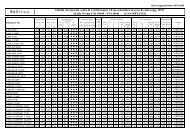
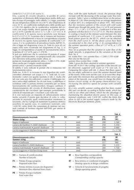
Tab. 4<br />
Dimensionamento invernale FCX NV VF PM PA RT<br />
Winter sizing (l/h) (l/h) (W)<br />
bagno • bathroom 16 1 med. 150 200 1.160<br />
camera dei bambini • child’s bedroom 21 1 min. 200 250 1.350<br />
camera matrimoniale • parent’s bedroom 31 1 min. 200 250 2.000<br />
cucina-soggiorno • kitchen-living room 31 2 med. 200 250 2 x 2.730<br />
CARATTERISTICHE • FEATURES<br />
Tab. 5<br />
Dimensionamento estivo FCX NV VF PR RF<br />
Summer sizing (l/h) (W)<br />
bagno • bathroom 16 1 med. 227 980<br />
camera bambini • child’s bedroom 21 1 min. 284 1.235<br />
camera matrimoniale • parent’s bedroom 31 1 min. 284 1.750<br />
cucina-soggiorno • kitchen-living room 31 2 med. 284 2 x 2.025<br />
NV = Numero di ventilconvettori<br />
Number of fancoils<br />
PA = Portata d’acqua proposta<br />
Proposed water flow<br />
PM = Portata minima ricavata dai diagrammi<br />
Minimum flow obtained from charts<br />
PR = Portata d’acqua risultante<br />
Final water flow<br />
RF<br />
= Resa frigorifera corrispondente<br />
Corresponding cooling capacity<br />
RT = Resa termica in condizioni di progetto<br />
Heating capacity at design conditions<br />
VF = Velocità di funzionamento di progetto<br />
Design operating speed<br />
19