aermec idrosplit - Certificazione energetica edifici
aermec idrosplit - Certificazione energetica edifici
aermec idrosplit - Certificazione energetica edifici

You also want an ePaper? Increase the reach of your titles
YUMPU automatically turns print PDFs into web optimized ePapers that Google loves.
CARATTERISTICHE • FEATURES<br />
- la caratteristica resistente del circuito alla temperatura di<br />
funzionamento invernale (per esempio 50 °C); si ricorda<br />
che tale caratteristica viene rappresentata con ottima<br />
approssimazione da una parabola di equazione:<br />
perdite di carico=k x (portata) 2 (curva 1);<br />
- la curva caratteristica della prevalenza nel funzionamento<br />
invernale a valle dell’Idrosplit (quando è in funzione la<br />
pompa della caldaia o dell’impianto di riscaldamento<br />
centralizzato); la curva (2) si costruisce sottraendo dalla<br />
prevalenza a disposizione, per ogni portata, le perdite<br />
interne dell’Idrosplit, che si leggono in tavola 7.<br />
A questo punto si può evidenziare il punto di funzionamento<br />
dell’impianto (portata - prevalenza) come punto di incrocio<br />
tra le due curve; si individua così la portata che si<br />
instaura in riscaldamento.<br />
Una volta individuata la portata d’acqua calda in circolazione,<br />
per individuare la portata di acqua refrigerata che si<br />
instaura nel periodo estivo nello stesso circuito di distribuzione<br />
(l’acqua viene spinta non più dal circolatore della caldaia<br />
ma dal circolatore dell’Idrosplit, inoltre varia la temperatura<br />
media dell’acqua e quindi le perdite per attrito), si<br />
proceda in questo modo:<br />
- nello stesso diagramma, si tracci la caratteristica resistente<br />
del circuito alla temperatura di funzionamento estivo (per<br />
esempio 10 °C); questa si ottiene moltiplicando il valore<br />
delle perdite di carico, per ogni portata, per il valore indicato<br />
in tabella 1; anche questa caratteristica viene rappresentata<br />
con ottima approssimazione da una parabola di<br />
equazione:<br />
perdite di carico=k x (portata) 2 (curva 3);<br />
- caratteristica della prevalenza a disposizione nel funzionamento<br />
estivo (quando è in funzione la pompa del<br />
modulo Idrosplit), che si può leggere nelle tavole 5 o 6<br />
(curva 4).<br />
Si può tracciare dunque il punto di funzionamento<br />
dell’impianto (portata - prevalenza) come punto di incrocio<br />
tra le due curve; si individua così la portata totale che si<br />
instaura nel funzionamento estivo. Da questa si risale alla<br />
portata di alimentazione dei singoli ventilconvettori, tenendo<br />
conto che la variazione di portata nel singolo ventilconvettore<br />
si può ritenere proporzionale alla variazione intervenuta<br />
nella portata totale.<br />
A questo punto, si deve verificare:<br />
- che la resa in raffreddamento dei singoli ventilconvettori<br />
sia sufficiente a soddisfare i carichi termici degli ambienti;<br />
tale resa è ricavabile dalle tav. 9-10-11-12 per gli FCX e<br />
tav. 17-18-19-20 per gli FCD, per le condizioni che più<br />
frequentemente si possono riscontrare in pratica; per altre<br />
condizioni di funzionamento, la resa dovrà essere ricavata<br />
dalle istruzioni a corredo dei ventilconvettori o dal<br />
programma di selezione distribuito dalla AERMEC;<br />
- che anche la portata in funzionamento estivo che alimenta<br />
ogni ventilconvettore sia superiore alla portata minima<br />
ricavabile da tab. B.<br />
Nel caso le verifiche non dovessero essere soddisfacenti, si<br />
dovranno rivedere i calcoli cambiando le grandezze di ventilconvettori,<br />
o la temperatura dell’acqua di alimentazione,<br />
od il dimensionamento del circuito idraulico.<br />
NUMERO MAX. DI VENTILCONVETTORI CONTEMPORA-<br />
NEAMENTE IN FUNZIONE NEL FUNZIONAMENTO ESTIVO<br />
Il numero massimo di ventilconvettori che possono funzionare<br />
contemporaneamente durante l’estate è variabile in<br />
dipendenza dei carichi termici istantanei associati ad ogni<br />
ventilconvettore, i quali a loro volta dipendono dalle condi-<br />
- the pattern curve of the available head in winter operation<br />
downstream to the Idrosplit (when the pump of the<br />
boiler or central heating plant is running). Curve (2) is<br />
constructed by subtracting the internal losses of the<br />
Idrosplit from the available head for each flow, which<br />
can be obtained from table 7.<br />
At this point highlight the operating point of the plant (flow -<br />
head) as the intersection between the two curves. This is<br />
how the flow attained in heating is determined.<br />
Once the hot water flow has been determined, calculate the<br />
chilled water flow attained in the summer period with the<br />
same distribution circuit (the water is no longer delivered by<br />
the boiler pump but by the Idrosplit pump, also the average<br />
water temperature changes and thus the losses due to friction).<br />
Proceed as follows:<br />
- use the same chart to trace the resistance pattern of the<br />
circuit at the temperature in summer operation (e.g.<br />
10°C). This may be obtained by multiplying the pressure<br />
drop, for each flow, by the value given in table 1. This<br />
pattern can also be represented with very close approximation<br />
by a parabola of the equation:<br />
pressure drop=k x (flow) 2 (curve 3)<br />
- pattern of the available head in summer operation (when<br />
the Idrosplit pump operates), read off table 5 or 6 (curve 4).<br />
Then the operating point of the plant can be traced (flow -<br />
head) as the point where the two curves intersect. This is<br />
how to valorise the total flow attained in summer operation.<br />
From this calculate the supply flow of the fancoils, remembering<br />
that the variation in flow of the single fancoil is proportional<br />
to the variation in the total flow.<br />
At this point, check:<br />
- that the cooling capacity of each single fancoil is sufficient<br />
to satisfy the thermal load of each room. This capacity<br />
can be obtained from tab. 9-10-11-12 for the FCX<br />
series and tab. 17-18-19-20 for the FCD series, for the<br />
conditions that are most frequently found in practice. For<br />
other operating conditions, the capacity must be obtained<br />
from the instructions provided with the fancoils or from<br />
the selection programme distributed by AERMEC.<br />
- that the flow in summer operation that supplies each fancoil<br />
is above the minimum flow given in tab. b.<br />
If these checks do not give satisfactory results, the calculations<br />
should be reviewed, changing the fancoil sizes, the<br />
supply water temperature or the sizing of the hydraulic circuit.<br />
MAX. NUMBER OF FANCOILS OPERATING SIMULTA-<br />
NEOUSLY IN SUMMER OPERATION<br />
The maximum number of fancoils that can operate simultaneously<br />
during the summer can vary depending on the thermal<br />
loads associated to each fancoil at a given time, which<br />
in their turn depend on the ambient conditions and on the<br />
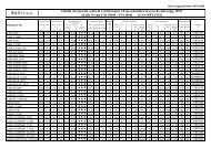
Tab. 1<br />
Temperatura acqua °C 0 10 20 30 40 50 60 70 80<br />
Water temperature<br />
Coefficiente di correzione rispetto<br />
alle perdite di carico a 50<br />
Correction factor for pressure<br />
drops at 50 °C<br />
16<br />
°C 1,36 1,28 1,17 1,10 1,05 1 0,96 0,92 0,88