aermec idrosplit - Certificazione energetica edifici
aermec idrosplit - Certificazione energetica edifici
aermec idrosplit - Certificazione energetica edifici

Create successful ePaper yourself
Turn your PDF publications into a flip-book with our unique Google optimized e-Paper software.
CARATTERISTICHE • FEATURES<br />
vettori, sempre pronti ad entrare in funzione. Naturalmente<br />
il numero di essi che possono funzionare contemporaneamente<br />
è limitato dalla potenza frigorifera a disposizione.<br />
Sarà l’utente ad escludere i ventilconvettori che riterrà<br />
opportuno, in funzione dell’occupazione dei locali. Per<br />
assicurare la massima indipendenza tra i vari locali, si consiglia<br />
l’installazione di ventilconvettori dotati di termostato<br />
ambiente incorporato.<br />
L’esclusione dal funzionamento estivo di alcuni ventilconvettori<br />
non avviene intercettando idraulicamente le singole<br />
unità, ma semplicemente tenendole spente. In queste ultime,<br />
l’acqua refrigerata circola con un incremento di temperatura<br />
minimo.<br />
Nella tubazione di ritorno dell’impianto si realizza allora la<br />
miscela di acqua a diverse temperature: più calda la portata<br />
proveniente dai ventilconvettori in funzione e praticamente<br />
alla temperatura di produzione quella proveniente dai ventilconvettori<br />
spenti. La temperatura dell’acqua all’ingresso<br />
dell’evaporatore è allora una media pesata delle varie temperature<br />
di ritorno.<br />
Ciò è consentito dal fatto che l'evaporatore a piastre del<br />
modulo ID può essere attraversato da una portata molto<br />
superiore a quella di un normale refrigeratore, a parità di<br />
potenza erogata. Grazie anche alle caratteristiche della<br />
pompa incorporata, la portata d'acqua può essere tale da<br />
assicurare un salto termico sull'evaporatore di 2,5 °C.<br />
Nel caso fosse in funzione un numero eccessivo di ventilconvettori,<br />
la potenza frigorifera assorbita da questi sarebbe<br />
maggiore della potenza messa a disposizione dal modulo<br />
ID, e pertanto si potrebbe incorrere nella situazione di non<br />
raggiungere adeguate condizioni di benessere negli ambienti<br />
serviti. Questa condizione di lavoro, peraltro non pericolosa<br />
per il buon funzionamento dell’apparecchio, viene<br />
segnalata sul pannello di controllo tramite l’accensione di<br />
una spia di sovraccarico.<br />
L’eventuale impossibilità di poter utilizzare contemporaneamente<br />
tutti i ventilconvettori installati in generale non costituisce<br />
una limitazione in quanto l’esigenza del condizionamento<br />
sopravviene in locali diversi ed in periodi diversi: per esempio<br />
in una abitazione civile possono essere individuate una zona<br />
giorno ed una zona notte da servire alternativamente.<br />
Nel funzionamento invernale, la potenzialità termica di<br />
riscaldamento deve ovviamente essere sufficiente al funzionamento<br />
contemporaneo di tutte le unità terminali installate.<br />
Nel condizionamento estivo, la potenza ridotta di Idrosplit<br />
consente di limitare l’impegno di potenza elettrica assorbita<br />
e di rientrare nei contratti normalmente stipulati con l’ENEL<br />
per le forniture ad utenze civili.<br />
Se si utilizza il modulo ID come un refrigeratore tradizionale,<br />
il numero di ventilconvettori collegabili dipende dalla potenza<br />
frigorifera che si ha a disposizione; in questo caso, tutte le<br />
unità installate possono funzionare contemporaneamente.<br />
to start operation. Naturally the number that can operate<br />
simultaneously is limited by the cooling capacity available.<br />
In this way the user can choose which fancoils he/she considers<br />
best to isolate, according to the occupation of the<br />
rooms. To ensure maximum independence between the<br />
various rooms, it is advisable to install fancoils fitted with an<br />
in-built room thermostat.<br />
The exclusion of summer operation of some fancoils is not<br />
achieved by shutting off the water supply to the single units,<br />
but by simply turning them off. In this case the chilled water<br />
circulates through them with a negligible temperature<br />
increase.<br />
The return piping of the plant is then formed a mixture of<br />
water with different temperatures: warmer for the flow<br />
coming from the fancoils in operation and practically the<br />
same as the production temperature for the water coming<br />
from the fancoils that are turned off. The water temperature<br />
at the evaporator inlet is therefore a weighted average of the<br />
various return temperatures.<br />
This is made possible by the fact that the plate evaporator in<br />
the ID module can receive a much higher flow that in a normal<br />
chiller of equal performance. Thanks also to the characteristics<br />
of the in-built pump, which enable the water flow<br />
to be sufficient to ensure a temperature differential on the<br />
evaporator of 2.5°C.<br />
In the case where there is an excessive number of fancoils<br />
in operation, absorbing a cooling capacity that would be<br />
higher than the capacity available from the ID module, this<br />
would create a situation where the locations are not reaching<br />
adequate comfort conditions. This working condition,<br />
even though it does not bear any danger whatsoever to the<br />
operation of the appliance, it is signalled on the control<br />
panel by an overload pilot light turning on.<br />
This eventual impossibility to use all the fancoils installed<br />
simultaneously, generally does not constitute a limitation<br />
since the air-conditioning requirement is usually concentrated<br />
on different rooms and at different times: for example, a<br />
house can be divided into a day area and a night area,<br />
which can be supplied alternately.<br />
In winter operation, the heating capacity must obviously be<br />
sufficient to enable all the terminal units to operate simultaneously.<br />
In summer air-conditioning, the reduced capacity of<br />
Idrosplit reduces the commitment of absorbed electric<br />
power and falls into the category of contracts usually stipulated<br />
with the Electricity Board for the supply of civil residences.<br />
If the ID module is used as a traditional chiller, the number<br />
of fancoils which can be connected depends on the cooling<br />
capacity available, but in this case, all the units installed<br />
may operate simultaneously.<br />
NUMERO DI TERMINALI COLLEGABILI • HOW MANY FANCOIL CAN BE CONNECTED<br />
Il numero di ventilconvettori collegabili in parallelo è legato<br />
alle caratteristiche del circolatore della caldaia e del gruppo<br />
ID: la portata di acqua in circolazione, dipendente dalle<br />
perdite del circuito idraulico, deve essere tale da alimentare<br />
in modo soddisfacente ogni ventilconvettore: in qualsiasi<br />
condizione di esercizio, all’interno di ogni ventilconvettore<br />
deve circolare una quantità minima di acqua.<br />
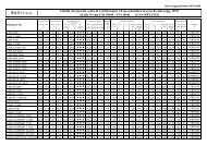
In riferimento ai ventilconvettori della serie FCX e FCD, la<br />
quantità minima, al di sotto della quale la resa termica cala<br />
drasticamente, è riportata in tab. B. Si ritiene che i ventilconvettori<br />
di taglia superiore, FCX 60, 80 e 100 non trovino<br />
applicazione in impianti che utilizzano il modulo ID. Per<br />
essi, infatti, il limite inferiore di portata sarebbe di 400 l/h. La<br />
determinazione del numero di ventilconvettori collegabili è<br />
quindi legata alla portata totale di acqua in gioco, la quale è<br />
la somma di quelle necessarie ai singoli ventilconvettori per<br />
soddisfare il carico termico relativo a ciascuno di essi.<br />
The number of fancoils that can be connected in parallel is<br />
tied to the characteristics of the boiler pump and ID unit:<br />
the water flow, which depends on the pressure drops of the<br />
hydraulic circuit, must be enough to adequately supply<br />
each fancoil. In any working condition, each fancoil must<br />
receive a minimum flow of water. With reference to the<br />
FCX and FCD series of fancoils, the minimum quantity,<br />
below which performance falls drastically, is given in tab.<br />
B. In this analysis the larger fancoils, FCX 60, 80 and 100<br />
cannot be applied to plants involving an ID module. In<br />
fact, their lowest flow limit would be 400 l/h. Determination<br />
of how many fancoils can be connected is thus tied to the<br />
total water flow in play, which is the sum of the flows needed<br />
by each single fancoil to satisfy its specific thermal<br />
load.<br />
14