aermec idrosplit - Certificazione energetica edifici
aermec idrosplit - Certificazione energetica edifici
aermec idrosplit - Certificazione energetica edifici

Create successful ePaper yourself
Turn your PDF publications into a flip-book with our unique Google optimized e-Paper software.
L’ALIMENTAZIONE CON ACQUA CALDA • SUPPLY OF HOT WATER<br />
Il modulo Idrosplit può essere alimentato con una portata di<br />
acqua calda di qualsiasi provenienza; in ogni caso, per<br />
garantire un buon funzionamento del sistema è opportuno<br />
controllare le caratteristiche della pompa di circolazione<br />
dell’acqua calda, che deve assicurare la giusta portata<br />
d’acqua alle singole utenze. Infatti, l’acqua calda, prima di<br />
essere distribuita alle utenze, entra nel modulo ID, dove<br />
incontra una resistenza proporzionale alla portata secondo<br />
quanto illustrato nella tav. 7.<br />
CRITERI DI SCELTA • SELECTION<br />
Le curve di tav. 1 e 2 riportano, per il modulo ID 31 abbinato,<br />
rispettivamente, al CWX 166 e al CX 166, la resa frigorifera<br />
e la potenza assorbita totale al variare della temperatura<br />
dell’acqua prodotta.<br />
Le curve di tav. 3 e 4 riportano, per il modulo ID 51 abbinato,<br />
rispettivamente, al CWX 266 e al CX 266, la resa frigorifera<br />
e la potenza elettrica assorbita totale (per i modelli<br />
monofase) al variare della temperatura dell’aria esterna e<br />
della temperatura dell’acqua prodotta. Per il modello trifase<br />
la potenza assorbita si ricava dai rispettivi assorbimenti del<br />
modello monofase, sottraendo 50 W, fermo restando la<br />
potenza frigorifera prodotta. I valori indicati da tali diagrammi<br />
sono riferiti ad un salto termico costante sull’acqua, di 5<br />
°C. Per salti termici diversi, moltiplicare la resa frigorifera<br />
per i valori della tabella riportata di seguito.<br />
Salto termico acqua refrigerata °C 3 5 8 10<br />
Fattore correttivo Pot. frigorifera 0,99 1 1,02 1,03<br />
La potenza assorbita non è influenzata apprezzabilmente<br />
dal salto termico dell’acqua.<br />
Le curve di tav. 5 e 6 forniscono le prevalenze utili a disposizione<br />
per l’impianto di distribuzione dell’acqua refrigerata,<br />
rispettivamente per il modulo ID 31 ed ID 51.<br />
La tav. 7 fornisce le perdite di carico interne dei moduli ID<br />
31 ed ID 51 alle varie portate. Conoscendo la caratteristica<br />
del circolatore dell’eventuale caldaia o, in ogni caso, la prevalenza<br />
a disposizione a monte di Idrosplit, si può così risalire<br />
alla prevalenza utile disponibile per l’impianto di distribuzione.<br />
Le curve di tav. 8 riportano il consumo di acqua<br />
delle motocondensanti CWX al variare della temperatura<br />
dell’acqua di alimentazione.<br />
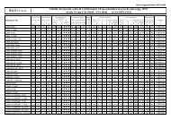
Le tav. da 9 a 16 forniscono i valori di resa frigorifera e termica<br />
dei ventilconvettori della serie FCX al variare della portata<br />
d'acqua. Le tav. da 17 a 24 forniscono, invece, i valori<br />
per la serie FCD. Le temperature dell'aria e dell'acqua in<br />
ingresso sono quelle che maggiormente si riscontrano nella<br />
pratica (differenza di temperatura tra acqua ed aria entrante<br />
pari a 50-40-30 °C in riscaldamento; 7-8-9 °C per l'acqua,<br />
27 °C B.S. e 19 °C B.U. per l'aria in raffreddamento).<br />
Le tabelle A, B ed E riportano le portate d'aria dei ventilconvettori<br />
della serie FCX e FCD alle varie velocità, le perdite di carico<br />
lato acqua al variare della portata con temperatura media<br />
dell'acqua di 10 °C, i dati di rumorosità delle motocondensanti<br />
CX. Le motocondensanti ad aria della serie CX sono progettate<br />
per funzionare correttamente fino ad una temperatura esterna<br />
minima di 20 °C. Qualora sia previsto il funzionamento del<br />
modulo ID con temperature esterne minori di questa temperatura,<br />
sarà necessario prevedere l’inserimento del dispositivo di<br />
controllo della pressione di condensazione DCPX.<br />
The Idrosplit module can use hot water from any form of<br />
supply. In any case to guarantee a proper operation of the<br />
system it is good practice to control the hot water pump<br />
characteristics, which must ensure the correct water flow to<br />
each single terminal. In fact, before the hot water is distributed<br />
to the terminals, it enters the ID module, where it meets<br />
a resistance proportional to the flow, according to the data<br />
given in tab.7.<br />
The charts in tab. 1 and 2 give data regarding the ID 31<br />
module combined to the CWX and the CX 266 respectively,<br />
including the cooling capacity and total absorbed power<br />
against the change in ambient temperature and chilled<br />
water temperature<br />
The charts in tab.1 and 2 give data regarding the ID 51<br />
module combined to the CWX and the CX 266 respectively,<br />
including cooling capacity and total absorbed power (single<br />
phase version) against the change in ambient temperature<br />
and chilled water temperature. For the three phase model<br />
the absorbed power can be obtained by subtracting 50W<br />
from the respective absorptions of the single phase model,<br />
with the cooling capacity produced remaining the same.<br />
The values given in these charts are referred to a constant<br />
water temperature differential of 5°C. For other temperature<br />
differentials, multiply the cooling capacity by the coefficients<br />
given in the table below.<br />
Chilled water temp. differential °C 3 5 8 10<br />
Cooling capacity correction factor 0,99 1 1,02 1,03<br />
The water temperature differential has a negligible influence<br />
on absorbed power.<br />
The charts in tab. 5 and 6 provide the available heads for<br />
the chilled water distribution plant, for the ID 31 and ID 51<br />
modules respectively.<br />
Tab. 7 provides the internal pressure drops of ID 31 and ID<br />
51 at the various flows. If the pump characteristics of the<br />
eventual boiler are known, or in any case, the available<br />
head upstream to the Idrosplit, the available head for the<br />
distribution plant can be obtained. The charts in tab. 8 give<br />
the water consumption of the CWX condensing unit against<br />
various supply water temperatures.<br />
Tab. 9 to 16 provide the cooling and heating capacities of<br />
the fancoils of the FCX series against variations in the water<br />
flow. Tab. 17 to 24 provide the values for the FCD series.<br />
The air and water inlet temperatures are those more commonly<br />
found in practice (temperature difference between<br />
water and inlet air equal to 50-40-30 °C in heating; 7-8-9<br />
°C for the water, 27°C D.B. and 19°C W.B. for the air in<br />
cooling).<br />
Tables A, B, and E state the air flows for fancoils of the FCX<br />
and FCD series at the various speeds, the water pressure<br />
drops against variations in flow with an average water temperature<br />
of 10°C, and the noise level data for the CX condensing<br />
units. The CX series condensing units are designed<br />
to operate correctly with a minimum ambient temperature<br />
of 20°C. If operation of the ID module should be considered<br />
at lower ambient temperatures the DCPX condensing pressure<br />
control must be provided.<br />
CARATTERISTICHE • FEATURES<br />
CONSIDERAZIONI IMPIANTISTICHE • PLANT CONSIDERATIONS<br />
Caratteristica peculiare del modulo ID è di poter alimentare,<br />
con una portata d’acqua a temperatura prefissata, un numero<br />
di ventilconvettori la cui resa frigorifera totale sarebbe<br />
superiore alla potenza frigorifera erogata dal modulo.<br />
Si può così realizzare un impianto che distribuisca acqua<br />
refrigerata ad un numero relativamente grande di ventilcon-<br />
An interesting feature of the ID module is the possibility to<br />
supply, with a pre-set water flow and temperature, a number<br />
of fancoils whose total cooling capacity would normally<br />
exceed the cooling capacity supplied by the module.<br />
In this way a plant can be designed to distribute chilled<br />
water to a relatively large number of fancoils, always ready<br />
13