Snodi sferici radiali - Sea
Snodi sferici radiali - Sea
Snodi sferici radiali - Sea

You also want an ePaper? Increase the reach of your titles
YUMPU automatically turns print PDFs into web optimized ePapers that Google loves.
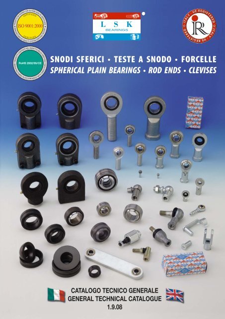
SNODI SFERICI • TESTE A SNODO • FORCELLE<br />
SPHERICAL PLAIN BEARINGS • ROD ENDS • CLEVISES<br />
CATALOGO TECNICO GENERALE<br />
GENERAL TECHNICAL CATALOGUE<br />
1.9.08
Su richiesta, sono fornibili prodotti con misure in pollici. Under request, are available products in inches sizes.<br />
Su richiesta, sono fornibili prodotti a disegno. Under request, we can supply products as per specific drawing.<br />
Su richiesta, tutti i prodotti LSK® sono<br />
fornibili in acciaio inox.<br />
Under request, all LSK® products<br />
in<br />
stainless steel.<br />
are available<br />
Politica ambientale<br />
Tecnico LSK ® stato<br />
ecologico riciclato al 100%.<br />
ISO 14001 e ISO 9001:2000.<br />
Environmental policy<br />
This Technical Catalogue LSK ® has been produced with 100% ecological recycled paper.<br />
Manufacturing process follows the regulations in force: DS/EN ISO 14001 and ISO 9001:2000.<br />
Inks used are vegetable based. Please continue your actions in order to protect the environment and recycle properly.<br />
Catalogo materiale<br />
DS/EN<br />
con Il processo produttivo della carta avviene attenendosi alle vigenti normative: Gli inchiostri utilizzati per la stampa, sono a base vegetale. Per cortesia, continuate nel Vostro impegno costante per la salvaguardia dellÕambiente<br />
realizzato presente
SEDE PRINCIPALE<br />
HEAD OFFICE<br />
MAGAZZINO<br />
WAREHOUSE<br />
UFFICIO COMMERCIALE<br />
SALES DEPARTMENT<br />
ITALCUSCINETTI<br />
forniture industriali<br />
industrial supplies<br />
S.p.A.<br />
Italcuscinetti S.p.A. - Via Caponnetto, 15 - 42048 RUBIERA (Reggio Emilia) Italia<br />
Vendite Italia Tel. 00390522621811 - Fax 00390522628926 - E-mail: comm.it@italcuscinetti.it<br />
Export sales dept. Tel. 00390522621830 - Fax 00390522626149 - E-mail: export@italcuscinetti.it<br />
Import dept. Tel. 00390522621880 - Fax 00390522629255 - E-mail: import@italcuscinetti.it<br />
info@italcuscinetti.it - www.italcuscinetti.it<br />
IMPORTATORE - DISTRIBUTORE ESCLUSIVISTA PER L’EUROPA* IMPORTER - DISTRIBUTOR EUROPEAN SOLE AGENT*<br />
® SKF<br />
NBS<br />
FAG<br />
CUSCINETTI<br />
BEARINGS *<br />
CUSCINETTI CUSCINETTI A RULLINI<br />
PER APPLICAZIONI NEEDLE BEARINGS *<br />
“BASSA RUMOROSITÀ”<br />
BEARINGS FOR *<br />
“LOW NOISE” APPLICATIONS<br />
COMPONENTI PER LA<br />
MOVIMENTAZIONE LINEARE<br />
COMPONENTS FOR *<br />
LINEAR MOTION<br />
RUOTE LIBERE<br />
FREE WHEELS *<br />
SUPPORTI<br />
AUTOALLINEANTI<br />
SELF-ALIGNING *<br />
BEARING UNITS<br />
SUPPORTI<br />
AUTOALLINEANTI<br />
SELF-ALIGNING *<br />
BEARING UNITS<br />
TESTE A SNODO<br />
SNODI SFERICI<br />
ROD ENDS *<br />
SPHERICAL PLAIN<br />
BEARINGS<br />
BOCCOLE<br />
BUSHES *<br />
CATENE<br />
CHAINS *<br />
CATENE<br />
CHAINS<br />
CUSCINETTI<br />
BEARINGS<br />
CUSCINETTI<br />
BEARINGS
Programma generale di vendita<br />
General sales program<br />
CUSCINETTI *<br />
BEARINGS *<br />
SUPPORTI AUTOALLINEANTI<br />
SELF-ALIGNING BEARING UNITS<br />
CUSCINETTI PER APPLICAZIONI “BASSA RUMOROSITÀ” *<br />
BEARINGS FOR “LOW NOISE” APPLICATIONS *<br />
SNODI SFERICI - TESTE A SNODO - FORCELLE *<br />
SPHERICAL PLAIN BEARINGS - ROD ENDS - CLEVISES *<br />
CUSCINETTI A RULLINI *<br />
NEEDLE BEARINGS *<br />
BOCCOLE *<br />
BUSHES *<br />
COMPONENTI PER LA MOVIMENTAZIONE LINEARE *<br />
COMPONENTS FOR LINEAR MOTION *<br />
CATENE *<br />
CHAINS *<br />
Disponibile grande assortimento completo<br />
con pronta consegna.<br />
Big and full assortment with prompt<br />
delivery.<br />
SUPPORTI AUTOALLINEANTI *<br />
SELF-ALIGNING BEARING UNITS *<br />
CUSCINETTI SKF - FAG<br />
SKF - FAG BEARINGS<br />
* Per ulteriori informazioni, potete richiedere il Catalogo Tecnico * For further information, please ask for the Technical Catalogue
Indice generale catalogo<br />
General catalogue index<br />
- Indice generale dei prodotti - General products index pag. II<br />
1. Introduzione 1. Introduction pag. 1<br />
2. Dimensioni, tolleranze e precisioni 2. Dimensions, tollerances and precisions pag. 1<br />
3. Giuoco del cuscinetto 3. Clearance of the bearing pag. 2<br />
4. Fissaggio radiale dei cuscinetti (accoppiamenti) 4. Radial fixing of the bearings (coupling) pag. 4<br />
5. Lavorazione ed esecuzione dell’alloggiamento 5. Working and execution of the housing pag. 5<br />
6. Qualità dell’albero e del foro dall’alloggiamento 6. Quality of the shaft and the housing opening pag. 6<br />
7. Condizioni d’accoppiamento 7. Coupling conditions pag. 6<br />
8. Fissaggio assiale dei cuscinetti 8. Axial fixtures of the bearings pag. 7<br />
9. Utilizzo (montaggio e smontaggio) 9. Use (mounting and dismounting) pag. 8<br />
10. Protezione della sede 10. Protection of the seat pag. 9<br />
11. Lubrificazione 11. Lubrication pag. 10<br />
12. Attrito 12. Friction pag. 11<br />
13. Temperatura 13. Temperature pag. 12<br />
14. Carico 14. Load pag. 13<br />
15. Carico dinamico C 15. Dynamic load C pag. 14<br />
16. Carico statico C 0<br />
16. Static load C 0<br />
pag. 14<br />
17. Movimenti degli snodi <strong>sferici</strong> 17. Movements of the spherical plain bearings pag. 15<br />
18. <strong>Snodi</strong> <strong>sferici</strong> richiedenti manutenzione 18. Maintenance spherical plain bearings pag. 16<br />
19. <strong>Snodi</strong> <strong>sferici</strong> <strong>radiali</strong> (richiedenti manutenzione) 19. Radial spherical plain bearings (requiring maintenance) pag. 16<br />
20. <strong>Snodi</strong> <strong>sferici</strong> assiali (richiedenti manutenzione) 20. Axial spherical plain bearings (requiring maintenance) pag. 17<br />
21. <strong>Snodi</strong> <strong>sferici</strong> a contatto obliquo (richiedenti manutenzione) 21. Angular contact spherical plain bearings (requiring maintenance) pag. 17<br />
22. Durata 22. Life pag. 18<br />
23. <strong>Snodi</strong> <strong>sferici</strong> non richiedenti manutenzione 23. Maintenance-free spherical plain bearings pag. 22<br />
24. <strong>Snodi</strong> <strong>sferici</strong> <strong>radiali</strong> (non richiedenti manutenzione) 24. Radial spherical plain bearings (maintenance-free) pag. 22<br />
25. <strong>Snodi</strong> <strong>sferici</strong> assiali (non richiedenti manutenzione) 25. Axial spherical plain bearings (maintenance-free) pag. 23<br />
26. <strong>Snodi</strong> <strong>sferici</strong> a contatto obliquo (non richiedenti manutenzione) 26. Angular contact spherical plain bearings (maintenance-free) pag. 23<br />
27. Durata 27. Life pag. 24<br />
28. Teste a snodo 28. Rod ends pag. 28<br />
29. Teste a snodo SI - SA 29. SI - SA rod ends pag. 28<br />
30. Teste a snodo TSF - TSM 30. TSF -TSM rod ends pag. 28<br />
31. Teste a snodo per idraulica TAPR.N - TAPR.U - TAPR.DO - TAPR.CE 31. Rod ends for hydraulic TAPR.N - TAPR.U - TAPR.DO - TAPR.CE pag. 29<br />
32. Teste a snodo per idraulica con fusione saldabile T.A.C. - T.P.N. 32. Rod ends for hydraulic with weld able housing T.A.C. - T.P.N. pag. 29<br />
33. Manutenzione e lubrificazione 33. Maintenance and lubrication pag. 30<br />
34. Carico dinamico C delle teste a snodo 34. Rod ends dynamic load C pag. 30<br />
35. Carico statico C 0<br />
delle teste a snodo 35. Rod ends static load C 0<br />
pag. 30<br />
36. Carico ammissibile sulla testa a snodo 36. Allowed load on rod ends pag. 31<br />
37. Criteri di rottura 37. Breaking causes pag. 32<br />
38. Forcelle con foro e gambo filettato ed accessori di complemento 38. Clevises with threaded hole and pins with complementary accessories pag. 33<br />
TABELLE DIMENSIONALI DIMENSIONAL TABLES<br />
<strong>Snodi</strong> <strong>sferici</strong> Spherical plain bearings pag. 37<br />
Terminali ed articolazioni - Teste a snodo Ball joint rod ends - Rod ends pag. 59<br />
Forcelle ed accessori di complemento Clevises and complementary accessories pag. 81<br />
SIMBOLI E TOLLERANZE SYMBOLS AND TOLERANCES pag. 93<br />
Tolleranze per snodi <strong>sferici</strong> <strong>radiali</strong> Tolerances for radial spherical plain bearings pag. 94<br />
Tolleranze per snodi <strong>sferici</strong> assiali (GX..S - GX..CP - GX..SP) Tolerances for spherical plain thrust bearings (GX..S - GX..CP - GX..SP) pag. 96<br />
Tolleranze per snodi <strong>sferici</strong> a contatto obliquo (GAC..S - GAC..CP - GAC..SP) Tolerance for angular contact spherical plain bearings (GAC..S - GAC..CP - GAC..SP) pag. 97<br />
Tolleranze teste a snodo Tolerances for rod ends pag. 98<br />
39. Tabella d’intercambiabilità 39. Interchangeability table pag. 99<br />
40. Scheda informativa 40. Informative card pag. 100<br />
I
Indice generale dei prodotti<br />
General products index<br />
Pagina<br />
Page<br />
Sigla<br />
Designation<br />
GE..E/ES<br />
Tipo<br />
Type<br />
Dimensioni (diametro interno)<br />
Dimensions (inner diameter)<br />
mm.<br />
Accoppiamento di strisciamento<br />
Sliding coupling<br />
37<br />
<strong>Snodi</strong> <strong>sferici</strong> <strong>radiali</strong> anche<br />
scanalati, senza tenute<br />
Spherical plain radial<br />
bearings, without seals<br />
4 - 1.000<br />
acciaio/acciaio<br />
steel/steel<br />
GE..ES 2RS<br />
37<br />
<strong>Snodi</strong> <strong>sferici</strong> <strong>radiali</strong> anche<br />
scanalati, con tenute<br />
Spherical plain radial<br />
bearings, with seals<br />
15 - 300<br />
acciaio/acciaio<br />
steel/steel<br />
GEG..E/ES<br />
39<br />
<strong>Snodi</strong> <strong>sferici</strong> <strong>radiali</strong> anche<br />
scanalati, senza tenute<br />
Spherical plain radial<br />
bearings, without seals<br />
4 - 280<br />
acciaio/acciaio<br />
steel/steel<br />
GEG..ES 2RS<br />
39<br />
<strong>Snodi</strong> <strong>sferici</strong> <strong>radiali</strong> anche<br />
scanalati, con tenute<br />
Spherical plain radial<br />
bearings, with seals<br />
15 - 280<br />
acciaio/acciaio<br />
steel/steel<br />
GE..SB<br />
40<br />
<strong>Snodi</strong> <strong>sferici</strong> <strong>radiali</strong> anche<br />
scanalati, senza tenute<br />
Spherical plain radial<br />
bearings, without seals<br />
5 - 30<br />
acciaio/bronzo<br />
steel/bronze<br />
GE..SP<br />
41<br />
<strong>Snodi</strong> <strong>sferici</strong> <strong>radiali</strong>,<br />
senza tenute<br />
Spherical plain radial<br />
bearings, without seals<br />
5 - 30<br />
acciaio/PTFE<br />
steel/PTFE<br />
GE..CP<br />
42<br />
<strong>Snodi</strong> <strong>sferici</strong> <strong>radiali</strong><br />
(serie pesante)<br />
Spherical plain radial<br />
bearings, (heavy duty)<br />
100 - 630<br />
Cromo duro/PTFE<br />
Hard chromium/PTFE<br />
43<br />
GEEW..ES<br />
<strong>Snodi</strong> <strong>sferici</strong> <strong>radiali</strong><br />
scanalati con anello<br />
interno largo,<br />
senza tenute<br />
Spherical plain radial<br />
bearings with wide inner<br />
ring, without seals<br />
12 - 320<br />
acciaio/acciaio<br />
steel/steel<br />
GEEM..ES 2RS<br />
44<br />
<strong>Snodi</strong> <strong>sferici</strong> <strong>radiali</strong><br />
scanalati con anello<br />
interno largo, con tenute<br />
Spherical plain radial<br />
bearings with wide inner<br />
ring and seals<br />
17 - 80<br />
acciaio/acciaio<br />
steel/steel<br />
45<br />
GE..C<br />
<strong>Snodi</strong> <strong>sferici</strong> <strong>radiali</strong> esenti<br />
da manutenzione, senza<br />
tenute<br />
Maintenance-free<br />
spherical plain radial<br />
bearings, without seals<br />
4 - 30<br />
Cromo duro/PTFE<br />
Hard chromium/PTFE<br />
II
Indice generale dei prodotti<br />
General products index<br />
Lubrificazione<br />
Lubrication<br />
Si<br />
Yes<br />
Si<br />
Yes<br />
Temperatura °C<br />
Temperature °C<br />
-60 ~ +200<br />
-60 ~ +130<br />
Caratteristiche tecniche e principali campi d’applicazione<br />
Technical details and main application fields<br />
Anello esterno ed anello interno temprati, con scanalatura sull’anello esterno e foro di lubrificazione, esecuzione<br />
senza e con tenute. Particolarmente indicati per condizioni di funzionamento con elevati carichi alternati e carichi<br />
d’urto; applicazioni indicate per macchine da costruzione, cilindri idraulici, nel settore automezzi da trasporto<br />
stradale e navale.<br />
Hardened outer and inner ring, with groove on outer ring and lubrication hole, with or without seals. Particularly suitable<br />
for working with high alternate loads and impact loads; suitable for building machinery, hydraulic cylinders, vehicles for<br />
road and naval transport.<br />
Si<br />
Yes<br />
-60 ~ +200<br />
L’anello interno maggiorato, consente un maggior angolo di ribaltamento . Le caratteristiche tecniche ed i principali<br />
campi d’applicazione sono da intendersi equivalenti al tipo GE.<br />
The oversize inner ring allows a wider turnover angle . Technical characteristics and main applications are the same<br />
as for GE type.<br />
Si<br />
Yes<br />
-60 ~ +130<br />
Si<br />
Yes<br />
-60 ~ +250<br />
Anello esterno sagomato sull’anello interno. Particolarmente indicati per utilizzo su macchine per imballaggio,<br />
macchine da stampa, macchine da trasporto e selezionatura.<br />
Outer ring shaped on inner ring. Particularly suitable for packing machinery, printing machinery, conveyor and sorting<br />
machinery.<br />
No -50 ~ +200<br />
Anello esterno sagomato sull’anello interno. Particolarmente indicati per utilizzo su macchine per imballaggio,<br />
macchine da stampa, apparecchi per il sollevamento.<br />
Outer ring shaped on inner ring. Particularly suitable for packing machinery, printing machinery, lifting devices.<br />
No -50 ~ +130<br />
Anello interno temprato, anello esterno non temprato, tagliato radialmente e trattenuto con viti di bloccaggio.<br />
Particolarmente indicati per la costruzione di macchine pesanti, attrezzature di sollevamento, gru, carri ponte.<br />
Hardened inner ring, outer ring not hardened, radial cut and tightened with a blocking screws. Particularly suitable for<br />
building heavy vehicles, lifting equipments, cranes, bridge cranes.<br />
Si<br />
Yes<br />
-60 ~ +200<br />
Anello interno ed esterno temprati. Sull’anello esterno è presente una spaccatura assiale per il montaggio dell’anello<br />
interno. Costruiti secondo DIN 24338, particolarmente indicati per l’attacco di pistoni e cilindri normalizzati.<br />
Hardened inner and outer ring. The outer ring has an axial rift for inner ring mounting. Manufactured according to DIN<br />
24338, and particularly suitable for coupling pistons and standardized cylinders.<br />
Si<br />
Yes<br />
-60 ~ +130<br />
No -50 ~ +200<br />
Le caratteristiche tecniche ed i principali campi d’applicazione sono da intendersi equivalenti al tipo GE. Si<br />
differenziano tuttavia per particolari prolungamenti cilindrici sull’anello interno, che ne consente il montaggio<br />
evitando l’applicazione di anelli distanziatori, tra gli spallamenti.<br />
Main technical characteristics and application fields are equivalent to the GE type. However, they are different for the<br />
presence of special cylindrical extensions on the inner ring, which allow the assembling without using spacer rings<br />
between shoulders.<br />
Anello interno temprato, anello esterno costituito da una parte esterna in acciaio ed una parte interna con tessuto<br />
PTFE che scorre sull’anello interno. In condizioni normali di funzionamento sono particolarmente indicati per stantuffi<br />
di cilindri idraulici, attrezzature in generale da sollevamento.<br />
Hardened inner ring, outer ring formed by an external steel part and an internal PTFE part. In normal working conditions<br />
they are particularly suitable for hydraulic cylinders pistons of and lifting equipment.<br />
III
Indice generale dei prodotti<br />
General products index<br />
Pagina<br />
Page<br />
Sigla<br />
Designation<br />
GE..ET 2RS<br />
Tipo<br />
Type<br />
Dimensioni (diametro interno)<br />
Dimensions (inner diameter)<br />
mm.<br />
Accoppiamento di strisciamento<br />
Sliding coupling<br />
45<br />
<strong>Snodi</strong> <strong>sferici</strong> <strong>radiali</strong> esenti<br />
da manutenzione, con<br />
tenute<br />
Maintenance-free<br />
spherical plain radial<br />
bearings, with seals<br />
17 - 300<br />
Cromo duro/PTFE<br />
Hard chromium/PTFE<br />
46<br />
GEG..C<br />
<strong>Snodi</strong> <strong>sferici</strong> <strong>radiali</strong> esenti<br />
da manutenzione, senza<br />
tenute<br />
Maintenance-free<br />
spherical plain radial<br />
bearings, without seals<br />
4 - 30<br />
Cromo duro/PTFE<br />
Hard chromium/PTFE<br />
46<br />
GEG..ET 2RS<br />
<strong>Snodi</strong> <strong>sferici</strong> <strong>radiali</strong> esenti<br />
da manutenzione, con<br />
tenute<br />
Maintenance-free<br />
spherical plain radial<br />
bearings, with seals<br />
30 - 280<br />
Cromo duro/PTFE<br />
Hard chromium/PTFE<br />
GAC..S<br />
47<br />
<strong>Snodi</strong> <strong>sferici</strong> a contatto<br />
obliquo<br />
Angular contact spherical<br />
plain bearings<br />
25 - 200<br />
acciaio/acciaio<br />
steel/steel<br />
GAC..CP<br />
48<br />
<strong>Snodi</strong> <strong>sferici</strong> a contatto<br />
obliquo<br />
Angular contact spherical<br />
plain bearings<br />
25 - 200<br />
Cromo duro/PTFE<br />
Hard chromium/PTFE<br />
GAC..SP<br />
49<br />
<strong>Snodi</strong> <strong>sferici</strong> a contatto<br />
obliquo<br />
Angular contact spherical<br />
plain bearings<br />
25 - 200<br />
acciaio/PTFE<br />
steel/PTFE<br />
GX..S<br />
50<br />
<strong>Snodi</strong> <strong>sferici</strong><br />
assiali<br />
Spherical plain thrust<br />
bearings<br />
10 - 200<br />
acciaio/acciaio<br />
steel/steel<br />
GX..CP<br />
51<br />
<strong>Snodi</strong> <strong>sferici</strong><br />
assiali<br />
Spherical plain thrust<br />
bearings<br />
10 - 360<br />
Cromo duro/PTFE<br />
Hard chromium/PTFE<br />
GX..SP<br />
52<br />
<strong>Snodi</strong> <strong>sferici</strong><br />
assiali<br />
Spherical plain thrust<br />
bearings<br />
10 - 200<br />
acciaio/PTFE<br />
steel/PTFE<br />
IV
Indice generale dei prodotti<br />
General products index<br />
Lubrificazione<br />
Lubrication<br />
Temperatura °C<br />
Temperature °C<br />
Caratteristiche tecniche e principali campi d’applicazione<br />
Technical details and main application fields<br />
No -50 ~ +130<br />
No -50 ~ +200<br />
Anello interno ed esterno temprati. Sull’anello esterno è presente una spaccatura assiale per il montaggio (fino<br />
a diametro 120 mm.); per diametri superiori, l’anello esterno è diviso assialmente e trattenuto da anelli. Le<br />
caratteristiche tecniche ed i principali campi d’applicazione sono da intendersi equivalenti al tipo GE..C, ma con<br />
prestazioni superiori.<br />
Hardened inner and outer ring. An axial rift for assemblying is present on the outer ring (up to diameter 120 mm.); for<br />
bigger diameters the external ring is splitted and blocked by rings. The technical characteristics and application fields are<br />
equivalent to the GE..C type, but with better performances.<br />
Le caratteristiche tecniche ed i principali campi d’applicazione sono da intendersi equivalenti al tipo GE..C. Si<br />
differenziano tuttavia per l’anello interno maggiorato, che consente un maggior angolo di ribaltamento .<br />
The main technical characteristics and application fields are equivalent to the GE C. type. However, they are different for<br />
the bigger inner ring, which allows a wider turnover angle .<br />
No -50 ~ +130<br />
Le caratteristiche tecniche ed i principali campi d’applicazione sono da intendersi equivalenti al tipo GE..ET 2RS. Si<br />
differenziano tuttavia per l’anello interno maggiorato, che consente un maggior angolo di ribaltamento .<br />
The main technical characteristics and application fields are equivalent to the GE..ET 2RS type. However, they are different<br />
for the bigger inner ring, which allows a wider turnover angle .<br />
Si<br />
Yes<br />
-60 ~ +200<br />
No -50 ~ +150<br />
Anello interno ed esterno completamente separabili ed entrambi temprati; possono essere considerati l’alternativa ai<br />
cuscinetti a rulli conici. Presentano scanalatura e foro di lubrificazione sull’anello esterno. Grazie alla loro forma, sono<br />
adatti in caso di carichi dinamici mutevoli e qualora i carichi d’urto, uniti a piccoli angoli d’oscillazione producessero<br />
danni. Particolarmente indicati per supporti a cerniera elastica, assali di rimorchi, in generale nel settore dei<br />
trasporti.<br />
Inner and outer ring are both hardened and completely separable; they can be considered as an alternative to taper roller<br />
bearing. They have grooves and lubrication hole on the outer ring. Due to their shape they are suitable in case of dynamic<br />
loads or when impact loads, together with little oscillation angles, should cause damages. They are particularly suitable<br />
for elastic inge support, trailers’ axle and general in the transport field.<br />
Le caratteristiche tecniche ed i principali campi d’applicazione sono da intendersi equivalenti al tipo GAC.S.<br />
Particolarmente indicati in presenza di movimenti minimi, ma con forti carichi.<br />
The technical characteristics and applications fields are equivalent to GAC..S. type. Particularly suitable in case of<br />
minimum movements and heavy loads.<br />
No -40 ~ +150<br />
Le caratteristiche tecniche ed i principali campi d’applicazione sono da intendersi equivalenti al tipo GAC..S e GAC..CP.<br />
Se utilizzati in coppia, possono sopportare carichi assiali in entrambi i sensi.<br />
The technical characteristics and application fields can be considered equivalent to the GAC...S and GAC...CP types. When<br />
used paired, they can bear axial loads in both directions.<br />
Si<br />
Yes<br />
-60 ~ +200<br />
No -50 ~ +150<br />
No -40 ~ +150<br />
Ralla dell’albero e dell’alloggiamento temprate ed entrambe separabili l’una dall’altra; possono essere combinati<br />
direttamente con snodi <strong>sferici</strong> <strong>radiali</strong>. Presentano scanalatura e foro di lubrificazione sulla ralla d’alloggiamento.<br />
Rappresentano una valida alternativa ai cuscinetti a rulli conici della serie 320..; adatti a sopportare forze assiali e<br />
<strong>radiali</strong>, nei movimenti di regolazione sono soggetti a carico unidirezionale.<br />
Shaft and housing fifth wheel both hardened and separable, they can be joined directly with spherical radial bearings.<br />
They have groove and lubrication hole on the fifth wheel. They represent an alternative for taper roller bearing of the<br />
series 320..; they can bear axial and radial loads, in the adjustment movement are subject only to unidirectional load.<br />
Le caratteristiche tecniche ed i principali campi d’applicazione sono da intendersi equivalenti al tipo GX..S.<br />
Particolarmente indicati in presenza di movimenti minimi, ma con forti carichi. La ralla per alloggiamento a partire<br />
dal diametro 160 mm. non è temprata<br />
The technical characteristics and applications fields are equivalent to the GAC..S type. They are particularly suitable in<br />
case of minimum movements and heavy loads. The fifth wheel starting from diameter 160 mm is not hardened.<br />
Le caratteristiche tecniche ed i principali campi d’applicazione sono da intendersi equivalenti al tipo GX..S e GX..CP. In<br />
caso siano combinati con snodi <strong>radiali</strong>, possono sopportare carichi <strong>radiali</strong> ed assiali in entrambi i sensi.<br />
The technical characteristics and the main application fields are equivalent to the GX..S e GX..CP types. In case they are<br />
combined with plain radial bearings, they can bear radial and axial loads in both directions.<br />
V
Indice generale dei prodotti<br />
General products index<br />
Pagina<br />
Page<br />
Sigla<br />
Designation<br />
GEZ..ES<br />
Tipo<br />
Type<br />
Dimensioni (diametro interno)<br />
Dimensions (inner diameter)<br />
mm.<br />
Accoppiamento di strisciamento<br />
Sliding coupling<br />
53<br />
<strong>Snodi</strong> <strong>sferici</strong> <strong>radiali</strong><br />
scanalati, senza tenute<br />
(misure in pollici)<br />
Spherical plain radial<br />
bearings, without seals<br />
(inches sizes)<br />
12,7 - 152,4<br />
acciaio/acciaio<br />
steel/steel<br />
GEZ..ES 2RS<br />
53<br />
<strong>Snodi</strong> <strong>sferici</strong> <strong>radiali</strong><br />
scanalati, con tenute<br />
(misure in pollici)<br />
Spherical plain radial<br />
bearings, with seals<br />
(inches sizes)<br />
25,4 - 152,4<br />
acciaio/acciaio<br />
steel/steel<br />
GE..XS K<br />
54<br />
<strong>Snodi</strong> <strong>sferici</strong> <strong>radiali</strong><br />
in due pezzi<br />
Spherical plain radial<br />
bearings with two-pieces<br />
12 - 150<br />
acciaio/acciaio<br />
steel/steel<br />
GEK..XS 2RS<br />
55<br />
<strong>Snodi</strong> <strong>sferici</strong> <strong>radiali</strong> in due<br />
pezzi, con tenute<br />
Spherical plain radial<br />
bearings with two-pieces,<br />
and seals<br />
25 - 60<br />
acciaio/acciaio<br />
steel/steel<br />
SSR<br />
56<br />
<strong>Snodi</strong> <strong>sferici</strong> Spherical plain bearings 5 - 30<br />
acciaio/bronzo<br />
steel/bronze<br />
SQD..C<br />
59<br />
Terminali <strong>sferici</strong><br />
con gambo<br />
Ball joint rod ends<br />
with one shank<br />
5 - 16<br />
acciaio su bronzo<br />
sinterizzato con PTFE<br />
steel with sintered<br />
bronze and PTFE<br />
SQ..C RS<br />
60<br />
Terminali <strong>sferici</strong><br />
angolari<br />
Winding shape ball joint<br />
rod ends<br />
5 - 22<br />
acciaio su bronzo<br />
sinterizzato con PTFE<br />
steel with sintered<br />
bronze and PTFE<br />
SQZ..C RS<br />
61<br />
Terminali <strong>sferici</strong><br />
dritti<br />
Straight ball joint<br />
rod ends<br />
5 - 22<br />
acciaio su bronzo<br />
sinterizzato con PTFE<br />
steel with sintered<br />
bronze and PTFE<br />
VI
Indice generale dei prodotti<br />
General products index<br />
Lubrificazione<br />
Lubrication<br />
Si<br />
Yes<br />
Temperatura °C<br />
Temperature °C<br />
-60 ~ +200<br />
Caratteristiche tecniche e principali campi d’applicazione<br />
Technical details and main application fields<br />
Le caratteristiche tecniche ed i principali campi d’applicazione sono da intendersi equivalenti al tipo GE. Si differenziano<br />
tuttavia per l’utilizzo in applicazioni che necessitano di prodotti con misure in pollici.<br />
The technical characteristics and the main application fields are equivalent to the GE type. They are however different for<br />
the use in application where inches measures are required.<br />
Si<br />
Yes<br />
-60 ~ +130<br />
Si<br />
Yes<br />
-60 ~ +200<br />
Anello esterno in due pezzi assiali. Scanalatura e foro di lubrificazione sull’anello interno ed esterno. Snodo<br />
bonderizzato e fosfatizzato.<br />
Outer ring with two-pieces in axial direction. Lubrication groove and hole in the outer and inner ring. Joint is bonderized<br />
and phosphorlylate-treated.<br />
Si<br />
Yes<br />
-60 ~ +130<br />
Anello esterno in due pezzi e due schermi, sfera interna in acciaio cromato con scanalatura e foro di lubrificazione.<br />
Outer ring with two axial pieces and two seals. Inner sphere is chrome steel plates with lubrication groove and hole.<br />
Si<br />
Yes<br />
-60 ~ +250<br />
Anello esterno con scanalatura circonferenziale, con foro di lubrificazione. Le caratteristiche tecniche ed i principali<br />
campi d’applicazione sono da intendersi equivalenti al tipo GE..SB.<br />
Outer ring with circumference groove and lubrication hole. The technical characteristics and the main application fields<br />
are equivalent to the GE...SB type.<br />
No -50 ~ +130<br />
Snodo sferico radiale con sfera interna con gambo filettato. Indicato in applicazioni che necessitano di autoallineamento<br />
tra l’anello esterno e la sede di alloggiamento.<br />
Radial spherical plain bearing with internal ball and threaded rod. It is suitable in application which require self-aligning<br />
between the outer ring and the housing.<br />
No -50 ~ +130<br />
Terminale sferico a forma di “L” con parapolvere. Particolarmente indicati per essere utilizzati su organi di movimento,<br />
sterzi, assali, dove esiste la necessità di un autoallineamento.<br />
Ball joint bearing “L” shaped with dust cover. Particularly suitable to be used on moving parts, steering, axles whereas<br />
self-alignig is necessary.<br />
No -50 ~ +130<br />
Le caratteristiche tecniche ed i principali campi d’applicazione sono da intendersi equivalenti al tipo SQ..C RS, cambia<br />
la forma che risulta essere dritta.<br />
The technical characteristics and the main application field are equivalent to the SQ..C RS type, the only difference is the<br />
shape which is straight.<br />
VII
Indice generale dei prodotti<br />
General products index<br />
Pagina<br />
Page<br />
Sigla<br />
Designation<br />
SI..E/ES<br />
Tipo<br />
Type<br />
Dimensioni (diametro interno)<br />
Dimensions (inner diameter)<br />
mm.<br />
Accoppiamento di strisciamento<br />
Sliding coupling<br />
62<br />
Teste a snodo,<br />
senza tenute<br />
Rod ends,<br />
without seals<br />
5 - 80<br />
acciaio/acciaio<br />
steel/steel<br />
SI..ES 2RS<br />
62<br />
Teste a snodo,<br />
con tenute<br />
Rod ends,<br />
with seals<br />
15 - 80<br />
acciaio/acciaio<br />
steel/steel<br />
SI..C<br />
63<br />
Teste a snodo,<br />
senza tenute<br />
Rod ends,<br />
without seals<br />
5 - 30<br />
acciaio su bronzo<br />
sinterizzato con PTFE<br />
steel with sintered<br />
bronze and PTFE<br />
SI..C 2RS<br />
63<br />
Teste a snodo,<br />
con tenute<br />
Rod ends,<br />
with seals<br />
35 - 80<br />
acciaio su bronzo<br />
sinterizzato con PTFE<br />
steel with sintered<br />
bronze and PTFE<br />
SA..E/ES<br />
64<br />
Teste a snodo,<br />
senza tenute<br />
Rod ends,<br />
without seals<br />
5 - 80<br />
acciaio/acciaio<br />
steel/steel<br />
SA..ES 2RS<br />
64<br />
Teste a snodo,<br />
con tenute<br />
Rod ends,<br />
with seals<br />
20 - 80<br />
acciaio/acciaio<br />
steel/steel<br />
65<br />
SA..C<br />
Teste a snodo,<br />
senza tenute<br />
Rod ends,<br />
without seals<br />
5 - 30<br />
acciaio su bronzo<br />
sinterizzato con PTFE<br />
steel with sintered<br />
bronze and PTFE<br />
65<br />
SA..C 2RS<br />
Teste a snodo,<br />
con tenute<br />
Rod ends,<br />
with seals<br />
35 - 80<br />
acciaio su bronzo<br />
sinterizzato con PTFE<br />
steel with sintered<br />
bronze and PTFE<br />
VIII
Indice generale dei prodotti<br />
General products index<br />
Lubrificazione<br />
Lubrication<br />
Si<br />
Yes<br />
Temperatura °C<br />
Temperature °C<br />
-<br />
Caratteristiche tecniche e principali campi d’applicazione<br />
Technical details and main application fields<br />
Teste a snodo costruite in acciaio C45 (zincato) a norme DIN 648 serie E. La filettatura di registrazione, si trova nella<br />
parte interna del gambo ed è molto lunga. Lo snodo sferico richiede manutenzione, mediante un ingrassatore sulla<br />
fusione oppure un foro nell’alloggiamento. Particolarmente indicati per funzionamenti con elevati carichi alternati e<br />
d’urto. Possono essere forniti con tenute 2RS.<br />
Rod ends manufactured in steel C45 (zinc plated) according to regulation DIN 648 series E. The registration thread is<br />
located in the internal part of the shank and it is very long. The spherical rod end need to be lubricated with a grease<br />
nipple on the housing or a lubrication hole. They are particularly suitable in presence of high alternate and impact loads.<br />
They can be supplied with seals 2RS.<br />
Si<br />
Yes<br />
-<br />
No -<br />
Teste a snodo costruite in acciaio C45 (zincato) a norme DIN 648 serie E. La filettatura di registrazione, si trova nella<br />
parte interna del gambo ed è molto lunga. Lo snodo sferico non richiede manutenzione. Particolarmente indicati per<br />
funzionamenti con carichi unilaterali costanti e movimenti lenti. Possono essere forniti con tenute 2RS.<br />
Rod ends manufactured in steel C45 (zinc plated) according to regulation DIN 648 series E. The registration thread is<br />
located in the internal part of the shank and it is very long. The rod end is maintenance-free. They are particularly suitable<br />
in presence of steady unilateral loads and slow movements. They can be supplied with seals 2RS.<br />
No -<br />
Si<br />
Yes<br />
-<br />
Teste a snodo costruite in acciaio C45 (zincato) a norme DIN 648 serie E. La filettatura di registrazione, si trova nella<br />
parte esterna del gambo ed è molto lunga. Lo snodo sferico richiede manutenzione, mediante un ingrassatore sulla<br />
fusione oppure un foro nell’alloggiamento. Particolarmente indicati per funzionamenti con elevati carichi alternati e<br />
d’urto. Possono essere forniti con tenute 2RS.<br />
Rod ends manufactured in steel C45 (zinc plated) according to regulation DIN 648 series E. The registration thread is<br />
located in the internal part of the shank and it is very long. The rod end needs to be lubricated with a grease nipple on the<br />
housing or a lubrication hole. They are particularly suitable in presence of high alternate and impact loads. They can be<br />
supplied with seals 2RS.<br />
Si<br />
Yes<br />
-<br />
No -<br />
Teste a snodo costruite in acciaio C45 (zincato) a norme DIN 648 serie E. La filettatura di registrazione, si trova nella<br />
parte esterna del gambo ed è molto lunga. Lo snodo sferico non richiede manutenzione. Particolarmente indicati per<br />
funzionamenti con carichi unilaterali costanti e movimenti lenti. Possono essere forniti con tenute 2RS.<br />
Rod ends manufactured in steel C45 (zinc plated) according to regulation DIN 648 series E. The registration thread is<br />
located in the internal part of the shank and it is very long. The rod end is maintenance-free. They are particularly suitable<br />
in presence of steady and unilateral loads. They can be supplied with seals 2RS.<br />
No -<br />
IX
Indice generale dei prodotti<br />
General products index<br />
Pagina<br />
Page<br />
Sigla<br />
Designation<br />
TSF<br />
Tipo<br />
Type<br />
Dimensioni (diametro interno)<br />
Dimensions (inner diameter)<br />
mm.<br />
Accoppiamento di strisciamento<br />
Sliding coupling<br />
66<br />
Teste a snodo Rod ends 5 - 30<br />
acciaio/bronzo<br />
steel/bronze<br />
TSF..C<br />
67<br />
Teste a snodo<br />
(esenti da lubrificazione)<br />
Rod ends<br />
(maintenance-free)<br />
5 - 50<br />
acciaio/PTFE<br />
steel/PTFE<br />
TSF.R<br />
68<br />
Teste a snodo<br />
(esenti da lubrificazioneserie<br />
ridotta)<br />
Rod ends<br />
(maintenance-free<br />
reduced series)<br />
3 - 30<br />
acciaio/PTFE<br />
steel/PTFE<br />
TSM<br />
69<br />
Teste a snodo Rod ends 5 - 30<br />
acciaio/bronzo<br />
steel/bronze<br />
TSM..C<br />
70<br />
Teste a snodo Rod ends 5 - 50<br />
acciaio/PTFE<br />
steel/PTFE<br />
TSM.R<br />
71<br />
Teste a snodo<br />
(esenti da lubrificazioneserie<br />
ridotta)<br />
Rod ends<br />
(maintenance-free<br />
reduced series)<br />
3 - 30<br />
acciaio/PTFE<br />
steel/PTFE<br />
T.A.C.<br />
72<br />
Teste a snodo per<br />
idraulica<br />
Rod ends for hydraulic<br />
components<br />
10 - 80<br />
acciaio/acciaio<br />
steel/steel<br />
TAPR.N<br />
73<br />
Teste a snodo per<br />
idraulica<br />
Rod ends for hydraulic<br />
components<br />
20 - 120<br />
acciaio/acciaio<br />
steel/steel<br />
TAPR.U<br />
73<br />
Teste a snodo per<br />
idraulica<br />
Rod ends for hydraulic<br />
components<br />
20 - 120<br />
acciaio/acciaio<br />
steel/steel<br />
X
Indice generale dei prodotti<br />
General products index<br />
Lubrificazione<br />
Lubrication<br />
Temperatura °C<br />
Temperature °C<br />
Caratteristiche tecniche e principali campi d’applicazione<br />
Technical details and main application fields<br />
Si<br />
Yes<br />
No -<br />
-<br />
Teste a snodo costruite in acciaio C45 (zincato) a norme DIN 648 serie K. La filettatura di registrazione, si trova nella<br />
parte interna del gambo ed è molto lunga. Lo snodo sferico richiede manutenzione, mediante un ingrassatore ad<br />
imbuto sulla fusione oppure un foro nell’alloggiamento (per la serie TSF). Particolarmente indicati per impieghi<br />
universali (carichi alternati - unilaterali, movimenti lenti di rotazione, angoli di oscillazione da medi a grandi). Adatti<br />
anche all’accoppiamento su dispositivi di movimento e catene per la trasmissione del moto. Particolari disponibili<br />
anche con filetto CETOP 1) .<br />
Rod end manufactured in steel C45 (zinc plated) according to the regulation DIN 648 series K. The registration thread is<br />
located in the internal part of the shank and it is very long. The spherical rod end needs to be lubricated with a funnel<br />
on the housings or a lubrication hole (for series TSF). They are particularly suitable for universal applications (alternate<br />
and unilateral loads - slow rotation movements, medium to wide oscillation angles). They are also suitable for joining<br />
movement devices and transmission chains. Available also with CETOP 1) thread.<br />
No -<br />
Si<br />
Yes<br />
No -<br />
-<br />
Teste a snodo costruite in acciaio C45 (zincato) a norme DIN 648 serie K. La filettatura di registrazione, si trova nella<br />
parte esterna del gambo ed è molto lunga. Lo snodo sferico richiede manutenzione, mediante un ingrassatore ad<br />
imbuto sulla fusione oppure un foro nell’alloggiamento (per la serie TSM). Particolarmente indicati per impieghi<br />
universali (carichi alternati - unilaterali, movimenti lenti di rotazione, angoli di oscillazione da medi a grandi). Adatti<br />
anche all’accoppiamento su dispositivi di movimento e catene per la trasmissione del moto. Particolari disponibili<br />
anche con filetto CETOP 1) .<br />
Rod end manufactured in steel C45 (zinc plated) according to the regulation DIN 648 series K. The registration thread is<br />
located in the internal part of the shank and it is very long. The spherical rod end needs to be lubricated with a funnel<br />
on the housings or a lubrication hole (for series TSM). They are particularly suitable for universal applications (alternate<br />
and unilateral loads - slow rotation movements, medium to wide oscillation angles). They are suitable also for joining<br />
movement devices and transmission chains. Available also with CETOP 1) thread.<br />
No -<br />
Si<br />
Yes<br />
Si<br />
Yes<br />
Si<br />
Yes<br />
-<br />
-<br />
-<br />
Testa a snodo con superficie di saldatura circolare, corrispondente a DIN 648 serie E, forma C. La fusione esterna è in<br />
acciaio fucinato, con perno di centraggio sul fondo del gambo, smusso di saldatura a 45° e dotata d’ingrassatore per la<br />
lubrificazione. Particolarmente indicati nel settore idraulico, applicabili all’estermità dello stelo e sul fondo del cilindro.<br />
Rod end with circular welding surface, according to DIN 648 series E, shape C. The external housing is made of forged<br />
steel, with pin at the bottom of the shank, welding bevel at 45° and with grease nipple for lubrication. Particularly<br />
suitable in the hydraulic field, can be applied on the rod and cylinder ends.<br />
Testa a snodo per idraulica e oleodinamica, con filettatura interna corta; corrispondente a DIN 648 serie E. Fino alla<br />
dimensione 50 mm., la fusione esterna è in acciaio fucinato, a partire dal diametro 60 mm. è in acciaio sferoidale; è<br />
dotata d’ingrassatore per la lubrificazione. Particolarmente indicati nel settore dei cilindri oleodinamici ed idraulici; la<br />
particolare struttura consente il massimo sfruttamento della corsa grazie ad interassi di attacco minimi. Il tipo TAPR.U<br />
consente di fissare la filettatura al perno mediante dispositivi di bloccaggio.<br />
Rod ends for hydraulic and oleodinamic components, with short internal thread according to DIN 648 series E. Up to size<br />
50 mm. the external housing is made of forged steel, starting from size 60 mm. is made of cast iron; it has a grease nipple<br />
for lubrication. They are particularly suitable in the field of oleodynamics and hydraulic cylinders, the special structure<br />
allows the stroke maximum exploitation due to shortest axel base connection. Type TAPR.U allows to fix the thread to the<br />
pin with a blocking system.<br />
1)<br />
Comitato Europeo delle Trasmissioni Oleoidrauliche e Pneumatiche Hydraulics and pneumatics European Committee<br />
XI
Indice generale dei prodotti<br />
General products index<br />
Pagina<br />
Page<br />
Sigla<br />
Designation<br />
T.P.N.<br />
Tipo<br />
Type<br />
Dimensioni (diametro interno)<br />
Dimensions (inner diameter)<br />
mm.<br />
Accoppiamento di strisciamento<br />
Sliding coupling<br />
74<br />
Teste a snodo per<br />
idraulica<br />
Rod ends for hydraulic<br />
components<br />
20 - 120<br />
acciaio/acciaio<br />
steel/steel<br />
T.P.N.CE<br />
74<br />
Teste a snodo per<br />
idraulica<br />
Rod ends for hydraulic<br />
components<br />
20 - 125<br />
acciaio/acciaio<br />
steel/steel<br />
TAPR.DO<br />
75<br />
Teste a snodo per<br />
idraulica<br />
Rod ends for hydraulic<br />
components<br />
12 - 100<br />
acciaio/acciaio<br />
steel/steel<br />
TAPR.CE<br />
76<br />
Teste a snodo per<br />
idraulica<br />
Rod ends for hydraulic<br />
components<br />
12 - 200<br />
acciaio/acciaio<br />
steel/steel<br />
77<br />
B-BS<br />
Articolazioni angolari con<br />
testa sferica temprata,<br />
con tenuta a molla<br />
Ball joints rod ends<br />
with shank, with spring<br />
clamping<br />
8 - 19<br />
acciaio/acciaio<br />
steel/steel<br />
A-AS<br />
77<br />
Articolazioni angolari con<br />
testa sferica temprata,<br />
con anello di sicurezza<br />
Ball joints rod ends with<br />
shank, with safety ring<br />
8 - 19<br />
acciaio/acciaio<br />
steel/steel<br />
78<br />
SQS<br />
Terminali a snodo<br />
autoallineanti<br />
Self-aligning spherical<br />
plain bearings<br />
16 - 80/100<br />
acciaio/acciaio<br />
steel/steel<br />
81<br />
FK<br />
Forcelle con foro filettato<br />
(DIN 71752 -<br />
ISO 8140 CETOP)<br />
Standard clevises with<br />
threaded hole<br />
(DIN 71752 -<br />
ISO 8140 CETOP)<br />
4 - 50 -<br />
FK..CN<br />
83<br />
Forcelle con foro filettato<br />
ex CNomo<br />
Clevises with threaded<br />
hole ex CNomo<br />
8 - 25 -<br />
84<br />
FT<br />
Forcelle con gambo<br />
filettato (DIN 71752 -<br />
ISO 8140 CETOP)<br />
Clevises with male thread<br />
(DIN 71752 -<br />
ISO 8140 CETOP)<br />
6 - 20 -<br />
XII
Indice generale dei prodotti<br />
General products index<br />
Lubrificazione<br />
Lubrication<br />
Si<br />
Yes<br />
Si<br />
Yes<br />
Temperatura °C<br />
Temperature °C<br />
-<br />
-<br />
Caratteristiche tecniche e principali campi d’applicazione<br />
Technical details and main application fields<br />
Teste a snodo per idraulica, con base rettangolare, senza spina di centraggio; collegabile con saldatura in acciaio<br />
ST 52-3. <strong>Snodi</strong> <strong>sferici</strong> smontabili, secondo DIN 648 serie E, fissati alla testa a snodo mediante anelli elastici.<br />
Particolarmente indicati per cilindri oleodinamici, realizzati secondo le normative CETOP 1) , sono dotati di ingrassatore<br />
per la lubrificazione.<br />
Rod end for hydraulic components with rectangular basis, without dowel pin, it can be connected with steel welding<br />
ST 52-3. Detachable spherical rod ends according to DIN 648 series E, joined to the rod end through elastic rings. They<br />
are particularly suitable for oleodinamic cylinders, manufactured according CETOP 1) regulations, with grease nipple for<br />
lubrication.<br />
Si<br />
Yes<br />
Si<br />
Yes<br />
Si<br />
Yes<br />
Si<br />
Yes<br />
-<br />
-<br />
-<br />
-<br />
Teste a snodo per idraulica, con filettatura interna corrispondente a DIN 24555. La fusione esterna è in acciaio fucinato C<br />
45 N ed è dotata d’ingrassatore per la lubrificazione. Il bloccaggio della filettatura avviene attraverso dispositivi presenti<br />
sul gambo. Snodo sferico secondo DIN 648 serie E (ISO 6124/1 serie E). Particolarmente indicati nel settore idraulico per<br />
cilindri con 160 Bar di pressione, secondo ISO 6020/II.<br />
Rod ends for hydraulic components, with internal thread according to DIN 24555. The external housing is made of forged<br />
steel C 45 N and has a grease nipple for lubrication. The thread is blocked by devices on the shank. Spherical plain bearing<br />
according to DIN 648 series E (ISO 6124/1 series E). They are particularly suitable in the hydraulic field for cylinders with<br />
160 bar pressure according to ISO 6020/II.<br />
Teste a snodo per idraulica, con filettatura interna corrispondente a DIN 24338, più lunga rispetto alle serie TAPR.N e TAPR.U. La fusione<br />
esterna, dotata d’ingrassatore per la lubrificazione, è in acciaio fucinato, fino alla dimensione 50 mm., a partire dal diametro 63 mm.<br />
viene prodotta in ghisa sferoidale. Il bloccaggio della filettatura avviene attraverso dispositivi presenti sul gambo. Snodo sferico fissato<br />
alla testa a snodo mediante anelli elastici. Particolarmente indicati nel settore idraulico per cilindri con 160 Bar di pressione, secondo<br />
ISO 6020/II e realizzati secondo le normative CETOP 1) e le norme DIN 2433-24336 ed ISO 6020/I e 6022.<br />
Rod ends for hydraulic components with internal thread according to DIN 24338, longer in comparison to the series TAPR.N<br />
and TAPR.U. The external housing, with grease nipple for lubrication, is made of forged steel up to size 50 mm.; starting<br />
from diameter 63 mm. it is made of cast iron. The thread is blocked through devices on the shank. Spherical plain bearing<br />
connected to the rod end through elastic rings. They are particularly suitable in the hydraulic field for cylinders with 160 bar<br />
pressure, according to ISO 6020/II and manufactured as per CETOP 1) , DIN 2433-24336 and ISO 6020/I e 6022 regulations.<br />
Le articolazioni angolari, così come i terminali a snodo autoallineanti, sono dispositivi meccanici indicati per il collegamento<br />
di parti perpendicolari tra loro. Grazie alle loro caratteristiche costruttive, consentono la trasmissione di forze alternate e<br />
movimenti angolari ed oscillatori a velocità ridotte, compensando le flessioni angolari e gli spostamenti <strong>radiali</strong>. La forma A si<br />
differenzia dalla forma B in quanto la prima è provvista di anello di sicurezza, la seconda presenta una tenuta a molla.<br />
Ball joint rod ends, as well as self-aligning rod ends, are mechanical devices suitable to connect perpendicular parts. Their<br />
constructive features allow the transmission of alternate forces and angular low speed oscillations, thus compensating<br />
angular flexions and radial movements. Type A is different from type B as the first has a safety ring, the second a spring<br />
seal.<br />
Si<br />
Yes<br />
-<br />
- -<br />
- -<br />
Le forcelle sono organi meccanici; particolarmente indicati nel settore pneumatico, idraulico e meccanico in generale.<br />
L’applicazione normalmente avviene congiuntamente con altri prodotti, quali: perni, clips, molle, copiglie, rondelle<br />
ecc... Le forcelle, possono essere prodotte in diversi materiali: acciaio, acciaio inox ed alluminio e presentano una<br />
filettatura nella parte interna del gambo (FK - FK..CN), mentre nel modello FT, la filettatura si trova nella parte<br />
esterna del gambo.<br />
Clevis are mechanical devices particularly suitable in the pneumatic, hydraulic and mechanical field in general. The<br />
application usually works together with other products such as pins, clips, springs, split pins, washers an so on. Clevises<br />
can be made in different materials: steel, stainless steel and aluminium and have a thread in the internal part of the<br />
shank (FK - FK..CN), whereas in the type FT, the thread is located in the external part of the shank.<br />
- -<br />
1)<br />
Comitato Europeo delle Trasmissioni Oleoidrauliche e Pneumatiche Hydraulics and pneumatics European Committee<br />
XIII
Indice generale dei prodotti<br />
General products index<br />
Pagina<br />
Page<br />
85<br />
Sigla<br />
Designation<br />
CL<br />
Tipo<br />
Type<br />
Dimensioni (diametro interno)<br />
Dimensions (inner diameter)<br />
mm.<br />
Accoppiamento di strisciamento<br />
Sliding coupling<br />
Clips per forcelle Spring pins for clevises 4 - 20 -<br />
85<br />
CL..CN<br />
Clips per forcelle<br />
ex CNomo<br />
Spring pins for<br />
ex CNomo clevises<br />
8 - 20 -<br />
86<br />
PC<br />
Perni con testa cilindrica Pins with cylindrical head 4 - 25 -<br />
86<br />
PCB<br />
Perni con testa bombata<br />
(sferica)<br />
Pins with barell head<br />
(spherical)<br />
16 - 50 -<br />
87<br />
PM<br />
Perni con testa cilindrica<br />
e molla<br />
Pins with cylindrical head<br />
and spring<br />
4 - 25 -<br />
87<br />
PMB<br />
Perni con testa bombata<br />
(sferica) e molla<br />
Pins with barrel head<br />
(spherical) and spring<br />
14 - 25 -<br />
88<br />
PS<br />
Perni per forcelle Pins for clevises 5 - 35 -<br />
88<br />
PS..CN<br />
Perni per forcelle<br />
ex CNomo<br />
Pins for<br />
ex CNomo clevises<br />
8 - 25 -<br />
89<br />
89<br />
90<br />
90<br />
91<br />
PC-R<br />
PC-C<br />
PMS<br />
PMK<br />
SE<br />
Rondelle per perni Washers for pins 4,3 - 25 -<br />
Copiglie per perni Split pins for pins 1,5 - 9,2 -<br />
Molle per perni Safety clips 4 - 16 -<br />
Molle per perni Safety clips 4 - 20/25 -<br />
Seeger Snap rings 7,4 - 32,2 -<br />
XIV
Indice generale dei prodotti<br />
General products index<br />
Lubrificazione<br />
Lubrication<br />
Temperatura °C<br />
Temperature °C<br />
Caratteristiche tecniche e principali campi d’applicazione<br />
Technical details and main application fields<br />
- -<br />
- -<br />
Tutti i prodotti (clips, perni, rondelle, copiglie, molle, seeger) sono da utilizzare prevalentemente insieme<br />
alle forcelle. Le principali caratteristiche, sono espresse e riportate nelle relative tabelle dimensionali,<br />
congiuntamente alle quote ed alle tolleranze dei singoli prodotti.<br />
All items (clips, pins, washers, split pins, springs, seeger) are to be used mainly together with clevises. The<br />
main characteristics are suitable in the relevant dimension tables, together with dimensions and tolerances<br />
of the different products.<br />
- -<br />
- -<br />
- -<br />
- -<br />
- -<br />
- -<br />
- -<br />
- -<br />
- -<br />
- -<br />
- -<br />
XV
XVI
1. Introduzione<br />
1. Introduction<br />
Il marchio LSK ® comprende una vasta gamma di<br />
prodotti di eccellente qualità. La produzione è<br />
incentrata presso un pool di costruttori, che hanno<br />
saputo mettere a frutto l’esperienza di diversi decenni<br />
in questo specifico settore.<br />
All’interno delle stesse fabbriche dove avviene la<br />
produzione, sono presenti moderni macchinari,<br />
in grado di gestire e controllare tutte le fasi della<br />
costruzione, garantendo pertanto precisione e<br />
qualità nei prodotti finiti.<br />
Nelle fabbriche sono presenti degli Uffici Tecnici, che<br />
dedicano il loro tempo alla continua ricerca, con il<br />
preciso scopo di ottenere un costante miglioramento<br />
negli standard di produzione, occupandosi<br />
inoltre anche del rinnovamento tecnologico delle<br />
attrezzature adibite alla produzione.<br />
Accanto agli Uffici Tecnici, sono presenti Laboratori<br />
specializzati nel controllo della qualità dei prodotti<br />
finiti; questo per prevenire, per quanto possibile,<br />
la circolazione di prodotti che non rispettano gli<br />
standard di costruzione.<br />
I Laboratori per il controllo della qualità, sono forniti<br />
delle più moderne attrezzature. Tutti i prodotti LSK ®<br />
sono costruiti nel rispetto della normativa RoHS.<br />
The LSK ® brand includes a wide range of excellent<br />
quality products. Our production is divided among<br />
a pool of constructors who have accumulated<br />
decades of experience in this specific sector.<br />
Production takes place in factories equipped<br />
with modern machinery capable of managing<br />
and controlling every phase of construction<br />
guaranteeing precision and quality in the finished<br />
product.<br />
The factories have Technical Offices dedicating<br />
their time to continuous research with the precise<br />
goal of obtaining constant improvement in the<br />
standards of production. They also have the task of<br />
overseeing upgrading and technological renewal<br />
of the equipment used for production.<br />
Specialized Laboratories stand along side the<br />
Technical Offices to control the quality of finished<br />
products. The objective of these Laboratories is to<br />
prevent, by every possible means, the circulation of<br />
sub-standard products.<br />
These Laboratories are furnished with modern,<br />
state of the art, instruments to control quality. All<br />
LSK ® products are constructed according to<br />
RoHS normatives.<br />
2. Dimensioni, tolleranze e<br />
precisioni<br />
Gli snodi <strong>sferici</strong>, sono componenti meccanici<br />
orientabili, pronti per essere applicati. Presentano<br />
dimensioni unificate e permettono la trasmissione<br />
di forze sia statiche sia dinamiche, congiuntamente<br />
a movimenti di allineamento oscillatori, rotatori e<br />
ribaltatori in più direzioni. L’anello interno è dotato<br />
di una superficie esterna sferica convessa e l’anello<br />
esterno è ugualmente sferico, ma presenta una<br />
superficie interna concava. Sono disponibili con<br />
superfici di scorrimento realizzate in combinazione<br />
acciaio su acciaio ed in molte altre esecuzioni che<br />
non richiedono manutenzione.<br />
Le teste a snodo sono costituite da un corpo,<br />
definito anche fusione, a forma di testa nel quale è<br />
inserito in modo permanente, nell’apposita sede,<br />
uno snodo sferico, la cui precisione dimensionale<br />
e di forma del diametro interno ed esterno, fa<br />
riferimento alle stesse norme DIN per i cuscinetti<br />
2. Dimensions, tollerances and<br />
precisions<br />
Spherical plain bearings are guidable mechanical<br />
components ready to be applied. The dimensions are<br />
unified and permit the transmission of both static<br />
and dynamic strength in conjunction with oscillating<br />
alignment, rotary and bouncing movements in<br />
several directions. The internal ring is provided<br />
with an external convex spherical surface while the<br />
external ring is equally spherical with a concave<br />
internal surface. They are available with sliding<br />
surfaces realized in a combination of steel on steel<br />
and in many other executions which do not require<br />
maintenance.<br />
The rod ends consist of a body, also defined as<br />
housing, in the form of a head in which is permanently<br />
inserted, in the proper seat, a spherical plain bearing,<br />
with dimensional precision and in the shape of the<br />
internal and external diameter, which comply with<br />
the same DIN specifications for revolving bearings.<br />
1
volventi. Anche le principali dimensioni di snodi<br />
<strong>sferici</strong> e teste a snodo seguono le norme DIN;<br />
riconosciute a carattere internazionale dalle<br />
norme ISO.<br />
Gli snodi <strong>sferici</strong> LSK ® sono costruiti rispettando<br />
le principali tolleranze e dimensioni per il<br />
montaggio, indicate dalle norme sopra citate,<br />
questo consente pertanto l’intercambiabilità<br />
con i prodotti dei principali Leader presenti sul<br />
mercato.<br />
Per quanto riguarda gli snodi <strong>sferici</strong> acciaio/acciaio,<br />
viene eseguito un particolare trattamento sulle<br />
superfici, questo consente un miglior scorrimento<br />
nell’alloggiamento oltre ad una maggior<br />
protezione dalla corrosione, tuttavia potrebbero<br />
verificarsi degli irrilevanti scostamenti delle<br />
tolleranze rispetto a quelle indicate; questo non<br />
compromette però in alcun modo sia il montaggio<br />
sia il funzionamento.<br />
Per gli snodi <strong>sferici</strong> con anello esterno diviso, è<br />
possibile il presentarsi di un leggero errore di<br />
circolarità, causato proprio dalla spaccatura e/o<br />
taglio. Quando il prodotto è inserito nella rispettiva<br />
sede, la circolarità del foro è ripristinata.<br />
Even the principal dimensions of the spherical plain<br />
bearings and the heads follow the DIN specifications,<br />
internationally recognized by ISO regulations.<br />
LSK ® spherical plain bearings are constructed<br />
respecting the principal tolerances and<br />
dimensions for mounting indicated by the above<br />
mentioned regulations. Consequently, they are<br />
interchangeable with products from the main<br />
Leaders on the market.<br />
As for the steel/steel spherical plain bearings, a<br />
particular treatment is performed on the surface<br />
which permits better sliding in the seat as well as<br />
better protection against corrosion. Never the less,<br />
irrelevant separations from the tolerances could<br />
be detected with respect to those indicated; this<br />
however does not compromise in any way either<br />
the mounting or the functioning.<br />
For spherical plain bearings with divided external<br />
rings, a slight error in the circulation is possible,<br />
due specifically to the cleavage and or cut. When<br />
the product is inserted in the respective seat, the<br />
circulation of the bore is corrected.<br />
3. Giuoco del cuscinetto 3. Clearance of the bearing<br />
Per “giuoco del cuscinetto” s’intende la possibilità di<br />
spostamento sia radiale sia assiale dell’anello interno<br />
rispetto all’anello esterno (fig. 1). Nelle tabelle<br />
dimensionali sono riportati i valori di spostamento<br />
radiale di entrambi gli anelli del cuscinetto. In stretto<br />
rapporto con il giuoco radiale è il giuoco assiale; tale<br />
giuoco, multiplo del primo dipende dalla forma del<br />
cuscinetto e dal tipo di esecuzione.<br />
“Clearance of the bearing” is defined as the possibility<br />
of both radial and axial movement of the internal ring<br />
with respect to the external ring (fig. 1) to move. In the<br />
dimensional table the values of the movement of both of<br />
the rings of the bearings are indicated. The axial clearance<br />
has a close rapport with the radial clearance, such<br />
clearance, is a multiple of the radial space, depending<br />
upon the form of the bearings and the type of execution.<br />
Giuoco radiale<br />
Radial clearance<br />
Giuoco assiale<br />
Axial clearance<br />
(fig. 1)<br />
2
Il giuoco normale del cuscinetto, in condizioni<br />
standard, consente di ottenere un risultato ottimale<br />
di funzionamento, rispettando comunque sempre<br />
le tolleranze indicate (tabella 1).<br />
Per la maggior parte dei cuscinetti, sono disponibili<br />
esecuzioni con diversi giuochi, che a seconda<br />
dell’applicazione del cuscinetto trovano il loro miglior<br />
utilizzo. Per particolari applicazioni, in presenza di<br />
elevate differenze termiche o per accoppiamenti<br />
molto fissi tra i due anelli, è più indicato l’utilizzo di<br />
un cuscinetto con giuoco maggiorato (esempio:<br />
C3), per altri casi è preferibile l’utilizzo di cuscinetti<br />
con giuoco inferiore al normale (esempio: C2). È<br />
importante, in fase d’offerta e d’ordine, far presente e<br />
richiedere il giuoco del cuscinetto C2 e C3 trattandosi<br />
di cuscinetti le cui esecuzioni si differenziano dalle<br />
normali, altrimenti se non espressamente indicato il<br />
cuscinetto è fornito con giuoco C0 (normale).<br />
The normal clearance of the bearings is a standard<br />
condition which consents the optimal result of<br />
the functioning, however, always respecting the<br />
tolerances indicated in (table 1).<br />
There are executions with different clearances<br />
available for most bearings and by using the right<br />
application the bearing can be best used. For some<br />
applications, in the presence of elevated thermal<br />
differences or for well fixed coupling between 2<br />
rings, the use of a bearing with the most clearance<br />
is more indicated (example: C3), in other cases, the<br />
use of bearings with inferior to normal clearance is<br />
preferable. (example: C2). It’s important, during the<br />
offering and ordering phase, to specify and request the<br />
clearance of C2 and C3 as the bearings in discussion<br />
have executions which differentiate from normal<br />
executions, otherwise, if not expressly sited, the<br />
bearing is furnished with a (normal) C0 clearance.<br />
Tabella - Table 1 (Gioco radiale - Radial clearance)<br />
Diametro foro<br />
interno<br />
Inner bore<br />
diameter<br />
oltre<br />
over<br />
fino a<br />
up to<br />
Accoppiamento di strisciamento: acciaio/acciaio<br />
Sliding coupling: steel/steel<br />
C2<br />
Inferiore al<br />
normale<br />
Less than<br />
normal<br />
da<br />
from<br />
a<br />
to<br />
C0<br />
Normale<br />
Normal<br />
da<br />
from<br />
a<br />
to<br />
Giuoco radiale del cuscinetto<br />
Bearing radial clearance<br />
C3<br />
Superiore al<br />
normale<br />
Larger than<br />
normal<br />
da<br />
from<br />
a<br />
to<br />
Accoppiamento di strisciamento: acciaio/PTFE<br />
Sliding coupling: steel/PTFE<br />
C2<br />
Inferiore al<br />
normale<br />
Less than<br />
normal<br />
da<br />
from<br />
a<br />
to<br />
C0<br />
Normale<br />
Normal<br />
da<br />
from<br />
a<br />
to<br />
µm.<br />
C3<br />
Superiore al<br />
normale<br />
Larger than<br />
normal<br />
da<br />
from<br />
6 12 8 32 32 68 68 104 0 25 0 32 15 45<br />
12 20 10 40 40 82 82 124 0 30 0 40 20 60<br />
20 35 12 50 50 100 100 150 0 35 0 50 25 65<br />
35 60 15 60 60 120 120 180 0 40 0 60 30 80<br />
60 90 18 72 72 142 142 212 0 50 0 72 35 90<br />
90 140 18 85 85 165 165 245 0 60 0 85 40 100<br />
140 240 18 100 100 192 192 284 0 70 0 100 50 120<br />
240 300 18 110 110 214 214 318 0 80 0 110 60 140<br />
320 340 - - 125 239 - - 0 90 0 125 70 150<br />
360 420 - - 135 261 - - - - 0 135 - -<br />
440 530 - - 145 285 - - - - 0 145 - -<br />
560 670 - - 160 320 - - - - 0 160 - -<br />
710 850 - - 170 350 - - - - - - - -<br />
900 1000 - - 195 405 - - - - - - - -<br />
a<br />
to<br />
3
4. Fissaggio radiale dei cuscinetti<br />
(accoppiamenti)<br />
Tra la superficie sferica dell’anello interno e quella<br />
dell’anello esterno avviene un movimento definito<br />
“strisciamento”, ed in base a questo è adeguata la<br />
qualità ed il trattamento superficiale del prodotto.<br />
Movimenti a strisciamento imprecisi sull’albero<br />
o nell’alloggiamento possono provocare danni<br />
e guasti a parti della macchina; risulta pertanto<br />
importante adeguare gli elementi della struttura<br />
di montaggio agli anelli dei cuscinetti.<br />
Per ottenere un coefficiente d’attrito superiore a quello<br />
del cuscinetto, si possono utilizzare accoppiamenti<br />
fissi, che consentono il massimo attrito degli anelli<br />
sfruttandone la totale capacità di carico.<br />
Qualora si presentasse la necessità di proteggere<br />
gli anelli del cuscinetto da eventuali movimenti di<br />
strisciamento indesiderati, è possibile l’utilizzo di<br />
dispositivi di bloccaggio assiale.<br />
Nella scelta degli accoppiamenti fissi occorre prestare<br />
molta attenzione, potrebbero infatti verificarsi<br />
una contrazione dell’anello esterno provocata da<br />
un’interferenza tra lo stesso e l’alloggiamento, ed una<br />
dilatazione dell’anello interno causata sempre da<br />
un’interferenza tra l’albero ed il foro del cuscinetto.<br />
Le deformazioni elastiche sopraccitate, possono<br />
portare ad una diminuzione del giuoco dello snodo<br />
sferico. Il giuoco del cuscinetto e l’osculazione delle<br />
superfici di strisciamento devono sempre mantenere<br />
un rapporto di equilibrio reciproco.<br />
Di seguito (tabella 2 e 3) sono raccomandati i valori<br />
d’accoppiamento più idonei per ottenere quanto<br />
sopra indicato.<br />
4. Radial fixing of the bearings<br />
(coupling)<br />
Between the spherical surface of the internal ring<br />
and that of the external ring a movement takes place<br />
which is defined as “sliding”, and based on this the<br />
quality, is proportional and the surface treatment of<br />
the product is done. Imprecise sliding movements on<br />
the shaft or in the seating can provoke damage and<br />
breakage to parts of the machinery. It is therefore<br />
important that the elements of the mounting<br />
structure are proportional to the of ring bearings.<br />
In order to obtain a friction coefficient superior to<br />
that of the bearing, one can use couplingfi x t u r e s ,<br />
which permit maximum friction of the rings taking<br />
advantage of the total load capacity.<br />
Should the need to protect the rings from eventual<br />
undesirable sliding movements arise, it is possible<br />
to use axial blocking devices.<br />
The choice of coupling fixtures should be done with<br />
particular care, a contraction of the external ring<br />
provoked by the interference between itself and<br />
the housing could in fact occur causing a dilation<br />
of the internal ring due to interference between the<br />
shaft and the opening of the bearing. The elastic<br />
deformations mentioned above, can lead to a<br />
diminished clearance in the spherical joint.<br />
The bearing clearance and the osculation of the<br />
sliding surface must always maintain a reciprocal<br />
balance between them.<br />
The following tables (table 2 and 3) list<br />
recommended coupling values which are more<br />
suitable for obtaining the above mentioned<br />
balance.<br />
Tabella 2 - Table 2 (<strong>Snodi</strong> <strong>sferici</strong> richiedenti manutenzione - Spherical plain bearings maintenance required)<br />
Tipo<br />
Type<br />
Snodo sferico radiale<br />
Radial spherical plain bearings<br />
Giuoco del<br />
cuscinetto<br />
Clearance<br />
of bearing<br />
Alloggiamento<br />
in acciaio<br />
Albero in acciaio<br />
Iron housing<br />
Iron shaft<br />
Alloggiamento in<br />
lega leggera<br />
Albero in acciaio<br />
Light alloy housing<br />
Iron shaft<br />
C2 1) K7 - j6 M7 - j6<br />
C0 2) M7 - m6 1) N7 - m6 1)<br />
C3 1) M7 - m6 N7 - m6<br />
Snodo sferico a contatto obliquo<br />
Angular contact spherical plain bearings<br />
- M7 - n6 -<br />
Snodo sferico assiale<br />
Axial spherical plain bearings<br />
- M7 - n6 -<br />
1)<br />
Escluso per accoppiamenti acciaio/acciaio. La tolleranza dell’albero indicata è r6.<br />
Excluded for coupling steel/steel. The indicated tolerance for the shaft is r6.<br />
2)<br />
Per accoppiamenti acciaio/bronzo: K7 - m6.<br />
For coupling steel/bronze: K7 - m6<br />
4
Tabella 3 - Table 3 (<strong>Snodi</strong> <strong>sferici</strong> esenti da manutenzione - Maintenance-free spherical plain bearings)<br />
Tipo<br />
Type<br />
Alloggiamento<br />
in acciaio<br />
Albero in acciaio<br />
Iron housing<br />
Iron shaft<br />
Alloggiamento<br />
in lega leggera<br />
Albero in acciaio<br />
Light alloy housing<br />
Iron shaft<br />
Snodo sferico radiale fino a foro 300 mm.<br />
Radial spherical plain bearings (bore until 300 mm.)<br />
K7 / j6 3) M7 / j6 3)<br />
Snodo sferico radiale oltre foro 300 mm.<br />
Radial spherical plain bearings (bore beyond to 300 mm.)<br />
J7 / j6 -<br />
Snodo sferico a contatto obliquo<br />
Angular contact spherical plain bearings<br />
M7 / m6 -<br />
Snodo sferico assiale<br />
Axial spherical plain bearings<br />
M7 / m6 -<br />
3)<br />
Escluso per accoppiamenti acciaio/PTFE. La tolleranza dell’albero indicata è m6.<br />
Excluding coupling steel/PTFE. The tolerance of the shaft indicated is m6.<br />
5. Lavorazione ed esecuzione<br />
dell’alloggiamento<br />
Di seguito (tabella 4 e 5) sono espressi i valori<br />
relativi agli scostamenti possibili per quanto<br />
riguarda il foro d’alloggiamento e l’albero.<br />
5. Working and execution of the<br />
housing<br />
The following tables list (table 4 and 5) the relative<br />
values expressed for possible shifting with regards to the<br />
housing opening and the shaft.<br />
Tabella 4 - Table 4 (Scostamento foro - Bore deviation) µm<br />
Diametro foro<br />
interno mm.<br />
Inner bore<br />
diameter mm.<br />
G7 H7 H8 H9 H11 H13 H14 J6 J7 K7 K8 M7 N7<br />
oltre<br />
over<br />
fino a<br />
up to<br />
max min max min max min max min max min max min max min max min max min max min max min max min max min<br />
6 10 +20 +5 +15 0 +22 0 +36 0 +90 0 +220 0 +360 0 +5 -4 +8 -7 +5 -10 +6 -16 0 -15 -4 -19<br />
10 18 +24 +6 +18 0 +27 0 +43 0 +110 0 +270 0 +430 0 +6 -5 +10 -8 +6 -12 +8 -19 0 -18 -5 -23<br />
18 30 +28 +7 +21 0 +33 0 +52 0 +130 0 +330 0 +520 0 +8 -5 +12 -9 +6 -15 +10 -23 0 -21 -7 -28<br />
30 50 +34 +9 +25 0 +39 0 +62 0 +160 0 +390 0 +620 0 +10 -6 +14 -11 +7 -18 +12 -27 0 -25 -8 -33<br />
50 80 +40 +10 +30 0 +46 0 +74 0 +190 0 +460 0 +740 0 +13 -6 +18 -12 +9 -21 +14 -32 0 -30 -9 -39<br />
80 120 +47 +12 +35 0 +54 0 +87 0 +220 0 +540 0 +870 0 +16 -6 +22 -13 +10 -25 +16 -38 0 -35 -10 -45<br />
120 180 +54 +14 +40 0 +63 0 +100 0 +250 0 +630 0 +1000 0 +18 -7 +26 -14 +12 -28 +20 -43 0 -40 -12 -52<br />
180 250 +61 +15 +46 0 +72 0 +115 0 +290 0 +720 0 +1150 0 +22 -7 +30 -16 +13 -33 +22 -50 0 -46 -14 -60<br />
250 315 +69 +17 +52 0 +81 0 +130 0 +320 0 +810 0 +1300 0 +25 -7 +36 -16 +16 -36 +25 -56 0 -52 -14 -66<br />
315 400 +75 +18 +57 0 +89 0 +140 0 +360 0 +890 0 +1400 0 +29 -7 +39 -18 +17 -40 +28 -61 0 -57 -16 -73<br />
400 500 +83 +20 +63 0 +97 0 +155 0 +400 0 +970 0 +1550 0 +33 -7 +43 -20 +18 -45 +29 -68 0 -63 -17 -80<br />
500 630 +92 +22 +70 0 +110 0 +175 0 - - - - +35 -8 +46 -22 0 -70 0 -110 -26 -96 -44 -114<br />
630 800 +104 +24 +80 0 +125 0 +200 0 - - - - +38 -9 +52 -24 0 -80 0 -125 -30 -110 -50 -130<br />
800 1000 +116 +26 +90 0 +140 0 +230 0 - - - - +42 -10 +58 -26 0 -90 0 -140 -34 -124 -56 -146<br />
1000 1250 +133 +28 +105 0 +165 0 +260 0 - - - - +48 -10 +64 -29 0 -105 0 -165 -40 -145 -66 -171<br />
1250 1600 +155 +30 +125 0 +195 0 +310 0 - - - - +54 -11 +72 -33 0 -125 0 -195 -48 -173 -78 -203<br />
5
Tabella 5 - Table 5 (Scostamento albero - Shaft deviation) µm<br />
Diametro foro<br />
interno mm.<br />
Inner bore<br />
diameter mm.<br />
e7 f7 g6 h6 h7 h8 h11 h12 j6 j7 js14 k6 m6 n6<br />
oltre<br />
over<br />
fino a<br />
up to<br />
max min max min max min max min max min max min max min max min max min max min max min max min max min max min<br />
3 6 -20 -32 -10 -22 -4 -12 0 -8 0 -12 0 -18 0 -75 0 -120 +6 -2 +8 -4 +150 -150 +9 +1 +12 +4 +16 +8<br />
6 10 -25 -40 -13 -28 -5 -14 0 -9 0 -15 0 -22 0 -90 0 -150 +7 -2 +10 -5 +180 -180 +10 +1 +15 +6 +19 +10<br />
10 18 -32 -50 -16 -34 -6 -17 0 -11 0 -18 0 -27 0 -110 0 -180 +8 -3 +12 -6 +215 -215 +12 +1 +18 +7 +23 +12<br />
18 30 -40 -61 -20 -41 -7 -20 0 -13 0 -21 0 -33 0 -130 0 -210 +9 -4 +13 -8 +260 -260 +15 +2 +21 +8 +28 +15<br />
30 50 -50 -75 -25 -50 -9 -25 0 -16 0 -25 0 -39 0 -160 0 -250 +11 -5 +15 -10 +310 -310 +18 +2 +25 +9 +33 +17<br />
50 80 -60 -90 -30 -60 -10 -29 0 -19 0 -30 0 -46 0 -190 0 -300 +12 -7 +18 -12 +370 -370 +21 +2 +30 +11 +39 +20<br />
80 120 -72 -107 -36 -71 -12 -34 0 -22 0 -35 0 -54 0 -220 0 -350 +13 -9 +20 -15 +435 -435 +25 +3 +35 +13 +45 +23<br />
120 180 -85 -125 -43 -83 -14 -39 0 -25 0 -40 0 -63 0 -250 0 -400 +14 -11 +22 -18 +500 -500 +28 +3 +40 +15 +52 +27<br />
180 250 -100 -146 -50 -96 -15 -44 0 -29 0 -46 0 -72 0 -290 0 -460 +16 -13 +25 -21 +575 -575 +33 +4 +46 +17 +60 +31<br />
250 315 -110 -162 -56 -108 -17 -49 0 -32 0 -52 0 -81 0 -320 0 -520 +16 -16 +26 -26 +650 -650 +36 +4 +52 +20 +66 +34<br />
315 400 -125 -182 -62 -119 -18 -54 0 -36 0 -89 0 -89 0 -360 0 -570 +18 -18 +29 -28 +700 -700 +40 +4 +57 +21 +73 +37<br />
400 500 -135 -198 -68 -131 -20 -60 0 -40 0 -63 0 -97 0 -400 0 -630 +20 -20 +31 -32 +775 -775 +45 +5 +63 +23 +80 +40<br />
500 630 - - - - -22 -66 0 -44 0 -70 0 -110 - - - - +22 -21 - - - - +44 0 +70 +26 +88 +44<br />
630 800 - - - - -24 -74 0 -50 0 -80 0 -125 - - - - +24 -23 - - - - +50 0 +80 +30 +100 +50<br />
800 1000 - - - - -26 -82 0 -56 0 -90 0 -140 - - - - - - - - - - +56 0 +90 +34 +112 +56<br />
6. Qualità dell’albero e del foro<br />
dall’alloggiamento<br />
6. Quality of the shaft and the housing<br />
opening<br />
Gli snodi <strong>sferici</strong> sono normalmente sottoposti<br />
a carichi molto elevati, per questo motivo le<br />
sedi d’alloggiamento, gli alberi e gli stessi snodi<br />
devono essere configurati in modo che le forze<br />
trasmesse non causino deformazioni permanenti<br />
tali da comprometterne l’utilizzo (C/P ≤ 1,2). Le<br />
precisioni di forma delle sedi sono comprese nelle<br />
tolleranze dei diversi accoppiamenti indicati. Per<br />
quanto riguarda la qualità superficiale, possono<br />
essere validi i valori di rugosità sotto riportati ed<br />
espressi in µm:<br />
Foro alloggiamento: da R z<br />
10 a R z<br />
16<br />
Albero: ≤ R z<br />
10<br />
The spherical plain bearings are normally subjected<br />
to loads which are much greater, for this reason the<br />
housing seats, the shafts and the plain bearings<br />
themselves must be configured so that the forces<br />
which are transmitted do not cause permanent<br />
deformation such as to compromise their use<br />
(C/P < or = 1,2). The accuracies of the form of the<br />
seats are comprised in the tolerance of the different<br />
couplings indicated. As for the surface quality, the<br />
values for roughness reported and expressed in µm<br />
below are valid.<br />
Housing bore: from R z<br />
10 to R z<br />
16<br />
Shaft: ≤ R z<br />
10<br />
7. Condizioni d’accoppiamento 7. Coupling conditions<br />
Assemblando componenti con campi di<br />
tolleranza diversi, possono verificarsi dei fattori<br />
di dispersione. In fase di progetto è difficoltoso<br />
calcolare dei valori teorici; si può comunque<br />
tenere in considerazione dei valori medi sulle<br />
possibili e reali condizioni d’accoppiamento.<br />
Le moderne tecnologie consentono di costruire<br />
prodotti (snodi, alberi e sedi) con tolleranze medie<br />
Dispersion factors can be found when assembling<br />
components with different tolerance fields. During<br />
the project phase it is difficult to calculate the<br />
theoretic values; one can none the less keep the<br />
average values in mind of possible and real coupling<br />
conditions.<br />
Modern technology consents a project to be<br />
constructed, (spherical plain bearings, shafts and<br />
6
sempre più precise. Le tabelle sotto indicate<br />
(tabella 6 e 7), basano i loro dati su accoppiamenti<br />
ISO in riferimento alle tolleranze DIN, considerando<br />
sempre che anche le dimensioni siano nella<br />
tolleranza media.<br />
Tabella 6 - Table 6<br />
(Accoppiamenti albero - Shaft couplings) µm<br />
Diametro<br />
albero<br />
Shaft diameter<br />
mm.<br />
oltre<br />
over<br />
Interferenza/giuoco accoppiamento<br />
Coupling interference/clearance<br />
Albero / Shaft<br />
fino a<br />
up to h6 j6 k6 m6 n6<br />
3 6 0 -6 -9 -12 -16<br />
6 10 0 -7 -9 -15 -19<br />
10 18 +1 -7 -9 -17 -22<br />
18 30 +1 -8 -14 -20 -27<br />
30 50 +2 -9 -16 -23 -31<br />
50 80 +2 -10 -20 -28 -37<br />
80 120 +1 -13 -24 -34 -44<br />
120 180 0 -14 -28 -40 -52<br />
180 250 0 -17 -30 -47 -61<br />
250 315 -2 -17 -33 -53 -67<br />
315 400 -2 -20 -38 -59 -75<br />
400 500 -2 -22 -42 -65 -82<br />
seat) with and average tolerance which is always<br />
more precise. The table indicated below (table 6 and<br />
7), are based on data on ISO housings with reference<br />
to the tolerance DIN, considering always that also<br />
the dimensions are in the average tolerances.<br />
Tabella 7 - Table 7<br />
(Accoppiamenti alloggiamento - Housing couplings) µm<br />
Foro<br />
dell’alloggiamento<br />
Housing bore<br />
mm.<br />
oltre<br />
over<br />
Interferenza/giuoco accoppiamento<br />
Coupling interference/clearance<br />
Anello esterno / Outer ring<br />
fino a<br />
up to J7 K7 M7 N7<br />
6 10 +4 +1 -4 -8<br />
10 18 +5 +1 -5 -10<br />
18 30 +6 -1 -7 -14<br />
30 50 +7 0 -8 -16<br />
50 80 +10 0 -9 -18<br />
80 120 +12 -1 -11 -21<br />
120 150 +15 +1 -11 -23<br />
150 180 +18 +4 -8 -20<br />
180 250 +22 +5 -8 -22<br />
250 315 +27 +7 -9 -23<br />
315 400 +31 +8 -9 -25<br />
400 500 +34 +8 -10 -27<br />
8. Fissaggio assiale dei cuscinetti 8. Axial fixtures of the bearings<br />
Durante il funzionamento ed a causa dei carichi,<br />
gli snodi <strong>sferici</strong>, subiscono costanti deformazioni<br />
elastiche che provocano micromovimenti tra<br />
le parti accoppiate. Indipendentemente dagli<br />
accoppiamenti fissi, quanto sopra esposto può<br />
provocare un graduale spostamento assiale<br />
degli anelli del cuscinetto, risolvibile bloccando<br />
assialmente gli anelli.<br />
Le sedi dei supporti mobili devono essere progettate<br />
in modo che lo spostamento assiale avvenga tra<br />
l’albero ed il foro del cuscinetto in cui è montato.<br />
Nel caso di snodi <strong>sferici</strong> con l’anello esterno spaccato<br />
assialmente, lo stesso verrà dilatato da una forza<br />
assiale applicata, che provoca il fissaggio nella sede di<br />
riferimento. Attraverso l’utilizzo di anelli di sicurezza,<br />
gli snodi possono essere fissati assialmente. Nel<br />
caso non sia possibile ricavare delle scanalature<br />
sull’albero è opportuno provvedere al bloccaggio<br />
del cuscinetto attraverso anelli o astucci distanziatori,<br />
che consentono, se disposti in fianco agli anelli del<br />
cuscinetto di agire con precarico assiale sulle superfici<br />
frontali degli anelli del cuscinetto.<br />
During the functioning and because of the loads, the<br />
spherical plain bearings are subjected to constant<br />
elastic deformations that provoke micro-movements<br />
between the coupling parts.<br />
Independently of the coupling fixtures, when over<br />
exposed, a gradual axial movement of the rings of<br />
the bearing can be provoked; this can be resolved by<br />
blocking the rings on the axial.<br />
The seat of the mobile supports must be projected in<br />
such a way that the axial movement occurs between<br />
the shaft and the bore of the bearing in which it is<br />
mounted. In the case of the spherical plain bearings<br />
with external rings split axially, the same will be<br />
dilated from the axial force applied, which provokes<br />
the fixture in the seat of reference.<br />
By using the security rings, the plain bearings can be<br />
fixed axially.<br />
Should it not be possible to get grooves on the shaft it<br />
is opportune to provide for the blockage of the bearing<br />
using rings or distance holders, which consent, if placed<br />
in line with bearing rings to act with axial pre-loading<br />
on the frontal surface of the rings of the bearings.<br />
7
9. Utilizzo<br />
(montaggio e smontaggio)<br />
Gli snodi <strong>sferici</strong>, possono essere considerati a tutti gli<br />
effetti componenti di elevata precisione, questo perché<br />
dall’esperienza dei produttori LSK ® , da sempre al<br />
fianco dei maggiori costruttori, è emerso nella grande<br />
maggioranza dei casi che un montaggio non idoneo<br />
dello snodo sferico può portare a fermi macchina e/o<br />
rotture spesso molto onerose. Da qui l’esigenza di non<br />
manipolare assolutamente il prodotto, pulendolo con<br />
liquidi non idonei o anche semplicemente toccando<br />
le superfici a mani nude. Si ricorda infatti che il sudore<br />
delle mani può essere corrosivo e creare punti di<br />
ruggine sulle superfici degli anelli, compromettendone<br />
pertanto il corretto utilizzo. L’applicazione precisa<br />
dello snodo è il primo presupposto ad un buon<br />
funzionamento. Gli spigoli del lato di montaggio<br />
dell’albero e dell’alloggiamento dovrebbero essere<br />
smussati all’incirca con un angolo compreso tra i 10° ed<br />
i 20° questo dovrebbe consentire risultati apprezzabili<br />
in termini di durata del prodotto (fig. 2).<br />
9. Use<br />
(mounting and dismounting)<br />
The spherical plain bearings can be considered in<br />
every respect, components of elevated precision. This<br />
is because from the experience of the LSK ® producers,<br />
always along side the major constructors, has emerged<br />
in the majority of cases, that the mounting of spherical<br />
plain bearings which are not suitable can lead to<br />
machines which are stopped and or broken, often<br />
expensively. This is why the product must absolutely not<br />
be manipulated, cleaned with unsuitable liquids or even<br />
simply touched with naked hands. Remember, in fact,<br />
that the sweat from hands can be corrosive and create<br />
rusty spots on the surface of the rings, compromising<br />
as such the correct use. The precise application of the<br />
spherical plain bearing is the primary condition for<br />
good functioning. The sharp edges of the side of the<br />
shaft mounting and the housing should be rounded off<br />
an angle of between 10° and 20° which should allow<br />
appreciable results in terms of the life of the product<br />
(fig. 2).<br />
10 - 20°<br />
10 - 20°<br />
90°<br />
(fig. 2) (fig. 3)<br />
In presenza di accoppiamenti fissi e condizioni<br />
particolarmente gravose, è consentito oliare<br />
leggermente le superfici, dell’albero e della sede<br />
d’alloggiamento. Si ricorda che per supporti esenti<br />
da manutenzione, il montaggio dovrebbe avvenire<br />
senza alcuna lubrificazione. Quando si utilizzano<br />
snodi <strong>sferici</strong> aventi l’anello esterno tagliato, sarebbe<br />
indicato che lo spacco venisse posto a 90° (fig. 3)<br />
rispetto al carico principale, assicurando che i fori<br />
di lubrificazione si trovino nell’area di carico, questo<br />
dovrebbe ripartire in maniera più uniforme il liquido<br />
lubrificante nella zona di maggior carico. In fase di<br />
montaggio dello snodo sferico è indicato l’utilizzo<br />
di appropriati strumenti, ad esempio: bussola di<br />
montaggio, tubo e pressa idraulica. È sempre meglio<br />
evitare colpi diretti sui lati frontali, possibile causa<br />
di microdanneggiamenti e malfunzionamento.<br />
In the presence of fixed coupling and particularly<br />
burdensome conditions, it is consented to lightly<br />
oil the surface of the shaft of the tree and of the<br />
housing seat. Remember that for maintenance-free<br />
supports, the mounting should take place without<br />
lubricating. When spherical plains are used with<br />
an external ring cut, it is indicated that the split is<br />
placed at 90° (fig.3) with respect to the principle<br />
load, making sure that the bores of lubricant<br />
are placed in the area of the load; this should<br />
distribute uniformly the lubricating liquid in the<br />
zone where the load is greatest. During the phase<br />
of mounting the spherical plain bearing the use of<br />
the appropriate tools is indicated, for example: a<br />
compass for mounting, hydraulic press and tub. It is<br />
always best to avoid direct hits on the frontal sides,<br />
as this could possibly cause minute damage and<br />
8
Nel caso non fosse possibile l’utilizzo di strumenti<br />
ordinari, come quelli sopraccitati, è possibile il<br />
montaggio attraverso tecniche di riscaldamento e di<br />
raffreddamento, ma è sempre consigliabile rivolgersi<br />
ai produttori LSK ® poiché l’applicazione scorretta<br />
di queste tecniche potrebbe compromettere<br />
definitivamente l’utilizzo dello snodo sferico.<br />
La fase di smontaggio dello snodo sferico, può<br />
risultare estremamente delicata, in quanto, proprio<br />
grazie alla conformazione del prodotto agendo<br />
sull’anello da smontare, la resistenza dovuta<br />
all’accoppiamento dell’altro anello, crea proprio un<br />
effetto di bloccaggio. Per ovviare a questo problema,<br />
sarebbe già indicato, in fase di progetto prevedere<br />
sulla sede fori filettati per viti di smontaggio o<br />
fresature sull’albero per l’utilizzo di strumenti per lo<br />
smontaggio.<br />
malfunctioning. Should it not be possible to use the<br />
ordinary tools, it is possible to mount using heating<br />
and cooling techniques, but it is always advisable<br />
to seek assistance from LSK ® producers because<br />
the incorrect application of these techniques could<br />
compromise definitively the use of the spherical<br />
plain bearing.<br />
The dismounting phase of the spherical plain<br />
bearing can be extremely delicate thanks to the<br />
conformation of the product acting on the ring<br />
to dismount, the resistance due to the coupling<br />
of the other ring, creates a blocking effect. To<br />
overcome this problem, it would be already<br />
indicated, in the project phase to foresee on<br />
the seat of the bores threads for screws for<br />
dismounting or profiling on the shaft to use<br />
instruments for dismounting.<br />
10. Protezione della sede 10. Protection of the seat<br />
Per ottenere un funzionamento ed un’usura<br />
corretta degli snodi <strong>sferici</strong>, è fondamentale<br />
l’utilizzo di una protezione da eventuali agenti<br />
esterni contaminanti (polvere, umidità ecc…),<br />
applicando un’adeguata tenuta.<br />
Esistono diversi criteri per la scelta della tenuta:<br />
spazio, movimento radiale, angolo di ribaltamento<br />
del cuscinetto, condizioni ambientali ecc.<br />
Una possibilità di tenuta molto semplice ed<br />
efficace, può essere data dallo strato di grasso<br />
utilizzato per la lubrificazione.<br />
Con una costante manutenzione, questo tipo di<br />
tenuta da ottimi risultati in particolari condizioni<br />
di funzionamento.<br />
Nel caso di applicazioni interne, è sufficiente,<br />
montata bilateralmente, la comune tenuta 2RS<br />
costituita da poliuretano. Esistono “tenute speciali”<br />
adatte per applicazioni in ambienti con condizioni<br />
estreme (fino a +200 °C). Esternamente è possibile<br />
l’utilizzo di semplici tenute in poliuretano elastomero,<br />
particolarmente indicate per gli snodi <strong>sferici</strong> <strong>radiali</strong>. È<br />
possibile anche l’utilizzo di anelli V, particolarmente<br />
indicato in presenza di movimenti ribaltanti<br />
significativi; anelli in plastica con armatura in acciaio<br />
ed anelli con labbro antipolvere supplementare.<br />
In order to obtain a good functioning and<br />
correct wear of the spherical plain bearings it is<br />
fundamental to use protection from eventual<br />
external contaminating agents (dust, humidity<br />
etc…) applying an adequate amount.<br />
Different criteria exist for the choice of protection:<br />
space, radial movement, bouncing angle,<br />
environmental conditions etc.<br />
A possible setting which is very simple and effective<br />
could be given from the layer of grease used for<br />
lubrication. With constant maintenance, this<br />
type of setting gives excellent results in particular<br />
functioning conditions.<br />
In the case of internal applications, the common<br />
hold 2RS, consisting of polyurethane, mounted<br />
bilaterally, is sufficient. There are “special<br />
holds” which are adapted for applications in an<br />
ambient with extreme conditions (up to +200 °C).<br />
Externally it is possible to use a simple hold in<br />
elastic polyurethane, particularly indicated for the<br />
spherical radial bearings. It is also possible to use<br />
V rings, particularly indicated in the presence of<br />
significant bouncing movements; rings in plastic<br />
with steel armature and rings with anti-dust lips<br />
are supplementary.<br />
9
11. Lubrificazione 11. Lubrication<br />
In senso generale, la lubrificazione dei cuscinetti,<br />
è senz’altro importante, in quanto porta ad una<br />
riduzione dell’attrito, protegge dagli agenti corrosivi<br />
esterni e funge da separatore delle superfici di<br />
strisciamento.<br />
La scelta del lubrificante da utilizzare è determinata<br />
da diversi fattori, quali ad esempio: carico, direzione<br />
del carico, angolo d’oscillazione, velocità e condizioni<br />
ambientali.<br />
Per applicazioni standard, è indicato utilizzare i comuni<br />
lubrificanti presenti in commercio, anticorrosione,<br />
resistenti alla pressione ed a base di sapone di litio con<br />
additivi lubrificanti solidi ed EP.<br />
Questi additivi solidi, miscelati con il lubrificante,<br />
consentono la perfetta separazione delle superfici<br />
di strisciamento anche in caso di elevata pressione<br />
superficiale, evitando pertanto la rottura del<br />
cuscinetto. Sono adatti i lubrificanti con circa il 3%<br />
di MoS 2<br />
, oppure additivi solidi contenenti calcio e<br />
zincofosfato combinati.<br />
Per gli snodi con accoppiamento acciaio/bronzo è<br />
particolarmente indicato un lubrificante a base di<br />
sapone di litio, anticorrosione, idrorepellente e di<br />
consistenza normale, che non contenga additivi di<br />
MoS 2<br />
o altri lubrificanti solidi.<br />
La fase iniziale della lubrificazione è molto importante;<br />
occorre prestare attenzione alle condizioni tecniche in<br />
cui si opera, per ottenere un deterioramento uniforme<br />
ed una resa ottimale dello snodo sferico nel tempo.<br />
Per gli snodi <strong>sferici</strong> con accoppiamento acciaio/<br />
acciaio, occorre una regolare lubrificazione; attraverso<br />
quest’attività sono eliminati i residui di lubrificante<br />
usato e sostituito con quello nuovo, sono espulsi<br />
i residui di abrasione e le impurità presenti. La<br />
frequenza e gli intervalli di lubrificazione, devono<br />
essere valutati attentamente a fronte di diversi fattori,<br />
quali: carico, velocità, condizioni d’impiego ecc…<br />
in quanto una lubrificazione troppo frequente può<br />
portare anche ad un malfunzionamento dello snodo<br />
sferico riducendone la durata.<br />
Gli snodi <strong>sferici</strong> esenti da manutenzione non devono<br />
essere lubrificati, sono pertanto già forniti senza alcun<br />
dispositivo di rilubrificazione.<br />
Il processo di scorrimento è agevolato durante il<br />
periodo di rodaggio, quando il trasferimento di<br />
particelle di PTFE, dall’anello esterno alla superficie<br />
di strisciamento dell’anello interno, serve a colmare<br />
le eventuali rugosità che potrebbero essere presenti<br />
sulla superficie dello stesso anello interno.<br />
In a general sense, the lubrication of the bearings<br />
is particularly important, because it leads to<br />
a reduction in friction, protects from corrosive<br />
external agents, and acts as a separator from the<br />
sliding surface.<br />
The choice of lubricant to use is determined by<br />
different factors, for example: load, direction of<br />
the load, angle of oscillation, speed and ambient<br />
condition.<br />
For standard applications, common lubricants that<br />
can be found on the commercial market that are<br />
anticorrosive, resistant to pressure and based on<br />
lithium soap with solid lubricants and EP added are<br />
indicated.<br />
These solid additives, mixed with the lubricant, allow<br />
the perfect separation between the sliding surfaces,<br />
even in cases of elevated surface pressure, avoiding,<br />
in addition, breakage of the bearing. Lubricants with<br />
about 3% of MoS 2<br />
are suitable, or solid additives<br />
containing calcium and zinc phosphate combined.<br />
For spherical plain bearings with iron/bronze<br />
coupling, lubricants with a base of lithium soap,<br />
anticorrosive, hydro repellant and of normal<br />
consistency, but without MoS 2<br />
or other solid<br />
lubricants are particularly indicated.<br />
The initial phase of lubrication is very important;<br />
one must pay a lot of attention to the technical<br />
conditions in which one is working in order to obtain<br />
a uniform consumption and an optimal yield from<br />
a spherical plain bearing over time.<br />
For spherical plain bearings with steel/steel<br />
couplings, a regular lubrication is required; through<br />
this activity, residual used lubricant is eliminated<br />
and substituted with new lubricant, abrasive residue<br />
impurities are expulsed. The frequency as well as the<br />
intervals of lubrication must be evaluated carefully<br />
confronting different factors, such as: load, speed,<br />
conditions of use etc. because a lubrication which<br />
is too frequent can lead to malfunctioning for the<br />
spherical plain bearing reducing its lifetime.<br />
Maintenance-free spherical plain bearings must not<br />
be lubricated; which is why they are not supplied<br />
with relubrication devices.<br />
The running process is facilitated during the running<br />
period when the PTFE particles are transferred from<br />
the external ring to the surface of the internal ring,<br />
this smoothes the roughness that could be present<br />
of the surface of the internal ring.<br />
If maintenance-free spherical plain bearings on<br />
10
Nel caso che gli snodi <strong>sferici</strong> esenti da manutenzione,<br />
fossero lubrificati, verrebbe a meno l’effetto di<br />
trasferimento e levigatura, considerando le scarse<br />
capacità adesive delle particelle di PTFE su superfici<br />
lubrificate.<br />
Tutti i concetti sopra espressi, sono da intendersi validi<br />
anche per le teste a snodo.<br />
the other hand were lubricated, this transfer and<br />
smoothing effect would be eliminated considering<br />
the scarce adhesive capacity of PTFE particles on<br />
lubricated surfaces.<br />
All of the above mentioned concepts are valid for<br />
rod ends as well.<br />
The friction phenomenon which is created when the<br />
12. Attrito 12. Friction<br />
Il fenomeno dell’attrito che si crea durante lo<br />
strisciamento di due superfici, può dipendere da<br />
diversi fattori, quali ad esempio: l’accoppiamento,<br />
il carico, la velocità, le condizioni di lubrificazione<br />
e dalla qualità dei materiali delle superfici di<br />
strisciamento. Durante la fase di vita dello snodo<br />
sferico, i valori d’attrito non sono sempre uguali,<br />
infatti nelle fasi iniziali e finali si rilevano i valori<br />
più alti, mentre per uno snodo sferico ben<br />
rodato i valori si abbassano sensibilmente. È però<br />
opportuno, per ragioni di sicurezza, prendere<br />
sempre per riferimento i valori più elevati.<br />
Dalla (tabella 8) sotto riportata, è possibile<br />
verificare i coefficienti d’attrito di riferimento per<br />
gli snodi <strong>sferici</strong>.<br />
Qualora i coefficienti di attrito superassero i valori<br />
indicati, si verrebbe a generare una maggior usura,<br />
aumenti di temperatura ed eventuali inconvenienti<br />
nel funzionamento.<br />
2 surfaces slide against each other, can depend on 2<br />
factors, for example: coupling, the load, the velocity,<br />
the lubrication conditions and the quality of the<br />
material used in the surface of the 2 sliding surfaces.<br />
During the life of the spherical plain bearing, the<br />
friction values are not always equal. In fact, in the<br />
initial and final phases the friction values are higher<br />
while friction values on a well run spherical plain<br />
bearing are noticeably lower. It is however a good<br />
idea, for security reasons, to always use the highest<br />
values as a reference.<br />
Reported below (table 8), it is possible to verify the<br />
reference coefficients of friction for spherical plain<br />
bearings.<br />
Should the friction coefficients surpass the<br />
values indicated, greater wear and tear would be<br />
generated, increasing the temperature and eventual<br />
inconvenience of the functioning.<br />
Tabella - Table 8 (Coefficienti di attrito per snodi <strong>sferici</strong> - Spherical plain bearings friction coefficients) µm<br />
Accoppiamento di strisciamento<br />
Sliding coupling<br />
Acciaio/Acciaio<br />
Steel/Steel<br />
Acciaio/Bronzo<br />
Steel/Bronze<br />
Cromo/Materiale composto<br />
Chromium/Composed material<br />
Acciaio/Lamina PTFE<br />
Steel/PTFE sheet<br />
Cromo/Tessuto PTFE<br />
Chromium/PTFE material<br />
Coefficienti di attrito<br />
Friction coefficients<br />
min. 0,08 max. 0,22<br />
min. 0,10 max. 0,25<br />
min. 0,05 max. 0,20<br />
min. 0,05 max. 0,15<br />
min. 0,03 max. 0,12<br />
11
13. Temperatura 13. Temperature<br />
L’accoppiamento di strisciamento è un<br />
elemento che influenza direttamente il livello<br />
di temperatura d’esercizio raggiungibile. Nella<br />
tabella seguente (tabella 9) sono espressi i valori<br />
di temperatura raggiungibile dagli snodi <strong>sferici</strong> in<br />
diverse esecuzioni.<br />
The sliding coupling is an element which<br />
directly influences the temperature exercise<br />
level obtainable. In the following table (table<br />
9), the temperature values one can reach with<br />
spherical plain bearings is reported for different<br />
executions.<br />
Tabella 9 - Table 9 (Temperatura - Temperature)<br />
Tipo<br />
Type<br />
Dimensione<br />
Dimension<br />
mm.<br />
Accoppiamento di strisciamento<br />
Sliding coupling<br />
Temperatura<br />
Temperature<br />
Efficienza ridotta<br />
Reduced efficiency<br />
GE..E/ES 4 - 1.000 Acciaio/Acciaio Steel/Steel Min -60 °C Max +200 °C +150 °C<br />
GE..ES 2RS 15 - 300 Acciaio/Acciaio Steel/Steel Min -60 °C Max +130 °C -<br />
GEG..E/ES 4 - 280 Acciaio/Acciaio Steel/Steel Min -60 °C Max +200 °C +150 °C<br />
GEG..ES 2RS 15 - 280 Acciaio/Acciaio Steel/Steel Min -60 °C Max +130 °C -<br />
GE..SB 5 - 30 Acciaio/Bronzo Steel/Bronze Min -60 °C Max +250 °C +150 °C<br />
GE..SP 5 - 30 Acciaio/PTFE Steel/PTFE Min -50 °C Max +200 °C +100 °C<br />
GE..CP 100 - 630 Cromo duro/PTFE Hard Chromium/PTFE Min -50 °C Max +130 °C +70 °C<br />
GEEW..ES 12 - 320 Acciaio/Acciaio Steel/Steel Min -60 °C Max +200 °C +150 °C<br />
GEEM..ES 2RS 17 - 80 Acciaio/Acciaio Steel/Steel Min -60 °C Max +130 °C +150 °C<br />
GE..C 4 - 30 Cromo duro/PTFE Hard Chromium/PTFE Min -50 °C Max +200 °C +95 °C<br />
GE..ET 2RS 17 - 300 Cromo duro/PTFE Hard Chromium/PTFE Min -50 °C Max +130 °C +70 °C<br />
GEG..C 4 - 30 Cromo duro/PTFE Hard Chromium/PTFE Min -50 °C Max +200 °C +95 °C<br />
GEG..ET 2RS 30 - 280 Cromo duro/PTFE Hard Chromium/PTFE Min -50 °C Max +130 °C +70 °C<br />
GAC..S 25 - 200 Acciaio/Acciaio Steel/Steel Min -60 °C Max +200 °C +150 °C<br />
GAC..CP 25 - 200 Cromo duro/PTFE Hard Chromium/PTFE Min -50 °C Max +150 °C -<br />
GAC..SP 25 - 200 Acciaio/PTFE Steel/PTFE Min -40 °C Max +150 °C -<br />
GX..S 10 - 200 Acciaio/Acciaio Steel/Steel Min -60 °C Max +200 °C +150 °C<br />
GX..CP 10 - 360 Cromo duro/PTFE Hard Chromium/PTFE Min -50 °C Max +150 °C -<br />
GX..SP 10 - 200 Acciaio/PTFE Steel/PTFE Min -40 °C Max +150 °C -<br />
GEZ..ES 12,7 - 152,4 Acciaio/Acciaio Steel/Steel Min -60 °C Max +200 °C +150 °C<br />
GEZ..ES 2RS 25,4 - 152,4 Acciaio/Acciaio Steel/Steel Min -60 °C Max +130 °C +150 °C<br />
GE..XS K 12 - 150 Acciaio/Acciaio Steel/Steel Min -60 °C Max +200 °C -<br />
GEK..XS 2RS 25 - 60 Acciaio/Acciaio Steel/Steel Min -60 °C Max +130 °C -<br />
SSR 5 - 30 Acciaio/Bronzo Steel/Bronze Min -60 °C Max +250 °C -<br />
Tutti gli snodi <strong>sferici</strong>, su richiesta sono disponibili in acciaio inox (anello interno AISI 440 C - anello esterno AISI 316)<br />
All spherical plain bearings, under request, stainless steel available (AISI 440 C inner ring - AISI 316 outer ring)<br />
Se sono raggiunte temperature d’esercizio<br />
elevate, la durata degli snodi <strong>sferici</strong> diminuisce e<br />
proporzionalmente anche l’efficienza delle tenute.<br />
Nei casi in cui non fosse possibile l’applicazione<br />
di snodi <strong>sferici</strong> con tenute, sarebbe indicato<br />
utilizzare snodi <strong>sferici</strong> ai quali applicare in seguito<br />
delle tenute dall’esterno o utilizzare lubrificanti,<br />
come schermatura, che garantiscano una buona<br />
resistenza termica. Se il calore dovesse estendersi<br />
attraverso l’anello interno, questo porterebbe ad<br />
un’espansione dello stesso, rendendosi pertanto<br />
necessario l’utilizzo di snodi <strong>sferici</strong> con giuoco<br />
maggiorato, ad esempio C3. I tipi di materiali con cui<br />
If high temperatures are reached, the life of<br />
the spherical plain bearing diminishes and<br />
proportionally, so does the efficiency of the seal.<br />
In cases where the application of spherical plain<br />
bearings (with seal) is not possible, spherical<br />
plain bearings followed by external seals or the<br />
use of lubricants, with shielding, that guarantee<br />
good thermal resistance would be indicated.<br />
If the heat should extend through the internal<br />
ring, this could lead to an expansion of the same,<br />
therefore necessitating the use of spherical<br />
plain bearings with wider clearances, for<br />
example C3. The types of materials with which<br />
12
sono costruite le tenute (tabella 10), garantiscono<br />
risultati diversi in termini di resistenza termica, ad<br />
esempio:<br />
the seals are constructed (table 10), guarantee<br />
different results in terms of thermal resistance,<br />
for example:<br />
Tabella 10 - Table 10 (Resistenza termica - Thermal resistance)<br />
Materiale<br />
Material<br />
Dimensione<br />
Dimension<br />
mm.<br />
Temperatura<br />
Temperature<br />
°C<br />
Poliuretano Polyurethane 17 • 30 Min -50 • Max +130<br />
Acciaio/PTFE Steel/PTFE 30 • 200 Min -40 • Max +150<br />
14. Carico 14. Load<br />
Il carico applicato, è sicuramente uno tra gli<br />
elementi principali che influenzano la durata e<br />
la scelta di uno snodo sferico. Insieme al carico,<br />
devono sempre essere considerati altri elementi,<br />
come il movimento, la durata e la manutenzione, se<br />
prevista. La scelta della dimensione del cuscinetto<br />
varia al variare del carico oltre alla direzione ed<br />
all’accoppiamento di strisciamento. In base a tutti gli<br />
elementi sopraccitati, può essere eseguita la scelta<br />
più idonea sul tipo di snodo sferico da utilizzare.<br />
Determinato il valore del carico, è possibile,<br />
considerando anche questo valore, determinare la<br />
durata teorica, a patto che il carico agisca in senso<br />
radiale per snodi <strong>sferici</strong> <strong>radiali</strong> ed in senso assiale per<br />
snodi <strong>sferici</strong> assiali e che durante il funzionamento,<br />
direzione ed entità rimangano invariate.<br />
È possibile che gli snodi vengano sollecitati<br />
contemporaneamente in direzione radiale ed<br />
assiale, è pertanto opportuno indicare un valore<br />
P nella formula della durata, che verrà calcolato<br />
come segue:<br />
P = “X” • F r<br />
P = “Y” • F a<br />
considerando,<br />
• P: carico dinamico equivalente kN<br />
• F r<br />
: carico radiale kN<br />
• F a<br />
: carico assiale kN<br />
• “X”: fattore di supposto carico assiale, riferito a<br />
snodi <strong>sferici</strong> <strong>radiali</strong><br />
• “Y”: fattore di supposto carico radiale, riferito a<br />
snodi <strong>sferici</strong> assiali<br />
The applicable load is surely one of the principle<br />
elements which influence the duration and the<br />
choice of the spherical plain bearing. Together with<br />
the load, other elements must be considered, such as<br />
the movement, the duration and the maintenance if<br />
foreseen. The choice of the dimension of the bearing<br />
varies when the load as well as the direction and<br />
sliding coupling vary. Based on all of the above<br />
mentioned elements, the best choice can be carried<br />
out on which spherical plain bearing to use. Once<br />
the load value is determined, determine the theoretic<br />
duration, knowing that the load acts in radial sense<br />
for radial spherical plain bearings and in axial sense<br />
for axial spherical plain bearings and that during<br />
the functioning, the direction and entity remain<br />
unvaried.<br />
It is possible the bearings are solicited<br />
contemporaneously in both radial and axial<br />
direction, it is therefore a good idea to indicate<br />
P value in the duration formula which will be<br />
calculated as follows:<br />
P = “X” • F r<br />
P = “Y” • F a<br />
considering,<br />
• P: dynamic load kN equivalent<br />
• F r<br />
: radial load kN<br />
• F a<br />
: axial load kN<br />
• “X”: axial load movement factor referred to radial<br />
spherical plain bearings<br />
• “Y”: radial load movement factor referring to axial<br />
spherical plain bearings<br />
13
15. Carico dinamico C 15. Dynamic load C<br />
Si definisce “carico dinamico C” il carico applicato<br />
su snodi <strong>sferici</strong> e/o teste a snodo sottoposte a<br />
sollecitazioni dinamiche, in presenza pertanto di<br />
movimenti oscillanti, di ribaltamento o di rotazione.<br />
L’azione del carico sarà in senso radiale per snodi<br />
<strong>sferici</strong> <strong>radiali</strong> ed a contatto obliquo e per le teste a<br />
snodo, mentre puramente assiale e centrato per<br />
snodi <strong>sferici</strong> assiali. Ogni movimento sulle superfici<br />
di strisciamento genera usura ed affaticamento e<br />
di questo occorre tenere conto. Le indicazioni dei<br />
coefficienti di carico sono spesso legate al produttore<br />
e pertanto diventerebbe difficoltoso effettuare<br />
confronti con altri prodotti della stessa categoria.<br />
The “C dynamic load” is defined the load applied on<br />
spherical plain bearings or heads subjected to dynamic<br />
solicitations, in the presence as such of oscillating<br />
movements of bouncing or rotation. The action of the<br />
load will be in a radial sense for radial spherical plain<br />
bearings and at angular contact for the rod ends,<br />
while purely axial and centered for axial spherical<br />
plain bearings. Every movement on the sliding surface<br />
generates wear and tear and this should be kept in<br />
mind. The indications of the load coefficients are often<br />
tied to the producer and as such could become difficult<br />
to make comparisons with other products of the same<br />
category.<br />
16. Carico statico C 0<br />
16. Static load C 0<br />
Si definisce “carico statico C 0<br />
” il carico massimo<br />
applicato sugli snodi <strong>sferici</strong> o teste a snodo in<br />
presenza di:<br />
• piccoli movimenti di assestamento<br />
• aggiunta di carichi ad urto<br />
• situazioni di staticità.<br />
A temperatura ambiente il carico statico non deve<br />
influire sul funzionamento del prodotto in modo<br />
tale da non provocare rotture o danneggiamenti<br />
sulle superfici di strisciamento. È fondamentale<br />
per ottenere una buona durata d’esercizio che il<br />
carico sia adatto alle condizioni di funzionamento.<br />
Il carico statico, determina la pressione superficiale<br />
sullo snodo sferico. Per determinare tale pressione<br />
specifica, si può adottare la seguente formula:<br />
dove;<br />
• p: pressione N/mm 2<br />
• K: valore carico specifico N/mm 2<br />
• P: carico equivalente sul cuscinetto kN<br />
• C: carico dinamico kN<br />
p = K •<br />
The “C 0<br />
static load” is defined as the load maximum<br />
applicable on the spherical plain bearings or rod ends<br />
in the presence of:<br />
• small settling movements<br />
• added loads dues to shocks<br />
• static situations<br />
At ambient temperature the static load must not<br />
influence the functioning of the product in so as<br />
not to provoke breakage or damage on the sliding<br />
surface. To obtain a good duration of the exercise,<br />
it is fundamental that the load is adapted to the<br />
functioning conditions. The static load, determines<br />
the surface pressure on the spherical plain bearing.<br />
In order to determine such pressure, one can adopt<br />
the following formula:<br />
P<br />
C<br />
where;<br />
• p: pressure N/mm 2<br />
• K: specific load value N/mm 2<br />
• P: load equivalent on the bearing kN<br />
• C: dynamic load kN<br />
14
17. Movimenti degli snodi <strong>sferici</strong><br />
Gli snodi <strong>sferici</strong>, sono stati progettati per resistere<br />
ad alti carichi con movimenti di tipo oscillante,<br />
ribaltante e rotante. Il movimento oscillante si<br />
traduce nello spostamento dei due anelli dello<br />
snodo l’uno rispetto all’altro intorno all’asse dello<br />
snodo stesso. L’ampiezza di questo movimento è<br />
espresso dall’angolo di oscillazione . Il movimento<br />
ribaltante, prevede che l’anello interno si muova<br />
in senso trasversale rispetto all’anello esterno. Il<br />
valore , cioè l’angolo di ribaltamento esprime<br />
la separazione degli assi relativi agli anelli. Nel<br />
movimento rotante l’angolo = 180° poiché il<br />
movimento di andata e ritorno corrisponde circa<br />
al doppio degli angoli e . I movimenti principali<br />
sono visibili dalla (fig. 4) ed a seconda della<br />
tipologia e del numero influenzano direttamente<br />
la durata dello snodo sferico.<br />
17. Movements of the spherical plain<br />
bearings<br />
The spherical plain bearings have been projected<br />
to resist heavy loads with oscillating, bouncing<br />
and rotating type movements. The oscillating<br />
movement is translated as movement of the two<br />
rings of the bearing, one with respect to the other<br />
around the axial of the bearing itself. The width of<br />
this movement is expressed by the angle of oscillation<br />
. The bouncing movement, foresees the internal<br />
ring moves in a transversal sense with respect to the<br />
external ring. The value , that is the bouncing angle<br />
express the separation of the axes relative to the rings.<br />
In the rotating movement the angle = 180° so that<br />
the back and forth movement corresponds to about<br />
double the angle and . The principal movements<br />
are visible from (fig. 4) and according to the type and<br />
the number directly influence the duration of the<br />
spherical plain bearing.<br />
Movimento oscillante<br />
Oscillating movement<br />
Movimento rotante<br />
Rotating movement<br />
Movimento ribaltante<br />
Overturned movement<br />
Movimento ribaltante<br />
e oscillante o rotante<br />
Overturned and oscillating<br />
or rotating movement<br />
<br />
<br />
(fig. 4)<br />
15
18. <strong>Snodi</strong> <strong>sferici</strong> richiedenti<br />
manutenzione<br />
Con l’introduzione degli snodi <strong>sferici</strong>, sia richiedenti<br />
manutenzione sia non richiedenti manutenzione,<br />
avvenuta ormai da più di mezzo secolo, è stato<br />
possibile, grazie alla loro applicazione, ottenere<br />
un notevole vantaggio, quale: la trasmissione di<br />
movimento e carico in assenza di coppie e quindi<br />
in assenza di carichi <strong>radiali</strong> e tensioni di flessione<br />
negli elementi strutturali. L’utilizzo degli snodi<br />
<strong>sferici</strong> è estremamente variegato proprio perché<br />
comprende tutti i settori di costruzione di macchine,<br />
impianti ed automezzi.<br />
Normalmente quanto si parla di snodi <strong>sferici</strong>, s’intende<br />
con accoppiamento acciaio/acciaio, prodotti<br />
particolarmente utilizzati in presenza di carichi alterni,<br />
sollecitazioni di tipo dinamico e di urto. Gli snodi <strong>sferici</strong><br />
con accoppiamento acciaio/acciaio, sono prodotti<br />
utilizzando l’acciaio pregiato dei cuscinetti volventi;<br />
entrambi gli anelli sono torniti, temprati e rettificati<br />
su tutti i lati, poi successivamente trattati sulle<br />
superfici di strisciamento attraverso un procedimento<br />
(fosfatazione al manganese) ormai adottato da diverso<br />
tempo, poi successivamente protetti con strato di<br />
bisolfuro di molibdeno. Questo procedimento assicura<br />
un’ottima resistenza all’usura, a patto che gli snodi<br />
siano lubrificati a seconda degli intervalli previsti. Gli<br />
snodi <strong>sferici</strong> acciaio/acciaio si possono suddividere<br />
in tre categorie a seconda della direzione del carico:<br />
<strong>radiali</strong>, assiali ed a contatto obliquo.<br />
18. Maintenance spherical plain<br />
bearings<br />
With the introduction of spherical plain bearings,<br />
both those that require maintenance as well as<br />
those that do not require maintenance, since more<br />
than a half a century ago, it has been possible, thanks<br />
to their application, to obtain notable advantages,<br />
such as: the transmission of movement and load in<br />
the absence of cups and therefore in the absence<br />
of radial loads and flexion tension in the structural<br />
elements. The use of spherical plain bearings is<br />
extremely varied because it covers every sector of the<br />
construction of a machine, plants and vehicles.<br />
Normally when one speaks about spherical plain<br />
bearings, one intends coupled steel/steel, products<br />
particularly used in the presence of alternating<br />
loads, dynamic and crash type solicitation.<br />
The spherical plain bearings with steel/steel<br />
coupling are products which use precious steel<br />
of revolving bearings; together the rings are<br />
polished, tempered and rectified on all sides, the<br />
successively treated on the sliding surface using<br />
(phosphate to manganese) procedure, adopted<br />
long ago, then successively protected with layers<br />
of bisulphide of molybdenum This procedure<br />
insures excellent resistance to wear, given the<br />
bearings are lubricated at the foreseen intervals.<br />
The steel/steel spherical plain bearings can be<br />
divided into 3 categories based on the direction of<br />
the load: radial, axial and angular contact.<br />
19. <strong>Snodi</strong> <strong>sferici</strong> <strong>radiali</strong><br />
(richiedenti manutenzione)<br />
Gli snodi <strong>sferici</strong> <strong>radiali</strong> (richiedenti<br />
manutenzione) sono formati da un anello interno<br />
con foro cilindrico e superficie di strisciamento<br />
sferica esterna, e da un anello esterno con<br />
superficie esterna cilindrica ed una superficie di<br />
strisciamento interna sferica cava.<br />
Per le dimensioni fino a 300 mm. gli anelli esterni<br />
sono spezzati assialmente in fase di tempra; proprio<br />
questa dilatazione dell’anello esterno spaccato<br />
consente il montaggio dell’anello interno.<br />
Gli snodi <strong>radiali</strong> sono particolarmente adatti a<br />
sopportare elevate forze <strong>radiali</strong>, come ad esempio<br />
quelle presenti nei cilindri idraulici.<br />
19. Radial spherical plain bearings<br />
(requiring maintenance)<br />
The radial spherical plain bearings (requiring<br />
maintenance) are formed with an internal ring<br />
with a cylindrical bore and sliding external spherical<br />
surface and with an external ring with a cylindrical<br />
external surface and a groove internal sliding<br />
spherical surface.<br />
For dimensions up to 300 mm. the external rings<br />
are spaced axially during the tempering phase; it is<br />
precisely this dilation of the external split ring that<br />
permits the mounting of the internal ring.<br />
The radial bearings are particularly adapt to support<br />
elevated radial force, like for example, those present<br />
in hydraulic cylinders.<br />
16
20. <strong>Snodi</strong> <strong>sferici</strong> assiali<br />
(richiedenti manutenzione)<br />
Gli snodi <strong>sferici</strong> assiali (richiedenti<br />
manutenzione), qualora l’applicazione lo preveda,<br />
sono particolarmente indicati in presenza di carichi<br />
assiali; tuttavia possono anche sostenere, fino ad<br />
un certo sforzo dei carichi combinati.<br />
Gli snodi <strong>sferici</strong> assiali, presentano superfici di<br />
contatto a scorrimento nell’albero con ralle per<br />
l’alloggiamento disposte ad angolo rispetto all’asse<br />
dello snodo stesso. In presenza di carichi, la ralla<br />
subisce un’espansione che provoca l’allargamento<br />
del diametro della stessa. Per ovviare a questa<br />
situazione, diminuendo la quota portante dello<br />
snodo, è opportuno l’utilizzo di un alloggiamento<br />
chiuso correttamente dimensionato, che faccia<br />
da contrasto e consenta di sfruttare tutte le<br />
potenzialità dello snodo sferico di tipo assiale.<br />
20. Axial spherical plain bearings<br />
(requiring maintenance)<br />
Axial spherical plain bearings (requiring<br />
maintenance), as long as the applications<br />
provides, these bearings are particularly indicated<br />
in the presence of axial loads; never the less, they<br />
can even sustain, up to a certain force, combined<br />
loads.<br />
Axial spherical plain bearings, present running<br />
surfaces in the shaft with washers for the housing<br />
placed at angles with respect to the axial of the<br />
bearing itself. When loads are present, the washer<br />
is subjected to an expansion which provokes it<br />
to enlarge in diameter. To obviate this situation,<br />
diminishing the size of the bearing it is opportune<br />
to use a closed housing which is the right size to<br />
take advantage of all of the potentiality of the<br />
axial type spherical plain bearing.<br />
21. <strong>Snodi</strong> <strong>sferici</strong> a contatto obliquo<br />
(richiedenti manutenzione)<br />
21. Angular contact spherical plain<br />
bearings (requiring maintenance)<br />
Gli snodi <strong>sferici</strong> a contatto obliquo (richiedenti<br />
manutenzione) sono costituiti da una ralla per<br />
albero con superficie di strisciamento esterna<br />
sferica posizionata obliquamente e da una ralla per<br />
alloggiamento con una superficie di strisciamento<br />
interna sferica cava. Gli snodi <strong>sferici</strong> a contatto<br />
obliquo hanno la caratteristica di assorbire carichi<br />
combinati (in direzione assiale e radiale) possono<br />
quindi esseri montati accoppiati. Presentano le<br />
stesse dimensioni d’ingombro dei cuscinetti a rulli<br />
conici della serie 320..; possono pertanto essere un<br />
suppletivo come cuscinetti a strisciamento, qualora<br />
l’applicazione di cuscinetti volventi dovesse creare<br />
complicazioni di funzionamento. Per quanto<br />
riguarda la loro manutenzione, i modelli standard<br />
richiedono una lubrificazione con grasso; altri tipi<br />
richiedono una lubrificazione a bagno d’olio per<br />
mezzo di gole di lubrificazione.<br />
Angular contact spherical plain bearings<br />
(requiring maintenance) are constructed<br />
with a washer for the shaft with a sliding<br />
external spherical surface positioned obliquely<br />
and with a washer for housing with a sliding<br />
concave spherical surface. The spherical<br />
plain bearings with oblique contact have<br />
the characteristic of absorbing combined<br />
loads (in axial and radial direction), they can<br />
therefore be mounted in pairs (coupled). They<br />
present the same encumbrance as series 320..;<br />
tapered roller bearings; they can therefore<br />
be supplementary as sliding bearings, where<br />
the application of revolving bearings would<br />
create functional complications. A for their<br />
maintenance, the standard models require a<br />
lubrication with grease; other types require a<br />
oil bath lubrication means a grooves.<br />
17
22. Durata 22. Life<br />
La durata d’uso degli snodi <strong>sferici</strong> richiedenti<br />
manutenzione, può essere intesa come il numero<br />
di oscillazioni complete o il numero delle ore di<br />
funzionamento. Generalmente è molto difficile<br />
effettuare il calcolo preciso della durata, a causa<br />
del condizionamento di diversi elementi, tra i quali<br />
il movimento, la manutenzione, la lubrificazione<br />
e la durata stessa oltre alle condizioni d’impiego<br />
quali, carichi, urti, impurità dell’ambiente che<br />
spesso risulta difficile se non addirittura impossibile<br />
calcolare e valutare. Occorre considerare, per<br />
quanto possibile, tutti gli elementi sopra citati,<br />
proprio perché influenzano direttamente la durata<br />
dello snodo sferico. È sempre buona prassi affidarsi<br />
alle esperienze applicative precedenti; esistono<br />
comunque delle formule, attraverso le quali è<br />
possibile effettuare dei calcoli relativi a parametri<br />
importanti riguardanti gli snodi <strong>sferici</strong> e di seguito<br />
elencate:<br />
The life of spherical plain bearings requiring<br />
maintenance, can be intended as the number<br />
of completed oscillations or the number of hours<br />
functions. Generally it is very difficult to carry out<br />
a precise calculation of the duration, due to the<br />
condition of different elements, among which the<br />
movement, the maintenance, the lubrication and<br />
duration itself of other conditions of use, such as<br />
loads, bumps, impurities in the environment that<br />
often make it difficult if not impossible to calculate<br />
and evaluate. One must consider, as much as<br />
possible, each of the above mentioned elements,<br />
because they directly influence the duration of the<br />
spherical bearing. It is always good practice to<br />
follow the previous applicative experience; there<br />
are in any case formulas, by which it is possible to<br />
make calculations relative to important parameters<br />
regarding spherical bearings, the following is<br />
listed:<br />
Tabella 11 - Table 11 (Elementi - Elements)<br />
Coefficiente<br />
di carico<br />
Load Direzione carico<br />
Accoppiamento<br />
coefficient Load direction<br />
Coupling<br />
costante alternato<br />
K<br />
constant alternated<br />
Acciaio/acciaio<br />
Steel/steel<br />
Acciaio/bronzo<br />
Steel/bronze<br />
Acciaio/ottone<br />
Steel/brass<br />
f 1<br />
f 2<br />
f 3<br />
N/mm 2 t>150°C t>180°C t>200°C p = p = p = radiale<br />
t ≤150°C f 4<br />
Temperatura<br />
Coefficiente di carico<br />
Temperature<br />
Load coefficient<br />
100 1 2 1 0,9 0,7 - 42 - p. 1,48 1 0,9<br />
Tipo snodo sferico<br />
Spherical plain bearing type<br />
a contatto<br />
obliquo<br />
angular contact<br />
50 1 2 1 0,9 0,8 0,5 4,6 p. 0,6 - - -<br />
Simboli<br />
Symbols<br />
p: carico specifico sul cuscinetto N/mm 2 p: specific load on the bearing N/mm 2<br />
P: carico equivalente sul cuscinetto kN P: equivalent load on the bearing kN<br />
C: coefficiente di carico dinamico kN C: coefficient of the dynamic load kN<br />
K: fattore del coefficiente di carico N/mm 2 K: factor of the load coefficient N/mm 2<br />
v: velocità media di strisciamento mm/s v: average sliding velocity mm/s<br />
d K<br />
: diametro della sfera mm. d K<br />
: diameter of the sphere mm.<br />
: angolo di oscillazione ° : oscillation angle °<br />
f: frequenza di oscillazione o n° dei giri min -1 f: frequency of oscillation or n° of rounds min -1<br />
f 1<br />
: elemento direzione carico rif. tab. 11 f 1<br />
: load direction element ref. tab. 11<br />
f 2<br />
: elemento temperatura rif. tab. 11 f 2<br />
: temperature element ref. tab. 11<br />
f 3<br />
: elemento carico rif. tab. 11 f 3<br />
: load element ref. tab. 11<br />
f 4<br />
: tipo di cuscinetto rif. tab. 11 f 4<br />
: type of bearing ref. tab. 11<br />
f 5<br />
: tipo di materiale esempio 3 f 5<br />
: type of material example 3<br />
L: durata con lubrificazione iniziale osc. L: duration with initial lubrication osc.<br />
L h<br />
: durata con unica lubrificazione osc. L h<br />
: duration with 1 lubrication osc.<br />
L hN<br />
: durata con lubrificazione occasionale ore L hN<br />
: duration with occasional lubricating hours<br />
18
Esempio 1 Example<br />
Tipo<br />
Type<br />
Snodo sferico radiale a contatto obliquo<br />
Angular contact spherical plain bearing<br />
Lubrificazione<br />
Lubrication<br />
Solo iniziale<br />
Only initial<br />
Materiale accoppiamento<br />
Coupling material<br />
Acciaio/acciaio<br />
Steel/steel<br />
Dimensioni<br />
Dimensions<br />
6 mm. ≤ d ≤ 300 mm.<br />
Temperatura<br />
Temperature<br />
-60 °C ≤ t ≤ 200 °C<br />
Pressione<br />
Pressure<br />
1 N/mm 2 ≤ p ≤ 100 N/mm 2<br />
Velocità<br />
Speed<br />
1 mm/s ≤ v ≤ 100 mm/s<br />
Rapporto Pressione/Velocità<br />
Relationship between Pressure/Speed<br />
1 N/mm 2 • mm/s ≤ p • v ≤ 400 N/mm 2 • mm/s<br />
Carico specifico del cuscinetto<br />
Bearing specific load<br />
p = K • P C<br />
Valore espresso in N/mm 2 Value expressed in N/mm 2<br />
Velocità media di strisciamento<br />
Average sliding speed<br />
v = 2,91 • 10 -4 • f 4<br />
• d K<br />
• • f<br />
Valore espresso in mm/s<br />
Value expressed in mm/s<br />
Durata con lubrificazione iniziale<br />
L = 1,28 • 10 7 • f 1<br />
• f 2<br />
•<br />
Valore espresso in oscillazioni<br />
Duration with initial lubrication<br />
v 0,5 • 0,2 C<br />
•<br />
f 3<br />
• (f 4<br />
• d K<br />
) 0,64 P<br />
Value expressed in oscillations<br />
Durata con unica lubrificazione<br />
valore espresso in ore<br />
L h<br />
=<br />
L<br />
f • 60<br />
Duration with 1 lubrication<br />
value expressed in hours<br />
Durata con lubrificazione occasionale<br />
Duration with occasional lubrication<br />
L hN<br />
=<br />
L N<br />
f • 60<br />
valore espresso in ore<br />
value expressed in hours<br />
19
Esempio 2 Example<br />
Tipo<br />
Type<br />
Snodo sferico radiale<br />
Spherical plain radial bearing<br />
Lubrificazione<br />
Lubrication<br />
Solo iniziale<br />
Only initial<br />
Materiale accoppiamento<br />
Coupling material<br />
Acciaio/bronzo<br />
Steel/bronze<br />
Dimensioni<br />
Dimensions<br />
5 mm. ≤ d ≤ 50 mm.<br />
Temperatura<br />
Temperature<br />
-60 °C ≤ t ≤ 250 °C<br />
Pressione<br />
Pressure<br />
1 N/mm 2 ≤ p ≤ 50 N/mm 2<br />
Velocità<br />
Speed<br />
1 mm/s ≤ v ≤ 100 mm/s<br />
Rapporto Pressione/Velocità<br />
Relationship between Pressure/Speed<br />
1 N/mm 2 • mm/s ≤ p • v ≤ 400 N/mm 2 • mm/s<br />
Carico specifico del cuscinetto<br />
Bearing specific load<br />
p = K • P C<br />
Valore espresso in N/mm 2 Value expressed in N/mm 2<br />
Velocità media di strisciamento<br />
Valore espresso in mm/s<br />
v = 2,91 • 10 -4 • d K<br />
• • f<br />
Average sliding speed<br />
Value expressed in mm/s<br />
Durata con lubrificazione iniziale<br />
L = 1,4 • 10 8 •<br />
Valore espresso in oscillazioni<br />
f 1<br />
• f 2<br />
• v 0,2 C<br />
•<br />
f 3<br />
• (d K<br />
• ) 0,8 P<br />
Duration with initial lubrication<br />
Value expressed in oscillations<br />
Durata con unica lubrificazione<br />
valore espresso in ore<br />
L h<br />
=<br />
L<br />
f • 60<br />
Duration with 1 lubrication<br />
value expressed in hours<br />
Durata con lubrificazione occasionale<br />
Duration with occasional lubrication<br />
valore espresso in ore<br />
L hN<br />
=<br />
L N<br />
f • 60<br />
value expressed in hours<br />
20
Esempio 3 Example<br />
Tipo<br />
Type<br />
Snodo sferico radiale<br />
Spherical plain radial bearing<br />
Lubrificazione<br />
Lubrication<br />
Solo iniziale<br />
Only initial<br />
Materiale accoppiamento<br />
Coupling material<br />
Acciaio/ottone<br />
Steel/brass<br />
Dimensioni<br />
Dimensions<br />
5 mm. ≤ d ≤ 50 mm.<br />
Temperatura<br />
Temperature<br />
-60 °C ≤ t ≤ 250 °C<br />
Pressione<br />
Pressure<br />
1 N/mm 2 ≤ p ≤ 50 N/mm 2<br />
Velocità<br />
Speed<br />
1 mm/s ≤ v ≤ 100 mm/s<br />
Rapporto Pressione/Velocità<br />
Relationship between Pressure/Speed<br />
1 N/mm 2 • mm/s ≤ p • v ≤ 400 N/mm 2 • mm/s<br />
Carico specifico del cuscinetto<br />
Bearing specific load<br />
p = K • P C<br />
Valore espresso in N/mm 2 Value expressed in N/mm 2<br />
Velocità media di strisciamento<br />
Valore espresso in mm/s<br />
v = 2,91 • 10 -4 • d K<br />
• • f<br />
Average sliding speed<br />
Value expressed in mm/s<br />
Durata con lubrificazione iniziale<br />
L = 1,4 • 10 8 •<br />
Valore espresso in oscillazioni<br />
f 1<br />
• f 2<br />
• v 0,2<br />
C<br />
•<br />
f 3<br />
• f 5<br />
(d K<br />
• ) 0,8 P<br />
Duration with initial lubrication<br />
Value expressed in oscillations<br />
Durata con unica lubrificazione<br />
valore espresso in ore<br />
L h<br />
=<br />
L<br />
f • 60<br />
Duration with 1 lubrication<br />
value expressed in hours<br />
Durata con lubrificazione occasionale<br />
Duration with occasional lubrication<br />
L hN<br />
=<br />
L N<br />
f • 60<br />
valore espresso in ore<br />
value expressed in hours<br />
21
23. <strong>Snodi</strong> <strong>sferici</strong> non richiedenti<br />
manutenzione<br />
Gli snodi <strong>sferici</strong> non richiedenti manutenzione,<br />
non necessitano di lubrificazione, perché<br />
presentano strati di strisciamento composto<br />
da tessuto PTFE (politetrafluoretilene). Questo<br />
materiale costituisce la superficie di strisciamento<br />
dell’anello esterno ed ha una doppia funzione,<br />
oltre a sopportare i carichi, funge da lubrificante.<br />
Gli snodi <strong>sferici</strong> non richiedenti manutenzione,<br />
grazie ai bassi coefficienti d’attrito ed alla capacità<br />
di sfruttare a pieno il carico dinamico C, sono<br />
particolarmente utilizzati quanto si presentano<br />
esigenze di lunga durata e dove non è possibile<br />
l’impiego di cuscinetti con accoppiamenti di<br />
strisciamento metallici (acciaio/acciaio).<br />
Anche questi snodi <strong>sferici</strong> sono suddivisi in tre<br />
categorie a seconda della direzione dei carichi<br />
agenti, cioè: <strong>radiali</strong>, assiali, ed a contatto<br />
obliquo.<br />
23. Maintenance-free spherical plain<br />
bearings<br />
Maintenance-free spherical plain bearings<br />
do not need lubricating because they have<br />
sliding layers composed of PTFE fabric<br />
(polytetrafluoretilene). This material constitutes<br />
the sliding surface of the external ring and has<br />
a double function, other than to support the<br />
loads, it acts as a lubricant, thanks to the load<br />
coefficient of friction and to the capacity to<br />
take advantage of the dynamic load C, they<br />
are particularly used when exigencies of long<br />
durations are present and where it is not possible<br />
to use the bearings with sliding metal steel/steel<br />
coupling.<br />
Even these spherical plain bearings are<br />
subdivided in 3 categories according to the<br />
direction of the load agents, that is: radial,<br />
axial and angular contact.<br />
24. <strong>Snodi</strong> <strong>sferici</strong> <strong>radiali</strong><br />
(non richiedenti manutenzione)<br />
Gli snodi <strong>sferici</strong> <strong>radiali</strong> (non richiedenti<br />
manutenzione) sono formati da un anello<br />
interno temprato in acciaio per cuscinetti volventi<br />
con superficie cromata e da un anello esterno<br />
composto da due boccole inserite l’una nell’altra<br />
attraverso un metodo definito “ribattitura”.<br />
In fase successiva il rivestimento in acciaio<br />
dell’anello esterno è lavorato di precisione e tra<br />
quest’ultimo e l’anello interno è collocato il tessuto<br />
di PTFE.<br />
Per alcuni tipi di snodi, in esecuzione 2RS, gli anelli<br />
esterni presentano una spaccatura, mentre per<br />
dimensioni superiori, gli anelli esterni sono divisi e<br />
saldati per mezzo di ralle di trattenuta massiccia.<br />
La caratteristica principale di questa tipologia<br />
di snodi è di assorbire carichi <strong>radiali</strong>, provenienti<br />
sempre da una stessa direzione.<br />
24. Radial spherical plain bearings<br />
(maintenance-free)<br />
Radial spherical plain bearings (maintenancefree)<br />
are formed by an internal tempered steel<br />
ring for revolving bearings with chromed surfaces<br />
and with external rings composed of 2 bushes<br />
inserted one inside the other using the “riveting”<br />
method.<br />
In a subsequent phase, the steel covering of the<br />
external ring is worked with precision, between<br />
the internal and the external ring the PTFE<br />
material is collocated.<br />
For some type of 2RS spherical plain execution,<br />
the external rings present a split while for superior<br />
dimensions, the external rings are divided and<br />
soldered by washers with massive strength.<br />
The principal characteristic of this type of bearing<br />
is the radial load absorption always deriving from<br />
the same direction.<br />
22
25. <strong>Snodi</strong> <strong>sferici</strong> assiali<br />
(non richiedenti manutenzione)<br />
Gli snodi <strong>sferici</strong> assiali (non richiedenti<br />
manutenzione), presentano superfici di contatto a<br />
scorrimento nell’albero con ralle per l’alloggiamento<br />
disposte ad angolo rispetto all’asse dello snodo<br />
stesso; la superficie cromata è a forma di calotta e<br />
posizionata nella zona di strisciamento a forma di<br />
cavità sferica rivestita di tessuto PTFE. Per dimensioni<br />
entro i 140 mm. di foro, sono prodotti con acciaio per<br />
cuscinetti volventi, temprati e rifiniti con attrezzature<br />
estremamente precise. Gli snodi <strong>sferici</strong> assiali,<br />
vista la struttura, sono indicati per assorbire carichi<br />
unidirezionali, soprattutto in direzione assiale. Sotto<br />
sforzo, vi è una dilatazione del diametro della ralla<br />
per alloggiamento; per ovviare a questa situazione, è<br />
possibile utilizzare una sede chiusa e correttamente<br />
dimensionata, che faccia da contrasto e consenta<br />
di sfruttare tutte le potenzialità dello snodo sferico<br />
assiale. Tutti i singoli componenti degli snodi sono<br />
realizzati ed adattati ai corrispettivi contropezzi,<br />
pertanto non è possibile intercambiarli.<br />
25. Axial spherical plain bearings<br />
(maintenance-free)<br />
Axial spherical plain bearings (maintenance-free)<br />
present contact surfaces with running shafts with<br />
washers for housing provided with angles with respect<br />
to the axial of the bearing itself; the chromed surface<br />
is in the form of a cap and is positioned in the sliding<br />
zone in the form of a spherical cavity covered with PTFE<br />
fabric. For bore dimensions within 140 mm., they are<br />
produced with steel for revolving bearings, tempered<br />
and refined with extremely precise equipment.<br />
The axial spherical plain bearings, considering the<br />
structure, are indicated to absorb undirectional load,<br />
especially in axial directions. Under force, there is<br />
a diameter dilation of the washer for housing; to<br />
obviate this situation, it is possible to use a closed seat<br />
with the correct dimensions, that faces the contrast<br />
and consents taking advantage of the potential of<br />
the axial spherical plain bearing. All of the single<br />
components of the bearings are realized and adapted<br />
to correspective counterparts, and therefore it is not<br />
possible to interchange them.<br />
26. <strong>Snodi</strong> <strong>sferici</strong> a contatto obliquo<br />
(non richiedenti manutenzione)<br />
Gli snodi <strong>sferici</strong> a contatto obliquo (non<br />
richiedenti manutenzione), sono formati da<br />
ralle per alloggiamento e per albero in acciaio<br />
per cuscinetti volventi, temprate e lavorate con<br />
precisione; la superficie interna di strisciamento<br />
sferica cava, posizionata obliquamente nella ralla<br />
per alloggiamento, è rivestita con tessuto di PTFE,<br />
mentre la superficie di strisciamento della ralla per<br />
albero è cromata. Tutti i singoli componenti, sono<br />
realizzati ed adattati ai corrispettivi contropezzi,<br />
pertanto non è possibile intercambiarli. Gli snodi<br />
<strong>sferici</strong> a contatto obliquo presentano lo stesso<br />
accoppiamento di strisciamento degli snodi <strong>sferici</strong><br />
<strong>radiali</strong>, e le loro dimensioni di montaggio sono le<br />
stesse dei cuscinetti a rulli conici della serie 320…<br />
Adatti ad assorbire carichi combinati, se montati in<br />
coppia, sono in grado di sopportare elevati carichi<br />
in tutte le direzioni.<br />
26. Angular contact spherical plain<br />
bearings (maintenance-free)<br />
Angular contact spherical plain bearings<br />
(maintenance-free), are formatted from washers<br />
for housing and for the shaft in steel for the<br />
revolving bearings, tempered and worked with<br />
precision; the internal sliding spherical surface<br />
grooves, positioned obliquely in the washer for<br />
housing, it is covered with PTFE fabric while the<br />
sliding surface of the pivot is chromed. Each of<br />
the single components are made and adapted to<br />
their corresponding counter parts, and therefore it<br />
is not possible to interchange them. The spherical<br />
plain bearings with angular contact present the<br />
same sliding coupling as radial spherical plain<br />
bearings and their mounting dimensions are the<br />
same as tapered roller bearings of the 320.. series.<br />
Adapted to absorb combined loads, if mounted<br />
in couples they can support elevated loads in all<br />
directions.<br />
23
27. Durata 27. Life<br />
La durata d’uso degli snodi <strong>sferici</strong> non<br />
richiedenti manutenzione, così come pure per<br />
gli snodi richiedenti manutenzione, può essere<br />
intesa come il numero di oscillazioni complete<br />
o il numero delle ore di funzionamento. Anche<br />
in questo caso è sempre buona prassi affidarsi<br />
alle esperienze applicative precedenti; esistono<br />
comunque delle formule, attraverso le quali è<br />
possibile effettuare dei calcoli relativi a parametri<br />
importanti riguardanti gli snodi <strong>sferici</strong> e di seguito<br />
elencate.<br />
The life of use of maintenance-free spherical<br />
plain bearings, as also with the bearings<br />
which require maintenance, can be intended<br />
by the number of oscillations completed or the<br />
number of hours of functioning. Even in this case<br />
it is always good practice to trust the previous<br />
applied experience; formulas exist any way, by<br />
using them it is possible to carry out calculations<br />
relative to the important parameters regarding<br />
the spherical plain bearings and is listed in the<br />
following.<br />
Tabella 12 - Table 12 (Elementi - Elements)<br />
Materiale di<br />
strisciamento<br />
Sliding material<br />
Tessuto PTFE<br />
PTFE material<br />
Composto PTFE<br />
PTFE composed<br />
Lamina PTFE<br />
PTFE sheet<br />
Coefficiente<br />
f 5<br />
f 2<br />
f 4<br />
di carico<br />
Load Direzione carico<br />
Tipo snodo sferico<br />
coefficient Load direction<br />
Temperatura<br />
Spherical plain bearing type<br />
K alternato pulsante<br />
Temperature<br />
radiale a contatto obliquo assiale<br />
N/mm 2 angular contact axial<br />
-50…70 °C > 70…150 °C<br />
150 1 1,4<br />
1 0,9 0,7<br />
1 1,35-0,005 • t<br />
-50…95 °C > 95…150 °C<br />
100 1 1,4<br />
- - -<br />
1 2,21-0,0127 • t<br />
-50…100 °C > 100…200 °C<br />
100 1 1,4<br />
- - -<br />
1 1,5-0,005 • t<br />
Simboli<br />
Symbols<br />
p: carico specifico sul cuscinetto N/mm 2 p: specific load of the bearing N/mm 2<br />
P: carico equivalente sul cuscinetto kN P: equivalent load of the bearing kN<br />
C: coefficiente di carico dinamico kN C: coefficient of the dynamic load kN<br />
K: fattore del coefficiente di carico N/mm 2 K: coefficient of the load factor N/mm 2<br />
v: velocità media di strisciamento mm/s v: average sliding speed mm/s<br />
d K<br />
: diametro della sfera mm. d K<br />
: diameter of the sphere mm.<br />
: angolo di oscillazione ° : angle of oscillation °<br />
f: frequenza di oscillazione o n° dei giri min -1 f: frequency of oscillation or n° of rounds min -1<br />
f 2<br />
: elemento temperatura rif. tab. 12 f 2<br />
: temperature element ref. tab. 12<br />
f 4<br />
: tipo di cuscinetto rif. tab. 12 f 4<br />
: type of bearing ref. tab. 12<br />
f 5<br />
: elemento carico rif. tab. 12 f 5<br />
: load element ref. tab. 12<br />
f 6<br />
: fattore angolo d’oscillazione esempio 1 f 6<br />
: angle factor of oscillation example 1<br />
f v<br />
: fattore velocità di strisciamento esempio 1/2/3 f v<br />
: sliding speed factor example 1/2/3<br />
S: percorso di strisciamento mm. S: sliding distance mm.<br />
L: percorso con carico costante osc. L: constant load distance osc.<br />
L h<br />
: durata con carico costante ore L h<br />
: constant load duration hours<br />
L hN<br />
: durata con carico variabile ore L hN<br />
: variable load duration hours<br />
24
Esempio 1 Example<br />
Tipo<br />
Type<br />
Snodo sferico radiale 17 mm. ≤ d ≤ 300 mm. Radial spherical plain bearing<br />
Snodo sferico a contatto obliquo 25 mm. ≤ d ≤ 300 mm. Angular contact spherical plain bearing<br />
Snodo sferico assiale 10 mm. ≤ d ≤ 360 mm. Axial spherical plain bearings<br />
Lubrificazione<br />
Solo iniziale<br />
Lubrication<br />
Only initial<br />
Temperatura<br />
-60 °C ≤ t ≤ 150 °C<br />
Temperature<br />
Pressione<br />
Pressure<br />
5 N/mm 2 ≤ p ≤ 150 N/mm 2<br />
Velocità<br />
1 mm/s ≤ v ≤ 319 mm/s<br />
Speed<br />
Materiale di strisciamento<br />
Sliding material<br />
Tessuto PTFE<br />
PTFE material<br />
Con carico costante<br />
Carico specifico sul cuscinetto<br />
With constant load<br />
Specific load of the bearing<br />
p = K • P C<br />
valore espresso in N/mm 2 value expressed in N/mm 2<br />
Velocità strisciamento<br />
valore espresso in mm/s<br />
v = 2,91 • 10 -4 • f 4<br />
• d K<br />
• • f<br />
Sliding speed<br />
value expressed in mm/s<br />
Fattore velocità di strisciamento<br />
f v<br />
= 2,1048<br />
2,255 x<br />
Factor sliding speed<br />
Fattore dell’angolo di oscillazione<br />
f 6<br />
• 0,7579 • 1,0093 <br />
Angle factor of the oscillation<br />
Percorso con carico costante<br />
L=<br />
valore espresso in oscillazioni<br />
f 2<br />
• f v<br />
f 6<br />
S • f<br />
•<br />
v<br />
Distance with constant load<br />
• 14<br />
value expressed in oscillations<br />
Durata<br />
valore espresso in ore<br />
L h<br />
=<br />
L<br />
f • 60<br />
Life<br />
value expressed in hours<br />
Durata con carico variabile<br />
Life with variable load<br />
L hw<br />
=<br />
L w<br />
f • 60<br />
valore espresso in ore<br />
value expressed in hours<br />
25
Esempio 2 Example<br />
Tipo<br />
Snodo sferico radiale<br />
Dimensioni<br />
Temperatura<br />
Pressione<br />
Velocità<br />
Materiale di strisciamento<br />
Composto PTFE<br />
Type<br />
Radial spherical plain bearing<br />
Dimensions<br />
6 mm. ≤ d ≤ 30 mm.<br />
Temperature<br />
-60 °C ≤ t ≤ 150 °C<br />
Pressure<br />
5 N/mm 2 ≤ p ≤ 100 N/mm 2<br />
1 mm/s ≤ v ≤ 398 mm/s<br />
Speed<br />
Sliding material<br />
PTFE composed<br />
Con carico costante<br />
Carico specifico sul cuscinetto<br />
With constant load<br />
Specific load of the bearing<br />
p = K • P C<br />
valore espresso in N/mm 2 value expressed in N/mm 2<br />
Velocità di strisciamento<br />
Sliding speed<br />
v = 2,91 • 10 -4 • d K<br />
• • f<br />
valore espresso in mm/s<br />
value expressed in mm/s<br />
Fattore velocità di strisciamento<br />
f v<br />
= 2,1048<br />
2,255 x<br />
Factor sliding speed<br />
Percorso con carico costante<br />
valore espresso in oscillazioni<br />
L = f 2<br />
• f v<br />
• S • f<br />
v<br />
Distance with constant load<br />
• 14<br />
value expressed in oscillations<br />
Durata<br />
L h<br />
=<br />
L<br />
f • 60<br />
Life<br />
valore espresso in ore<br />
value expressed in hours<br />
Durata con carico variabile<br />
Life with variable load<br />
L hw<br />
=<br />
L w<br />
f • 60<br />
valore espresso in ore<br />
value expressed in hours<br />
26
Esempio 3 Example<br />
Tipo<br />
Snodo sferico radiale<br />
Dimensioni<br />
Temperatura<br />
Pressione<br />
Velocità<br />
Materiale di strisciamento<br />
Lamina PTFE<br />
Type<br />
Radial spherical plain bearing<br />
Dimensions<br />
5 mm. ≤ d ≤ 30 mm.<br />
Temperature<br />
-50 °C ≤ t ≤ 150 °C<br />
Pressure<br />
2 N/mm 2 ≤ p ≤ 100 N/mm 2<br />
1 mm/s ≤ v ≤ 398 mm/s<br />
Speed<br />
Sliding material<br />
PTFE sheet<br />
Con carico costante<br />
Carico specifico sul cuscinetto<br />
With constant load<br />
Specific load of the bearing<br />
p = K • P C<br />
valore espresso in N/mm 2 value expressed in N/mm 2<br />
Velocità di strisciamento<br />
Sliding speed<br />
v = 2,91 • 10 -4 • f 4<br />
• • f<br />
valore espresso in mm/s<br />
value expressed in mm/s<br />
Fattore velocità di strisciamento<br />
Percorso con carico costante<br />
f v<br />
= 2,1048<br />
2,255 x<br />
Factor sliding speed<br />
Distance with constant load<br />
L= f 2<br />
• f v<br />
• S • f • 14<br />
v<br />
valore espresso in oscillazioni<br />
value expressed in oscillations<br />
Durata<br />
L h<br />
=<br />
L<br />
f • 60<br />
Life<br />
valore espresso in ore<br />
value expressed in hours<br />
Durata con carico variabile<br />
Life with variable load<br />
L hw<br />
=<br />
L w<br />
f • 60<br />
valore espresso in ore<br />
value expressed in hours<br />
27
28. Teste a snodo 28. Rod ends<br />
Le teste a snodo sono costituite da un corpo,<br />
definito anche fusione, a forma di testa nel quale<br />
è inserito in modo permanente, nell’apposita<br />
sede, uno snodo sferico. Le teste a snodo, grazie<br />
alle filettature ed alle superfici di saldatura,<br />
possono essere considerate quali ottimi elementi<br />
di supporto e di collegamento, integrandosi<br />
perfettamente in diversi tipi di applicazioni.<br />
Dal tipo di testa a snodo, è possibile dedurre quale<br />
snodo sferico è stato inserito, ad esempio:<br />
SI 30 C (tipo di testa a snodo)<br />
GE 30 C (tipo di snodo sferico)<br />
Qualora nella sigla non comparisse alcun riferimento<br />
al tipo di snodo, è da intendersi che testa a snodo<br />
e snodo sferico facciano parte di una struttura<br />
integrata.<br />
Rod ends are constructed of a body, defined also as<br />
housing, in the form of a head in which a spherical plain<br />
bearing is permanently inserted in a seat specifically<br />
constructed to house this bearing. The rod end, thanks<br />
to the threading and to the welded surface, can be<br />
considered excellent support elements as well as links,<br />
integrating perfectly with diverse types of applications.<br />
From the type of rod end, it is possible to deduct<br />
which spherical plain bearing has been inserted, for<br />
example:<br />
SI 30 C (rod end type)<br />
GE 30 C (spherical plain bearings)<br />
As long as no reference to the type of bearing is<br />
revealed in the abbreviation, we can understand that<br />
the rod end and the spherical plain bearing are part of<br />
an integral structure.<br />
29. Teste a snodo SI - SA 29. SI - SA rod ends<br />
Le teste a snodo della serie SI - SA, sono costruite<br />
con acciaio C 45 fucinato e bonificato; le superfici<br />
sono protette dagli agenti corrosivi esterni, grazie<br />
ad un rivestimento di zinco galvanizzato.<br />
Sono disponibili con filettatura interna ed esterna,<br />
a destra ed a sinistra e sono provvisti di ingrassatore<br />
o foro per la lubrificazione.<br />
The rod ends SI - SA series, are constructed with<br />
C 45 improved and forged steel; the surfaces are<br />
protected from external corrosive agents, thanks to<br />
a galvanized zinc covering.<br />
They are available with internal and external<br />
threading, to the right and the left and they are<br />
provided with greasers or bores for lubrication.<br />
30. Teste a snodo TSF - TSM 30. TSF - TSM rod ends<br />
Le teste a snodo della serie TSF - TSM, sono<br />
disponibili con filettatura a destra ed a sinistra, in<br />
accoppiamento acciaio/bronzo ed acciaio/PTFE; sono<br />
prevalentemente utilizzate per: cilindri pneumatici,<br />
ingranaggi a biella, macchine per la stampa ed<br />
etichettatura, macchine per imballaggio, impianti di<br />
riempimento ed azionamenti meccanici. Possono<br />
essere fornite anche in acciaio inox (fusione AISI 304 ed<br />
anello interno AISI 440 C), particolarmente indicate nel<br />
settore alimentare, chimico/farmaceutico, in presenza<br />
di liquidi ossidanti o corrosivi (acqua, acidi ecc…).<br />
The rod ends TSF - TSM series, are available with<br />
threading to the left and the right, coupled steel/<br />
bronze and steel/PTFE; they are prevalently used<br />
for: cylindrical tires, connecting rod gears, printing<br />
and labeling machines, packaging machines,<br />
filling plants and mechanical actions. They can be<br />
furnished with stainless steel as well (housing and<br />
AISI 304 and internal rings AISI 440 C), particularly<br />
indicated in the food, chemical/pharmaceutical<br />
sector where there is oxidizing or corrosive liquid<br />
(water, acids etc…).<br />
28
31. Teste a snodo per idraulica TAPR.N<br />
TAPR.U - TAPR.DO - TAPR.CE<br />
Le teste a snodo per idraulica, sono formate da<br />
un gambo filettato con un taglio longitudinale e<br />
due viti ad esagono incassato che consentono il<br />
bloccaggio sulla filettatura dell’asta.<br />
Attraverso due anelli di sicurezza, gli snodi, in<br />
accoppiamento acciaio/acciaio, sono fissati<br />
assialmente nel foro di montaggio.<br />
Le teste a snodo per idraulica, sono costruite<br />
in acciaio fucinato C45, fino ad un diametro<br />
nominale di 50 mm., oltre è utilizzata ghisa<br />
sferoidale; le superfici sono trattate per resistere<br />
alla corrosione.<br />
31. Rod ends for hydraulic TAPR.N<br />
TAPR.U - TAPR.DO - TAPR.CE<br />
Rod ends for hydraulic, are formed by<br />
a threaded leg with a lengthwise cut and<br />
two incased hexagon screws which permit<br />
blockage on the threads of the pole.<br />
Using two security rings, the bearings, in<br />
steel/steel coupling, are fixed axially in the<br />
mounting bore.<br />
The rod ends for hydraulics are constructed<br />
in forged C45 steel, until a nominal diameter<br />
of 50 mm., in addition, spheroid cast iron is<br />
used and the surfaces are treated to resist<br />
corrosion.<br />
32. Teste a snodo per idraulica con<br />
fusione saldabile T.A.C. - T.P.N.<br />
Sono presenti due tipologie di teste a snodo<br />
per idraulica con fusione saldabile, entrambe<br />
disponibili in accoppiamento acciaio/acciaio.<br />
La prima tipologia (T.A.C.), costruita in acciaio<br />
fucinato, prevede alle estremità circolari, uno<br />
smusso di saldatura a 45° che consente una facile<br />
saldatura allo stelo del pistone; sono centrabili<br />
attraverso una spina di riferimento situata al centro<br />
della superficie d’appoggio. Lo snodo sferico è<br />
fissato assialmente nel foro di montaggio grazie<br />
ad una bordatura.<br />
La seconda tipologia (T.P.N.), costruita in acciaio<br />
fucinato fino ad un diametro del foro di 50 mm., oltre<br />
è prodotta in acciaio laminato, presenta le estremità<br />
da saldare di forma rettangolare, questo particolare<br />
facilita notevolmente l’assemblaggio sui fondelli dei<br />
cilindri; mediante due anelli di sicurezza gli snodi<br />
sono fissati assialmente nel foro di montaggio.<br />
32. Rod ends for hydraulic with weld<br />
able housing T.A.C. - T.P.N.<br />
There are two types of rod ends for hydraulics<br />
with weld able housing; both are available<br />
in steel/steel coupling. The first type (T.A.C.),<br />
constructed in forged steel, provides for circular<br />
extremes, a blunted welding at 45° that permits<br />
easy welding to the stem of the piston; they are<br />
can be centered using a reference pin situated<br />
at the center of the support surface.<br />
The spherical plain bearing is fixed axially in<br />
the mounting bore thanks to a border.<br />
The second type (T.P.N.), constructed in forged<br />
steel up to a 50 mm. bore diameter and<br />
produced in laminated steel, presents extremes<br />
of welding in rectangular form, this particular<br />
facilitates notably the assembly on the bottoms<br />
of cylinders; using two rings for security the<br />
bearings are fixed axially in the mounting<br />
bore.<br />
29
33. Manutenzione e lubrificazione 33. Maintenance and lubrication<br />
In caso d’utilizzo di teste a snodo con inserito<br />
uno snodo sferico richiedente manutenzione,<br />
sulle fusioni delle stesse teste a snodo, saranno<br />
presenti dei dispositivi per la lubrificazione. Si<br />
raccomanda sempre di eseguire, ove previsto,<br />
la manutenzione e lubrificazione dei prodotti, in<br />
quanto elementi determinanti per la durata del<br />
prodotto. Nel seguente schema (tabella 13), sono<br />
indicate alcune caratteristiche relative a snodi<br />
<strong>sferici</strong> e teste a snodo:<br />
In cases where the rod ends are used with spherical<br />
plain bearings requiring maintenance inserted, on<br />
the fusions of the same end rods, there will be devices<br />
for lubrication present. It is recommended that the<br />
maintenance and lubrication are always carried<br />
out, where called for, because they are elements<br />
which determine the duration of the product. In the<br />
following diagram (table 13), some characteristics<br />
relative to spherical plain bearings and rod ends are<br />
noted.<br />
Tabella 13 - Table 13<br />
Tipo<br />
Type<br />
Manutenzione<br />
Maintenance<br />
SI - SA..ES<br />
da diametro 6 a diametro 12 (non presente)<br />
da diametro 15 a 20 (con oliatore)<br />
da diametro 25 (con ingrassatore)<br />
from diameter 6 to diameter 12 (not present)<br />
from diameter 15 to diameter 20 (with oil fider)<br />
from diameter 15 (with greaser)<br />
SI - SA..C autolubrificanti self-lubricating<br />
TSF - TSM<br />
ingrassatore e oliatore nell’alloggiamento greaser and oil fider in the seating<br />
TSF - TSM..C - TSF.R - TSM.R esenti da manutenzione maintenance-free<br />
Idraulica - Hydraulic ingrassatore greaser<br />
34. Carico dinamico C delle teste a snodo 34. Rod ends dynamic load C<br />
I coefficienti di Carico dinamico C, espressi nelle<br />
tabelle dimensionali, sono riferiti allo snodo<br />
sferico applicato sul terminale a testa e possono<br />
servire come indicazione per il calcolo della durata<br />
del terminale stesso.<br />
Sulla testa a snodo, oltre al carico radiale, che<br />
agisce in direzione di trazione e pressione,<br />
possono esserci altre forze agenti, sia in direzione<br />
assiale sia radiale, motivo per cui nel calcolo della<br />
durata occorre tenere in considerazione il carico<br />
equivalente del cuscinetto.<br />
The Dynamic load C values indicated in<br />
the dimension tables refers to the rod end<br />
applied on the housing and can be used to<br />
calculate the working life of the housing<br />
itself.<br />
Besides the radial load, acting in the<br />
directions of traction and pressure, other<br />
forces can be present, both in axial and<br />
radial direction, and all of them should be<br />
considered when calculating the duration<br />
of the bearings.<br />
35. Carico statico C 0<br />
delle teste a snodo 35. Rod ends static load C 0<br />
I coefficienti di Carico statico C 0<br />
, espressi nelle<br />
tabelle dimensionali, indicano la capacità di carico<br />
del terminale a testa (sede dell’alloggiamento<br />
dello snodo sferico).<br />
The Static load C 0<br />
values shown in the dimension<br />
tables indicate the load capacity of the housing in<br />
itself.<br />
30
36. Carico ammissibile sulla testa a<br />
snodo<br />
Esistono diversi tipi di carichi (fig. 5) che possono<br />
agire sulla testa a snodo, tra cui:<br />
• carichi costanti (il carico agisce sempre<br />
in un’unica direzione, comportando una<br />
sollecitazione del cuscinetto sempre nello<br />
stesso settore)<br />
• carichi pulsanti ed alterni (sollecitano<br />
maggiormente rispetto ai carichi statici, a parità<br />
di carico nominale. Le zone di sollecitazione<br />
contrapposte, sono caricate e scaricate<br />
alternativamente)<br />
In funzione di quanto sopra esposto, occorre<br />
controllare le condizioni di funzionamento ed<br />
applicare i seguenti fattori di riduzione nel calcolo<br />
del carico ammesso.<br />
36. Allowed load on rod ends<br />
There are different types of load (fig. 5) which can<br />
act on the rod end, among which:<br />
• constant loads (the load acts always in the same<br />
direction, so that the bearing is stressed always in<br />
the same area)<br />
• swinging and alternate loads (they stress more<br />
than static loads with the same rated load. The<br />
opposite stressed areas are alternately loaded<br />
and unloaded).<br />
Considering the above, it is necessary to check the<br />
working conditions and to apply the following<br />
reduction factor when calculating the allowed load.<br />
Tipologie di carico - Types of load<br />
Costante<br />
Constant<br />
Alterno<br />
Alternate<br />
Pulsante<br />
Swinging<br />
+F r<br />
+F r<br />
+F r<br />
Tempo<br />
Time<br />
Tempo<br />
Time<br />
Tempo<br />
Time<br />
1 2 2<br />
f b<br />
f b<br />
f b<br />
-F r<br />
f b<br />
: coefficiente di carico / load coefficient<br />
(fig. 5)<br />
P =<br />
C O<br />
f b<br />
dove;<br />
• P: carico dinamico equivalente ammesso sulla<br />
testa a snodo kN<br />
• C o<br />
: carico statico della testa a snodo kN<br />
• f b<br />
: coefficiente di carico<br />
where;<br />
• P: allowed equivalent rod end dynamic<br />
load kN<br />
• C o<br />
: rod end static load kN<br />
• f b<br />
: load coefficient<br />
31
In presenza di carichi pulsanti ed alterni, i valori<br />
indicati in (fig. 5), possono salire fino a 2,75 con<br />
teste a snodo provviste d’ingrassatore.<br />
Le teste a snodo, sono progettare per assorbire<br />
principalmente elevati carichi <strong>radiali</strong>, anche se<br />
possono essere utilizzate in presenza di carichi<br />
combinati (fig. 6). Occorre tener presente però che<br />
il valore del carico assiale, non dovrebbe superare<br />
mai il 20% circa del carico radiale.<br />
When swinging and alternate loads are present, the<br />
values in the (fig. 5) can rise up to 2,75 for rod ends<br />
with grease nipple.<br />
Rod ends are designed to absorb mainly high radial<br />
loads, even if they can be used with combined loads<br />
(fig. 6). It should however be taken into account that<br />
the total axial load value should not be more than<br />
20% of the radial load.<br />
Carico assiale (F a<br />
)<br />
Axial load (F a<br />
)<br />
Carico radiale (F r<br />
)<br />
Radial load (F r<br />
)<br />
Carico costante<br />
Constant load<br />
Carico pulsante/alterno<br />
Swinging/alternated load<br />
(fig. 6)<br />
37. Criteri di rottura 37. Breaking causes<br />
Nella grande maggioranza dei casi, ciò che può<br />
portare al cedimento di una testa a snodo è il<br />
“bloccarsi” delle superfici di strisciamento dello<br />
snodo sferico con il quale il terminale è accoppiato<br />
(criteri di rottura); questo può essere causato in<br />
parte da:<br />
• incremento dell’attrito<br />
• aumento considerevole del giuoco<br />
I casi di cui sopra, possono aver luogo in presenza<br />
di teste a snodo accoppiate con snodi <strong>sferici</strong><br />
richiedenti manutenzione.<br />
Se al contrario, gli snodi <strong>sferici</strong> sono esenti da<br />
manutenzione, lo strisciamento delle superfici<br />
è normale; tuttavia esistono fattori che possono<br />
compromettere il normale sfregamento delle<br />
parti, causando un durata inferiore al normale<br />
ciclo di vita dello snodo sferico.<br />
The main reason for the breaking of a rod end is the<br />
“blocking” of the sliding surface of the sperical plain<br />
bearings (breaking causes).<br />
This can be caused by:<br />
• friction increase<br />
• great clearance increase<br />
The above situation can happen with rod ends<br />
connected with maintenance spherical plain<br />
bearings.<br />
On the contrary, if spherical plain bearings are<br />
maintenance-free, the surface sliding is regular;<br />
however, some conditions can compromise the<br />
normal part rubbing, thus causing a reduction of the<br />
duration of the spherical plain bearings.<br />
32
38. Forcelle con foro e gambo filettato<br />
ed accessori di complemento<br />
Le forcelle, sono componenti meccanici di<br />
collegamento, adatti per la trasmissione di<br />
forze statiche; corrispondenti alla DIN 71752,<br />
successivamente specificate nelle tabelle<br />
dimensionali, possono essere identificate dal<br />
filetto con relativo passo.<br />
Ad ogni tipologia di forcella corrisponde il relativo<br />
perno, con eventuale copiglia o in alternativa il<br />
fermaglio con molla denominata clips, accessori<br />
che hanno il compito di collegare la forcella alla<br />
parte meccanica, per la trasmissione della forza. Gli<br />
articoli sopra riportati sono normalmente costruiti<br />
in acciaio, ma su richiesta possono essere forniti<br />
anche in alluminio o in alternativa in acciaio inox<br />
(AISI 304). I prodotti possono essere forniti grezzi<br />
o con trattamento galvanico di protezione; inoltre,<br />
le forcelle sono disponibili anche con filetto a<br />
passo fine (CETOP), oppure ex CNomo, speciali sia<br />
per i fori filettati sia per le dimensioni maggiorate,<br />
in grado pertanto di garantire una resistenza<br />
e robustezza superiore. Per tolleranze e quote,<br />
fare riferimento alle relative tabelle dimensionali<br />
(pagina 81).<br />
38. Clevises with threaded hole and pins,<br />
with complementary accessories<br />
Clevises are mechanical junction components,<br />
suitable for the transmission of static loads<br />
according to DIN 71752 and indicated in the<br />
dimension table. They can be identified by<br />
the thread and relevant pitch. Every type of<br />
clevis has its pin, with eventual split pin or, as<br />
alternative, the spring clip. These accessories<br />
have the function to connect the clevis to<br />
the mechanical part for the transmission<br />
of the force. The above items are usually<br />
manufactured in steel, and under request can<br />
be supplied also in aluminium or in stainless<br />
steel (AISI 304). The products can be unrefined<br />
or protected by a galvanic treatment;<br />
furthermore clevises are available also with<br />
fine thread (CETOP) or ex CNomo, which are<br />
particular both for the threaded bores and the<br />
bigger dimensions, able to guarantee greater<br />
resistance. For tolerances and dimensions see<br />
relevant tables (page 81)<br />
33
<strong>Snodi</strong> <strong>sferici</strong> Spherical plain bearings<br />
TIPO TYPE<br />
Pag.<br />
GE..E/ES 37-38<br />
GE..ES 2RS 37<br />
GEG..E/ES 39<br />
GEG..ES 2RS 39<br />
GE..SB 40<br />
GE..SP 41<br />
GE..CP 42<br />
GEEW..ES 43<br />
GEEM..ES 2RS 44<br />
GE..C 45<br />
GE..ET 2RS 45<br />
GEG..C 46<br />
GEG..ET 2RS 46<br />
GAC..S 47<br />
GAC..CP 48<br />
GAC..SP 49<br />
GX..S 50<br />
GX..CP 51<br />
GX..SP 52<br />
GEZ..ES 53<br />
GEZ..ES 2RS 53<br />
GE..XS K 54<br />
GEK..XS 2RS 55<br />
SSR 56
<strong>Snodi</strong> <strong>sferici</strong> <strong>radiali</strong> anche scanalati con e senza tenute<br />
Spherical plain radial bearings with/without seals<br />
B<br />
C<br />
r 2S<br />
r 1S<br />
GE..ES<br />
D<br />
d<br />
D a<br />
d a<br />
d k <br />
GE..ES 2RS<br />
senza tenute<br />
without seals<br />
Sigla<br />
Designation<br />
con tenute<br />
with seals<br />
Dimensioni (mm.)<br />
Dimensions (mm.)<br />
Gradi<br />
Degrees<br />
Dimensioni di montaggio (mm.)<br />
Mounting dimensions (mm.)<br />
Distanza dagli spigoli (mm.)<br />
Distance from edges (mm.)<br />
d d k<br />
B C D ≈ d a max<br />
D a min<br />
r 1s min<br />
r 2smin<br />
Dynamic C<br />
Dinamico C<br />
KN<br />
Coefficenti di carico<br />
Ratings load<br />
Statico C o<br />
Static C o<br />
KN<br />
GE 4 E - 4 - 5 3 12 16 6 - - - 2 10 0,0033<br />
GE 5 E - 5 - 6 4 14 13 7 - - - 3 17 0,0038<br />
GE 6 E 1) - 6 10 2) 6 4 14 13 8 9,60 0,30 0,30 3 17 0,0040<br />
GE 8 E 1) - 8 13 2) 8 5 16 15 10,20 12,50 0,30 0,30 6 28 0,0070<br />
GE 10 E 1) - 10 16 2) 9 6 19 12 13,20 15,50 0,30 0,30 8 41 0,0110<br />
GE 12 E 1) - 12 18 2) 10 7 22 11 14,90 17,50 0,30 0,30 11 54 0,0160<br />
GE 15 ES GE 15 ES 2RS 15 22 2) 12 9 26 8 18,40 21 0,30 0,30 17 85 0,0250<br />
GE 16 ES GE 16 ES 2RS 16 25 2) 14 10 30 10 20,70 24 0,30 0,30 21 106 0,0380<br />
GE 17 ES GE 17 ES 2RS 17 25 2) 14 10 30 10 20,70 24 0,30 0,30 21 106 0,0410<br />
GE 20 ES GE 20 ES 2RS 20 29 2) 16 12 35 9 24,10 27,50 0,60 0,30 30 146 0,0610<br />
GE 25 ES GE 25 ES 2RS 25 36 20 16 42 7 29,30 33 0,60 0,60 48 240 0,110<br />
GE 30 ES GE 30 ES 2RS 30 41 22 18 47 6 34,20 38 0,60 0,60 62 310 0,140<br />
GE 35 ES GE 35 ES 2RS 35 47 25 20 55 6 39,70 44,50 0,60 1 80 400 0,220<br />
GE 40 ES GE 40 ES 2RS 40 53 28 22 62 7 45 51 0,60 1 100 500 0,300<br />
GE 45 ES GE 45 ES 2RS 45 60 32 25 68 7 50,70 57 0,60 1 127 640 0,400<br />
GE 50 ES GE 50 ES 2RS 50 66 35 28 75 6 55,90 63 0,60 1 156 780 0,540<br />
GE 60 ES GE 60 ES 2RS 60 80 44 36 90 6 66,80 75 1 1 245 1.220 1<br />
GE 70 ES GE 70 ES 2RS 70 92 49 40 105 6 77,80 87 1 1 315 1.560 1,50<br />
GE 80 ES GE 80 ES 2RS 80 105 55 45 120 6 89,40 99 1 1 400 2.000 2,20<br />
GE 90 ES GE 90 ES 2RS 90 115 60 50 130 5 98,10 108 1 1 490 2.450 2,70<br />
GE 100 ES GE 100 ES 2RS 100 130 70 55 150 7 109,50 123 1 1 610 3.050 4,30<br />
GE 110 ES GE 110 ES 2RS 110 140 70 55 160 6 121,20 134 1 1 655 3.250 4,70<br />
GE 120 ES GE 120 ES 2RS 120 160 85 70 180 6 135,50 150 1 1 950 4.750 8<br />
GE 140 ES GE 140 ES 2RS 140 180 90 70 210 7 155,80 173 1 1 1.080 5.400 11<br />
GE 160 ES GE 160 ES 2RS 160 200 105 80 230 8 170,20 191 1 1 1.370 6.800 13,50<br />
GE 180 ES GE 180 ES 2RS 180 225 105 80 260 6 198,90 219 1,10 1,10 1.530 7.650 18,50<br />
GE 200 ES GE 200 ES 2RS 200 250 130 100 290 7 213,50 239 1,10 1,10 2.120 10.600 28<br />
GE 220 ES GE 220 ES 2RS 220 275 135 100 320 8 239,50 267 1,10 1,10 2.320 11.600 35,50<br />
GE 240 ES GE 240 ES 2RS 240 300 140 100 340 8 265,30 295 1,10 1,10 2.550 12.700 40<br />
GE 260 ES GE 260 ES 2RS 260 325 150 110 370 7 288,30 319 1,10 1,10 3.050 15.300 50<br />
GE 280 ES GE 280 ES 2RS 280 350 155 120 400 6 313,80 342 1,10 1,10 3.550 18.000 64<br />
GE 300 ES GE 300 ES 2RS 300 375 165 120 430 7 336,70 370 1,10 1,10 3.800 19.000 75<br />
GE 320 ES* - 320 380 160 135 440 4 344,60 361 1,10 3 4.400 22.000 77<br />
GE 340 ES* - 340 400 160 135 460 3,80 366,60 382 1,10 3 4.650 23.200 82<br />
GE 360 ES* - 360 420 160 135 480 3,60 388,30 403 1,10 3 4.800 24.000 88<br />
GE 380 ES* - 380 450 190 160 520 4,10 407,90 426 1,50 4 6.300 31.500 127<br />
GE 400 ES* - 400 470 190 160 540 3,90 429,80 447 1,50 4 6.550 32.500 132<br />
GE 420 ES* - 420 490 190 160 560 3,70 451,60 469 1,50 4 6.800 34.500 145<br />
GE 440 ES* - 440 520 218 185 600 3,90 472 491 1,50 4 8.650 42.300 190<br />
GE 460 ES* - 460 540 218 185 620 3,70 494 513 1,50 4 9.000 45.000 200<br />
GE 480 ES* - 480 565 230 195 650 3,80 516 536 2 5 9.800 49.000 237<br />
GE 500 ES* - 500 585 230 195 670 3,60 537,80 557 2 5 10.200 51.000 244<br />
Peso<br />
Weight<br />
≈ Kg<br />
37
<strong>Snodi</strong> <strong>sferici</strong> <strong>radiali</strong> anche scanalati con e senza tenute<br />
Spherical plain radial bearings with/without seals<br />
B<br />
C<br />
r 2S<br />
r 1S<br />
GE..ES<br />
D<br />
d<br />
D a<br />
d a<br />
d k <br />
GE..ES 2RS<br />
senza tenute<br />
without seals<br />
Sigla<br />
Designation<br />
con tenute<br />
with seals<br />
Dimensioni (mm.)<br />
Dimensions (mm.)<br />
Gradi<br />
Degrees<br />
Dimensioni di montaggio (mm.)<br />
Mounting dimensions (mm.)<br />
Distanza dagli spigoli (mm.)<br />
Distance from edges (mm.)<br />
d d k<br />
B C D ≈ d a max<br />
D a min<br />
r 1s min<br />
r 2smin<br />
Dynamic C<br />
Dinamico C<br />
KN<br />
Coefficenti di carico<br />
Ratings load<br />
Statico C o<br />
Static C o<br />
KN<br />
GE 530 ES* - 530 620 243 205 710 3,70 570,30 591 2 5 11.400 57.000 290<br />
GE 560 ES* - 560 655 258 215 750 4 602 624 2 5 12.700 64.000 340<br />
GE 600 ES* - 600 700 272 230 800 3,60 644,90 667 2 5 14.600 73.500 409<br />
GE 630 ES* - 630 740 300 260 850 3,30 676,40 698 3 6 17.600 88.000 526<br />
GE 670 ES* - 670 785 308 260 900 3,70 722 746 3 6 19.000 95.000 596<br />
GE 710 ES* - 710 830 325 275 950 3,70 763,70 789 3 6 21.200 106.000 693<br />
GE 750 ES* - 750 875 335 280 1.000 3,80 808,30 834 3 6 22.800 114.000 784<br />
GE 800 ES* - 800 930 355 300 1.060 3,60 859,50 886 3 6 26.000 129.000 925<br />
GE 850 ES* - 850 985 365 310 1.120 3,40 914,80 940 3 6 28.500 143.000 1.055<br />
GE 900 ES* - 900 1.040 375 320 1.180 3,20 970 995 3 6 31.000 156.000 1.190<br />
GE 950 ES* - 950 1.100 400 340 1.250 3,30 1.024,60 1.052 4 7,50 35.500 176.000 1.424<br />
GE 1000 ES* - 1.000 1.160 438 370 1.320 3,50 1.074,10 1.105 4 7,50 40.500 204.000 1.755<br />
Su richiesta, disponibili in acciaio inox (anello interno AISI 440 C - anello esterno AISI 316)<br />
Under request, stainless steel available (AISI 440 C inner ring - AISI 316 outer ring)<br />
Peso<br />
Weight<br />
≈ Kg<br />
1)<br />
Non rilubrificabile Maintenance-free<br />
2)<br />
Nessuna gola di lubrificazione sull’anello interno<br />
No lubrication groove on spherical inner ring surface<br />
* Disponibile su richiesta Available under request<br />
Disponibili anche con giuoco radiale C2 e C3 C2 and C3 clearance also available<br />
Accoppiamento di strisciamento: acciaio/acciaio Sliding coupling: steel/steel<br />
GE..E/ES equivalente a equivalent to: GE..DO INA e and GE..E/ES SKF<br />
GE..ES 2RS equivalente a equivalent to: GE..DO 2RS INA e and GE..ES 2RS SKF<br />
38
<strong>Snodi</strong> <strong>sferici</strong> <strong>radiali</strong> anche scanalati con e senza tenute<br />
Spherical plain radial bearings with/without seals<br />
B<br />
C<br />
r 2S<br />
GEG..E/ES<br />
r 1S<br />
D d<br />
d k<br />
<br />
D a<br />
d a<br />
GEG..ES 2RS<br />
senza tenute<br />
without seals<br />
Sigla<br />
Designation<br />
con tenute<br />
with seals<br />
Dimensioni (mm.)<br />
Dimensions (mm.)<br />
Gradi<br />
Degrees<br />
Dimensioni di montaggio (mm.)<br />
Mounting dimensions (mm.)<br />
Distanza dagli spigoli (mm.)<br />
Distance from edges (mm.)<br />
d d k<br />
B C D ≈ d a max<br />
D a min<br />
r 1s min<br />
r 2smin<br />
Dynamic C<br />
Dinamico C<br />
KN<br />
Su richiesta, disponibili in acciaio inox (anello interno AISI 440 C - anello esterno AISI 316)<br />
Under request, stainless steel available (AISI 440 C inner ring - AISI 316 outer ring)<br />
Coefficenti di carico<br />
Ratings load<br />
Statico C o<br />
Static C o<br />
KN<br />
GEG 4 E - 4 - 7 4 14 20 7 - - - 3,4 17 0,0045<br />
GEG 5 E - 5 - 9 5 16 21 8 - - - 5,5 27 0,0066<br />
GEG 6 E 1) - 6 13 3) 9 5 16 21 9,3 12,5 0,30 0,30 5,5 27,5 0,0080<br />
GEG 8 E 1) - 8 16 3) 11 6 19 21 11,6 15,5 0,30 0,30 8,15 40,5 0,0140<br />
GEG 10 E 1) - 10 18 3) 12 7 22 18 13,4 17,5 0,30 0,30 10,8 54 0,020<br />
GEG 12 E 2) - 12 22 3) 15 9 26 18 16 21 0,30 0,30 17 85 0,034<br />
GEG 15 ES GEG 15 ES 2RS 15 25 3) 16 10 30 16 19,2 24 0,30 0,30 21,2 106 0,046<br />
GEG 17 ES GEG 17 ES 2RS 17 29 3) 20 12 35 19 21 27,5 0,30 0,30 30 146 0,078<br />
GEG 20 ES GEG 20 ES 2RS 20 35,5 25 16 42 17 25,2 33 0,60 0,60 48 240 0,15<br />
GEG 25 ES GEG 25 ES 2RS 25 40,7 28 18 47 17 29,5 38 0,60 0,60 62 310 0,19<br />
GEG 30 ES GEG 30 ES 2RS 30 47 32 20 55 17 34,4 44,5 0,60 1 80 400 0,29<br />
GEG 35 ES GEG 35 ES 2RS 35 53 35 23 62 16 39,7 51 0,60 1 100 500 0,39<br />
GEG 40 ES GEG 40 ES 2RS 40 60 40 25 68 17 44,7 57 0,60 1 127 640 0,52<br />
GEG 45 ES GEG 45 ES 2RS 45 66 43 28 75 15 50 63 0,60 1 156 780 0,68<br />
GEG 50 ES GEG 50 ES 2RS 50 80 56 36 90 17 57,1 75 0,60 1 245 1.220 1,4<br />
GEG 60 ES GEG 60 ES 2RS 60 92 63 40 105 17 67 87 1 1 315 1.560 2<br />
GEG 70 ES GEG 70 ES 2RS 70 105 70 45 120 16 78,2 99 1 1 400 2.000 2,9<br />
GEG 80 ES GEG 80 ES 2RS 80 115 75 50 130 14 87,1 108 1 1 490 2.450 3,5<br />
GEG 90 ES GEG 90 ES 2RS 90 130 85 55 150 15 98,3 123 1 1 610 3.050 5,4<br />
GEG 100 ES GEG 100 ES 2RS 100 140 85 55 160 14 111,2 134 1 1 655 3.250 5,9<br />
GEG 110 ES GEG 110 ES 2RS 110 160 100 70 180 12 124,8 150 1 1 950 4.750 9,7<br />
GEG 120 ES GEG 120 ES 2RS 120 180 115 70 210 16 138,4 173 1 1 1.080 5.400 15<br />
GEG 140 ES GEG 140 ES 2RS 140 200 130 80 230 16 151,9 191 1 1 1.370 6.800 18,5<br />
GEG 160 ES GEG 160 ES 2RS 160 225 135 80 260 16 180 219 1 1,10 1.530 7.650 25<br />
GEG 180 ES GEG 180 ES 2RS 180 250 155 100 290 14 196,1 239 1,10 1,10 2.120 10.600 35,5<br />
GEG 200 ES GEG 200 ES 2RS 200 275 165 100 320 15 220 267 1,10 1,10 2.320 11.600 45<br />
GEG 220 ES GEG 220 ES 2RS 220 300 175 100 340 16 243,6 295 1,10 1,10 2.550 12.700 51<br />
GEG 240 ES GEG 240 ES 2RS 240 325 190 110 370 15 263,6 319 1,10 1,10 3.050 15.300 64<br />
GEG 260 ES GEG 260 ES 2RS 260 350 205 120 400 15 283,6 342 1,10 1,10 3.550 18.000 81<br />
GEG 280 ES GEG 280 ES 2RS 280 375 210 120 430 15 310,6 370 1,10 1,10 3.800 19.000 94<br />
1)<br />
Non rilubrificabile Maintenance-free<br />
2)<br />
Rilubrificabile solo attraverso l’anello esterno Lubrification only through outer ring<br />
3)<br />
Nessuna gola di lubrificazione sull’anello interno<br />
No lubrication groove on spherical inner ring surface<br />
Disponibili anche con giuoco radiale C2 e C3 C2 and C3 clearance also available<br />
Accoppiamento di strisciamento: acciaio/acciaio Sliding coupling: steel/steel<br />
GEG..E/ES equivalente a equivalent to: GE..FO INA e and GEH..E/ES SKF<br />
GEG..ES 2RS equivalente a equivalent to: GE..FO 2RS INA e and GEH..ES 2RS SKF<br />
Peso<br />
Weight<br />
≈ Kg<br />
39
<strong>Snodi</strong> <strong>sferici</strong> <strong>radiali</strong> anche scanalati senza tenute<br />
Spherical plain radial bearings without seals<br />
B<br />
C<br />
GE..SB<br />
r 2S<br />
r 1S<br />
D<br />
d<br />
d k<br />
<br />
D a<br />
d a<br />
Sigla<br />
Dimensioni (mm.)<br />
Gradi Dimensioni di montaggio (mm.) Distanza dagli spigoli (mm.)<br />
Coefficenti di carico Peso<br />
Designation<br />
Dimensions (mm.)<br />
Degrees Mounting dimensions (mm.) Distance from edges (mm.)<br />
Ratings load Weight<br />
Giuoco radiale (mm.)<br />
Dinamico C Statico C<br />
senza tenute d<br />
Radial clearance (mm.)<br />
o<br />
d<br />
without seals H7<br />
k<br />
B C D ≈ d a max<br />
D a min<br />
r 1s min<br />
r 2smin<br />
Dynamic C Static C o<br />
≈ Kg<br />
KN<br />
KN<br />
GE 5 SB 1) 5 11,11 8 6 13 13 7,7 9,8 0,30 0,30 0,006 0,035 3,3 8,5 0,006<br />
GE 6 SB 6 12,70 9 6,75 16 13 8,9 11,5 0,30 0,30 0,006 0,035 4,3 10,8 0,010<br />
GE 8 SB 8 15,88 12 9 19 14 10,3 14 0,30 0,30 0,006 0,035 7,2 18 0,018<br />
GE 10 SB 10 19,05 14 10,5 22 13 12,9 17 0,30 0,30 0,006 0,035 10 25 0,027<br />
GE 12 SB 12 22,23 16 12 26 13 15,4 19,5 0,30 0,30 0,006 0,035 13 33,5 0,043<br />
GE 14 SB 14 25,40 19 13,5 28 16 16,8 22,5 0,30 0,30 0,006 0,035 17 43 0,055<br />
GE 16 SB 16 28,58 21 15 32 15 19,3 25,5 0,30 0,30 0,006 0,035 21,6 54 0,08<br />
GE 18 SB 18 31,75 23 16,5 35 15 21,8 28,5 0,30 0,30 0,006 0,035 26 65,5 0,10<br />
GE 20 SB 20 34,93 25 18 40 14 24,3 31,5 0,30 0,60 0,006 0,035 32 80 0,15<br />
GE 22 SB 22 38,10 28 20 42 15 25,8 34 0,30 0,60 0,006 0,035 38 96,5 0,18<br />
GE 25 SB 25 42,85 31 22 47 15 29,5 38,5 0,30 0,60 0,006 0,035 47,5 118 0,24<br />
GE 30 SB 30 50,80 37 25 55 17 34,8 46 0,30 0,60 0,006 0,035 64 160 0,38<br />
Su richiesta, disponibili in acciaio inox (anello interno AISI 440 C - anello esterno AISI 316)<br />
Under request, stainless steel available (AISI 440 C inner ring - AISI 316 outer ring)<br />
1)<br />
Non rilubrificabile Maintenance-free Accoppiamento di strisciamento: acciaio/bronzo<br />
Sliding coupling: steel/bronze<br />
GE..SB equivalente a equivalent to: GE..PB INA<br />
40
<strong>Snodi</strong> <strong>sferici</strong> <strong>radiali</strong> senza tenute<br />
Spherical plain radial bearings without seals<br />
B<br />
C<br />
r 2S<br />
GE..SP<br />
r 1S<br />
D<br />
d<br />
d k<br />
<br />
D a<br />
d a<br />
Sigla<br />
Dimensioni (mm.)<br />
Gradi Dimensioni di montaggio (mm.) Distanza dagli spigoli (mm.)<br />
Coefficenti di carico Peso<br />
Designation<br />
Dimensions (mm.)<br />
Degrees Mounting dimensions (mm.) Distance from edges (mm.)<br />
Ratings load Weight<br />
Giuoco radiale (mm.)<br />
Dinamico C Statico C<br />
senza tenute d<br />
Radial clearance (mm.)<br />
o<br />
d<br />
without seals H7<br />
k<br />
B C D ≈ d a max<br />
D a min<br />
r 1s min<br />
r 2smin<br />
Dynamic C Static C o<br />
≈ Kg<br />
KN<br />
KN<br />
GE 5 SP 5 11,11 8 6 13 13 7,7 9,8 0,30 0,30 0,006 0,035 6 15 0,006<br />
GE 6 SP 6 12,70 9 6,75 16 13 8,9 11,5 0,30 0,30 0,006 0,035 7,65 19,3 0,010<br />
GE 8 SP 8 15,88 12 9 19 14 10,3 14 0,30 0,30 0,006 0,035 12,9 32 0,018<br />
GE 10 SP 10 19,05 14 10,5 22 13 12,9 17 0,30 0,30 0,006 0,035 18 45 0,027<br />
GE 12 SP 12 22,23 16 12 26 13 15,4 19,5 0,30 0,30 0,006 0,035 24 60 0,043<br />
GE 14 SP 14 25,40 19 13,5 28 16 16,8 22,5 0,30 0,30 0,006 0,035 31 76,5 0,055<br />
GE 16 SP 16 28,58 21 15 32 15 19,3 25,5 0,30 0,30 0,006 0,035 39 96,5 0,08<br />
GE 18 SP 18 31,75 23 16,5 35 15 21,8 28,5 0,30 0,30 0,006 0,035 47,5 118 0,10<br />
GE 20 SP 20 34,93 25 18 40 14 24,3 31,5 0,30 0,60 0,006 0,035 57 140 0,15<br />
GE 22 SP 22 38,10 28 20 42 15 25,8 34 0,30 0,60 0,006 0,035 68 170 0,18<br />
GE 25 SP 25 42,85 31 22 47 15 29,5 38,5 0,30 0,60 0,006 0,035 85 212 0,24<br />
GE 30 SP 30 50,80 37 25 55 17 34,8 46 0,30 0,60 0,006 0,035 114 285 0,38<br />
Su richiesta, disponibili in acciaio inox (anello interno AISI 440 C - anello esterno AISI 316)<br />
Under request, stainless steel available (AISI 440 C inner ring - AISI 316 outer ring)<br />
Accoppiamento di strisciamento: acciaio/PTFE<br />
Sliding coupling: steel/PTFE<br />
GE..SP equivalente a equivalent to: GE..PW INA<br />
41
<strong>Snodi</strong> <strong>sferici</strong> <strong>radiali</strong> (serie pesante)<br />
Spherical plain radial bearings (heavy duty)<br />
B<br />
C<br />
r 2S<br />
r 1S<br />
GE..CP<br />
D<br />
d<br />
d k<br />
<br />
Sigla<br />
Designation<br />
d<br />
H7<br />
Dimensioni (mm.)<br />
Dimensions (mm.)<br />
Gradi<br />
Degrees<br />
Distanza dagli spigoli (mm.)<br />
Distance from edges (mm.)<br />
d k<br />
B C D ≈ r 1s min<br />
r 2smin<br />
Dynamic C<br />
Dinamico C<br />
KN<br />
Coefficenti di carico<br />
Ratings load<br />
GE 100 CP 100 135 71 67 150 2 1 1 810 1.350 4,51<br />
GE 110 CP 110 145 78 74 160 2 1 1 960 1.650 5,35<br />
GE 120 CP 120 160 85 80 180 2 1 1 1.150 1.950 7,96<br />
GE 140 CP 140 185 100 95 210 2 1 1 1.580 2.700 13<br />
GE 160 CP 160 210 115 109 230 2 1 1 2.060 3.600 16,60<br />
GE 180 CP 180 240 128 122 260 2 1,1 1,1 2.630 4.600 24,40<br />
GE 200 CP 200 260 140 134 290 2 1,1 1,1 3.130 5.500 33,50<br />
GE 220 CP 220 290 155 148 320 2 1,1 1,1 3.860 6.800 45,80<br />
GE 240 CP 240 310 170 162 340 2 1,1 1,1 4.510 8.000 53,70<br />
GE 260 CP 260 340 185 175 370 2 1,1 1,1 5.350 9.500 69,50<br />
GE 280 CP 280 370 200 190 400 2 1,1 1,1 6.320 11.200 89,50<br />
GE 300 CP 300 390 212 200 430 2 1,1 1,1 7.020 12.500 110<br />
GE 320 CP 320 414 230 218 460 2 1,1 3 8.120 14.500 135<br />
GE 340 CP 340 434 243 230 480 2 1,1 3 8.980 16.000 150<br />
GE 360 CP 360 474 258 243 520 2 1,1 4 10.300 18.400 200<br />
GE 380 CP 380 494 272 258 540 2 1,5 4 11.400 20.400 220<br />
GE 400 CP 400 514 280 265 580 2 1,5 4 12.200 21.800 275<br />
GE 420 CP 420 534 300 280 600 2 1,5 4 13.400 24.000 300<br />
GE 440 CP 440 574 315 300 630 2 1,5 4 15.400 27.600 360<br />
GE 460 CP 460 593 325 308 650 2 1,5 4 16.400 29.300 380<br />
GE 480 CP 480 623 340 320 680 2 2 5 17.900 32.000 435<br />
GE 500 CP 500 643 355 335 710 2 2 5 19.300 34.600 500<br />
GE 530 CP 530 673 375 355 750 2 2 5 21.500 38.500 585<br />
GE 560 CP 560 723 400 380 800 2 2 5 24.700 44.300 730<br />
GE 600 CP 600 773 425 400 850 2 2 6 27.800 49.800 860<br />
GE 630 CP 630 813 450 425 900 2 3 6 31.000 55.700 1.040<br />
Su richiesta, disponibili in acciaio inox (anello interno AISI 440 C - anello esterno AISI 316)<br />
Under request, stainless steel available (AISI 440 C inner ring - AISI 316 outer ring)<br />
Statico C o<br />
Static C o<br />
KN<br />
Peso<br />
Weight<br />
≈ Kg<br />
Accoppiamento di strisciamento: cromo duro/PTFE<br />
Sliding coupling: hard chromium/PTFE<br />
Disponibili su richiesta<br />
Available under request<br />
42
<strong>Snodi</strong> <strong>sferici</strong> <strong>radiali</strong> scanalati con anello interno largo senza tenute<br />
Spherical plain radial bearings with wide inner ring without seals<br />
B<br />
C<br />
r 2S<br />
r 1S<br />
GEEW..E/ES<br />
D<br />
d 2<br />
d<br />
d k<br />
<br />
D a<br />
Sigla<br />
Designation<br />
senza tenute<br />
without seals<br />
d<br />
H7<br />
Dimensioni (mm.)<br />
Dimensions (mm.)<br />
Gradi<br />
Degrees<br />
Dimensioni di montaggio (mm.)<br />
Mounting dimensions (mm.)<br />
Distanza dagli spigoli (mm.)<br />
Distance from edges (mm.)<br />
d 2<br />
d K<br />
B C D ≈ D a min<br />
r 1s min<br />
r 2smin<br />
Dynamic C<br />
Dinamico C<br />
KN<br />
Coefficenti di carico<br />
Ratings load<br />
Statico C o<br />
Static C o<br />
KN<br />
GEEW 12 ES 1) 12 15,5 18 12 7 22 4 18 0,30 0,30 10,8 54 0,020<br />
GEEW 15 ES 15 18,5 - 15 9 26 5 - - - 17 85 0,031<br />
GEEW 16 ES 2) 16 20 23 16 9 28 4 23 0,30 0,30 17,6 88 0,030<br />
GEEW 17 ES 17 21 - 17 10 30 7 - - - 21 106 0,044<br />
GEEW 20 ES 2) 20 25 29 20 12 35 4 28 0,30 0,30 30 146 0,070<br />
GEEW 25 ES 25 30 35,5 25 16 42 4 33 0,60 0,60 48 240 0,120<br />
GEEW 30 ES 30 34 - 30 18 47 4 - - - 62 310 0,168<br />
GEEW 32 ES 32 38 44 32 18 52 4 42 0,60 1 67 335 0,200<br />
GEEW 35 ES 35 40 - 35 20 55 4 - - - 80 400 0,253<br />
GEEW 40 ES 40 46 53 40 22 62 4 51 0,60 1 100 500 0,340<br />
GEEW 45 ES 45 52 - 45 25 68 4 - - - 127 640 0,481<br />
GEEW 50 ES 50 57 66 50 28 75 4 63 1 1 156 780 0,560<br />
GEEW 60 ES 60 68 - 60 36 90 3 - - - 245 1.220 1,15<br />
GEEW 63 ES 63 71,5 83 63 36 95 4 78 - - 255 1.270 1,2<br />
GEEW 70 ES 70 79 92 70 40 105 4 87 1 1 315 1.560 1,7<br />
GEEW 80 ES 80 91 105 80 45 120 4 99 1 1 400 2.000 2,4<br />
GEEW 90 ES 90 99 115 90 50 130 4 108 1 1 490 2.450 3,2<br />
GEEW 100 ES 100 113 130 100 55 150 4 123 1 1 610 3.050 4,8<br />
GEEW 110 ES 110 124 140 110 55 160 4 134 1 1 655 3.250 5,8<br />
GEEW 125 ES 125 138 160 125 70 180 4 150 1 1 950 4.750 8,5<br />
GEEW 160 ES 160 177 200 160 80 230 4 191 1 1 1.370 6.800 16,5<br />
GEEW 200 ES 200 221 250 200 100 290 4 239 1,10 1,10 2.120 10.600 32<br />
GEEW 250 ES 250 317 350 250 120 400 4 342 1,10 1,10 3.550 18.000 99<br />
GEEW 320 ES 320 405 450 320 160 520 4 438 1,10 1,10 6.100 30.500 240<br />
Su richiesta, disponibili in acciaio inox (anello interno AISI 440 C - anello esterno AISI 316)<br />
Under request, stainless steel available (AISI 440 C inner ring - AISI 316 outer ring)<br />
Peso<br />
Weight<br />
≈ Kg<br />
1)<br />
Scanalatura e foro di lubrificazione solo sull’anello esterno<br />
Lubrification groove and hole only on the outer ring<br />
2)<br />
Foro dell’anello interno cilindrico Cylindrical inner ring bore<br />
Accoppiamento di strisciamento: acciaio/acciaio<br />
Sliding coupling: steel/steel<br />
GEEW..E/ES equivalente a equivalent to: GE..LO INA e and GEG..ES SKF<br />
43
<strong>Snodi</strong> <strong>sferici</strong> <strong>radiali</strong> scanalati con anello interno largo con tenute<br />
Spherical plain radial bearings with wide inner ring and seals<br />
B<br />
C<br />
r 2S<br />
GEEM..ES 2RS<br />
r 1S<br />
D<br />
d 2<br />
d<br />
d k<br />
<br />
D a<br />
Sigla<br />
Designation<br />
con tenute<br />
with seals<br />
Dimensioni mm<br />
Dimensions mm<br />
Gradi<br />
Degrees<br />
Dimensioni di montaggio (mm.)<br />
Mounting dimensions (mm.)<br />
Distanza dagli spigoli (mm.)<br />
Distance from edges (mm.)<br />
d d 2<br />
d K<br />
B C D ≈ D a min<br />
r 1s min<br />
r 2smin<br />
Dynamic C<br />
Dinamico C<br />
KN<br />
Coefficenti di carico<br />
Ratings load<br />
Statico C o<br />
Static C o<br />
KN<br />
GEEM 17 ES 2RS 1) 17 21 25 21 ±0,2 10 30 3 24 0,20 0,30 21,20 106 0,040<br />
GEEM 20 ES 2RS 1) 20 24 29 24 ±0,2 12 35 3 27,5 0,20 0,30 30 146 0,057<br />
GEEM 25 ES 2RS 25 29 35,5 29 ±0,3 16 42 3 33 0,20 0,60 48 240 0,10<br />
GEEM 30 ES 2RS 30 34,2 40,7 30 ±0,3 18 47 3 38 0,20 0,60 62 310 0,14<br />
GEEM 35 ES 2RS 35 40 47 35 ±0,3 20 55 3 44,5 0,30 1 80 400 0,24<br />
GEEM 40 ES 2RS 40 45 53 38 ±0,3 22 62 3 51 0,30 1 100 500 0,29<br />
GEEM 45 ES 2RS 45 51,5 60 40 ±0,3 25 68 3 57 0,30 1 127 640 0,43<br />
GEEM 50 ES 2RS 50 56,5 66 43 ±0,3 28 75 3 63 0,30 1 156 780 0,54<br />
GEEM 60 ES 2RS 60 67,7 80 54 ±0,3 36 90 3 75 0,30 1 245 1.220 1,10<br />
GEEM 70 ES 2RS 70 78 92 65 ±0,3 40 105 3 87 0,30 1 315 1.560 1,60<br />
GEEM 80 ES 2RS 80 90 105 74 ±0,3 45 120 3 99 0,30 1 400 2.000 2,40<br />
Su richiesta, disponibili in acciaio inox (anello interno AISI 440 C - anello esterno AISI 316)<br />
Under request, stainless steel available (AISI 440 C inner ring - AISI 316 outer ring)<br />
Peso<br />
Weight<br />
≈ Kg<br />
1)<br />
Senza gola di lubrificazione sull’anello interno<br />
Without lubrication groove on the inner ring<br />
Accoppiamento di strisciamento: acciaio/acciaio Sliding coupling: steel/steel<br />
GEEM..ES 2RS equivalente a equivalent to: GE..HO..2RS INA e and GEM..ES SKF<br />
44
<strong>Snodi</strong> <strong>sferici</strong> <strong>radiali</strong> esenti da manutenzione con e senza tenute<br />
Maintenance-free spherical plain radial bearings with/without seals<br />
B<br />
C<br />
r 2S<br />
r 1S<br />
GE..C<br />
D<br />
d<br />
D<br />
d k<br />
<br />
a<br />
d a<br />
GE..ET 2RS<br />
senza tenute<br />
without seals<br />
Sigla<br />
Designation<br />
con tenute<br />
with seals<br />
Dimensioni mm<br />
Dimensions mm<br />
Gradi<br />
Degrees<br />
Dimensioni di montaggio (mm.)<br />
Mounting dimensions (mm.)<br />
Distanza dagli spigoli (mm.)<br />
Distance from edges (mm.)<br />
d d K<br />
B C D ≈ d a max<br />
D a min<br />
r 1s min<br />
r 2smin<br />
Dynamic C<br />
Dinamico C<br />
KN<br />
Coefficenti di carico<br />
Ratings load<br />
Statico C o<br />
Static C o<br />
KN<br />
GE 4 C - 4 - 5 3 12 16 - - - - 2,1 5,4 0,0033<br />
GE 5 C - 5 - 6 4 14 13 - - - - 3,6 9,1 0,0038<br />
GE 6 C - 6 10 6 4 14 13 8 9,6 0,30 0,30 3,6 9 0,0042<br />
GE 8 C - 8 13 8 5 16 15 10,2 12,5 0,30 0,30 5,85 14,6 0,0075<br />
GE 10 C - 10 16 9 6 19 11 13,2 15,5 0,30 0,30 8,65 21,6 0,011<br />
GE 12 C - 12 18 10 7 22 10 14,9 17,5 0,30 0,30 11,4 28,5 0,015<br />
GE 15 C - 15 22 12 9 26 8 18,4 21 0,30 0,30 17,6 44 0,027<br />
GE 17 C - 17 25 14 10 30 10 20,7 24 0,30 0,30 22,4 56 0,041<br />
- GE 17 ET 2RS 17 25 14 10 30 10 20,7 24 0,30 0,30 30 60 0,038<br />
GE 20 C - 20 29 16 12 35 9 24,1 27,5 0,60 0,30 31,5 78 0,066<br />
- GE 20 ET 2RS 20 29 16 12 35 9 24,1 27,5 0,60 0,30 41,5 83 0,066<br />
GE 25 C - 25 35,5 20 16 42 7 29,3 33 0,60 0,60 51 127 0,119<br />
- GE 25 ET 2RS 25 35,5 20 16 42 7 29,3 33 0,60 0,60 68 137 0,119<br />
GE 30 C - 30 40,7 22 18 47 6 34,2 38 0,60 0,60 65,5 166 0,163<br />
- GE 30 ET 2RS 30 40,7 22 18 47 6 34,2 38 0,60 0,60 88 176 0,163<br />
- GE 35 ET 2RS 35 47 25 20 55 6 39,7 44,5 0,60 1 112 224 0,25<br />
- GE 40 ET 2RS 40 53 28 22 62 6 45 51 0,60 1 140 280 0,30<br />
- GE 45 ET 2RS 45 60 32 25 68 6 50,7 57 0,60 1 180 360 0,35<br />
- GE 50 ET 2RS 50 66 35 28 75 6 55,9 63 0,60 1 220 440 0,50<br />
- GE 60 ET 2RS 60 80 44 36 90 6 66,8 75 1 1 345 695 1<br />
- GE 70 ET 2RS 70 92 49 40 105 6 77,8 87 1 1 440 880 1,40<br />
- GE 80 ET 2RS 80 105 55 45 120 6 89,4 99 1 1 570 1.140 2<br />
- GE 90 ET 2RS 90 115 60 50 130 5 98,1 108 1 1 695 1.370 2,50<br />
- GE 100 ET 2RS 100 130 70 55 150 7 109,5 123 1 1 865 1.730 4<br />
- GE 110 ET 2RS 110 140 70 55 160 6 121,2 134 1 1 930 1.860 4,50<br />
- GE 120 ET 2RS 120 160 85 70 180 6 135,5 150 1 1 1.340 2.700 7,20<br />
- GE 140 ET 2RS 140 180 90 70 210 6 155,8 173 1 1 1.500 3.000 11<br />
- GE 160 ET 2RS 160 200 105 80 230 8 170,2 191 1 1 1.930 3.800 13,50<br />
- GE 180 ET 2RS 180 225 105 80 260 6 198,9 219 1,10 1,10 2.160 4.300 18,50<br />
- GE 200 ET 2RS 200 250 130 100 290 7 213,5 239 1,10 1,10 3.000 6.000 28<br />
- GE 220 ET 2RS 220 275 135 100 320 8 239,5 267 1,10 1,10 3.350 6.550 35,50<br />
- GE 240 ET 2RS 240 300 140 100 340 8 265,3 295 1,10 1,10 3.600 7.200 40<br />
- GE 260 ET 2RS 260 325 150 110 370 7 288,3 319 1,10 1,10 4.300 8.650 50<br />
- GE 280 ET 2RS 280 350 155 120 400 6 313,8 342 1,10 1,10 5.000 10.000 64<br />
- GE 300 ET 2RS 300 375 165 120 430 7 336,7 370 1,10 1,10 5.400 10.800 75<br />
Su richiesta, disponibili in acciaio inox (anello interno AISI 440 C - anello esterno AISI 316)<br />
Under request, stainless steel available (AISI 440 C inner ring - AISI 316 outer ring)<br />
Accoppiamento di strisciamento: cromo duro/PTFE<br />
Sliding coupling: hard chromium/PTFE<br />
Peso<br />
Weight<br />
≈ Kg<br />
GE..C equivalente a equivalent to: GE..UK INA e and GE..C SKF<br />
GE..ET 2RS equivalente a equivalent to: GE..UK 2RS INA e and GE..TE 2RS/TA 2RS SKF<br />
45
<strong>Snodi</strong> <strong>sferici</strong> <strong>radiali</strong> esenti da manutenzione con e senza tenute<br />
Maintenance-free spherical plain radial bearings with/without seals<br />
B<br />
C<br />
r 2S<br />
GEG..C<br />
r 1S<br />
D<br />
d<br />
D<br />
d k<br />
<br />
a<br />
d a<br />
GEG..ET 2RS<br />
senza tenute<br />
without seals<br />
Sigla<br />
Designation<br />
con tenute<br />
with seals<br />
Dimensioni mm<br />
Dimensions mm<br />
Gradi<br />
Degrees<br />
Dimensioni di montaggio (mm.)<br />
Mounting dimensions (mm.)<br />
Distanza dagli spigoli (mm.)<br />
Distance from edges (mm.)<br />
d d K<br />
B C D ≈ d a max<br />
D a min<br />
r 1s min<br />
r 2smin<br />
Dinamyc C<br />
Dinamico C<br />
KN<br />
Coefficenti di carico<br />
Ratings load<br />
Statico C o<br />
Static C o<br />
KN<br />
GEG 4 C - 4 7 4 14 20 - - - - 3,6 9,1 0,0045<br />
GEG 5 C - 5 9 5 16 21 - - - - 5,8 14 0,0066<br />
GEG 6 C - 6 13 9 5 16 21 9,3 12,5 0,30 0,30 5,85 14,6 0,0080<br />
GEG 8 C - 8 16 11 6 19 21 11,6 15,5 0,30 0,30 8,65 21,6 0,0140<br />
GEG 10 C - 10 18 12 7 22 18 13,4 17,5 0,30 0,30 11,4 28,5 0,0200<br />
GEG 12 C - 12 22 15 9 26 18 16 21 0,30 0,30 17,6 44 0,0340<br />
GEG 15 C - 15 25 16 10 30 16 19,2 24 0,30 0,30 22,4 56 0,0460<br />
GEG 17 C - 17 29 20 12 35 19 21 27,5 0,30 0,30 31,5 78 0,0780<br />
GEG 20 C - 20 35,5 25 16 42 17 25,2 33 0,60 0,60 51 127 0,15<br />
GEG 25 C - 25 40,7 28 18 47 17 29,5 38 0,60 0,60 65,5 166 0,19<br />
GEG 30 C GEG 30 ET 2RS 30 47 32 20 55 17 34,4 44,5 0,60 1 112 224 0,29<br />
- GEG 35 ET 2RS 35 53 35 23 62 16 39,7 51 0,60 1 140 280 0,39<br />
- GEG 40 ET 2RS 40 60 40 25 68 17 44,7 57 0,60 1 180 360 0,52<br />
- GEG 45 ET 2RS 45 66 43 28 75 15 50 63 0,60 1 220 440 0,68<br />
- GEG 50 ET 2RS 50 80 56 36 90 17 57,1 75 0,60 1 345 695 1,4<br />
- GEG 60 ET 2RS 60 92 63 40 105 17 67 87 1 1 440 880 2<br />
- GEG 70 ET 2RS 70 105 70 45 120 16 78,2 99 1 1 570 1.140 2,9<br />
- GEG 80 ET 2RS 80 115 75 50 130 14 87,1 108 1 1 695 1.370 3,5<br />
- GEG 90 ET 2RS 90 130 85 55 150 15 98,3 123 1 1 865 1.730 5,4<br />
- GEG 100 ET 2RS 100 140 85 55 160 14 111,2 134 1 1 930 1.860 5,9<br />
- GEG 110 ET 2RS 110 160 100 70 180 12 124,8 150 1 1 1.340 2.700 9,7<br />
- GEG 120 ET 2RS 120 180 115 70 210 12 138,4 173 1 1 1.500 3.000 15<br />
- GEG 140 ET 2RS 140 200 130 80 230 16 151,9 191 1 1 1.930 3.800 18,5<br />
- GEG 160 ET 2RS 160 225 135 80 260 16 180 219 1 1,10 2.160 4.300 25<br />
- GEG 180 ET 2RS 180 250 155 100 290 14 196,1 239 1,10 1,10 3.000 6.000 35,5<br />
- GEG 200 ET 2RS 200 275 165 100 320 15 220 267 1,10 1,10 3.350 6.550 45<br />
- GEG 220 ET 2RS 220 300 175 100 340 16 243,6 295 1,10 1,10 3.600 7.200 51<br />
- GEG 240 ET 2RS 240 325 190 110 370 15 263,6 319 1,10 1,10 4.300 8.650 64<br />
- GEG 260 ET 2RS 260 350 205 120 400 15 283,6 342 1,10 1,10 5.000 10.000 81<br />
- GEG 280 ET 2RS 280 375 210 120 430 15 310,6 370 1,10 1,10 5.400 10.800 94<br />
Su richiesta, disponibili in acciaio inox (anello interno AISI 440 C - anello esterno AISI 316)<br />
Under request, stainless steel available (AISI 440 C inner ring - AISI 316 outer ring)<br />
Accoppiamento di strisciamento: cromo duro/PTFE<br />
Sliding coupling: hard chromium/PTFE<br />
Peso<br />
Weight<br />
≈ Kg<br />
GEG..C equivalente a equivalent to: GE..FW INA e and GEH..C SKF<br />
GEG..ET 2RS equivalente a equivalent to: GE..FW 2RS INA e and GEH..TE 2RS/TA 2RS SKF<br />
46
<strong>Snodi</strong> <strong>sferici</strong> a contatto obliquo<br />
Angular contact spherical plain bearings<br />
<br />
GAC..S<br />
d k<br />
D 1<br />
D d<br />
r 2S<br />
A<br />
s<br />
r 1S<br />
C<br />
T<br />
D b<br />
d b<br />
d a<br />
D a<br />
Sigla<br />
Designation<br />
Dimensioni mm<br />
Dimensions mm<br />
Gradi<br />
Degrees<br />
Dimensioni di montaggio (mm.)<br />
Mounting dimensions (mm.)<br />
Distanza dagli spigoli (mm.)<br />
Distance from edges (mm.)<br />
d d K<br />
D D 1<br />
C s T A ≈ d a min<br />
d b max<br />
D a min<br />
D b min<br />
r 1s min<br />
r 2smin<br />
Dynamic C<br />
Dinamico C<br />
KN<br />
Coefficenti di carico<br />
Ratings load<br />
Statico C o<br />
Static C o<br />
KN<br />
GAC 25 S 25 42,5 47 31,4 14 1 15 7,5 2,5 30,01 39,5 34 43 0,6 0,2 47,5 236 0,13<br />
GAC 28 S 28 47 52 35,7 15 1 16 8 2 34,4 42 40 47,5 1 0,3 60 300 0,17<br />
GAC 30 S 30 50 55 36,1 16 2 17 8,5 4,5 34,6 45 40,5 50,5 1 0,3 63 315 0,21<br />
GAC 32 S 32 52 58 39,3 16 2 17 8,5 2 - - - - 1 0,3 71 354 0,241<br />
GAC 35 S 35 56 62 42,4 17 2 18 9 4 41,1 50 47 57 1 0,3 76,5 390 0,27<br />
GAC 40 S 40 60 68 46,8 18 1,5 19 9,5 3,5 45,5 54 52 61 1 0,3 90 450 0,32<br />
GAC 45 S 45 66 75 52,9 19 1,5 20 10 3 51,7 60 58 67 1 0,3 106 530 0,41<br />
GAC 50 S 50 74 80 59,1 19 4 20 10 1,5 57,9 67 65 75 1 0,3 118 585 0,45<br />
GAC 55 S 55 80 90 62 22 4 23 11,5 4 60,7 71 70 81 1,5 0,6 146 735 0,67<br />
GAC 60 S 60 86 95 68,1 22 5 23 11,5 2,5 66,9 77 76 87 1,5 0,6 160 800 0,72<br />
GAC 65 S 65 92 100 75,6 22 5 23 11,5 1 74,4 83 84 93 1,5 0,6 173 865 0,76<br />
GAC 70 S 70 102 110 82,2 24 7 25 12,5 2 80,9 92 90 104 1,5 0,6 208 1.040 1<br />
GAC 75 S 75 107 115 - 24 7,9 25 12,5 1 - - - - 1,5 0,6 220 1.129 1,12<br />
GAC 80 S 80 115 125 90,5 27 10 29 14,5 3,5 88 104 99 117 1,5 0,6 250 1.250 1,5<br />
GAC 85 S 85 122 130 - 26,5 9,4 29 14,5 2 - - - - 1,5 0,6 284 1.422 1,61<br />
GAC 90 S 90 130 140 103,3 30 11 32 16 3,5 100,8 118 112 132 2 0,6 320 1.600 2,1<br />
GAC 95 S 95 135 145 - 29,5 10,8 32 16 2 - - - - 2 0,6 350 1.750 2,22<br />
GAC 100 S 100 140 150 114,3 30 12 32 16 0,5 112 128 123 142 2 0,6 345 1.760 2,3<br />
GAC 105 S 105 148 160 - 32,5 12,3 35 17,5 2 - - - - 2 0,6 423 2.116 2,93<br />
GAC 110 S 110 160 170 160 36 15 38 19 3 123,2 146 135 162 2,5 0,6 475 2.360 3,6<br />
GAC 120 S 120 170 180 170 36 17 38 19 0,5 132,9 155 145 172 2,5 0,6 510 2.550 3,9<br />
GAC 130 S 130 190 200 190 42 20 45 22,5 1 143,9 174 158 192 2,5 0,6 640 3.200 5,9<br />
GAC 140 S 140 200 210 200 42 20 45 22,5 1 156,9 184 171 202 2,5 0,6 680 3.450 6,3<br />
GAC 150 S 150 213 225 213 45 21 48 24 1 167,1 194 184 216 3 1 780 3.900 7,7<br />
GAC 160 S 160 225 240 225 48 21 51 25,5 1 177,7 206 195 228 3 1 900 4.500 9,4<br />
GAC 170 S 170 250 260 250 54 27 57 28,5 1 190,4 228 208 253 3 1 1.100 5.500 12<br />
GAC 180 S 180 260 280 260 61 21 64 32 1 201,7 240 220 263 3 1 1.320 6.700 17<br />
GAC 190 S 190 275 290 275 61 29 64 32 0,5 207,9 252 226 278 3 1 1.370 6.950 18<br />
GAC 200 S 200 290 310 290 66 26 70 35 1,5 224,1 268 244 293 3 1 1.560 7.800 22,5<br />
Su richiesta, disponibili in acciaio inox (anello interno AISI 440 C - anello esterno AISI 316)<br />
Under request, stainless steel available (AISI 440 C inner ring - AISI 316 outer ring)<br />
Peso<br />
Weight<br />
≈ Kg<br />
Accoppiamento di strisciamento: acciaio/acciaio Sliding coupling: steel/steel<br />
GAC..S equivalente a equivalent to: GE..SX INA<br />
47
<strong>Snodi</strong> <strong>sferici</strong> a contatto obliquo<br />
Angular contact spherical plain bearings<br />
<br />
D d<br />
d k<br />
D 1<br />
GAC..CP<br />
D b<br />
d b<br />
d a<br />
D a<br />
s<br />
r 1S<br />
r 2S<br />
C<br />
T<br />
Sigla<br />
Designation<br />
Dimensioni mm<br />
Dimensions mm<br />
Gradi<br />
Degrees<br />
Dimensioni di montaggio (mm.)<br />
Mounting dimensions (mm.)<br />
Distanza dagli spigoli (mm.)<br />
Distance from edges (mm.)<br />
d d K<br />
C D D 1<br />
s T ≈ d a max<br />
d b max<br />
D a min<br />
D b min<br />
r 1s min<br />
r 2smin<br />
Dynamic C<br />
Dinamico C<br />
KN<br />
Coefficenti di carico<br />
Ratings load<br />
Statico C o<br />
Static C o<br />
KN<br />
GAC 25 CP 25 42,5 14 47 31,4 1 15 2,5 30,01 39,5 34 43 0,6 0,2 71 140 0,14<br />
GAC 28 CP 28 47 15 52 35,7 1 16 2 34,4 42 40 47,5 1 0,3 90 180 0,18<br />
GAC 30 CP 30 50 16 55 36,1 2 17 4,5 34,6 45 40,5 50,5 1 0,3 95 190 0,22<br />
GAC 32 CP 32 53 17 58 39,3 2,5 17 2 37,9 47,5 44 54 1 0,3 102 204 0,24<br />
GAC 35 CP 35 56 17 62 42,4 2 18 4 41,1 50 47 57 1 0,3 116 232 0,28<br />
GAC 40 CP 40 60 18 68 46,8 1,5 19 3,5 45,5 54 52 61 1 0,3 134 270 0,34<br />
GAC 45 CP 45 66 19 75 52,9 1,5 20 3 51,7 60 58 67 1 0,3 160 320 0,43<br />
GAC 50 CP 50 74 19 80 59,1 4 20 1,5 57,9 67 65 75 1 0,3 176 355 0,47<br />
GAC 55 CP 55 80 22 90 62 4 23 4 60,7 71 70 81 1,5 0,6 220 440 0,70<br />
GAC 60 CP 60 86 22 95 68,1 5 23 2,5 66,9 77 76 87 1,5 0,6 240 480 0,75<br />
GAC 65 CP 65 92 22 100 75,6 5 23 1 74,4 83 84 93 1,5 0,6 260 520 0,80<br />
GAC 70 CP 70 102 24 110 82,2 7 25 2 80,9 92 90 104 1,5 0,6 315 630 1<br />
GAC 80 CP 80 115 27 125 90,5 10 29 3,5 88 104 99 117 1,5 0,6 375 750 1,6<br />
GAC 90 CP 90 130 30 140 103,3 11 32 3,5 100,8 118 112 132 2 0,6 480 965 2,2<br />
GAC 100 CP 100 140 30 150 114,3 12 32 0,5 112 128 123 142 2 0,6 520 1.040 2,4<br />
GAC 110 CP 110 160 36 170 125,8 15 38 3 123,2 146 135 162 2,5 0,6 710 1.430 3,7<br />
GAC 120 CP 120 170 36 180 135,4 17 38 0,5 132,9 155 145 172 2,5 0,6 765 1.530 4<br />
GAC 130 CP 130 190 42 200 148 20 45 1 143,9 174 158 192 2,5 0,6 965 1.930 6<br />
GAC 140 CP 140 200 42 210 160,6 20 45 1 156,9 184 171 202 2,5 0,6 1.020 2.040 6,4<br />
GAC 150 CP 150 213 45 225 170,9 21 48 1 167,1 194 184 216 3 1 1.180 2.360 7,9<br />
GAC 160 CP 160 225 48 240 181,4 21 51 1 177,7 206 195 228 3 1 1.340 2.700 9,6<br />
GAC 170 CP 170 250 54 260 194,3 27 57 1 190,4 228 208 253 3 1 1.660 3.350 13<br />
GAC 180 CP 180 260 61 280 205,5 21 64 1 201,7 240 220 263 3 1 2.000 4.000 17,5<br />
GAC 190 CP 190 275 61 290 211,8 29 64 0,5 207,9 252 226 278 3 1 2.080 4.150 18<br />
GAC 200 CP 200 290 66 310 229,2 26 70 1,5 224,1 268 244 293 3 1 2.360 4.750 23<br />
Su richiesta, disponibili in acciaio inox (anello interno AISI 440 C - anello esterno AISI 316)<br />
Under request, stainless steel available (AISI 440 C inner ring - AISI 316 outer ring)<br />
Peso<br />
Weight<br />
≈ Kg<br />
Accoppiamento di strisciamento: cromo duro/PTFE<br />
Sliding coupling: hard chromium/PTFE<br />
GAC..CP equivalente a equivalent to: GE..SW INA<br />
48
<strong>Snodi</strong> <strong>sferici</strong> a contatto obliquo<br />
Angular contact spherical plain bearings<br />
<br />
D d<br />
d k<br />
s<br />
GAC..SP<br />
r 1S<br />
r 2S<br />
C<br />
T<br />
Sigla<br />
Designation<br />
Dimensioni mm<br />
Dimensions mm<br />
Gradi<br />
Degrees<br />
Distanza dagli spigoli (mm.)<br />
Distance from edges (mm.)<br />
d d K<br />
C D s T ≈ r 1s min<br />
r 2smin<br />
Dynamic C<br />
Dinamico C<br />
KN<br />
Su richiesta, disponibili in acciaio inox (anello interno AISI 440 C - anello esterno AISI 316)<br />
Under request, stainless steel available (AISI 440 C inner ring - AISI 316 outer ring)<br />
Coefficenti di carico<br />
Ratings load<br />
Statico C o<br />
Static C o<br />
KN<br />
GAC 25 SP 25 42 14 47 0,6 15 2,5 0,6 0,2 75 149 0,15<br />
GAC 28 SP 28 47 15 52 1 16 2 1 0,3 90 179 0,19<br />
GAC 30 SP 30 49,5 15 55 1,3 17 4,5 1 0,3 95 188 0,21<br />
GAC 32 SP 32 52 16 58 2 17 2 1 0,3 106 211 0,24<br />
GAC 35 SP 35 55,5 16 62 2,1 18 4 1 0,3 117 234 0,27<br />
GAC 40 SP 40 62 17 68 2,8 19 3,5 1 0,3 139 277 0,33<br />
GAC 45 SP 45 68,5 18 75 3,5 20 3 1 0,3 162 324 0,42<br />
GAC 50 SP 50 74 19 80 4,3 20 1,5 1 0,3 185 370 0,46<br />
GAC 55 SP 55 82 20 90 5 23 4 1,5 0,6 216 432 0,65<br />
GAC 60 SP 60 88,5 21 95 5,7 23 2,5 1,5 0,6 245 489 0,71<br />
GAC 65 SP 65 93,5 22 100 6,5 23 1 1,5 0,6 271 542 0,76<br />
GAC 70 SP 70 102 23 110 7,2 25 2 1,5 0,6 309 618 1,04<br />
GAC 75 SP 75 107 24 115 7,9 25 1 1,5 0,6 339 676 1,12<br />
GAC 80 SP 80 115 25,5 125 8,6 29 3,5 1,5 0,6 387 772 1,54<br />
GAC 85 SP 85 122 26,5 130 9,4 29 2 1,5 0,6 426 851 1,61<br />
GAC 90 SP 90 128,5 28 140 10,1 32 3,5 2 0,6 474 948 2,09<br />
GAC 95 SP 95 135 29,5 145 10,8 32 2 2 0,6 525 1.049 2,22<br />
GAC 100 SP 100 141 31 150 11,6 32 0,5 2 0,6 577 1.151 2,34<br />
GAC 105 SP 105 148 32,5 160 12,3 35 2 2 0,6 634 1.267 2,93<br />
GAC 110 SP 110 155 34 170 13 38 3 2,5 0,6 695 1.380 3,68<br />
GAC 120 SP 120 168 37 180 14,5 38 0,5 2,5 0,6 820 1.630 3,97<br />
GAC 130 SP 130 188 43 200 18 45 1 2,5 0,6 1.060 2.130 5,92<br />
GAC 140 SP 140 198 43 210 19 45 1 2,5 0,6 1.120 2.240 6,33<br />
GAC 150 SP 150 211 46 225 20 48 1 3 1 1.280 2.550 8,01<br />
GAC 160 SP 160 225 49 240 20 51 1 3 1 1.445 2.900 9,42<br />
GAC 170 SP 170 246 55 260 21 57 1 3 1 1.780 3.560 12,30<br />
GAC 180 SP 180 260 61 280 21 64 1 3 1 2.090 4.170 17,40<br />
GAC 190 SP 190 275 62 290 26 64 0,5 3 1 2.250 4.490 18,20<br />
GAC 200 SP 200 290 66 310 26 70 1,5 3 1 2.520 5.040 22,50<br />
Peso<br />
Weight<br />
≈ Kg<br />
Accoppiamento di strisciamento: acciaio/PTFE<br />
Sliding coupling: steel/PTFE<br />
49
<strong>Snodi</strong> <strong>sferici</strong> assiali<br />
Spherical plain thrust bearings<br />
s<br />
d k<br />
D 1<br />
d<br />
<br />
GX..S<br />
d a<br />
r 1S<br />
r 2S<br />
A B<br />
H C<br />
r 2S<br />
d 1<br />
D<br />
D a<br />
Sigla<br />
Designation<br />
Dimensioni mm<br />
Dimensions mm<br />
Gradi<br />
Degrees<br />
Dimensioni di montaggio (mm.) Distanza dagli spigoli (mm.)<br />
Mounting dimensions (mm.) Distance from edges (mm.)<br />
d d 1<br />
d K<br />
A B C D D 1<br />
H s ≈ d a min<br />
D a min<br />
r 1s min<br />
r 2smin<br />
Dynamic C<br />
Dinamico C<br />
KN<br />
Coefficenti di carico<br />
Ratings load<br />
Statico C o<br />
Static C o<br />
KN<br />
GX 10 S 10 16,5 32 3 7,9 6 27,5 30 9,5 7 10 21 18,5 0,6 0,2 24 120 0,04<br />
GX 12 S 12 19,5 37 4 9,3 9 32 35 13 8 9 24 21,5 0,6 0,2 32,5 163 0,07<br />
GX 15 S 15 24 45 5 11 10,7 38,9 42 15 10 7 29 26 0,6 0,2 52 260 0,12<br />
GX 17 S 17 28 50 5 11,8 11,2 43,4 47 16 11 6 34 30,5 0,6 0,2 58,5 300 0,16<br />
GX 20 S 20 33,5 60 6 14,3 13 50 55 20 12,5 6 40 38 1 0,3 75 375 0,25<br />
GX 25 S 25 34,5 66 6 17 16 57,5 62 22,5 14 7 45 39 1 0,3 129 640 0,38<br />
GX 30 S 30 44 80 8 19,5 18 69 75 26 17,5 6 56 49 1 0,3 170 850 0,65<br />
GX 35 S 35 52 98 8 22 20 84 90 28 22 6 66 57 1 0,3 260 1.290 1<br />
GX 40 S 40 59 114 9 27 22 98 105 32 24,5 6 78 64 1 0,3 375 1.860 1,6<br />
GX 45 S 45 68 130 11 31 25 112 120 36,5 27,5 6 89 74 1 0,3 490 2.450 2,4<br />
GX 50 S 50 69 140 10 33,5 32 122,5 130 42,5 30 5 98 75 1 0,3 655 3.250 3,3<br />
GX 60 S 60 86 160 12,5 37 33 140 150 45 35 7 108 92 1 0,3 735 3.650 4,5<br />
GX 70 S 70 95 170 13,5 40 36 149,5 160 50 35 6 121 102 1 0,3 800 4.050 5,5<br />
GX 80 S 80 108 194 14,5 42 36 168 180 50 42,5 6 130 115 1 0,3 1.040 5.200 7<br />
GX 100 S 100 133 220 15 50 42 195,5 210 59 45 7 155 141 1 0,3 1.200 6.000 10,5<br />
GX 120 S 120 154 245 16,5 52 45 214 230 64 52,5 8 170 162 1 0,3 1.250 6.200 13<br />
GX 140 S 140 176 272 23 61 50 244 260 72 52,5 6 198 187 1,5 0,6 1.630 8.150 18<br />
GX 160 S 160 199 310 23 65 52 272 290 77 65 7 213 211 1,5 0,6 1.900 9.500 23<br />
GX 180 S 180 224 335 26 70 60 300 320 86 67,5 8 240 236 1,5 0,6 2.120 10.600 31<br />
GX 200 S 200 246 358 27 74 60 321 340 87 70 8 265 259 1,5 0,6 2.360 11.800 34<br />
Su richiesta, disponibili in acciaio inox (anello interno AISI 440 C - anello esterno AISI 316)<br />
Under request, stainless steel available (AISI 440 C inner ring - AISI 316 outer ring)<br />
Peso<br />
Weight<br />
≈ Kg<br />
Accoppiamento di strisciamento: acciaio/acciaio<br />
Sliding coupling: steel/steel<br />
GX..S equivalente a equivalent to: GE..AX INA<br />
50
<strong>Snodi</strong> <strong>sferici</strong> assiali<br />
Spherical plain thrust bearings<br />
D 1<br />
s<br />
d k<br />
E<br />
d<br />
<br />
GX..CP<br />
d a<br />
r 1S<br />
r 2S<br />
H C<br />
B<br />
r 2S<br />
d 1<br />
D<br />
D a<br />
Sigla<br />
Designation<br />
Dimensioni mm<br />
Dimensions mm<br />
Gradi<br />
Dimensioni di montaggio<br />
Degrees<br />
Mounting dimensions<br />
mm<br />
Distanza dagli spigoli<br />
Distance from edges<br />
mm<br />
d d 1<br />
d K<br />
B C D D 1<br />
E H s ≈ d a min<br />
D a min<br />
r 1s min<br />
r 2smin<br />
Dynamic C<br />
Dinamico C<br />
KN<br />
Coefficenti di carico<br />
Ratings load<br />
GX 10 CP 10 16,5 32 7,9 6 27,5 30 21 9,5 7 10 21 18,5 0,6 0,2 36 72 0,04<br />
GX 12 CP 12 19,5 37 9,3 9 32 35 24 13 8 9 24 21,5 0,6 0,2 49 98 0,07<br />
GX 15 CP 15 24 45 10,7 11 38,9 42 29 15 10 7 29 26 0,6 0,2 78 156 0,12<br />
GX 17 CP 17 28 50 11,5 11,5 43,4 47 34 16 11 6 34 30,5 0,6 0,2 88 176 0,16<br />
GX 20 CP 20 33,5 60 14,3 13 50 55 40 20 12,5 6 40 38 1 0,3 112 224 0,25<br />
GX 25 CP 25 34,5 66 16 17 57,5 62 45 22,5 14 7 45 39 1 0,3 193 390 0,38<br />
GX 30 CP 30 44 80 18 19,5 69 75 56 26 17,5 6 56 49 1 0,3 255 510 0,65<br />
GX 35 CP 35 52 98 22 20 84 90 66 28 22 6 66 57 1 0,3 390 780 1<br />
GX 40 CP 40 59 114 27 22 98 105 78 32 24,5 6 78 64 1 0,3 560 1.120 1,6<br />
GX 45 CP 45 68 130 31 25 112 120 89 36,5 27,5 6 89 74 1 0,3 735 1.460 2,4<br />
GX 50 CP 50 69 140 33,5 32 122,5 130 98 42,5 30 5 98 75 1 0,3 980 1.960 3,3<br />
GX 60 CP 60 86 160 37 33 140 150 108 45 35 7 108 92 1 0,3 1.100 2.200 4,5<br />
GX 70 CP 70 95 170 40 36 149,5 160 121 50 35 6 121 102 1 0,3 1.200 2.400 5,5<br />
GX 80 CP 80 108 194 42 36 168 180 130 50 42,5 6 130 115 1 0,3 1.560 3.100 7<br />
GX 100 CP 100 133 220 50 42 195,5 210 155 59 45 7 155 141 1 0,3 1.800 3.600 10,5<br />
GX 120 CP 120 154 245 52 45 214 230 170 64 52,5 8 170 162 1 0,3 1.860 3.750 13<br />
GX 140 CP 140 176 272 61 50 244 260 198 72 52,5 6 198 187 1,5 0,6 2.450 4.900 18<br />
GX 160 CP 160 199 310 65 52 272 290 213 77 65 7 213 211 1,5 0,6 2.850 5.700 23<br />
GX 180 CP 180 224 335 70 60 300 320 240 86 67,5 8 240 236 1,5 0,6 3.200 6.400 31<br />
GX 200 CP 200 246 358 74 60 321 340 265 87 70 8 265 259 1,5 0,6 3.550 7.100 34<br />
GX 220 CP 220 265 388 82 67 350 370 289 97 75 7 289 279 1,5 0,6 4.400 8.800 44,5<br />
GX 240 CP 240 294 420 87 73 382 400 314 103 77,5 6 314 309 1,5 0,6 5.200 10.400 55<br />
GX 260 CP 260 317 449 95 80 409 430 336 115 82,5 7 336 332 1,5 0,6 5.400 10.800 69<br />
GX 280 CP 280 337 480 100 85 445 460 366 110 80 4 366 355 3 1 8.500 17.000 82<br />
GX 300 CP 300 356 490 100 90 460 480 388 110 80 3,5 388 375 3 1 8.650 17.300 87<br />
GX 320 CP 320 380 540 105 91 500 520 405 116 95 4 405 402 4 1,1 10.600 21.200 109<br />
GX 340 CP 340 380 550 105 91 510 540 432 116 95 4 432 402 4 1,1 11.800 23.600 114<br />
GX 360 CP 360 400 575 115 95 535 560 452 125 95 4 452 422 4 1,1 12.700 25.500 129<br />
Su richiesta, disponibili in acciaio inox (anello interno AISI 440 C - anello esterno AISI 316)<br />
Under request, stainless steel available (AISI 440 C inner ring - AISI 316 outer ring)<br />
Statico C o<br />
Static C o<br />
KN<br />
Peso<br />
Weight<br />
≈ Kg<br />
Accoppiamento di strisciamento: cromo duro/PTFE<br />
Sliding coupling: hard chromium/PTFE<br />
GX..CP equivalente a equivalent to: GE..AW INA<br />
51
<strong>Snodi</strong> <strong>sferici</strong> assiali<br />
Spherical plain thrust bearings<br />
s<br />
d k<br />
D 1<br />
d<br />
<br />
GX..SP<br />
r 1S<br />
r 2S<br />
H C<br />
B<br />
r 2S<br />
d 1<br />
D<br />
Sigla<br />
Designation<br />
Dimensioni mm<br />
Dimensions mm<br />
Gradi<br />
Degrees<br />
Distanza dagli spigoli (mm.)<br />
Distance from edges (mm.)<br />
d d 1<br />
d K<br />
B C D D 1<br />
H s ≈ r 1s min<br />
r 2smin<br />
Dynamic C<br />
Dinamico C<br />
KN<br />
Coefficenti di carico<br />
Ratings load<br />
GX 10 SP 10 15,5 32 7,5 7 27,5 30 9,5 7 5 0,6 0,2 40 81 0,0026<br />
GX 12 SP 12 18 38 9,5 9,3 32 35 13 8 5 0,6 0,2 56 112 0,072<br />
GX 15 SP 15 22,5 46 11 10,8 39 42 15 10 6 0,6 0,2 79 160 0,108<br />
GX 17 SP 17 27 52 11,8 11,2 43,5 47 16 11 4 0,6 0,2 92 186 0,137<br />
GX 20 SP 20 31 62 14,5 13,8 50 55 20 12,5 5 1 0,3 127 255 0,246<br />
GX 25 SP 25 34,5 68 16,5 16,7 58,5 62 22,5 14 5 1 0,3 203 407 0,425<br />
GX 30 SP 30 42 82 19 19 70 75 26 17,5 5 1 0,3 275 551 0,614<br />
GX 35 SP 35 50,5 98 22 20,7 84 90 28 22 5 1 0,3 403 806 0,973<br />
GX 40 SP 40 59 114 27 21,5 97 105 32 24,5 6 1 0,3 540 1.080 1,59<br />
GX 45 SP 45 67 128 31 25,5 110 120 36,5 27,5 6 1 0,3 730 1.470 2,24<br />
GX 50 SP 50 70 139 33 30,5 120 130 42,5 30 6 1 0,3 840 1.670 3,14<br />
GX 60 SP 60 84 160 37 34 140 150 45 35 6 1 0,3 1.140 2.280 4,63<br />
GX 70 SP 70 94,5 176 42 36,5 153 160 50 35 3 1 0,3 1.370 2.750 5,37<br />
GX 80 SP 80 107,5 197 43,5 38 172 180 50 42,5 4 1 0,3 1.700 3.410 6,91<br />
GX 100 SP 100 127 222 51 46 198 210 59 45 4 1 0,3 1.940 3.890 10,9<br />
GX 120 SP 120 145 250 53,5 50 220 230 64 52,5 3 1 0,3 2.170 4.560 13,9<br />
GX 140 SP 140 177 274 61 54 243 260 72 52,5 3 1,5 0,6 2.700 5.440 18,1<br />
GX 160 SP 160 200 313 66 58 271 290 77 65 2 1,5 0,6 3.265 6.250 23,2<br />
GX 180 SP 180 225 340 74 62 299 320 86 67,5 4 1,5 0,6 3.700 7.220 30,9<br />
GX 200 SP 200 247 365 80 66 320 340 87 70 1 1,5 0,6 4.780 9.150 34,2<br />
Su richiesta, disponibili in acciaio inox (anello interno AISI 440 C - anello esterno AISI 316)<br />
Under request, stainless steel available (AISI 440 C inner ring - AISI 316 outer ring)<br />
Statico C o<br />
Static C o<br />
KN<br />
Peso<br />
Weight<br />
≈ Kg<br />
Accoppiamento di strisciamento: acciaio/PTFE<br />
Sliding coupling: steel/PTFE<br />
52
<strong>Snodi</strong> <strong>sferici</strong> <strong>radiali</strong> scanalati con e senza tenute (misure in pollici)<br />
Spherical plain radial bearings with/without seals(inches sizes)<br />
B<br />
C<br />
r 2S<br />
GEZ..ES<br />
r 1S<br />
D d<br />
d k<br />
<br />
GEZ..ES 2RS<br />
D a<br />
d a<br />
senza tenute<br />
without seals<br />
Sigla<br />
Designation<br />
con tenute<br />
with seals<br />
Dimensioni mm<br />
Dimensions mm<br />
Gradi<br />
Degrees<br />
Dimensioni di montaggio<br />
Mounting dimensions<br />
(mm.)<br />
Distanza dagli spigoli<br />
Distance from edges<br />
(mm.)<br />
Giuoco radiale<br />
Radial clearance<br />
Dinamico C<br />
(mm.)<br />
d d K<br />
B C D ≈ D a max<br />
d a min<br />
r 1s min<br />
r 2smin<br />
Dynamic C<br />
Su richiesta, disponibili in acciaio inox (anello interno AISI 440 C - anello esterno AISI 316)<br />
Under request, stainless steel available (AISI 440 C inner ring - AISI 316 outer ring)<br />
Coefficenti di carico<br />
Ratings load<br />
1” = 25,4 mm.<br />
KN<br />
GEZ 12 ES - 12,7 - 11,1 9,53 22,23 6 - - - - - - 13,7 41,5 0,022<br />
GEZ 15 ES - 15,88 - 13,89 11,91 26,99 6 - - - - - - 22 65,5 0,036<br />
GEZ 19 ES - 19,05 27,5 16,66 14,28 31,75 6 21,8 24,5 0,30 0,30 0,08 0,18 31,5 95 0,05<br />
GEZ 22 ES - 22,23 32 19,43 16,66 36,51 6 25,4 28,5 0,30 0,30 0,08 0,18 42,5 127 0,08<br />
GEZ 25 ES GEZ 25 ES 2RS 25,4 35,5 22,23 19,05 41,28 6 27,6 31,5 0,30 0,30 0,08 0,18 54 163 0,11<br />
GEZ 31 ES GEZ 31 ES 2RS 31,75 45,5 27,76 23,8 50,8 6 36 40,05 0,60 0,60 0,08 0,18 86,5 260 0,22<br />
GEZ 34 ES GEZ 34 ES 2RS 34,93 49 30,15 26,19 55,56 6 38,6 43,5 0,60 1 0,08 0,18 102 310 0,32<br />
GEZ 38 ES GEZ 38 ES 2RS 38,1 53 33,33 28,58 61,91 6 41,2 46,5 0,60 1 0,08 0,18 122 365 0,40<br />
GEZ 44 ES GEZ 44 ES 2RS 44,45 63,9 38,89 33,33 71,44 6 50,7 57 0,60 1 0,08 0,18 170 510 0,62<br />
GEZ 47 ES GEZ 47 ES 2RS 47,64 82 50,01 42,85 90,49 6 64,9 73 0,60 1 0,08 0,18 280 850 1,1<br />
GEZ 50 ES GEZ 50 ES 2RS 50,8 73 44,45 38,1 80,96 6 57,9 65 0,60 1 0,08 0,18 224 670 0,9<br />
GEZ 57 ES GEZ 57 ES 2RS 57,15 82 50,01 42,85 90,49 6 64,9 73 0,60 1 0,10 0,20 280 850 1,3<br />
GEZ 63 ES GEZ 63 ES 2RS 63,5 92 55,55 47,62 100,01 6 73,3 82 1 1 0,10 0,20 355 1.060 1,8<br />
GEZ 69 ES GEZ 69 ES 2RS 69,85 100 61,11 52,38 111,13 6 79,1 89 1 1 0,10 0,20 375 1.250 2,4<br />
GEZ 76 ES GEZ 76 ES 2RS 76,2 109,5 66,68 57,15 120,65 6 86,8 98 1 1 0,10 0,20 500 1.500 3<br />
GEZ 82 ES GEZ 82 ES 2RS 82,55 - 72,24 61,9 130,18 6 - - - - 0,10 0,20 585 1.760 3,8<br />
GEZ 88 ES GEZ 88 ES 2RS 88,9 - 77,78 66,68 139,7 6 - - - - 0,10 0,20 680 2.040 4,8<br />
GEZ 95 ES GEZ 95 ES 2RS 92,25 - 83,34 71,43 149,23 6 - - - - 0,10 0,20 780 2.360 5,8<br />
GEZ 101 ES GEZ 101 ES 2RS 101,6 - 88,9 76,2 158,75 6 - - - - 0,10 0,20 900 2.650 7<br />
GEZ 107 ES GEZ 107 ES 2RS 107,95 - 94,46 80,95 168,28 6 - - - - 0,10 0,20 1.000 3.000 8,4<br />
GEZ 114 ES GEZ 114 ES 2RS 114,3 - 100,01 85,73 177,8 6 - - - - 0,10 0,20 1.120 3.400 9,8<br />
GEZ 120 ES GEZ 120 ES 2RS 120,65 - 105,56 90,48 187,33 6 - - - - 0,10 0,20 1.250 3.750 11,5<br />
GEZ 127 ES GEZ 127 ES 2RS 127 - 111,13 95,25 196,85 6 - - - - 0,10 0,20 1.400 4.150 13,5<br />
GEZ 152 ES GEZ 152 ES 2RS 152,4 - 120,65 104,78 222,25 6 - - - - 0,10 0,20 1.730 5.200 17,5<br />
Statico C o<br />
Static C o<br />
KN<br />
Peso<br />
Weight<br />
≈ Kg<br />
Accoppiamento di strisciamento: acciaio/acciaio<br />
Sliding coupling: steel/steel<br />
GEZ..ES equivalente a equivalent to: GE..ZO INA e and GEZ..ES SKF<br />
GEZ..ES 2RS equivalente a equivalent to: GE..ZO 2RS INA e and GEZ..ES 2RS SKF<br />
53
<strong>Snodi</strong> <strong>sferici</strong> <strong>radiali</strong> in due pezzi<br />
Spherical plain radial bearings with two-pieces<br />
B<br />
C<br />
GE..XS K<br />
r 1S<br />
D d<br />
d k<br />
<br />
D a<br />
d a<br />
Sigla<br />
Designation<br />
Dimensioni mm<br />
Dimensions mm<br />
Gradi<br />
Degrees<br />
d d K<br />
B C D ≈ <br />
Dimensioni di montaggio (mm.)<br />
Mounting dimensions (mm.)<br />
Distanza dagli spigoli (mm.)<br />
Distance from edges (mm.)<br />
Coefficenti di carico<br />
Ratings load<br />
d a<br />
D Dinamico C Statico C<br />
a o<br />
r 1s min<br />
Dynamic C Static C o<br />
min max min max<br />
KN<br />
KN<br />
GE 12 XS K 12 18 11 9 22 7 14 14 19,5 17 0,3 13 68 0,02<br />
GE 15 XS K 15 22 13 11 26 6 17,5 17,5 23,5 21 0,3 20 102 0,03<br />
GE 20 XS K 20 28 16 14 32 4 22,5 23 29,5 26 0,3 33 166 0,05<br />
GE 22 XS K 22 32 19 16 37 6 24,5 25,5 34,5 30 0,3 43 217 0,09<br />
GE 25 XS K 25 36 21 18 42 5 27,5 29 39,5 34 0,3 55 275 0,12<br />
GE 30 XS K 30 45 27 23 50 6 34,5 36 45,5 42 0,6 87 439 0,23<br />
GE 35 XS K 35 50 30 26 55 5 39,5 40 50,5 46,5 0,6 110 552 0,30<br />
GE 40 XS K 40 55 33 28 62 6 44 44 57,5 51,5 0,6 130 654 0,38<br />
GE 45 XS K 45 62 36 31 72 5 49,5 50,5 67,5 58 0,6 163 816 0,60<br />
GE 50 XS K 50 72 42 36 80 5 54,5 58,5 75,5 67 0,6 220 1.100 0,87<br />
GE 55 XS K 55 80 47 40 90 5 59,5 64,5 85,5 74,5 0,6 272 1.360 1,26<br />
GE 60 XS K 60 90 53 45 100 6 64,5 72,5 95,5 83,5 0,6 344 1.720 1,72<br />
GE 65 XS K 65 94 55 47 105 5 69,5 76 100,5 87 0,6 375 1.870 2,05<br />
GE 70 XS K 70 100 58 50 110 5 74,5 81,5 105,5 93 0,6 425 2.125 2,23<br />
GE 75 XS K 75 110 64 55 120 5 79,5 89,5 115,5 102 0,6 510 2.570 3,01<br />
GE 80 XS K 80 120 70 60 130 5 84,5 97,5 125,5 112 0,6 610 3.060 3,98<br />
GE 85 XS K 85 125 74 63 135 6 89,5 100,5 130,5 116 0,6 669 3.340 4,31<br />
GE 90 XS K 90 130 76 65 140 5 94,5 105,5 135,5 121 0,6 718 3.590 4,72<br />
GE 95 XS K 95 140 82 70 150 5 99,5 113,5 145,5 130 0,6 833 4.165 6,05<br />
GE 100 XS K 100 150 88 75 160 5 105,5 121,5 154,5 139 1 956 4.780 7,43<br />
GE 110 XS K 110 160 93 80 170 5 115,5 130 164,5 149 1 1.080 5.440 8,54<br />
GE 115 XS K 115 165 98 85 180 5 120,5 132,5 174,5 152 1 1.190 5.960 10,3<br />
GE 120 XS K 120 175 105 90 190 5 125,5 140 184,5 162 1 1.330 6.690 12,4<br />
GE 130 XS K 130 185 110 95 200 5 135,5 148,5 194,5 171 1 1.490 7.460 13,8<br />
GE 150 XS K 150 205 120 105 220 5 155,5 166 214,5 189 1 1.820 9.140 17,1<br />
Su richiesta, disponibili in acciaio inox (anello interno AISI 440 C - anello esterno AISI 316)<br />
Under request, stainless steel available (AISI 440 C inner ring - AISI 316 outer ring)<br />
Peso<br />
Weight<br />
≈ Kg<br />
Accoppiamento di strisciamento: acciaio/acciaio<br />
Sliding coupling: steel/steel<br />
54
<strong>Snodi</strong> <strong>sferici</strong> <strong>radiali</strong> in due pezzi, con tenute<br />
Spherical plain radial bearings with two-pieces, and seals<br />
GEK..XS 2RS<br />
B<br />
C<br />
D d<br />
d k<br />
<br />
Sigla<br />
Designation<br />
Dimensioni mm<br />
Dimensions mm<br />
Gradi<br />
Degrees<br />
d d K<br />
B C D ≈ <br />
Coefficenti di carico<br />
Ratings load<br />
Dinamico C<br />
Dynamic C<br />
KN<br />
GEK 25 XS 2RS 25 30 40 28 68 19 117 590 0,52<br />
GEK 30 XS 2RS 30 37,3 47 32 70 19 163 813 0,79<br />
GEK 35 XS 2RS 35 44,5 54 38 80 17 226 1.130 1,23<br />
GEK 40 XS 2RS 40 48 64 44 90 19 298 1.490 1,83<br />
GEK 45 XS 2RS 45 54 72 52 100 17 398 1.990 2,56<br />
GEK 50 XS 2RS 50 60 80 58 110 17 493 2.450 3,43<br />
GEK 55 XS 2RS 55 63,2 90 64 125 19 598 2.990 5,02<br />
GEK 60 XS 2RS 60 69,3 98 72 135 17 732 3.660 6,43<br />
Su richiesta, disponibili in acciaio inox (anello interno AISI 440 C - anello esterno AISI 316)<br />
Under request, stainless steel available (AISI 440 C inner ring - AISI 316 outer ring)<br />
Statico C o<br />
Static C o<br />
KN<br />
Peso<br />
Weight<br />
≈ Kg<br />
Accoppiamento di strisciamento: acciaio/acciaio<br />
Sliding coupling: steel/steel<br />
55
<strong>Snodi</strong> <strong>sferici</strong><br />
Spherical plain bearings<br />
SSR<br />
B<br />
C<br />
S<br />
r 2S<br />
r 1S<br />
D<br />
D 1<br />
A<br />
d<br />
<br />
Sigla<br />
Designation<br />
Dimensioni mm<br />
Dimensions mm<br />
Gradi<br />
Degrees<br />
Distanza dagli spigoli (mm.)<br />
Distance from edges (mm.)<br />
d A B C D D 1<br />
S ≈ r 1s min<br />
r 2smin<br />
Dinamyc C<br />
Dinamico C<br />
KN<br />
Coefficiente di carico<br />
Ratings load<br />
Statico C o<br />
Static C o<br />
KN<br />
SSR 5 5 7,1 8 6 16 11,11 1,5 13 0,3 0,3 3,3 7,8 0,009<br />
SSR 6 6 8,96 9 6,75 18 12,70 1,5 13 0,3 0,3 4,3 9,8 0,013<br />
SSR 8 8 10,04 12 9 22 15,88 1,5 14 0,3 0,3 6,8 16 0,024<br />
SSR 10 10 12,92 14 10,5 26 19,05 1,5 14 0,3 0,6 10 23 0,039<br />
SSR 12 12 15,43 16 12 30 22,23 2 13 0,3 0,6 13 31 0,058<br />
SSR 14 14 16,86 19 13,5 34 25,40 2 16 0,3 0,6 17 40 0,084<br />
SSR 15* 15 18,12 20 14 36 26,99 2 15 0,3 0,6 19 45 0,108<br />
SSR 16 16 19,39 21 15 38 28,58 2 15 0,3 0,6 21 50 0,111<br />
SSR 17* 17 20,63 22 16 40 30,16 2,5 15 0,3 0,6 24 56 0,124<br />
SSR 18 18 21,89 23 16,5 42 31,75 2,5 15 0,3 0,6 26 61 0,160<br />
SSR 20 20 24,38 25 18 46 34,93 2,5 15 0,3 0,6 31 73 0,210<br />
SSR 22 22 25,84 28 20 50 38,10 2,5 15 0,3 0,6 38 88 0,260<br />
SSR 25 25 29,6 31 22 56 42,86 3 15 0,6 0,6 47 110 0,390<br />
SSR 28* 28 32,29 35 25 62 47,63 3 16 0,6 0,6 59 138 0,530<br />
SSR 30 30 34,81 37 25 66 50,80 3 17 0,6 0,6 63 148 0,610<br />
Su richiesta, disponibili in acciaio inox (anello interno AISI 440 C - anello esterno AISI 316)<br />
Under request, stainless steel available (AISI 440 C inner ring - AISI 316 outer ring)<br />
Peso<br />
Weight<br />
≈ Kg<br />
Accoppiamento di strisciamento: acciaio/bronzo<br />
Sliding coupling: steel/bronze<br />
* Disponibili solo su richiesta con disegno tecnico<br />
* Available only after request and with relative technical drawing<br />
56
Terminali ed articolazioni - Teste a snodo<br />
Ball joint rod ends - Rod ends<br />
TIPO TYPE<br />
Pag.<br />
SQD..C 59<br />
SQ..C RS 60<br />
SQZ..C RS 61<br />
SI..E/ES 62<br />
SI..ES 2RS 62<br />
SI..C 63<br />
SI..C 2RS 63<br />
SA..E/ES 64<br />
SA..ES 2RS 64<br />
SA..C 65<br />
SA..C 2RS 65<br />
TSF 66<br />
TSF..C 67<br />
TSF.R 68<br />
TSM 69<br />
TSM..C 70<br />
TSM.R 71<br />
T.A.C. 72<br />
TAPR.N 73<br />
TAPR.U 73<br />
T.P.N. 74<br />
TAPR.DO 75<br />
TAPR.CE 76<br />
B-BS 77<br />
A-AS 77<br />
SQS 78
Terminali <strong>sferici</strong> con gambo<br />
Ball joint rod ends with one shank<br />
SQD..C<br />
L max<br />
<br />
S 1<br />
d 2<br />
d 1<br />
d<br />
D<br />
l 1<br />
l 2<br />
l 3<br />
C<br />
Sigla<br />
Designation<br />
Dimensioni mm<br />
Dimensions mm<br />
Gradi<br />
Degrees<br />
d d 1<br />
d 2<br />
C D l 1<br />
l 2<br />
l 3<br />
L max<br />
s 1<br />
≈ <br />
Dinamico C<br />
Dinamyc C<br />
KN<br />
Carico<br />
Ratings load<br />
SQD 5 C 5 M 5x0,8 9 6 16 8 8 19 27,5 7 25 2,4 6,2 0,014<br />
SQD 6 C 6 M 6x1 10 6,75 18 11 8,8 23,5 33,5 8 25 3,2 8,1 0,021<br />
SQD 8 C 8 M 8x1,25 12 9 22 12 11,6 28,6 41 10 25 5,5 14 0,042<br />
SQD 10 C 10 M 10x1,25 14 10,5 26 15 14,2 34,2 49 11 25 7,8 20 0,067<br />
SQD 10-1 C 10 M 10x1,5 14 10,5 26 21 14,2 40,2 55 11 25 7,8 20 0,067<br />
SQD 12 C 12 M 12x1,25 17 12 30 17 15,1 38,1 55,1 15 25 10 27 0,108<br />
SQD 12-1 C 12 M 12x1,75 17 12 30 24 15,1 45,1 62,1 15 25 10 27 0,108<br />
SQD 14 C 14 M 14x1,5 19 13,5 34 22 16,8 51,3 70,7 17 20 13 35 0,167<br />
SQD 14-1 C 14 M 14x2 19 13,5 34 28 16,8 57,3 76,7 17 20 13 35 0,167<br />
SQD 16 C 16 M 16x1,5 22 15 38 23 18 54,5 76,3 19 20 17 45 0,238<br />
SQD 16-1 C 16 M 16x2 22 15 38 29 18 60,5 82,3 19 20 17 45 0,238<br />
Su richiesta, disponibili in acciaio inox<br />
Under request, stainless steel available<br />
Statico C o<br />
Static C o<br />
KN<br />
Peso<br />
Weight<br />
≈ Kg<br />
Accoppiamento di strisciamento: acciaio su bronzo sinterizzato con PTFE<br />
Sliding coupling: steel with sintered bronze and PTFE<br />
59
Terminali <strong>sferici</strong> angolari<br />
Winding shape ball joint rod ends<br />
SQ..C RS<br />
<br />
d<br />
L 3<br />
l 2<br />
D D d 1<br />
2 1<br />
L 2<br />
l 1<br />
d 2<br />
l 3<br />
l<br />
d 3<br />
D 3<br />
S 1<br />
S 2<br />
L 1<br />
L<br />
Sigla 1)<br />
Designation 1)<br />
con tenuta<br />
with seal<br />
Dimensioni mm<br />
Dimensions mm<br />
Gradi<br />
Degrees<br />
d d 1<br />
d 2<br />
d 3<br />
D 1<br />
D 2<br />
D 3<br />
l l 1<br />
l 2<br />
l 3<br />
L L 1<br />
L 2<br />
L 3<br />
S 1<br />
S 2<br />
≈ <br />
Carico<br />
Ratings load<br />
Dinamico C<br />
Dinamyc C<br />
KN<br />
SQ 5 C RS 5 M 5x0,8 9 19 9 11 16 29 8 10 21 35 27 4 14 7 9 25 2,7 9,2 0,026<br />
SQ 6 C RS 6 M 6x1 10 20 10 13 19 35,5 11 11 26 40 30 5 14 8 11 25 3,6 12 0,039<br />
SQ 8 C RS 8 M 8x1,25 12 24 12,5 16 23 42,5 12 14 31 48 36 5 17 10 14 25 5,7 19 0,068<br />
SQ 10 C RS 10 M 10x1,25 14 30 15 19 27 51,5 15 17 37 57 43 6,5 21 11 17 25 8,2 27 0,112<br />
SQ 10 C RS-1 10 M 10x1,5 14 30 15 19 27 50,5 21 17 43 57 43 6,5 21 11 17 25 8,2 27 0,112<br />
SQ 12 C RS 12 M 12x1,25 17 32 17,5 22 31 56,5 17 19 42 66 50 6,5 25 15 19 25 11 37 0,134<br />
SQ 12 C RS-1 12 M 12x1,75 17 32 17,5 22 31 57,5 24 19 49 66 50 6,5 25 15 19 25 11 37 0,164<br />
SQ 14 C RS 14 M 14x1,5 19 38 20 25 35 73,5 22 21,5 56 75 57 8 26 17 22 25 14 48 0,254<br />
SQ 14 C RS-1 14 M 14x2 19 38 20 25 35 79,5 28 21,5 62 75 57 8 26 17 22 25 14 48 0,254<br />
SQ 16 C RS 16 M 16x1,5 22 44 22 27 39 79,5 23 23,5 60 84 64 8 32 19 22 20 16 53 0,336<br />
SQ 16 C RS-1 16 M 16x2 22 44 22 27 39 85,5 29 23,5 66 84 64 8 32 19 22 20 16 53 0,336<br />
SQ 18 C RS 18 M 18x1,5 23 45 25 31 44 90 25 26,5 68 93 71 10 34 20 27 20 18 61 0,464<br />
SQ 20 C RS 20 M 20x1,5 27 50 27,5 34 44 90 25 27 68 99 77 10 35 24 30 20 18 61 0,538<br />
SQ 22 C RS 22 M 22x1,5 27 52 30 37 50 95 26 28 70 109 84 12 41 24 32 16 22 75 0,713<br />
Su richiesta, disponibili in acciaio inox<br />
Under request, stainless steel available<br />
Statico C o<br />
Static C o<br />
KN<br />
Peso<br />
Weight<br />
≈ Kg<br />
1)<br />
Per filettatura a sinistra aggiungere il suffisso “L” (esempio: SQL..C RS)<br />
The shank of ball joint housing may be left-hand thread, for left-hand thread suffix<br />
“L” is added (example: SQL..C RS)<br />
Accoppiamento di strisciamento: acciaio su bronzo sinterizzato con PTFE<br />
Sliding coupling: steel with sintered bronze and PTFE<br />
60
Terminali <strong>sferici</strong> dritti<br />
Straight ball joint rod ends<br />
<br />
SQZ..C RS<br />
d 2<br />
d d 1<br />
S 2<br />
<br />
l 1<br />
l 2<br />
L 1<br />
L<br />
L 3<br />
D 1<br />
S 1<br />
D 2<br />
D 3<br />
d 3<br />
L 2<br />
Sigla 1)<br />
Designation 1)<br />
con tenuta<br />
with seal<br />
Dimensioni mm<br />
Dimensions mm<br />
Gradi<br />
Degrees<br />
d d 1<br />
d 2<br />
d 3<br />
D 1<br />
D 2<br />
D 3<br />
l 1<br />
l 2<br />
L L 1<br />
L 2<br />
L 3<br />
S 1<br />
S 2<br />
≈ <br />
Carico<br />
Ratings load<br />
Dinamico C<br />
Dinamyc C<br />
KN<br />
SQZ 5 C RS 5 M 5x0,8 9 20 9 11 17 8 11 46 24 4 12 7 9 15 1,7 5,7 0,025<br />
SQZ 6 C RS 6 M 6x1 10 20 10 13 20 11 12,2 55,2 28 5 15 8 11 15 2,2 7,5 0,040<br />
SQZ 8C RS 8 M 8x1,25 12 24 12,5 16 24 12 16 65 32 5 16 10 14 15 3,3 11 0,075<br />
SQZ 10 C RS 10 M 10x1,25 14 30 15 19 28 15 19,5 74,5 35 6,5 18 11 17 15 4,8 16 0,121<br />
SQZ 10 C RS-1 10 M 10x1,5 14 30 15 19 28 21 19,5 80,5 35 6,5 18 11 17 15 4,8 16 0,121<br />
SQZ 12 C RS 12 M 12x1,25 17 32 17,5 22 32 17 21 84 40 6,5 20 15 19 15 6,6 22 0,187<br />
SQZ 12 C RS-1 12 M 12x1,75 17 32 17,5 22 32 24 21 91 40 6,5 20 15 19 15 6,6 22 0,187<br />
SQZ 14 C RS 14 M 14x1,5 19 38 20 25 36 22 23,5 103 45 8 25 17 22 11 8,7 29 0,277<br />
SQZ 14 C RS-1 14 M 14x2 19 38 20 25 36 28 23,5 109 45 8 25 17 22 11 8,7 29 0,277<br />
SQZ 16 C RS 16 M 16x1,5 22 44 22 27 40 23 25,5 112 50 8 27 19 22 11 10 33 0,361<br />
SQZ 16 C RS-1 16 M 16x2 22 44 22 27 40 29 25,5 118 50 8 27 19 22 11 10 33 0,361<br />
SQZ 18 C RS 18 M 18x1,5 23 45 25 31 45 25 31 130,50 58 10 32 20 27 11 11 37 0,539<br />
SQZ 20 C RS 20 M 20x1,5 27 50 27,5 34 45 25 29 133 63 10 38 24 30 7,5 11 37 0,575<br />
SQZ 22 C RS 22 M 22x1,5 27 52 30 37 50 26 33 145 70 12 43 24 30 7,5 14 46 0,757<br />
Su richiesta, disponibili in acciaio inox<br />
Under request, stainless steel available<br />
Statico C o<br />
Static C o<br />
KN<br />
Peso<br />
Weight<br />
≈ Kg<br />
1)<br />
Per filettatura a sinistra aggiungere il suffisso “L” (esempio: SQZL..C RS)<br />
The shank of ball joint housing may be left-hand thread, for left-hand thread suffix<br />
“L” is added (example: SQZL..C RS)<br />
Accoppiamento di strisciamento: acciaio su bronzo sinterizzato con PTFE<br />
Sliding coupling: steel with sintered bronze and PTFE<br />
61
Teste a snodo<br />
Rod ends<br />
SI..E/ES<br />
B<br />
C 1<br />
r 1S<br />
<br />
d 1 d<br />
<br />
l 3<br />
d 3<br />
W<br />
SI..ES 2RS<br />
B<br />
C 1<br />
d 1 d d k<br />
D<br />
l 3<br />
d 3<br />
W<br />
l 5<br />
d 2<br />
l 7<br />
h 1<br />
l 4<br />
d 4<br />
senza tenuta<br />
without seal<br />
Sigla 1)<br />
Designation 1)<br />
con tenuta<br />
with seal<br />
Dimensioni mm<br />
Dimensions mm<br />
Distanza dagli spigoli<br />
Gradi<br />
Distance from edges<br />
Degrees<br />
(mm.)<br />
Carico<br />
Ratings load<br />
d d 1<br />
d 2<br />
d 3<br />
d 4<br />
d 5<br />
d K<br />
B C 1<br />
D h 1<br />
W l 3<br />
l 4<br />
l 5<br />
l 7<br />
≈ r 1smin<br />
Dinamyc C<br />
Dinamico C<br />
KN<br />
SI 5 E 2) - 5 7 21 M 5x0,8 10 13 - 6 4,4 30 10 11 40,5 5 13 0,3 3,4 8,1 0,016<br />
SI 6 E 2) - 6 8 21 M 6x1 10 13 10 6 4,4 14 30 11 11 40,5 5 12 13 0,3 3,4 8,15 0,021<br />
SI 8 E 2) - 8 10,2 24 M 8x1,25 12,5 16 13 8 6 16 36 14 15 48 5 14 15 0,3 5,5 12,9 0,039<br />
SI 10 E 2) - 10 13,2 29 M 10x1,5 15 19 16 9 7 19 43 17 20 57,5 6,5 15 12 0,3 8,15 17,6 0,061<br />
SI 12 E 2) - 12 14,9 34 M 12x1,75 17,5 22 18 10 8 22 50 19 23 67 6,5 18 11 0,3 10,8 24,5 0,096<br />
SI 15 ES 3) SI 15 ES 2RS 15 18,4 40 M 14x2 21 26 22 12 10 26 61 22 30 81 8 20 8 0,3 17 36 0,18<br />
SI 17 ES 3) SI 17 ES 2RS 17 20,7 46 M 16x2 24 30 25 14 11 30 67 27 34 90 10 23 10 0,3 21,2 45 0,22<br />
SI 20 ES 3) SI 20 ES 2RS 20 24,1 53 M 20x1,5 27,5 35 29 16 13 35 77 32 40 103,5 10 27 9 0,6 30 60 0,35<br />
SI 25 ES SI 25 ES 2RS 25 29,3 64 M 24x2 33,5 42 35,5 20 17 42 94 36 48 126 12 32 7 0,6 48 83 0,64<br />
SI 30 ES SI 30 ES 2RS 30 34,2 73 M 30x2 40 50 40,7 22 19 47 110 41 56 146,5 15 37 6 0,6 62 110 0,93<br />
SI 35 ES SI 35 ES 2RS 35 39,7 82 M 36x3 47 58 47 25 21 55 125 50 60 166 15 42 6 0,6 80 146 1,3<br />
SI 40 ES SI 40 ES 2RS 40 45 92 M 39x3 52 65 53 28 23 62 142 55 65 188 18 48 7 0,6 100 180 2<br />
SI 45 ES SI 45 ES 2RS 45 50,7 102 M 42x3 58 70 60 32 27 68 145 60 65 196 20 52 7 0,6 127 240 2,5<br />
SI 50 ES SI 50 ES 2RS 50 55,9 112 M 45x3 62 75 66 35 30 75 160 65 68 216 20 60 6 0,6 156 290 3,5<br />
SI 60 ES SI 60 ES 2RS 60 66,8 135 M 52x3 70 88 80 44 38 90 175 75 70 242,5 20 75 6 1 245 450 5,5<br />
SI 70 ES SI 70 ES 2RS 70 77,8 160 M 56x4 80 98 92 49 42 105 200 85 80 280 20 87 6 1 315 610 8,6<br />
SI 80 ES SI 80 ES 2RS 80 89,4 180 M 64x4 95 110 105 55 47 120 230 100 85 320 25 100 6 1 400 750 12<br />
Su richiesta, disponibili in acciaio inox (anello interno AISI 440 C - fusione AISI 304)<br />
Under request, stainless steel available (AISI 440 C inner ring - AISI 304 housing)<br />
Statico C o<br />
Static C o<br />
KN<br />
Peso<br />
Weight<br />
≈ Kg<br />
1)<br />
Per filettatura a sinistra aggiungere il suffisso “L” (esempio: SIL..ES)<br />
The shank of ball joint housing may be left-hand thread, for left-hand thread suffix<br />
“L” is added (example: SIL..ES)<br />
2)<br />
Non rilubrificabile Maintenance-free<br />
3)<br />
Rilubrificabile mediante un foro nella fusione della testa<br />
Relubrication through a hole on the head<br />
Accoppiamento di strisciamento: acciaio/acciaio<br />
Sliding coupling: steel/steel<br />
SI..E/ES equivalente a equivalent to: GIR..DO INA e and SI..E/ES SKF<br />
SI..ES 2RS equivalente a equivalent to: GIR..DO 2RS INA e and SIA..ES 2RS SKF<br />
Su richiesta, fornibile con filetto maggiorato<br />
Under request, available with increased thread<br />
62
Teste a snodo<br />
Rod ends<br />
SI..C<br />
B<br />
C 1<br />
r 1S<br />
<br />
d 1 d<br />
<br />
l 3<br />
d 3<br />
W<br />
SI..C 2RS<br />
B<br />
C 1<br />
d 1 d d k<br />
D<br />
l 3<br />
d 3<br />
W<br />
l 5<br />
d 2<br />
l 7<br />
h 1<br />
l 4<br />
d 4<br />
senza tenuta<br />
without seal<br />
Sigla 1)<br />
Designation 1)<br />
con tenuta<br />
with seal<br />
Dimensioni mm<br />
Dimensions mm<br />
Gradi<br />
Degrees<br />
Distanza dagli spigoli<br />
Distance from edges<br />
(mm.)<br />
d d 1<br />
d 2<br />
d 3<br />
d 4<br />
d 5<br />
d K<br />
B C 1<br />
D h 1<br />
W l 3<br />
l 4<br />
l 5<br />
l 7<br />
≈ r 1smin<br />
Dinamyc C<br />
Dinamico C<br />
KN<br />
Carico<br />
Ratings load<br />
SI 5 C - 5 7 21 M 5x0,8 10 13 - 6 4,4 - 30 10 11 40,5 5 - 13 0,3 3,4 8,1 0,016<br />
SI 6 C - 6 8 21 M 6x1 10 13 10 6 4,4 14 30 11 11 40,5 5 12 13 0,3 3,60 8,15 0,021<br />
SI 8 C - 8 10,2 24 M 8x1,25 12,5 16 13 8 6 16 36 14 15 48 5 14 15 0,3 5,85 12,90 0,039<br />
SI 10 C - 10 13,2 29 M 10x1,5 15 19 16 9 7 19 43 17 20 57,5 6,5 15 12 0,3 8,65 17,60 0,061<br />
SI 12 C - 12 14,9 34 M 12x1,75 17,5 22 18 10 8 22 50 19 23 67 6,5 18 11 0,3 11,40 24,50 0,096<br />
SI 15 C - 15 18,4 40 M 14x2 21 26 22 12 10 26 61 22 30 81 8 20 8 0,3 18 36 0,18<br />
SI 17 C - 17 20,7 46 M 16x2 24 30 25 14 11 30 67 27 34 90 10 23 10 0,3 22,40 45 0,22<br />
SI 20 C - 20 24,1 53 M 20x1,5 27,5 35 29 16 13 35 77 32 40 103,5 10 27 9 0,6 31,6 60 0,35<br />
SI 25 C - 25 29,3 64 M 24x2 33,5 42 35,5 20 17 42 94 36 48 126 12 32 7 0,6 51 83 0,64<br />
SI 30 C - 30 34,2 73 M 30x2 40 50 40,7 22 19 47 110 41 56 146,5 15 37 6 0,6 66,5 110 0,93<br />
- SI 35 C 2RS 35 39,7 82 M 36x3 47 58 47 25 21 55 125 50 60 166 15 42 6 0,6 112 146 1,30<br />
- SI 40 C 2RS 40 45 92 M 39x3 52 65 53 28 23 62 142 55 65 188 18 48 7 0,6 140 180 2<br />
- SI 45 C 2RS 45 50,7 102 M 42x3 58 70 60 32 27 68 145 60 65 196 20 52 7 0,6 180 240 2,50<br />
- SI 50 C 2RS 50 55,9 112 M 45x3 62 75 66 35 30 75 160 65 68 216 20 60 6 0,6 220 290 3,50<br />
- SI 60 C 2RS 60 66,8 135 M 52x3 70 88 80 44 38 90 175 75 70 242,5 20 75 6 1 345 450 5,50<br />
- SI 70 C 2RS 70 77,8 160 M 56x4 80 98 92 49 42 105 200 85 80 280 20 87 6 1 440 610 8,60<br />
- SI 80 C 2RS 80 89,4 180 M 64x4 95 110 105 55 47 120 230 100 85 320 25 100 6 1 570 750 12<br />
Su richiesta, disponibili in acciaio inox (anello interno AISI 440 C - fusione AISI 304)<br />
Under request, stainless steel available (AISI 440 C inner ring - AISI 304 housing)<br />
Statico C o<br />
Static C o<br />
KN<br />
Peso<br />
Weight<br />
≈ Kg<br />
1)<br />
Per filettatura a sinistra aggiungere il suffisso “L” (esempio: SIL..C)<br />
The shank of ball joint housing may be left-hand thread, for left-hand thread suffix<br />
“L” is added (example: SIL..C)<br />
Accoppiamento di strisciamento: acciaio su bronzo sinterizzato con PTFE<br />
Sliding coupling: steel with sintered bronze and PTFE<br />
SI..C equivalente a equivalent to: GIR..UK INA e and SI..C SKF<br />
SI..C 2RS equivalente a equivalent to: GIR..UK 2RS INA e and SIA..TE 2RS SKF<br />
63
Teste a snodo<br />
Rod ends<br />
B<br />
B<br />
C 1<br />
l 1<br />
C 1<br />
l 1<br />
d 2<br />
l 7<br />
h 1<br />
l 2<br />
r 1S<br />
<br />
d 1 d<br />
<br />
d 3<br />
d k<br />
D<br />
SA..E/ES<br />
SA..ES 2RS<br />
d 1 d<br />
d 3<br />
senza tenuta<br />
without seal<br />
Sigla 1)<br />
Designation 1)<br />
con tenuta<br />
with seal<br />
Dimensioni mm<br />
Dimensions mm<br />
Gradi<br />
Degrees<br />
Distanza dagli spigoli<br />
Distance from edges<br />
(mm.)<br />
d d 1<br />
d 2<br />
d 3<br />
d K<br />
B C 1<br />
D h 1<br />
l 1<br />
l 2<br />
l 7<br />
≈ r 1smin<br />
Dinamyc C<br />
Dinamico C<br />
KN<br />
Carico<br />
Ratings load<br />
SA 5 E 2) - 5 7 21 M 5x0,8 - 6 4,4 - 36 16 46,5 - 13 0,3 3,4 8,1 0,016<br />
SA 6 E 2) - 6 8 21 M 6x1 10 6 4,4 14 36 18 46,5 12 13 0,3 3,4 8,15 0,017<br />
SA 8 E 2) - 8 10,2 24 M 8x1,25 13 8 6 16 42 22 54 14 15 0,3 5,5 12,9 0,029<br />
SA 10 E 2) - 10 13,2 29 M 10x1,5 16 9 7 19 48 26 62,5 15 12 0,3 8,15 17,6 0,051<br />
SA 12 E 2) - 12 14,9 34 M 12x1,75 18 10 8 22 54 28 71 18 11 0,3 10,8 24,5 0,086<br />
SA 15 ES 3) - 15 18,4 40 M 14x2 22 12 10 26 63 34 83 20 8 0,3 17 36 0,14<br />
SA 17 ES 3) - 17 20,7 46 M 16x2 25 14 11 30 69 36 92 23 10 0,3 21,2 45 0,19<br />
SA 20 ES SA 20 ES 2RS 20 24,1 53 M 20x1,5 29 16 13 35 78 43 104,5 27 9 0,6 30 60 0,31<br />
SA 25 ES SA 25 ES 2RS 25 29,3 64 M 24x2 35,5 20 17 42 94 53 126 32 7 0,6 48 83 0,56<br />
SA 30 ES SA 30 ES 2RS 30 34,2 73 M 30x2 40,7 22 19 47 110 65 146,5 37 6 0,6 62 110 0,89<br />
SA 35 ES SA 35 ES 2RS 35 39,7 82 M 36x3 47 25 21 55 140 82 181 42 6 0,6 80 146 1,4<br />
SA 40 ES SA 40 ES 2RS 40 45 92 M 39x3 53 28 23 62 150 86 196 48 7 0,6 100 180 1,8<br />
SA 45 ES SA 45 ES 2RS 45 50,7 102 M 42x3 60 32 27 68 163 94 214 52 7 0,6 127 240 2,6<br />
SA 50 ES SA 50 ES 2RS 50 55,9 112 M 45x3 66 35 30 75 185 107 241 60 6 0,6 156 290 3,4<br />
SA 60 ES SA 60 ES 2RS 60 66,8 135 M 52x3 80 44 38 90 210 115 277,5 75 6 1 245 450 5,9<br />
SA 70 ES SA 70 ES 2RS 70 77,8 160 M 56x4 92 49 42 105 235 125 315 87 6 1 315 610 8,2<br />
SA 80 ES SA 80 ES 2RS 80 89,4 180 M 64x4 105 55 47 120 270 140 360 100 6 1 400 750 12<br />
Su richiesta, disponibili in acciaio inox (anello interno AISI 440 C - fusione AISI 304)<br />
Under request, stainless steel available (AISI 440 C inner ring - AISI 304 housing)<br />
Statico C o<br />
Static C o<br />
KN<br />
Peso<br />
Weight<br />
≈ Kg<br />
1)<br />
Per filettatura a sinistra aggiungere il suffisso “L” (esempio: SAL..ES)<br />
The shank of ball joint housing may be left-hand thread, for left-hand thread suffix<br />
“L” is added (example: SAL..ES)<br />
2)<br />
Non rilubrificabile Maintenance-free<br />
3)<br />
Rilubrificabile mediante un foro nella fusione della testa<br />
Relubrication through a hole on the head<br />
Accoppiamento di strisciamento: acciaio/acciaio<br />
Sliding coupling: steel/steel<br />
SA..E/ES equivalente a equivalent to: GAR..DO INA e and SA..E/ES SKF<br />
SA..ES 2RS equivalente a equivalent to: GAR..DO 2RS INA e and SAA..ES 2RS SKF<br />
Su richiesta, fornibile con filetto maggiorato<br />
Under request, available with increased thread<br />
64
Teste a snodo<br />
Rod ends<br />
B<br />
B<br />
d 2<br />
l 7<br />
h 1<br />
l 2<br />
C 1<br />
l 1<br />
C 1<br />
l 1<br />
r 1S<br />
<br />
d 1 d<br />
<br />
d 3<br />
d 1 d<br />
d 3<br />
d k<br />
D<br />
SA..C<br />
SA..C 2RS<br />
senza tenuta<br />
without seal<br />
Sigla 1)<br />
Designation 1)<br />
con tenuta<br />
with seal<br />
Dimensioni mm<br />
Dimensions mm<br />
Gradi<br />
Degrees<br />
Distanza dagli spigoli<br />
Distance from edges<br />
(mm.)<br />
d d 1<br />
d 2<br />
d 3<br />
d K<br />
B C 1<br />
D h 1<br />
l 1<br />
l 2<br />
l 7<br />
≈ r 1smin<br />
Dinamyc C<br />
Dinamico C<br />
KN<br />
Carico<br />
Ratings load<br />
SA 5 C - 5 7 21 M 5x0,8 - 6 4,4 - 36 16 46,5 - 13 0,3 3,4 8,1 0,016<br />
SA 6 C - 6 8 21 M 6x1 10 6 4,4 14 36 18 46,5 12 13 0,3 3,6 8,15 0,017<br />
SA 8 C - 8 10,2 24 M 8x1,25 13 8 6 16 42 22 54 14 15 0,3 5,85 12,9 0,029<br />
SA 10 C - 10 13,2 29 M 10x1,5 16 9 7 19 48 26 62,5 15 12 0,3 8,65 17,6 0,051<br />
SA 12 C - 12 14,9 34 M 12x1,75 18 10 8 22 54 28 71 18 11 0,3 11,4 24,5 0,086<br />
SA 15 C - 15 18,4 40 M 14x2 22 12 10 26 63 34 83 20 8 0,3 17,6 36 0,14<br />
SA 17 C - 17 20,7 46 M 16x2 25 14 11 30 69 36 92 23 10 0,3 22,4 45 0,19<br />
SA 20 C - 20 24,1 53 M 20x1,5 29 16 13 35 78 43 104,5 27 9 0,6 31,5 60 0,31<br />
SA 25 C - 25 29,3 64 M 24x2 35,5 20 17 42 94 53 126 32 7 0,6 51 83 0,56<br />
SA 30 C - 30 34,2 73 M 30x2 40,7 22 19 47 110 65 146,5 37 6 0,6 65,5 110 0,89<br />
- SA 35 C 2RS 35 39,7 82 M 36x3 47 25 21 55 140 82 181 42 6 0,6 112 146 1,4<br />
- SA 40 C 2RS 40 45 92 M 39x3 53 28 23 62 150 86 196 48 7 0,6 140 180 1,8<br />
- SA 45 C 2RS 45 50,7 102 M 42x3 60 32 27 68 163 94 214 52 7 0,6 180 240 2,6<br />
- SA 50 C 2RS 50 55,9 112 M 45x3 66 35 30 75 185 107 241 60 6 0,6 220 290 3,4<br />
- SA 60 C 2RS 60 66,8 135 M 52x3 80 44 38 90 210 115 277,5 75 6 1 345 450 5,9<br />
- SA 70 C 2RS 70 77,8 160 M 56x4 92 49 42 105 235 125 315 87 6 1 440 610 8,2<br />
- SA 80 C 2RS 80 89,4 180 M 64x4 105 55 47 120 270 140 360 100 6 1 570 750 12<br />
Su richiesta, disponibili in acciaio inox (anello interno AISI 440 C - fusione AISI 304)<br />
Under request, stainless steel available (AISI 440 C inner ring - AISI 304 housing)<br />
Statico C o<br />
Static C o<br />
KN<br />
Peso<br />
Weight<br />
≈ Kg<br />
1)<br />
Per filettatura a sinistra aggiungere il suffisso “L” (esempio: SAL..C)<br />
The shank of ball joint housing may be left-hand thread, for left-hand thread suffix<br />
“L” is added (example: SAL..C)<br />
Accoppiamento di strisciamento: acciaio su bronzo sinterizzato con PTFE<br />
Sliding coupling: steel with sintered bronze and PTFE<br />
SA..C equivalente a equivalent to: GAR..UK INA e and SA..C SKF<br />
SA..C 2RS equivalente a equivalent to: GAR..UK 2RS INA e and SAA..TE 2RS SKF<br />
65
Teste a snodo<br />
Rod ends<br />
B<br />
d 2<br />
l 7<br />
h 1<br />
l 4<br />
<br />
d 1<br />
d 3<br />
d<br />
C 1<br />
r 1S<br />
d k<br />
D<br />
l 3<br />
TSF<br />
<br />
l 5<br />
d 4<br />
W<br />
d 5<br />
Sigla 1)<br />
Designation 1)<br />
d<br />
H7<br />
Dimensioni mm<br />
Dimensions mm<br />
Gradi<br />
Degrees<br />
Distanza dagli spigoli<br />
Distance from edges<br />
(mm.)<br />
d 1<br />
d 2<br />
d 3<br />
d 4<br />
d 5<br />
d K<br />
B C 1<br />
D h 1<br />
l 3<br />
l 4<br />
l 5<br />
l 7<br />
W ≈ r 1smin<br />
Dinamyc C<br />
Dinamico C<br />
KN<br />
Carico<br />
Ratings load<br />
TSF 5 5 7,7 18 M 5x0,8 8,5 11 11,11 8 6 13 27 10 36 4 10 9 13 0,3 3,25 5,7 0,016<br />
TSF 6 6 8,9 20 M 6x1 10 13 12,70 9 6,75 16 30 12 40 5 11 11 13 0,3 4,3 7,2 0,022<br />
TSF 8 8 10,3 24 M 8x1,25 12,5 16 15,88 12 9 19 36 16 48 5 13 14 14 0,3 7,2 11,6 0,047<br />
TSF 10 10 12,9 28 M 10x1,5 15 19 19,05 14 10,5 22 43 20 57 6,5 15 17 13 0,3 10 14,5 0,077<br />
TSF 10.1 2) 10 12,9 28 M 10x1,25 15 19 19,05 14 10,5 22 43 20 57 6,5 15 17 13 0,3 10 14,5 0,087<br />
TSF 12 12 15,4 32 M 12x1,75 17,5 22 22,23 16 12 26 50 22 66 6,5 17 19 13 0,3 13,4 17 0,10<br />
TSF 12.1 2) 12 15,4 32 M 12x1,25 17,5 22 22,23 16 12 26 50 22 66 6,5 17 19 13 0,3 13,4 17 0,10<br />
TSF 14 14 16,8 36 M 14x2 21 26 25,40 19 13,5 28 57 25 75 8 18 22 16 0,3 17 24 0,16<br />
TSF 14.1 2) 14 16,8 36 M 14x1,5 21 26 25,40 19 13,5 28 57 25 75 8 18 22 16 0,3 17 24 0,16<br />
TSF 16 16 19,3 42 M 16x2 22 28 28,58 21 15 32 64 28 85 8 23 22 15 0,3 21,6 28,5 0,22<br />
TSF 16.1 2) 16 19,3 42 M 16x1,5 22 28 28,58 21 15 32 64 28 85 8 23 22 15 0,3 21,6 28,5 0,22<br />
TSF 17 17 20,6 42 M 16x1,5 25 31 30,16 22 16 - 67 28 88 10 - 27 15 0,3 22 45 0,26<br />
TSF 18 18 21,8 46 M 18x1,5 25 31 31,75 23 16,5 35 71 32 94 10 25 27 15 0,3 26 42,5 0,32<br />
TSF 20 20 24,3 50 M 20x1,5 27,5 35 34,93 25 18 40 77 33 102 10 26 30 14 0,3 31,5 42,5 0,42<br />
TSF 22 22 25,8 54 M 22x1,5 30 38 38,10 28 20 42 84 37 111 12 29 32 15 0,3 38 57 0,54<br />
TSF 25 25 29,5 60 M 24x2 33,5 42 42,85 31 22 47 94 42 124 12 32 36 15 0,3 47,5 68 0,73<br />
TSF 28 28 32,3 66 M 27x2 37 46 47,59 35 25 - 103 51 136 12 34 41 15 0,3 58 75 0,98<br />
TSF 30 30 34,8 70 M 30x2 40 50 50,80 37 25 55 110 51 145 15 37 41 17 0,3 64 88 1,10<br />
TSF 30.1 2) 30 34,8 70 M 27x2 40 50 50,80 37 25 55 110 51 145 15 37 41 17 0,3 64 88 1,10<br />
Su richiesta, disponibili in acciaio inox (anello interno AISI 440 C - fusione AISI 304)<br />
Under request, stainless steel available (AISI 440 C inner ring - AISI 304 housing)<br />
Statico C o<br />
Static C o<br />
KN<br />
Peso<br />
Weight<br />
≈ Kg<br />
1)<br />
Per filettatura a sinistra aggiungere il suffisso “L” (esempio: TSFL..)<br />
The shank of ball joint housing may be left-hand thread, for left-hand thread suffix<br />
“L” is added (example: TSFL..)<br />
2)<br />
Tipo con filetto CETOP thread type<br />
Accoppiamento di strisciamento: acciaio/bronzo<br />
Sliding coupling: steel/bronze<br />
TSF equivalente a equivalent to: GIKR..- PB INA e and SIKA..M SKF<br />
66
Teste a snodo (esenti da lubrificazione)<br />
Rod ends (maintenance-free)<br />
B<br />
d 2<br />
l 7<br />
h 1<br />
l 4<br />
<br />
d 1<br />
d 3<br />
d<br />
C 1<br />
r 1S<br />
d k<br />
D<br />
l 3<br />
TSF..C<br />
<br />
l 5<br />
d 4<br />
W<br />
d 5<br />
Sigla 1)<br />
Designation 1)<br />
d<br />
H7<br />
Dimensioni mm<br />
Dimensions mm<br />
Gradi<br />
Degrees<br />
Distanza dagli spigoli<br />
Distance from edges<br />
(mm.)<br />
d 1<br />
d 2<br />
d 3<br />
d 4<br />
d 5<br />
d K<br />
B C 1<br />
D h 1<br />
l 3<br />
l 4<br />
l 5<br />
l 7<br />
W ≈ r 1smin<br />
Dinamyc C<br />
Dinamico C<br />
KN<br />
Carico<br />
Ratings load<br />
TSF 5 C 5 7,7 18 M 5x0,8 8,5 11 11,11 8 6 13 27 10 36 4 10 9 13 0,3 5,7 6 0,02<br />
TSF 6 C 6 8,9 20 M 6x1 10 13 12,70 9 6,75 16 30 12 40 5 11 11 13 0,3 7,2 7,65 0,02<br />
TSF 8 C 8 10,3 24 M 8x1,25 12,5 16 15,88 12 9 19 36 16 48 5 13 14 14 0,3 11,6 12,9 0,05<br />
TSF 10 C 10 12,9 28 M 10x1,5 15 19 19,05 14 10,5 22 43 20 57 6,5 15 17 13 0,3 14,5 18 0,08<br />
TSF 10.1 C 2) 10 12,9 28 M 10x1,25 15 19 19,05 14 10,5 22 43 20 57 6,5 15 17 13 0,3 14,5 18 0,08<br />
TSF 12 C 12 15,4 32 M 12x1,75 17,5 22 22,23 16 12 26 50 22 66 6,5 17 19 13 0,3 17 24 0,10<br />
TSF 12.1 C 2) 12 15,4 32 M 12x1,25 17,5 22 22,23 16 12 26 50 22 66 6,5 17 19 13 0,3 17 24 0,10<br />
TSF 14 C 14 16,8 36 M 14x2 21 26 25,40 19 13,5 28 57 25 75 8 18 22 16 0,3 24 31 0,16<br />
TSF 14.1 C 2) 14 16,8 36 M 14x1,5 21 26 25,40 19 13,5 28 57 25 75 8 18 22 16 0,3 24 31 0,16<br />
TSF 16 C 16 19,3 42 M 16x2 22 28 28,57 21 15 32 64 28 85 8 23 22 15 0,3 28,5 39 0,22<br />
TSF 16.1 C 2) 16 19,3 42 M 16x1,5 22 28 28,57 21 15 32 64 28 85 8 23 22 15 0,3 28,5 39 0,22<br />
TSF 18 C 18 21,8 46 M 18x1,5 25 31 31,75 23 16,5 35 71 32 94 10 25 27 15 0,3 42,5 47,5 0,32<br />
TSF 20 C 20 24,3 50 M 20x1,5 27,5 35 34,93 25 18 40 77 33 102 10 26 30 14 0,3 42,5 57 0,42<br />
TSF 22 C 22 25,8 54 M 22x1,5 30 38 38,10 28 20 42 84 37 111 12 29 32 15 0,3 57 68 0,54<br />
TSF 25 C 25 29,5 60 M 24x2 33,5 42 42,85 31 22 47 94 42 124 12 32 36 15 0,3 68 85 0,72<br />
TSF 28 C 28 32,3 66 M 27x2 37 46 47,59 35 25 - 103 51 136 12 34 41 15 0,3 86 107 0,82<br />
TSF 30 C 30 34,8 70 M 30x2 40 50 50,80 37 25 55 110 51 145 15 37 41 17 0,3 88 114 1,10<br />
TSF 35 C 35 - 81 M 36x2 46 58 57,1 43 28 - 125 56 165,5 17 - 50 16 0,3 - - 1,60<br />
TSF 40 C 40 - 91 M 42x2 53 65 66,6 49 33 - 142 60 187,5 19 - 55 17 0,3 - - 2,40<br />
TSF 50 C 50 - 117 M 48x2 65 75 82,5 60 45 - 160 65 218,5 23 - 65 17 0,3 - - 5,00<br />
Su richiesta, disponibili in acciaio inox (anello interno AISI 440 C - fusione AISI 304)<br />
Under request, stainless steel available (AISI 440 C inner ring - AISI 304 housing)<br />
Statico C o<br />
Static C o<br />
KN<br />
Peso<br />
Weight<br />
≈ Kg<br />
1)<br />
Per filettatura a sinistra aggiungere il suffisso “L” (esempio: TSFL..C)<br />
The shank of ball joint housing may be left-hand thread, for left-hand thread suffix<br />
“L” is added (example: TSFL..C)<br />
2)<br />
Tipo con filetto CETOP thread type<br />
Accoppiamento di strisciamento: acciaio/PTFE<br />
Sliding coupling: steel/PTFE<br />
TSF..C equivalente a equivalent to: GIKR..-PW INA e and SIKAC..M SKF<br />
67
Teste a snodo (esenti da lubrificazione - serie ridotta)<br />
Rod ends (maintenance-free - reduced series)<br />
d 2<br />
h 1<br />
<br />
d 1<br />
d<br />
B<br />
C1<br />
P<br />
Ø<br />
TSF..R<br />
<br />
l 3<br />
d 3<br />
W<br />
l 5<br />
d 4<br />
d 5<br />
Sigla 1)<br />
Designation 1)<br />
d<br />
H7<br />
Dimensioni mm<br />
Dimensions mm<br />
d 1*<br />
d 2*<br />
d 3<br />
d 4*<br />
d 5*<br />
B C 1<br />
h 1*<br />
l 3<br />
l 5*<br />
P* W<br />
Ø<br />
sfera<br />
ball<br />
Gradi<br />
Degrees<br />
≈ <br />
Carico<br />
Ratings load<br />
TSF.R 3 3 7,4 12 M 3x0,5 6,5 8 6 4,5 21 10 3 2,8 7 9,30 13 1,77 0,007<br />
TSF.R 4 4 7,6 14 M 4x0,7 8 9,5 7 5,3 24 12 4 3 8 10,32 13 2,94 0,010<br />
TSF.R 5 5 7,7 16 M 5x0,8 9 11 8 5,5 27 12 4 3 9 11,11 13 3,92 0,016<br />
TSF.R 6 6 8,9 18 M 6x1 10 13 9 6 30 14 5 3,3 11 12,70 13 4,81 0,024<br />
TSF.R 8 8 10,4 22 M 8x1,25 13 16 12 8 36 17 5 4,5 14 15,88 13 6,86 0,041<br />
TSF.R 8.1 2) 8 10,4 22 M 8x1 13 16 12 8 36 17 5 4,5 14 15,88 13 6,86 0,041<br />
TSF.R 10 10 12,9 26 M 10x1,5 15 19 14 10 43 21 6,5 5,5 17 19,05 13 9,22 0,070<br />
TSF.R 10.1 2) 10 12,9 26 M 10x1,25 15 19 14 10 43 21 6,5 5,5 17 19,05 13 9,22 0,070<br />
TSF.R 12 12 15,4 30 M 12x1,75 18 22 16 11 50 24 6,5 6 19 22,23 13 11,67 0,104<br />
TSF.R 12.1 2) 12 15,4 30 M 12x1,25 18 22 16 11 50 24 6,5 6 19 22,23 13 11,67 0,104<br />
TSF.R 14 14 16,8 35 M 14x2 20 25 19 12 57 27 8 7 21 25,40 15 14,42 0,158<br />
TSF.R 14.1 2) 14 16,8 35 M 14x1,5 20 25 19 12 57 27 8 7 21 25,40 15 14,42 0,158<br />
TSF.R 16 16 19,3 38 M 16x2 22 27 21 13 64 33 8 7,5 22 28,58 15 17,46 0,200<br />
TSF.R 16.1 2) 16 19,3 38 M 16x1,5 22 27 21 13 64 33 8 7,5 22 28,58 15 17,46 0,200<br />
TSF.R 18 18 21,8 44 M 18x1,5 25 31 23 15 71 36 10 8,5 27 31,75 15 20,59 0,288<br />
TSF.R 20 20 24,3 47 M 20x1,5 28 34 25 16 77 40 10 9 30 34,93 15 24,03 0,372<br />
TSF.R 22 22 25,9 50 M 22x1,5 30 37 28 18 84 43 12 10 32 38,10 15 28,83 0,475<br />
TSF.R 25 25 29,6 56 M 24x2 34 42 31 20 94 48 12 12 36 42,85 15 50,01 0,680<br />
TSF.R 30 30 34,8 67 M 30x2 40 50 37 24 110 56 15 15 41 50,80 15 63,74 1,020<br />
Su richiesta, disponibili in acciaio inox (anello interno AISI 440 C - fusione AISI 304)<br />
Under request, stainless steel available (AISI 440 C inner ring - AISI 304 housing)<br />
Statico C o<br />
Static C o<br />
KN<br />
Peso<br />
Weight<br />
≈ Kg<br />
1)<br />
Per filettatura a sinistra aggiungere il suffisso “L” (esempio: TSF.RL..)<br />
The shank of ball joint housing may be left-hand thread, for left-hand thread suffix<br />
“L” is added (example: TSF.RL..)<br />
2)<br />
Tipo con filetto CETOP thread type<br />
Accoppiamento di strisciamento: acciaio/PTFE<br />
Sliding coupling: steel/PTFE<br />
* Tolleranza tolerance ± 0,5 ≈ 1 mm.<br />
68
Teste a snodo<br />
Rod ends<br />
<br />
<br />
d<br />
B<br />
C 1<br />
d 1<br />
d 3<br />
r 1S<br />
d k D<br />
l 3<br />
TSM<br />
d 2<br />
h 1<br />
l 4<br />
Sigla 1)<br />
Designation 1)<br />
d<br />
H7<br />
Dimensioni mm<br />
Dimensions mm<br />
Gradi<br />
Degrees<br />
Distanza dagli spigoli (mm.)<br />
Distance from edges (mm.)<br />
d 1<br />
d 2<br />
d 3<br />
d K<br />
B C 1<br />
D h 1<br />
l 3<br />
l 4<br />
≈ r 1smin<br />
Dinamyc C<br />
Dinamico C<br />
KN<br />
Coefficenti di Carico<br />
Ratings load<br />
Statico C o<br />
Static C o<br />
KN<br />
TSM 5 5 7,7 18 M 5x0,8 11,11 8 6 13 33 19 42 13 0,3 3,25 3,1 0,013<br />
TSM 6 6 8,9 20 M 6x1 12,70 9 6,75 16 36 21 46 13 0,3 4,3 4,4 0,020<br />
TSM 8 8 10,3 24 M 8x1,25 15,88 12 9 19 42 25 54 14 0,3 7,2 11,6 0,038<br />
TSM 10 10 12,9 28 M 10x1,5 19,05 14 10,5 22 48 28 62 13 0,3 10 14,5 0,065<br />
TSM 12 12 15,4 32 M 12x1,75 22,23 16 12 26 54 32 70 13 0,3 13,4 17 0,085<br />
TSM 14 14 16,8 36 M 14x2 25,40 19 13,5 28 60 36 78 16 0,3 17 24 0,14<br />
TSM 16 16 19,3 42 M 16x2 28,58 21 15 32 66 37 87 15 0,3 21,6 28,5 0,21<br />
TSM 17 17 20,6 42 M 16x1,5 30,16 22 16 - 69 42 88 15 0,3 22 45 0,23<br />
TSM 18 18 21,8 46 M 18x1,5 31,75 23 16,5 35 72 41 95 15 0,3 26 42,5 0,28<br />
TSM 20 20 24,3 50 M 20x1,5 34,93 25 18 40 78 45 103 14 0,3 31,5 52,5 0,38<br />
TSM 22 22 25,8 54 M 22x1,5 38,10 28 20 42 84 48 111 15 0,3 38 57 0,48<br />
TSM 25 25 29,5 60 M 24x2 42,85 31 22 47 94 55 124 15 0,3 47,5 68 0,64<br />
TSM 28 28 32,3 66 M 27x2 47,60 35 24 - 103 62 136 15 0,3 60 81 0,96<br />
TSM 30 30 34,8 70 M 30x2 50,80 37 25 55 110 66 145 17 0,3 64 88 1,10<br />
Su richiesta, disponibili in acciaio inox (anello interno AISI 440 C - fusione AISI 304)<br />
Under request, stainless steel available (AISI 440 C inner ring - AISI 304 housing)<br />
Peso<br />
Weight<br />
≈ Kg<br />
1)<br />
Per filettatura a sinistra aggiungere il suffisso “L” (esempio: TSML..)<br />
The shank of ball joint housing may be left-hand thread, for left-hand thread suffix<br />
“L” is added (example: TSML..)<br />
Accoppiamento di strisciamento: acciaio/bronzo<br />
Sliding coupling: steel/bronze<br />
TSM equivalente a equivalent to: GAKR..-PB INA e and SAKA..M SKF<br />
69
Teste a snodo (esenti da lubrificazione)<br />
Rod ends (maintenance-free)<br />
<br />
<br />
d<br />
B<br />
C 1<br />
d 1<br />
d 3<br />
r 1S<br />
d k D<br />
l 3<br />
TSM.. C<br />
d 2<br />
h 1<br />
l 4<br />
Sigla 1)<br />
Designation 1)<br />
d<br />
H7<br />
Dimensioni mm<br />
Dimensions mm<br />
Gradi<br />
Degrees<br />
Distanza dagli spigoli (mm.)<br />
Distance from edges (mm.)<br />
d 1<br />
d 2<br />
d 3<br />
d K<br />
B C 1<br />
D h 1<br />
l 3<br />
l 4<br />
≈ r 1smin<br />
Dinamyc C<br />
Dinamico C<br />
KN<br />
Coefficenti di Carico<br />
Ratings load<br />
Statico C o<br />
Static C o<br />
KN<br />
TSM 5 C 5 7,7 18 M 5x0,8 11,11 8 6 13 33 19 42 13 0,3 5,7 6 0,013<br />
TSM 6 C 6 8,9 20 M 6x1 12,70 9 6,75 16 36 21 46 13 0,3 7,2 7,65 0,020<br />
TSM 8 C 8 10,3 24 M 8x1,25 15,88 12 9 19 42 25 54 14 0,3 11,6 12,9 0,038<br />
TSM 10 C 10 12,9 28 M 10x1,5 19,05 14 10,5 22 48 28 62 13 0,3 14,5 18 0,065<br />
TSM 12 C 12 15,4 32 M 12x1,75 22,23 16 12 26 54 32 70 13 0,3 17 24 0,085<br />
TSM 14 C 14 16,8 36 M 14x2 25,40 19 13,5 29 60 36 78 16 0,3 24 31 0,14<br />
TSM 16 C 16 19,3 42 M 16x2 28,58 21 15 32 66 37 87 15 0,3 28,5 39 0,21<br />
TSM 18 C 18 21,8 46 M 18x1,5 31,75 23 16,5 35 72 41 95 15 0,3 42,5 47,5 0,28<br />
TSM 20 C 20 24,3 50 M 20x1,5 34,93 25 18 40 78 45 103 14 0,3 42,5 57 0,38<br />
TSM 22 C 22 25,8 54 M 22x1,5 38,10 28 20 42 84 48 111 15 0,3 57 68 0,48<br />
TSM 25 C 25 29,5 60 M 24x2 42,85 31 22 47 94 55 124 15 0,3 68 85 0,64<br />
TSM 28 C 28 32,3 66 M 27x2 47,60 35 24 - 103 62 136 15 0,3 86 107 0,96<br />
TSM 30 C 30 34,8 70 M 30x2 50,80 37 25 55 110 66 145 17 0,3 88 114 1,10<br />
TSM 35 C 35 - 81 M 36x2 57,10 43 28 - 140 85 180,5 16 0,3 - - 1,64<br />
TSM 40 C 40 - 91 M 42x2 66,60 49 33 - 150 90 195,5 17 0,3 - - 2,3<br />
TSM 50 C 50 - 117 M 48x2 82,50 60 45 - 185 105 243,5 17 0,3 - - 4,8<br />
Su richiesta, disponibili in acciaio inox (anello interno AISI 440 C - fusione AISI 304)<br />
Under request, stainless steel available (AISI 440 C inner ring - AISI 304 housing)<br />
Peso<br />
Weight<br />
≈ Kg<br />
1)<br />
Per filettatura a sinistra aggiungere il suffisso “L” (esempio: TSML..C)<br />
The shank of ball joint housing may be left-hand thread, for left-hand thread suffix<br />
“L” is added (example: TSML..C)<br />
Accoppiamento di strisciamento: acciaio/PTFE<br />
Sliding coupling: steel/PTFE<br />
TSM..C equivalente a equivalent to: GAKR..-PW INA e and SAKAC..M SKF<br />
70
Teste a snodo (esenti da lubrificazione - serie ridotta)<br />
Rod ends (maintenance-free - reduced series)<br />
B<br />
C1<br />
P<br />
TSM..R<br />
d 2<br />
h 1<br />
<br />
d 1<br />
d<br />
Ø<br />
<br />
d 3<br />
l 3<br />
Sigla 1)<br />
Designation 1)<br />
d<br />
H7<br />
Dimensioni mm<br />
Dimensions mm<br />
d 1*<br />
d 2*<br />
d 3<br />
B C 1<br />
h 1*<br />
l 3<br />
P*<br />
Gradi<br />
Degrees<br />
Carico<br />
Ratings load<br />
Statico C o<br />
Static C o<br />
KN<br />
TSM.R 3 3 7,4 12 M 3x0,5 6 4,5 27 15 2,8 9,30 13 1,77 0,005<br />
TSM.R 4 4 7,6 14 M 4x0,7 7 5,3 30 17 3 10,32 13 2,94 0,007<br />
TSM.R 5 5 7,7 16 M 5x0,8 8 5,5 33 20 3 11,11 13 3,92 0,013<br />
TSM.R 6 6 8,9 18 M 6x1 9 6 36 22 3,3 12,70 13 4,81 0,017<br />
TSM.R 8 8 10,4 22 M 8x1,25 12 8 42 25 4,5 15,88 13 6,86 0,033<br />
TSM.R 8.1 8 10,4 22 M 8x1 12 8 42 25 4,5 15,88 13 6,86 0,033<br />
TSM.R 10 10 12,9 26 M 10x1,5 14 10 48 29 5,5 19,05 13 9,22 0,054<br />
TSM.R 10.1 2) 10 12,9 26 M 10x1,25 14 10 48 29 5,5 19,05 13 9,22 0,054<br />
TSM.R 12 12 15,4 30 M 12x1,75 16 11 54 33 6 22,23 13 11,67 0,085<br />
TSM.R 12.1 2) 12 15,4 30 M 12x1,25 16 11 54 33 6 22,23 13 11,67 0,085<br />
TSM.R 14 14 16,8 35 M 14x2 19 12 60 36 7 25,40 15 14,42 0,129<br />
TSM.R 14.1 2) 14 16,8 35 M 14x1,5 19 12 60 36 7 25,40 15 14,42 0,129<br />
TSM.R 16 16 19,3 38 M 16x2 21 13 66 40 7,5 28,58 15 17,46 0,181<br />
TSM.R 16.1 2) 16 19,3 38 M 16x1,5 21 13 66 40 7,5 28,58 15 17,46 0,181<br />
TSM.R 18 18 21,8 44 M 18x1,5 23 15 72 44 8,5 31,75 15 20,59 0,250<br />
TSM.R 20 20 24,3 47 M 20x1,5 25 16 78 47 9 34,93 15 24,03 0,333<br />
TSM.R 22 22 25,9 50 M 22x1,5 28 18 84 51 10 38,10 15 28,83 0,430<br />
TSM.R 25 25 29,6 56 M 24x2 31 20 94 57 12 42,85 15 50,01 0,610<br />
TSM.R 30 30 34,8 67 M 30x2 37 24 110 66 15 50,80 15 63,74 0,990<br />
Su richiesta, disponibili in acciaio inox (anello interno AISI 440 C - fusione AISI 304)<br />
Under request, stainless steel available (AISI 440 C inner ring - AISI 304 housing)<br />
Ø<br />
sfera<br />
ball<br />
≈ <br />
Peso<br />
Weight<br />
≈ Kg<br />
1)<br />
Per filettatura a sinistra aggiungere il suffisso “L” (esempio: TSM.RL..)<br />
The shank of ball joint housing may be left-hand thread, for left-hand thread suffix<br />
“L” is added (example: TSM.RL..)<br />
2)<br />
Tipo con filetto CETOP thread type<br />
Accoppiamento di strisciamento: acciaio/PTFE<br />
Sliding coupling: steel/PTFE<br />
* Tolleranza tolerance ± 0,5 ≈ 1 mm.<br />
71
Teste a snodo per idraulica<br />
Rod ends for hydraulic components<br />
B<br />
C 1<br />
d 2<br />
r 1S<br />
T.A.C.<br />
d 1<br />
d d k<br />
D<br />
l 7<br />
h2<br />
l 4<br />
<br />
<br />
l 8 6<br />
d 7<br />
d 6<br />
45°<br />
Sigla<br />
Designation<br />
Dimensioni mm<br />
Dimensions mm<br />
Gradi<br />
Degrees<br />
Distanza dagli spigoli (mm.)<br />
Distance from edges (mm.)<br />
d d 1<br />
d 2<br />
d 6<br />
d 7<br />
d K<br />
B C 1<br />
D h 2<br />
l 4<br />
l 7<br />
l 8<br />
≈ r 1smin<br />
Dinamyc C<br />
Dinamico C<br />
KN<br />
Coefficenti di Carico<br />
Ratings load<br />
Statico C o<br />
Static C o<br />
KN<br />
T.A.C. 210 1) 10 13,2 29 15 3 16 9 7 19 24 38,5 15 2 12 0,3 8,15 15,6 0,041<br />
T.A.C. 212 1) 12 14,9 34 17,5 3 18 10 8 22 27 44 18 2 11 0,3 10,8 21,6 0,066<br />
T.A.C. 215 15 18,4 40 21 4 22 12 10 26 31 51 20 2,5 8 0,3 17 32 0,12<br />
T.A.C. 217 17 20,7 46 24 4 25 14 11 30 35 58 23 3 10 0,3 21,2 40 0,19<br />
T.A.C. 220 20 24,1 53 27,5 4 29 16 13 35 38 64,5 27 3 9 0,6 30 54 0,23<br />
T.A.C. 225 25 29,3 64 33,5 4 35,5 20 17 42 45 77 32 4 7 0,6 48 72 0,43<br />
T.A.C. 230 30 34,2 73 40 4 40,7 22 19 47 51 87,5 37 4 6 0,6 62 95 0,64<br />
T.A.C. 235 35 39,7 82 47 4 47 25 21 55 61 102 42 4 6 0,6 80 125 0,96<br />
T.A.C. 240 40 45 92 52 4 53 28 23 62 69 115 48 5 7 0,6 100 156 1,3<br />
T.A.C. 245 45 50,7 102 58 6 60 32 27 68 77 128 52 5 7 0,6 127 208 1,8<br />
T.A.C. 250 50 55,9 112 62 6 66 35 30 75 88 144 60 6 6 0,6 156 250 2,5<br />
T.A.C. 260 60 66,8 135 70 6 80 44 38 90 100 167,5 75 8 6 1 245 390 3,9<br />
T.A.C. 270 70 77,8 160 80 6 92 49 42 105 115 195 87 10 6 1 315 510 6,6<br />
T.A.C. 280 80 89,4 180 95 6 105 55 47 120 141 231 100 10 6 1 400 620 8,7<br />
Su richiesta, disponibili in acciaio inox (anello interno AISI 440 C - fusione AISI 304)<br />
Under request, stainless steel available (AISI 440 C inner ring - AISI 304 housing)<br />
Peso<br />
Weight<br />
≈ Kg<br />
1)<br />
Non rilubrificabile<br />
No relubrication<br />
Accoppiamento di strisciamento: acciaio/acciaio Sliding coupling: steel/steel<br />
T.A.C. equivalente a equivalent to: GK..DO INA e and SC..ES SKF<br />
72
Teste a snodo per idraulica<br />
Rod ends for hydraulic components<br />
B<br />
C 1<br />
TAPR.N<br />
d 1<br />
d<br />
d k<br />
D<br />
<br />
d 1<br />
<br />
d<br />
d 2<br />
l 7<br />
h 2<br />
d 2<br />
l 7<br />
h 2<br />
l 3<br />
d 3<br />
d 4<br />
d 5<br />
l 4<br />
d 4<br />
l 3<br />
d 3<br />
d 5<br />
B<br />
C 1<br />
TAPR.U<br />
d k<br />
D<br />
l 4<br />
Sigla 1)<br />
Designation 1)<br />
Dimensioni mm<br />
Dimensions mm<br />
Gradi<br />
Degrees<br />
Viti di<br />
serraggio<br />
Bolts<br />
locking<br />
Coppia di<br />
serraggio<br />
Locking<br />
torque<br />
d d 1<br />
d 2<br />
d 3<br />
d 4<br />
d 5<br />
d K<br />
B C 1<br />
D h 2<br />
l 3<br />
l 4<br />
l 7<br />
≈ M A<br />
- Nm<br />
Carico<br />
Ratings load<br />
Dinamico C<br />
Dinamyc C<br />
KN<br />
TAPR 420 N TAPR 520 U 20 24,1 56 M 16x1,5 25 41 29 19 16 35 50 17 78 25 9 M 6x16 13 30 72 0,43<br />
TAPR 425 N TAPR 525 U 25 29,3 56 M 16x1,5 25 41 35,5 23 20 42 50 17 78 25 7 M 6x20 13 48 72 0,48<br />
TAPR 430 N TAPR 530 U 30 34,2 64 M 22x1,5 32 46 40,7 28 22 47 60 23 92 30 6 M 6x25 13 62 106 0,74<br />
TAPR 435 N TAPR 535 U 35 39,7 78 M 28x1,5 40 58 47 30 25 55 70 29 109 38 6 M 8x25 32 80 153 1,2<br />
TAPR 440 N TAPR 540 U 40 45,0 94 M 35x1,5 49 66 53 35 28 62 85 36 132 45 7 M 8x30 32 100 250 2<br />
TAPR 450 N TAPR 550 U 50 55,9 116 M 45x1,5 61 88 60 40 35 68 105 46 163 55 6 M 10x35 64 156 365 3,8<br />
TAPR 460 N TAPR 560 U 60 66,8 130 M 58x1,5 75 90 66 50 44 75 130 59 200 65 6 M 10x45 46 245 400 5,4<br />
TAPR 470 N TAPR 570 U 70 77,8 154 M 65x1,5 86 100 80 55 49 90 150 66 232 75 6 M 12x50 80 315 540 8,5<br />
TAPR 480 N TAPR 580 U 80 80,4 176 M 80x2 102 125 92 60 55 105 170 81 265 80 6 M 16x50 195 400 670 12<br />
TAPR 490 N TAPR 590 U 90 98,1 206 M 100x2 124 146 105 65 60 120 210 101 323 90 5 M 16x60 195 490 980 21,5<br />
TAPR 495 N TAPR 595 U 100 109,5 230 M 110x2 138 166 115 70 70 130 235 111 360 105 7 M 20x60 385 610 1.120 27,5<br />
TAPR 496 N TAPR 596 U 110 121,2 265 M 120x3 152 190 130 80 70 150 265 125 407,5 115 6 M 20x70 385 655 1.700 40,5<br />
TAPR 497 N TAPR 597 U 120 135,5 340 M 130x3 172 217 160 90 85 180 310 135 490 140 6 M 24x80 660 950 2.900 76<br />
Su richiesta, disponibili in acciaio inox (anello interno AISI 440 C - fusione AISI 304)<br />
Under request, stainless steel available (AISI 440 C inner ring - AISI 304 housing)<br />
Statico C o<br />
Static C o<br />
KN<br />
Peso<br />
Weight<br />
≈ Kg<br />
1)<br />
Per filettatura a sinistra aggiungere il suffisso “L” (esempio: TAPRL..N - TAPRL..U)<br />
The shank of ball joint housing may be left-hand thread, for left-hand thread suffix<br />
“L” is added (example: TAPRL..N - TAPRL..U)<br />
Accoppiamento di strisciamento: acciaio/acciaio<br />
Sliding coupling: steel/steel<br />
TAPR.N equivalente a equivalent to: GIHR..DO INA e and SIRD..ES SKF<br />
TAPR.U equivalente a equivalent to: GIHR-K..DO INA e and SIR..ES SKF<br />
73
Teste a snodo per idraulica<br />
Rod ends for hydraulic components<br />
B<br />
T.P.N.<br />
B<br />
C 1<br />
T.P.N.CE<br />
d 2<br />
h 2<br />
l 4<br />
r 1S<br />
d 1<br />
d<br />
C 1<br />
r 1S<br />
d k<br />
D<br />
d k<br />
D<br />
d 1<br />
d<br />
<br />
<br />
<br />
Sigla<br />
Designation<br />
d d 1<br />
d 2<br />
d K<br />
Dimensioni mm<br />
Dimensions mm<br />
min<br />
B<br />
max<br />
Gradi<br />
Degrees<br />
Distanza dagli spigoli (mm.)<br />
Distance from edges (mm.)<br />
C 1<br />
D h 2<br />
l 4<br />
≈ r 1smin<br />
Dinamyc C<br />
Dinamico C<br />
KN<br />
Coefficenti di carico<br />
Ratings load<br />
Statico C o<br />
Static C o<br />
KN<br />
T.P.N. 320 20 24,1 50 29 19 20 16 35 38 63 9 0,6 30 67 0,35<br />
T.P.N. 325 25 29,3 55 35,5 23 24 20 42 45 72,5 7 0,6 48 70 0,53<br />
T.P.N. 330 30 34,2 65 40,7 28 29 22 47 51 83,5 6 0,6 62 118 0,87<br />
T.P.N. 335 35 39,7 83 47 30 31 25 55 61 102,5 6 0,6 80 196 1,5<br />
T.P.N. 340 40 45 100 53 35 36,5 28 62 69 119 7 0,6 100 300 2,4<br />
T.P.N. 345 45 50,7 110 60 40 41,5 32 68 77 132 7 0,6 127 380 3,4<br />
T.P.N. 350 50 55,9 123 66 40 41,5 35 75 88 149,5 6 0,6 156 440 4,4<br />
T.P.N. 360 60 66,8 140 80 50 52,56 44 90 100 170 6 1 245 570 7,1<br />
T.P.N. 370 70 77,8 164 92 55 58 49 105 115 197 6 1 315 695 10,5<br />
T.P.N. 380 80 89,4 180 105 60 63 55 120 141 231 6 1 400 780 15<br />
T.P.N. 390 90 98,1 226 115 65 69 60 130 150 263 5 1 490 1.340 23,5<br />
T.P.N. 395 100 109,5 250 130 70 74 70 150 170 295 7 1 610 1.500 31,5<br />
T.P.N. 396 110 121,2 295 140 80 85 70 160 185 332,5 6 1 655 2.160 48<br />
T.P.N. 397 120 135,5 360 160 90 95 85 180 210 390 6 1 950 3.250 79<br />
Sigla<br />
Designation<br />
Accoppiamento di strisciamento: acciaio/acciaio<br />
Sliding coupling: steel/steel<br />
Dimensioni mm<br />
Dimensions mm<br />
Gradi<br />
Degrees<br />
Distanza dagli spigoli (mm.)<br />
Distance from edges (mm.)<br />
d d 1<br />
d 2<br />
d K<br />
B C 1<br />
D h 2<br />
l 4<br />
≈ r 1smin<br />
Dinamyc C<br />
Dinamico C<br />
KN<br />
T.P.N. equivalente a equivalent to: GF..DO INA e and SCF..ES SKF<br />
T.P.N.CE equivalente a equivalent to: GF..LO INA<br />
Coefficenti di carico<br />
Ratings load<br />
Statico C o<br />
Static C o<br />
KN<br />
T.P.N. 720 CE 20 25 50 29 20 19 35 38 63 4 0,6 30 74 0,36<br />
T.P.N. 725 CE 25 30,5 55 35 25 23 42 45 72,5 4 0,6 48 95 0,54<br />
T.P.N. 732 CE 32 38 70 44 32 27 52 65 103 4 0,6 62,50 168 1,12<br />
T.P.N. 740 CE 40 46 100 53 40 35 62 69 119 4 0,6 100 268 2,5<br />
T.P.N. 750 CE 50 57 123 66 50 40 75 88 149,5 4 0,6 156 362 4,6<br />
T.P.N. 763 CE 63 71,5 145 80 63 50 90 107 178 4 1 245 570 9,3<br />
T.P.N. 770 CE 70 79 164 92 70 55 105 115 197 4 1 315 800 11,25<br />
T.P.N. 780 CE 80 91 180 105 80 60 120 141 231 4 1 400 874 15,75<br />
T.P.N. 790 CE 90 99 226 115 90 65 130 150 263 4 1 490 1.045 24<br />
T.P.N. 7100 CE 100 113 250 130 100 70 150 170 295 4 1 610 1.330 33,95<br />
T.P.N. 7110 CE 110 124 295 140 110 80 160 185 332,5 4 1 655 1.490 49<br />
T.P.N. 7125 CE 125 135,5 360 160 125 90 180 210 390 4 1 950 3.250 80<br />
Su richiesta, disponibili in acciaio inox (anello interno AISI 440 C - fusione AISI 304)<br />
Under request, stainless steel available (AISI 440 C inner ring - AISI 304 housing)<br />
Peso<br />
Weight<br />
≈ Kg<br />
Peso<br />
Weight<br />
≈ Kg<br />
74
Teste a snodo per idraulica<br />
Rod ends for hydraulic components<br />
B<br />
C 1<br />
TAPR.DO<br />
d 2<br />
d 1<br />
d<br />
<br />
l 3<br />
d 3<br />
d 4<br />
S 2<br />
h 2<br />
l 4<br />
l 7<br />
d 5<br />
Sigla 1)<br />
Designation 1)<br />
Dimensioni mm<br />
Dimensions mm<br />
Gradi<br />
Degrees<br />
d d 1<br />
d 2<br />
d 3<br />
d 4<br />
d 5<br />
B C 1<br />
h 2<br />
l 3<br />
l 4<br />
l 7<br />
S 2<br />
≈ <br />
Viti di<br />
serraggio<br />
Bolts<br />
locking<br />
Coppia di<br />
serraggio<br />
Locking torque<br />
M A<br />
- Nm<br />
Carico<br />
Ratings load<br />
Dinamico C<br />
Dinamyc C<br />
KN<br />
TAPR 701 DO 2) 12 15 32 M 10x1,25 17 40 10 8 42 15 58 18 13 11 M 6x12 9,5 10,8 17 0,12<br />
TAPR 702 DO 16 20 42 M 12x1,25 21 45 14 11 48 17 69 22 13 10 M 6x12 9,5 21,1 28,5 0,22<br />
TAPR 703 DO 20 24 50 M 14x1,5 25 55 16 13 58 19 83 28 17 9 M 8x16 23 30 42,5 0,43<br />
TAPR 704 DO 25 29 62 M 16x1,5 30 62 20 17 68 23 100,5 34 18 7 M 8x16 23 48 67 0,67<br />
TAPR 705 DO 30 34 76 M 20x1,5 36 80 22 19 85 29 123 38 19 6 M 10x20 46 62 108 1,25<br />
TAPR 706 DO 40 45 96 M 27x2 45 90 28 23 105 37 153 48 23 7 M 10x25 46 100 156 2,16<br />
TAPR 707 DO 50 55 116 M 33x2 55 105 35 30 130 46 188 62 30 6 M 12x30 80 156 245 3,9<br />
TAPR 708 DO 60 66 150 M 42x2 68 134 44 38 150 57 255 74 38 6 M 16x35 - 245 380 8,2<br />
TAPR 709 DO 80 88 195 M 48x2 78 156 55 47 185 64 282,5 98 47 6 M 20x45 - 400 585 16,2<br />
TAPR 710 DO 100 109 235 M 64x3 100 190 70 62 240 86 357,5 122 55 7 M 24x55 - 607 865 28,4<br />
Su richiesta, disponibili in acciaio inox (anello interno AISI 440 C - fusione AISI 304)<br />
Under request, stainless steel available (AISI 440 C inner ring - AISI 304 housing)<br />
Statico C o<br />
Static C o<br />
KN<br />
Peso<br />
Weight<br />
≈ Kg<br />
1)<br />
Per filettatura a sinistra aggiungere il suffisso “L” (esempio: TAPRL..DO)<br />
The shank of ball joint housing may be left-hand thread, for left-hand thread suffix<br />
“L” is added (example: TAPRL..DO)<br />
2)<br />
Non rilubrificabile No relubrication<br />
Accoppiamento di strisciamento: acciaio/acciaio<br />
Sliding coupling: steel/steel<br />
TAPR.DO equivalente a equivalent to: GIHO-K INA e and SIJ..ES SKF<br />
75
Teste a snodo per idraulica<br />
Rod ends for hydraulic components<br />
B<br />
C 1<br />
TAPR.CE<br />
d 2<br />
d 1<br />
l 3<br />
d<br />
d k<br />
D<br />
l 7 l 4<br />
<br />
S 2<br />
h 2<br />
<br />
d 3<br />
d 4<br />
d 5<br />
Sigla 1)<br />
Designation 1)<br />
Dimensioni mm<br />
Dimensions mm<br />
Gradi<br />
Degrees<br />
d d 1<br />
d 2<br />
d 3<br />
d 4<br />
d 5<br />
d K<br />
B C 1<br />
D h 2<br />
l 3<br />
l 4<br />
l 7<br />
S 2<br />
≈ <br />
Viti di<br />
serraggio<br />
Bolts<br />
locking<br />
Coppia di<br />
serraggio<br />
Locking torque<br />
M A<br />
- Nm<br />
Carico<br />
Ratings load<br />
Dinamico C<br />
Dinamyc C<br />
KN<br />
TAPR 612 CE 2) 12 15,5 32 M12x1,25 16,5 32 13 12 10,6 22 38 17 54 14 10,6 4 M 5x12 8 10,80 24,50 0,10<br />
TAPR 616 CE 16 20 40 M14x1,5 21 40 23 16 13 28 44 19 64 18 13 4 M 5x12 8 17,60 36,50 0,20<br />
TAPR 620 CE 20 25 47 M16x1,5 25 47 29 20 17 35 52 23 75,2 22 17 4 M 6x16 13 30 48 0,40<br />
TAPR 625 CE 25 30,5 58 M20x1,5 30 54 35,5 25 21 42 65 29 94 27 17 4 M 6x16 13 48 78 0,66<br />
TAPR 632 CE 32 38 70 M27x2 38 66 44 32 27 52 80 37 115 32 22 4 M 8x20 32 67 114 1,2<br />
TAPR 640 CE 40 46 89 M33x2 47 80 53 40 32 62 97 46 141,5 41 26 4 M 8x25 32 100 204 2,1<br />
TAPR 650 CE 50 57 108 M42x2 58 96 66 50 40 75 120 57 174 50 32 4 M 10x30 64 156 310 4,4<br />
TAPR 663 CE 63 71,5 132 M48x2 70 114 83 63 52 95 140 64 211 62 38 4 M 12x35 80 255 430 7,6<br />
TAPR 670 CE 70 79 155 M56x2 80 135 92 70 57 105 160 76 245 70 42 4 M 16x40 195 315 540 9,5<br />
TAPR 680 CE 80 91 168 M64x3 90 148 105 80 66 120 180 86 270 78 48 4 M 16x45 195 400 695 14,5<br />
TAPR 690 CE 90 99 185 M72x3 100 160 115 90 72 130 195 91 296 85 52 4 M 16x50 195 490 750 17<br />
TAPR 695 CE 100 113 210 M80x3 110 178 130 100 84 150 210 96 322 98 62 4 M 20x60 385 610 1.060 28<br />
TAPR 696 CE 110 124 235 M90x3 125 190 140 110 88 160 235 106 364 105 62 4 M 20x60 385 655 1.200 32<br />
TAPR 697 CE 125 138 262 M100x3 135 200 160 125 102 180 260 113 405 120 72 4 M 20x70 385 950 1.430 43<br />
TAPR 698 CE 160 177 326 M125x4 165 250 200 160 130 230 310 126 488 150 82 4 M 24x80 660 1.370 2.200 80<br />
TAPR 699 CE 200 221 418 M160x4 215 320 250 200 162 290 390 161 620 195 102 4 M 30x100 1.350 2.120 3.650 165<br />
Su richiesta, disponibili in acciaio inox (anello interno AISI 440 C - fusione AISI 304)<br />
Under request, stainless steel available (AISI 440 C inner ring - AISI 304 housing)<br />
Statico C o<br />
Static C o<br />
KN<br />
Peso<br />
Weight<br />
≈ Kg<br />
1)<br />
Per filettatura a sinistra aggiungere il suffisso “L” (esempio: TAPRL..CE)<br />
The shank of ball joint housing may be left-hand thread, for left-hand thread suffix<br />
“L” is added (example: TAPRL..CE)<br />
2)<br />
Non rilubrificabile No relubrication<br />
Accoppiamento di strisciamento: acciaio/acciaio<br />
Sliding coupling: steel/steel<br />
TAPR.CE equivalente a equivalent to: GINH-K LO INA e and SIQG..ES SKF<br />
76
Articolazioni angolari con testa sferica temprata<br />
Ball joints rod ends with shank<br />
DIN 71802<br />
L 1<br />
b<br />
c<br />
SW 3)<br />
f<br />
B<br />
BS<br />
e<br />
h L 2<br />
d<br />
M 1<br />
g<br />
k<br />
SW 3)<br />
A<br />
AS<br />
M 2<br />
con tenuta a molla 2)<br />
with spring clamping 2)<br />
Sigla 1)<br />
Designation 1)<br />
con anello di sicurezza<br />
with safety ring<br />
d<br />
H9/h8<br />
Dimensioni mm<br />
Dimensions mm<br />
Peso<br />
Weight<br />
B-BS<br />
Peso<br />
Weight<br />
A-AS<br />
b ± 0,3<br />
c ± 0,3<br />
e<br />
h11<br />
f ± 0,2<br />
g h<br />
± 0,3<br />
k<br />
min<br />
L 1<br />
L 2<br />
M 1 (6H)<br />
- M 2 (6g)<br />
SW 3) h14<br />
≈ Kg ≈ Kg<br />
B - BS 8 A - AS 8 8 9 10 5 4 7,5 8 22 10,2 25,2 28,5 M 5x0,8 7 0,013 0,014<br />
B - BS 10 A - AS 10 10 11 12,5 6 4,5 8 10 25 11,5 30,2 32,5 M 6x1 8 0,021 0,024<br />
B - BS 13 A - AS 13 13 13 16,5 8 5 10 13 30 14 38,2 39,5 M 8x1,25 11 0,044 0,053<br />
B - BS 16 A - AS 16 16 16 20 10 6 13 16 35 15,5 47,5 47 M 10x1,5 13 0,084 0,097<br />
B - BS 16-1 A - AS 16-1 16 16 20 12 6 13 16 35 15,5 47,5 47 M 12x1,75 13 0,084 0,097<br />
B - BS 19 A - AS 19 19 20 27 14 12 18 22 45 21,5 62,5 60 M 14x2 17 0,184 0,218<br />
B - BS 19-1 A - AS 19-1 19 20 27 14 12 18 22 45 21,5 62,5 60 M 14x1,5 17 0,184 0,218<br />
Su richiesta, disponibili in acciaio inox<br />
Under request, stainless steel available<br />
1)<br />
Per filettatura a sinistra aggiungere il suffisso “L” (esempio: B-BSL.. - A-ASL..)<br />
The shank of ball joint housing may be left-hand thread, for left-hand thread suffix<br />
“L” is added (example: B-BSL.. - A-ASL..)<br />
2)<br />
Disponibili su richiesta Available under request<br />
Lavorazione normale : trattamento di zincatura FeZn7 Uni 4721 - a richiesta<br />
superficie grezza oliata<br />
Surface : zinc-plating FeZn7 Uni 4721 - raw oiled surface available under request<br />
3)<br />
Piani di serraggio - Clamping plains<br />
77
Terminali a snodo autoallineanti<br />
Self-aligning spherical plain bearings<br />
d 2<br />
SQS<br />
L<br />
d 1<br />
<br />
C<br />
SW 1) SW1 1)<br />
A<br />
B<br />
F<br />
d 1<br />
D 2<br />
d 3<br />
D 1<br />
L 1<br />
d 1<br />
d 3<br />
Dimensioni mm<br />
Gradi Carico Peso<br />
Cil.<br />
Dimensions mm<br />
Degrees Ratings load Weight<br />
Sigla<br />
Ø<br />
Statico C<br />
Designation<br />
Cyl.<br />
A B C F L SW 1) SW1 1) °<br />
≈ Kg<br />
d 1<br />
d 2<br />
d 3<br />
D 1<br />
D 2<br />
L 1<br />
o<br />
Static C o<br />
KN<br />
SQS 6 12/16 M6x1 6 8,5 17,5 3,5 10 15 13 1 35 10 5 7 10 12,23 0,03<br />
SQS 8 25/30 M8x1,25 8 12,5 28,5 4 20 19 17 2 57 20 7 11 10 25,48 0,06<br />
SQS 10 32 M10x1,5 14 22 35 5 20 32 30 2 71 20 12 19 10 50,96 0,22<br />
SQS 10.1 32 M10x1,25 14 22 35 5 20 32 30 2 71 20 12 19 10 50,96 0,22<br />
SQS 12 40 M12x1.75 14 22 35 5 24 32 30 2 75 20 12 19 10 50,96 0,23<br />
SQS 12.1 40 M12x1.25 14 22 35 5 24 32 30 2 75 20 12 19 10 50,96 0,23<br />
SQS 16 50/63 M16x1.5 22 32 54 8 32 45 41 2 103 32 20 30 10 101,93 0,66<br />
SQS 20 80/100 M20x1.5 22 32 54 8 40 45 41 2 119 40 20 30 10 101,93 0,70<br />
Su richiesta, disponibili in acciaio inox<br />
Under request, stainless steel available<br />
1)<br />
Piani di serraggio - Clamping plains<br />
78
Forcelle ed accessori di complemento<br />
Clevises and complementary accessories<br />
TIPO TYPE<br />
Pag.<br />
FK 81-82<br />
FK..CN 83<br />
FT 84<br />
CL 85<br />
CL..CN 85<br />
PC 86<br />
PCB 86<br />
PM 87<br />
PMB 87<br />
PS 88<br />
PS..CN 88<br />
PC-R 89<br />
PC-C 89<br />
PM-S 90<br />
PM-K 90<br />
SE 91
Forcelle con foro filettato (DIN 71752 - ISO 8140 CETOP)<br />
Clevises with threaded hole (DIN 71752 - ISO 8140 CETOP)<br />
FK<br />
Smussatura-Beveling 30°±15°<br />
d<br />
a 1<br />
d 3<br />
L 3<br />
L 2<br />
L 1<br />
120°<br />
90°<br />
g<br />
a 2<br />
b 2<br />
b 1<br />
d 2<br />
f<br />
1x45<br />
r 1 max<br />
120°<br />
Sigla 1)<br />
Designation 1)<br />
Dimensioni mm<br />
Dimensions mm<br />
d d 2<br />
d 3<br />
a 1<br />
a 2<br />
b 1<br />
b 2<br />
f g L 1<br />
L 2<br />
L 3<br />
r 1 max<br />
H9 6H ±0,3 h11 +0,30 B13 ±0,2 ±0,5 ±0,5 ±0,3 ±0,5 ≈ Kg<br />
-0,16<br />
FK 4X8 4 M4 X 0,7 8 8 8 4 4 3) 0,5 8 21 16 5) 6 0,5 0,005<br />
FK 4X16 4 M4 X 0,7 8 8 8 4 4 3) 0,5 16 29 24 5) 6 0,5 0,007<br />
FK 5X10 5 M5 X 0,8 9 10 10 5 5 3) 0,5 10 26 20 5) 7,5 0,5 0,009<br />
FK 5X20 5 M5 X 0,8 9 10 10 5 5 3) 0,5 20 36 30 5) 7,5 0,5 0,013<br />
FK 6X12 6 M6 X 1,0 10 12 12 6 6 3) 0,5 12 31 24 5) 9 0,5 0,015<br />
FK 6X24 6 M6 X 1,0 10 12 12 6 6 3) 0,5 24 43 36 6) 9 0,5 0,021<br />
FK 8X16 8 M8 X 1,25 14 16 16 8 8 3) 0,5 16 42 32 6) 12 0,5 0,037<br />
FK 8X16FG 8 M8 X 1,0 14 16 16 8 8 3) 0,5 16 42 32 6) 12 0,5 0,037<br />
FK 8X32 8 M8 X 1,25 14 16 16 8 8 3) 0,5 32 58 48 6) 12 0,5 0,054<br />
FK 8X32FG 8 M8 X 1,0 14 16 16 8 8 3) 0,5 32 58 48 6) 12 0,5 0,054<br />
FK 10X20 10 M10 X 1,5 18 20 20 10 10 3) 0,5 20 52 40 6) 15 0,5 0,074<br />
FK 10X20FG 10 M10 X 1,25 18 20 20 10 10 3) 0,5 20 52 40 6) 15 0,5 0,074<br />
FK 10X40 10 M10 X 1,5 18 20 20 10 10 4) 0,5 40 72 60 6) 15 0,5 0,116<br />
FK 10X40FG 10 M10 X 1,25 18 20 20 10 10 4) 0,5 40 72 60 6) 15 0,5 0,116<br />
FK 12X24 12 M12 X 1,75 20 24 24 12 12 4) 0,5 24 62 48 6) 18 0,5 0,121<br />
FK 12X24FG 12 M12 X 1,25 20 24 24 12 12 4) 0,5 24 62 48 6) 18 0,5 0,121<br />
FK 12X48 12 M12 X 1,75 20 24 24 12 12 4) 0,5 48 86 72 6) 18 0,5 0,175<br />
FK 12X48FG 12 M12 X 1,25 20 24 24 12 12 4) 0,5 48 86 72 6) 18 0,5 0,175<br />
FK 14X28 14 M14 X 2,0 24 27 27 14 14 4) 1 28 72 56 6) 22,5 1 0,178<br />
FK 14X28FG 14 M14 X 1,5 24 27 27 14 14 4) 1 28 72 56 6) 22,5 1 0,178<br />
FK 14X56 14 M14 X 2,0 24 27 27 14 14 4) 1 56 101 85 6) 22,5 1 0,258<br />
FK 14X56FG 14 M14 X 1,5 24 27 27 14 14 4) 1 56 101 85 6) 22,5 1 0,258<br />
FK 16X32 16 M16 X 2,0 26 32 32 16 16 4) 1 32 83 64 6) 24 1 0,282<br />
FK 16X32FG 16 M16 X 1,5 26 32 32 16 16 4) 1 32 83 64 6) 24 1 0,282<br />
FK 16X64 16 M16 X 2,0 26 32 32 16 16 4) 1 64 115 96 6) 24 1 0,411<br />
FK 16X64FG 16 M16 X 1,5 26 32 32 16 16 4) 1 64 115 96 6) 24 1 0,411<br />
FK 18X36 18 M18 X 2,5 30 36 36 18 18 4) 1 36 94 72 6) 27 1,5 0,390<br />
FK 18X36FG 18 M18 X 1,5 30 36 36 18 18 4) 1 36 94 72 6) 27 1,5 0,390<br />
Peso<br />
Weight<br />
1)<br />
Per filettatura a sinistra aggiungere il suffisso “L” (esempio: FKL..)<br />
For left thread, suffix “L” is added (example: FKL..)<br />
2)<br />
Tipo con filetto CETOP thread type<br />
3)<br />
Tolleranza Tolerance B13: +0,33 ≈ +0,15<br />
4)<br />
Tolleranza Tolerance: +0,70 ≈ +0,15<br />
5)<br />
Tolleranza Tolerance: ± 0,3<br />
6)<br />
Tolleranza Tolerance: ± 0,4<br />
81
Forcelle con foro filettato (DIN 71752 - ISO 8140 CETOP)<br />
Clevises with threaded hole (DIN 71752 - ISO 8140 CETOP)<br />
FK<br />
Smussatura-Beveling 30°±15°<br />
d<br />
a 1<br />
d 3<br />
L 3<br />
L 2<br />
L 1<br />
120°<br />
90°<br />
g<br />
a 2<br />
b 2<br />
b 1<br />
d 2<br />
f<br />
1x45<br />
r 1 max<br />
120°<br />
Sigla 1)<br />
Designation 1)<br />
Dimensioni mm<br />
Dimensions mm<br />
d d 2<br />
d 3<br />
a 1<br />
a 2<br />
b 1<br />
b 2<br />
f g L 1<br />
L 2<br />
L 3<br />
r 1 max<br />
H9 6H ±0,3 h11 +0,30 B13 ±0,2 ±0,5 ±0,5 ±0,3 ±0,5 ≈ Kg<br />
-0,16<br />
FK 20X40 20 M20 X 2,5 34 40 40 20 20 4) 1 40 105 80 6) 30 1,5 0,55<br />
FK 20X40.1 2) 20 M20 X 1,5 34 40 40 20 20 4) 1 40 105 80 6) 30 1,5 0,55<br />
FK 20X80 20 M20 X 2,5 34 40 40 20 20 4) 1 80 145 120 6) 30 1,5 0,8<br />
FK 20X80FG 20 M20 X 1,5 34 40 40 20 20 4) 1 80 145 120 6) 30 1,5 0,8<br />
FK 25X50 25 M24 X 3,0 42 50 50 25 25 4) 1,5 50 132 100 6) 36 1,5 1,1<br />
FK 25X50.1 2) 25 M24 X 2,0 42 50 50 25 25 4) 1,5 50 132 100 6) 36 1,5 1,1<br />
FK 28X56 28 M27 X 3,0 48 55 55 28 28 4) 1,5 56 148 112 6) 40 2 1,5<br />
FK 28X56FG 28 M27 X 2,0 48 55 55 28 28 4) 1,5 56 148 112 6) 40 2 1,5<br />
FK 30X54.1 2) 30 M27 X 2,0 48 55 55 30 30 4) 1,5 54 148 110 6) 40 2 1,44<br />
FK 30X60 30 M30 X 3,5 52 60 60 30 30 4) 1,5 60 160 120 6) 42 2 1,97<br />
FK 30X60FG 30 M30 X 2,0 52 60 60 30 30 4) 1,5 60 160 120 6) 42 2 1,97<br />
FK 35X54.1 2) 35 M36 X 2,0 60 70 70 35 35 4) 2 54 188 144 6) 54 3 2,93<br />
FK 35X72 35 M36 X 4,0 60 70 70 35 35 4) 2 72 188 144 6) 54 3 2,93<br />
FK 35X72FG 35 M36 X 2,0 60 70 70 35 35 4) 2 72 188 144 6) 54 3 2,93<br />
FK 36X72 36 M36 X 4,0 60 70 70 36 36 4) 2 72 188 144 6) 54 3 2,93<br />
FK 36X72FG 36 M36 X 2,0 60 70 70 36 36 4) 2 72 188 144 6) 54 3 2,93<br />
FK 40X84.1 2) 40 M42 X 2,0 70 85 85 40 40 4) 3 84 232 168 6) 63,5 5 5,64<br />
FK 42X84 42 M42 X 4,5 70 85 85 42 42 4) 3 84 232 168 6) 63,5 5 5,34<br />
FK 42X84FG 42 M42 X 2,0 70 85 85 42 42 4) 3 84 232 168 6) 63,5 5 5,34<br />
FK 50X96 50 M48 X 5,0 82 96 96 50 50 4) 3 96 265 192 6) 73 5 7,86<br />
FK 50X96.1 2) 50 M48 X 2,0 82 96 96 50 50 4) 3 96 265 192 6) 73 5 7,86<br />
Su richiesta, disponibili in acciaio inox ed alluminio<br />
Under request, stainless steel and aluminium available<br />
Peso<br />
Weight<br />
1)<br />
Per filettatura a sinistra aggiungere il suffisso “L” (esempio: FKL..)<br />
For left thread, suffix “L” is added (example: FKL..)<br />
2)<br />
Tipo con filetto CETOP thread type<br />
3)<br />
Tolleranza Tolerance B13: +0,33 ≈ +0,15<br />
4)<br />
Tolleranza Tolerance: +0,70 ≈ +0,15<br />
5)<br />
Tolleranza Tolerance: ± 0,3<br />
6)<br />
Tolleranza Tolerance: ± 0,4<br />
82
Forcelle con foro filettato ex CNomo<br />
Clevises with threaded hole ex CNomo<br />
d<br />
a 1<br />
d 3<br />
FK..CN<br />
20°<br />
g<br />
a 2<br />
b 2<br />
L 3<br />
L 2<br />
L 1<br />
90° 90°<br />
b 1<br />
18°<br />
100° d 2<br />
Sigla 1)<br />
Designation 1)<br />
Dimensioni mm<br />
Dimensions mm<br />
Carico<br />
Ratings load<br />
Alesaggio d d 2<br />
d 3<br />
a 1<br />
a 2<br />
b 1<br />
b 2<br />
g L 1<br />
L 2<br />
L<br />
Statico C o<br />
3<br />
Static C<br />
Bore<br />
o<br />
H8 6H ± 0,3 h11 h11 H11 H11 ± 0,5 ± 0,5 ± 0,3 ± 0,2 KN<br />
≈ Kg<br />
FK8X16CN 32 8 M10X1,5 18 22 22 11 11 16 45 36 14 313,97 0,08<br />
FK12X25CN 40-50 12 M16X1,5 26 26 36 18 18 25 64 51 17 513,76 0,21<br />
FK16X33CN 63-80 16 M20X1,5 34 34 45 22 22 33 80 63 18,50 844,04 0,44<br />
FK20X40CN 100-125 20 M27X2,0 42 42 63 30 30 40 105 85 30 1.480,12 0,91<br />
FK25X40CN 160-200 25 M36X2,0 50 50 80 40 40 40 140 115 45 2.038,74 1,80<br />
Su richiesta, disponibili in acciaio inox ed alluminio<br />
Under request, stainless steel and aluminium available<br />
Peso<br />
Weight<br />
1)<br />
Per filettatura a sinistra aggiungere il suffisso “L” (esempio: FKL..CN)<br />
For left thread, suffix “L” is added (example: FKL..CN)<br />
83
Forcelle con gambo filettato (DIN 71752 - ISO 8140 CETOP)<br />
Clevises with male thread (DIN 71752 - ISO 8140 CETOP)<br />
FT<br />
d<br />
Smussatura-Beveling 30°±15°<br />
g<br />
a 1<br />
90°<br />
120°<br />
a 2<br />
b 2<br />
d 2<br />
L 3<br />
L 2<br />
L 1<br />
f L 4<br />
1x45<br />
r 1 max<br />
Sigla<br />
Designation<br />
Dimensioni mm<br />
Dimensions mm<br />
d d 2<br />
a 1<br />
a 2<br />
b 2<br />
f g L 1<br />
L 2<br />
L 3<br />
L 4<br />
r 1 max<br />
H9 6g h11<br />
+0,50 +0,70<br />
±0,2 ±0,5 ±0,2 ±0,4 ±0,2 min ±0,5 ≈ Kg<br />
-0,20 +0,15<br />
FT 6X12 6 M6 X 1,0 12 12 6 0,5 12 44 37 20 15 0,8 0,015<br />
FT 8X16 8 M8 X 1,25 16 16 8 0,5 16 57 47 25 20 0,8 0,036<br />
FT 10X20 10 M10 X 1,5 20 20 10 0,5 20 69 57 30 25 0,8 0,068<br />
FT 12X24 12 M12 X 1,75 24 24 12 0,5 24 82 68 35 30 0,8 0,122<br />
FT 14X28 14 M14 X 2,0 27 27 14 1 28 94 78 40 35 1,2 0,171<br />
FT 16X32 16 M16 X 2,0 32 32 16 1 32 108 89 45 40 1,2 0,282<br />
FT 20X40 20 M20 X 2,5 40 40 20 1 40 134 109 55 50 1,5 0,550<br />
Peso<br />
Weight<br />
Su richiesta, disponibili in acciaio inox ed alluminio<br />
Under request, stainless steel and aluminium available<br />
84
Clips per forcelle<br />
Spring pins for clevises<br />
CL<br />
CL.. CN<br />
L 1<br />
L 2<br />
d<br />
L 3<br />
b<br />
a<br />
Sigla<br />
Designation<br />
Dimensioni mm<br />
Dimensions mm<br />
d a b g L 1<br />
L 2<br />
L 3<br />
H11 ≈ ≈ ≈<br />
CL 4X8 4 9,5 11 8 19 15 4,5 0,0015<br />
CL 5X10 5 12 13,5 10 23 19 5,5 0,0025<br />
CL 5X20 5 12 13,5 20 33 29 5,5 0,0031<br />
CL 6X12 6 14 16 12 28 23 6,5 0,0046<br />
CL 6X24 6 14 16 24 40 35 6,5 0,0052<br />
CL 8X16 8 19 21,5 16 37 30 8 0,0106<br />
CL 8X32 8 19 21,5 32 52 46 8 0,0116<br />
CL 10X20 10 23 26 20 46 38 10 0,0194<br />
CL 10X40 10 23 26 40 66 58 10 0,0205<br />
CL 12X24 12 28 31 24 53 45 12 0,0331<br />
CL 12X48 12 28 31 48 78 69 12 0,0350<br />
CL 14X28 14 31 34 28 62 52 14 0,0472<br />
CL 14x56 14 31 34 56 92 82 14 0,0508<br />
CL 16X32 16 36 39 32 73 62 16 0,0694<br />
CL 16X64 16 36 39 64 103 92 16 0,0744<br />
CL 20X40 20 45 50 40 87,5 71,5 16 0,1300<br />
g<br />
Peso<br />
Weight<br />
≈ Kg<br />
Clips per forcelle ex CNomo<br />
Spring pins for ex CNomo clevises<br />
Sigla<br />
Designation<br />
Dimensioni mm<br />
Dimensions mm<br />
d a b g L 1<br />
L 2<br />
L 3<br />
H11 ≈ ≈ ≈<br />
CL 8X16 CN 8 25 28 16 41 36 10 0,014<br />
CL 12X25 CN 12 40 44 25 60 50 12 0,043<br />
CL 16X33 CN 16 49 53 33 74 63 15 0,090<br />
CL 20X40 CN 20 69 73 40 98 81 19 0,193<br />
Peso<br />
Weight<br />
≈ Kg<br />
Su richiesta, disponibili in acciaio inox ed alluminio<br />
Under request, stainless steel and aluminium available<br />
85
Perni con testa cilindrica<br />
Pins with cylindrical head<br />
PC<br />
PCB<br />
z<br />
D<br />
k<br />
r<br />
d 2<br />
L 1<br />
L<br />
z 1<br />
d<br />
D<br />
k<br />
z 1<br />
d 2<br />
d 30°<br />
L<br />
Sigla<br />
Designation<br />
Dimensioni mm<br />
Dimensions mm<br />
d d 2<br />
D k L L 1<br />
r z z 1<br />
≈ Kg<br />
h11 H14 h12 js14 +0,3 ≈ 0 +0,5 ≈ 0 ≈<br />
PC 4 4 1 6 1 12 10 0,3 0,5 0,8 0,001<br />
PC 5 5 1,2 8 1,5 15 12,3 0,3 0,5 0,8 0,003<br />
PC 6 6 1,6 9 1,5 18 15,3 0,5 0,5 1 0,005<br />
PC 8 8 2 12 2 23 19,5 0,5 1 1 0,010<br />
PC 10 10 3,20 14 2 29 24,5 0,5 1 1,5 0,019<br />
PC 12 12 4 17 3 35 29,5 0,5 1,5 2 0,034<br />
PC 14 14 4 20 3 40 32,5 1 1,5 2,5 0,053<br />
PC 16 16 4 21 3 45 37,5 1 1,5 2,5 0,067<br />
PC 20 20 5 26 4 54 47 1 2 3 0,125<br />
PC 25 25 6 32 5 67 59 1 2 3 0,260<br />
Peso<br />
Weight<br />
Perni con testa bombata (sferica)<br />
Pins with barell head (spherical)<br />
Sigla<br />
Designation<br />
Dimensioni mm<br />
Dimensions mm<br />
d d 2<br />
D k L L 1<br />
z 1<br />
≈ Kg<br />
h11 H14 js14 +0,3 +0,5 ≈<br />
PCB 16 16 4 20 3,5 45 38,2 1,5 0,072<br />
PCB 18 18 5 25 3,5 50 43,5 1,5 0,104<br />
PCB 20 20 5 28 4 53 47 1,5 0,139<br />
PCB 25 25 6,3 34 5,5 67 59 1,5 0,266<br />
PCB 28 28 6,3 34 5,5 72 63,2 2 0,361<br />
PCB 30.6 30 6,3 36 5,5 67 59 2 0,383<br />
PCB 30.7 30 6,3 36 5,5 77 68,2 2 0,428<br />
PCB 35 35 8 45 7 87 76,5 2 0,677<br />
PCB 40 40 8 48 6 100 90 5 1,035<br />
PCB 42 42 8 48 7 100 90 5 1,151<br />
PCB 50 50 10 58 7 115 103 6 1,846<br />
Peso<br />
Weight<br />
Su richiesta, disponibili in acciaio inox ed alluminio<br />
Under request, stainless steel and aluminium available<br />
86
Perni con testa cilindrica e molla<br />
Pins with cylindrical head and spring<br />
PM<br />
PMB<br />
z<br />
r<br />
30°<br />
z 1<br />
d 1<br />
z 1<br />
d 1<br />
D<br />
d<br />
D<br />
d<br />
m<br />
m<br />
k<br />
L 1<br />
L<br />
k<br />
L 1<br />
L<br />
Sigla<br />
Designation<br />
Dimensioni mm<br />
Dimensions mm<br />
d d 1<br />
D k L L 1<br />
m r z z 1<br />
≈ Kg<br />
h11 h11 h12 js14 +0,3 ≈ 0 +0,3 ≈ 0 +0,1 ≈ 0 ≈ ≈<br />
PM 4 4 3,2 6 1 10,5 8,5 0,64 0,3 0,5 0,5 0,002<br />
PM 5 5 4 8 1,5 13 10,5 0,74 0,5 0,5 0,5 0,003<br />
PM 6 6 5 9 1,5 15,5 12,5 0,74 0,5 0,5 0,75 0,004<br />
PM 8 8 6 12 2 20 16,5 0,94 0,5 1 1 0,009<br />
PM 10 10 8 14 2 25 20,5 1,05 0,5 1 1 0,017<br />
PM 12 12 9 17 3 30 24,5 1,15 0,5 1,5 1,25 0,030<br />
PM 14 14 10 19 3 33 27,5 1,25 1 1,5 1,5 0,048<br />
PM 16 16 12 20 3 38,5 32,5 1,35 1 1,5 1,5 0,067<br />
PM 20 20 17,5 26 4 46 40,5 1,8 1 2 1,5 0,125<br />
PM 25 25 18 32 5 57 50,5 1,8 1 2 1,5 0,260<br />
Peso<br />
Weight<br />
Perni con testa bombata (sferica) e molla<br />
Pins with barrel head (spherical) and spring<br />
Sigla<br />
Designation<br />
Dimensioni mm<br />
Dimensions mm<br />
d d 1<br />
D k L L 1<br />
m z 1<br />
≈ Kg<br />
h11 h11 h12 js14 +0,3 +0,3 +0,1 ≈<br />
PMB 14 14 10 20 2,5 33 27,5 1,25 1,25 0,041<br />
PMB 16 16 12 20 3,5 38,5 32,5 1,35 1,5 0,062<br />
PMB 18 18 13 25 3,5 42 36,5 1,35 1,5 0,090<br />
PMB 20 20 17,5 28 4 46 40,5 1,80 1,5 0,121<br />
PMB 25 25 18 34 5,5 57 50,5 1,80 1,5 0,231<br />
Peso<br />
Weight<br />
Su richiesta, disponibili in acciaio inox ed alluminio<br />
Under request, stainless steel and aluminium available<br />
87
Perni per forcelle<br />
Pins for clevises<br />
PS-PS..CN<br />
z<br />
m<br />
d 1<br />
d<br />
L 1<br />
L<br />
Sigla<br />
Designation<br />
Dimensioni mm<br />
Dimensions mm<br />
d d 1<br />
L L 1<br />
m z<br />
h11 h11 +0,4 ≈ 0 +0,3 ≈ 0 H13 ≈<br />
PS 5 5 4,8 15 10,5 0,7 1 0,003<br />
PS 6 6 5,7 17 12,2 0,8 1 0,005<br />
PS 8 8 7,6 20 16,5 0,9 1 0,008<br />
PS 10 10 9,6 25 20,5 1,1 1 0,015<br />
PS 12 12 12 30 24,5 1,1 1 0,026<br />
PS 14 14 13 35 27,5 1,1 1 0,042<br />
PS 16 16 15 39 32,5 1,1 1 0,061<br />
PS 20 20 19 48 40,5 1,3 1 0,118<br />
PS 25 25 24 60 50,5 1,3 1 0,230<br />
PS 30 30 29 65 55,5 1,6 1 0,350<br />
PS 35 35 33 84 70,5 1,6 1 0,620<br />
Peso<br />
Weight<br />
≈ Kg<br />
Perni per forcelle ex CNomo<br />
Pins for ex CNomo clevises<br />
Sigla<br />
Designation<br />
Dimensioni mm<br />
Dimensions mm<br />
d d 1<br />
L L 1<br />
m z<br />
h11 h11 +0,4 ≈ 0 +0,3 ≈ 0 H13 ≈<br />
PS 8 CN 8 7,6 30 22 0,9 1 0,012<br />
PS 12 CN 12 11,5 45 36 1,1 1 0,039<br />
PS 16 CN 16 15,2 55 45 1,1 1 0,085<br />
PS 20 CN 20 19 75 63 1,3 1 0,185<br />
PS 25 CN 25 23,9 95 80 1,3 1 0,360<br />
Peso<br />
Weight<br />
≈ Kg<br />
Su richiesta, disponibili in acciaio inox<br />
Under request, stainless steel available<br />
88
Rondelle per perni<br />
Washers for pins<br />
PC-R<br />
PC-C<br />
d<br />
c<br />
d<br />
D<br />
L<br />
B<br />
a<br />
f<br />
Dimensioni mm<br />
Peso 1)<br />
Sigla<br />
Dimensions mm<br />
Weight 1)<br />
Designation<br />
d D B ≈ Kg<br />
PC-R 4 4,3 7,5 0,8 0,15<br />
PC-R 5 5,3 9,5 1 0,39<br />
PC-R 6 6,4 11 1,6 0,70<br />
PC-R 8 8,4 15 1,6 1,52<br />
PC-R 10 10,5 18 1,6 2,11<br />
PC-R 12 13 20 2 2,85<br />
PC-R 14 15 24 2 4,30<br />
PC-R 16 17 27 2 5,42<br />
PC-R 20 21 33 2,5 9,98<br />
PC-R 25 25 39 4 14,50<br />
1)<br />
Peso riferito a 1.000 pezzi Weight ref. 1.000 pcs.<br />
Copiglie per perni<br />
Split pins for pins<br />
Sigla<br />
Designation<br />
Dimensioni mm<br />
Dimensions mm<br />
d a c f L<br />
PC-C 4 1,5 1 2,5 1,5 10<br />
PC-C 5/6 3,6 1,6 4 2,5 10<br />
PC-C 8 5,8 2 6,4 3,2 16<br />
PC-C 10 7,4 3,2 8 4 20<br />
PC-C 12/16 7,4 4 8 4 32<br />
PC-C 20/25 9,2 4 10 4 32<br />
Su richiesta, disponibili in acciaio inox ed alluminio<br />
Under request, stainless steel and aluminium available<br />
89
Molle per perni<br />
Safety clips<br />
PM-S<br />
PM<br />
h 1<br />
a s<br />
h<br />
d 1<br />
z 1<br />
d<br />
m<br />
n<br />
B<br />
PM-K<br />
PM<br />
h 1<br />
a s<br />
h<br />
d 1<br />
z 1<br />
d<br />
m<br />
B<br />
n<br />
Sigla<br />
Designation<br />
Dimensioni mm<br />
Dimensions mm<br />
d<br />
h11<br />
d 1 h11<br />
a ≈<br />
B h ≈<br />
h 1 ≈<br />
m + 0,1 ≈ 0<br />
n + 0,3 ≈ 0<br />
s z 1 ≈<br />
Forza assiale max<br />
Max strength<br />
(daN)<br />
PM-S 4 4 3,2 7 2,3 8,5 4 0,64 2 0,3 0,50 100<br />
PM-S 5 5 4 9 3,3 10,7 5 0,74 2,5 0,4 0,50 130<br />
PM-S 6 6 5 11 3,8 14,1 6 0,74 3 0,4 0,75 150<br />
PM-S 8 8 6 14 4 17,5 8 0,94 3,5 0,5 1 360<br />
PM-S 10 10 8 18 5 22,1 10 1,05 4,5 0,5 1 640<br />
PM-S 12 12 9 22 5 26 12 1,15 5 0,5 1,25 960<br />
PM-S 14 14 10 25 6 30 13,5 1,25 5,5 0,6 1,5 1.130<br />
PM-S 16 16 12 28 6 34 16 1,35 6 0,6 1,5 1.350<br />
Sigla<br />
Designation<br />
Dimensioni mm<br />
Dimensions mm<br />
d<br />
h11<br />
d 1 h11<br />
a ≈<br />
B h ≈<br />
h 1 ≈<br />
m + 0,1 ≈ 0<br />
n + 0,3 ≈ 0<br />
s z 1 ≈<br />
Forza assiale max<br />
Max strength<br />
(daN)<br />
PM-K 4 4 3,2 6,5 2,7 7 4,3 0,64 2 0,4 0,50 150<br />
PM-K 5 5 4 7,5 2,8 8,7 5,2 0,74 2,5 0,5 0,50 300<br />
PM-K 6 6 5 10,4 3,5 11,5 6,8 0,74 3 0,5 0,75 485<br />
PM-K 8 8 6 11,5 4,1 12,1 7,2 0,94 3,5 0,5 1 550<br />
PM-K 10 10 8 15,6 5,9 16,3 9,5 1,05 4,5 0,6 1 950<br />
PM-K 12 12 9 16,7 6,1 18 10,5 1,15 5 0,6 1,25 1.070<br />
PM-K 14 14 10 19 6,5 20 11,5 1,25 5,5 0,7 1,5 1.270<br />
PM-K 16 16 12 22,7 7,8 23,5 13,8 1,35 6 0,8 1,5 1.400<br />
PM-K 20-25 20-25 16-18 34,5 9 34 20 1,8 8 1 1,5 1.600<br />
Su richiesta, disponibili in acciaio inox ed alluminio<br />
Under request, stainless steel and aluminium available<br />
90
Seeger<br />
Snap rings<br />
SE<br />
D<br />
b<br />
d<br />
a<br />
f<br />
s<br />
Sigla<br />
Designation<br />
Dimensioni mm<br />
Dimensions mm<br />
d a b ≈<br />
D f s<br />
SE 8 7,4 3,2 1,5 14,7 1,2 0,8<br />
SE 10 9,3 3,3 1,8 17 1,5 1<br />
SE 12 11 3,3 1,8 19 1,7 1<br />
SE 14 12,9 3,5 2,1 21,4 1,7 1<br />
SE 16 14,7 3,7 2,2 23,8 1,7 1<br />
SE 20 18,5 4 2,6 28,4 2 1,2<br />
SE 25 23,2 4,4 3 34,2 2 1,2<br />
SE 30 27,9 5 3,5 40,5 2 1,5<br />
SE 35 32,2 5,6 3,9 46,8 2,5 1,5<br />
Su richiesta, disponibili in acciaio inox ed alluminio<br />
Under request, stainless steel and aluminium available<br />
91
Simboli e tolleranze<br />
Symbols and tolerances<br />
Simboli<br />
Symbols<br />
Descrizione<br />
Description<br />
d<br />
d mp<br />
V dp<br />
V dmp<br />
diametro nominale del foro<br />
nominal bore diameter<br />
diametro medio del foro<br />
mean bore diameter<br />
variazione del diametro del foro<br />
bore diameter variation<br />
variazione media del diametro del foro<br />
mean bore diameter variation<br />
∆<br />
d mp<br />
scostamento del diametro del foro dal valore nominale ( ∆ d mp<br />
= d mp<br />
- d)<br />
deviation of bore diameter from nominal value ( ∆ d mp<br />
= d mp<br />
- d)<br />
D<br />
D mp<br />
V Dp<br />
V Dmp<br />
diametro nominale esterno<br />
nominal outer diameter<br />
diametro esterno medio<br />
mean outer diameter<br />
variazione del diametro esterno<br />
outer diameter variation<br />
variazione media del diametro esterno<br />
mean outer diameter variation<br />
∆<br />
D mp<br />
scostamento medio del diametro esterno dal valore nominale ( ∆ D mp<br />
= D mp<br />
- D)<br />
deviation of the mean outer diameter from nominal value ( ∆ D mp<br />
= D mp<br />
- D)<br />
B<br />
C<br />
B s<br />
- C s<br />
∆<br />
B s<br />
- ∆ C s<br />
∆<br />
T s<br />
h - h 1<br />
misura nominale della larghezza dell’anello interno<br />
nominal width of the inner ring<br />
misura nominale della larghezza dell’anello esterno<br />
nominal width of the outer ring<br />
misura singola della larghezza dell’anello interno e dell’anello esterno<br />
single width of the inner and outer ring<br />
scostamento di una singola misura della larghezza dell’anello interno ( ∆ B s<br />
= B s<br />
- B) o esterno<br />
( ∆ C s<br />
= C s<br />
- C) rispetto alla dimensione nominale<br />
inner ( ∆ B s<br />
= B s<br />
- B) and outer ( ∆ C s<br />
= C s<br />
- C) ring single width deviation as regards to nominal dimension<br />
scostamento della larghezza (snodi <strong>sferici</strong> a contatto obliquo)<br />
deviation of width dimension (angular contact spherical plain bearings)<br />
scostamento tra piano e centro della sfera<br />
centre height deviation<br />
93
Tolleranze per snodi <strong>sferici</strong> <strong>radiali</strong><br />
Tolerances for radial spherical plain bearings<br />
GE..E/ES - GE..ES 2RS - GEG..E/ES - GEG..ES 2RS - GE..SB - GE..SP - GE..CP<br />
GEEM..ES 2RS - GE..C - GE..ET 2RS - GEG..C - GEG..ET 2RS - GEZ..ES - GEZ..ES 2RS<br />
Anello interno - Inner ring<br />
d<br />
(mm.)<br />
Oltre<br />
Fino a<br />
Over<br />
Up to<br />
∆<br />
d mp<br />
µm.<br />
V dp<br />
µm.<br />
V dmp<br />
µm.<br />
∆<br />
Bs<br />
µm.<br />
max max max max max min<br />
- 18 0 - 8 8 6 0 - 120<br />
18 30 0 - 10 10 8 0 - 120<br />
30 50 0 - 12 12 9 0 - 120<br />
50 80 0 - 15 15 11 0 - 150<br />
80 120 0 - 20 20 15 0 - 200<br />
120 180 0 - 25 25 19 0 - 250<br />
180 250 0 - 30 30 23 0 - 300<br />
250 315 0 - 35 35 26 0 - 350<br />
315 400 0 - 40 40 30 0 - 400<br />
400 500 0 - 45 45 34 0 - 450<br />
500 630 0 - 50 50 38 0 - 500<br />
630 800 0 - 75 - - 0 - 750<br />
800 1.000 0 - 100 - - 0 - 1.000<br />
Anello esterno - Outer ring<br />
D<br />
(mm.)<br />
∆<br />
D mp<br />
µm.<br />
V Dp<br />
µm.<br />
V Dmp<br />
µm.<br />
∆<br />
Cs<br />
µm.<br />
Oltre<br />
Fino a<br />
Over<br />
Up to<br />
max min max max max min<br />
- 18 0 - 8 10 6 0 - 240<br />
18 30 0 - 9 12 7 0 - 240<br />
30 50 0 - 11 15 8 0 - 240<br />
50 80 0 - 13 17 10 0 - 300<br />
80 120 0 - 15 20 11 0 - 400<br />
120 150 0 - 18 24 14 0 - 500<br />
150 180 0 - 25 33 19 0 - 500<br />
180 250 0 - 30 40 23 0 - 600<br />
250 315 0 - 35 47 26 0 - 700<br />
315 400 0 - 40 53 30 0 - 800<br />
400 500 0 - 45 60 34 0 - 900<br />
500 630 0 - 50 67 38 0 - 1.000<br />
630 800 0 - 75 100 56 0 - 1.100<br />
800 1.000 0 - 100 135 75 0 - 1.200<br />
1.000 1.250 0 - 125 - - 0 - 1.300<br />
1.250 1.320 0 - 160 - - 0 - 1.600<br />
94
Tolleranze per snodi <strong>sferici</strong> <strong>radiali</strong><br />
Tolerances for radial spherical plain bearings<br />
GEEW..ES - SSR<br />
Anello interno - Inner ring<br />
d<br />
(mm.)<br />
∆<br />
d mp<br />
µm.<br />
V dp<br />
µm.<br />
V dmp<br />
µm.<br />
∆<br />
Bs<br />
µm.<br />
∆<br />
Bs 1)<br />
µm.<br />
2)<br />
h - h 1<br />
Oltre Fino a<br />
Over Up to<br />
max min max max max min max min<br />
µm.<br />
- 3 + 10 0 10 6 0 - 120 0 - 180 ± 1.200<br />
3 6 + 12 0 12 9 0 - 120 0 - 180 ± 1.200<br />
6 10 + 15 0 15 11 0 - 120 0 - 180 ± 1.200<br />
10 18 + 18 0 18 14 0 - 120 0 - 180 ± 1.200<br />
18 30 + 21 0 21 16 0 - 120 0 - 210 ± 1.700<br />
30 50 + 25 0 25 19 0 - 120 0 - 250 ± 2.100<br />
50 80 + 30 0 30 22 0 - 180 0 - 300 -<br />
80 110 + 35 0 35 26 0 - 200 0 - 350 -<br />
125 160 + 40 0 40 30 0 - 250 0 - 400 -<br />
160 200 + 46 0 46 35 0 - 300 0 - 460 -<br />
250 315 + 52 0 52 39 0 - 350 0 - 520 -<br />
315 400 + 57 0 57 43 0 - 400 0 - 570 -<br />
1)<br />
applicare a snodi <strong>sferici</strong> GEEW..ES e teste a snodo per idraulica TAPR.CE<br />
apply to spherical plain bearings GEEW..ES and rod ends for hydraulic components TAPR.CE<br />
2)<br />
applicare a teste a snodo<br />
apply to rod ends<br />
Anello esterno - Outer ring<br />
D<br />
(mm.)<br />
∆<br />
D mp<br />
µm.<br />
V Dp<br />
µm.<br />
V Dmp<br />
µm.<br />
∆<br />
D 3)<br />
mp<br />
µm.<br />
∆<br />
Cs<br />
µm.<br />
Oltre Fino a<br />
Over Up to<br />
max min max max max min max min<br />
10 18 0 - 11 18 18 0 - 8 0 - 240<br />
18 30 0 - 13 21 21 0 - 9 0 - 240<br />
30 50 0 - 16 25 25 0 - 11 0 - 240<br />
50 80 0 - 19 30 30 0 - 13 0 - 300<br />
80 120 0 - 22 35 35 0 - 15 0 - 400<br />
3)<br />
applicare agli snodi <strong>sferici</strong>: GE..SB - GE..SP<br />
apply to spherical plain bearings: GE..SB - GE..SP<br />
95
Tolleranze per snodi <strong>sferici</strong> assiali (GX..S - GX..CP - GX..SP)<br />
Tolerances for spherical plain thrust bearings (GX..S - GX..CP - GX..SP)<br />
Anello interno Inner ring<br />
d<br />
(mm.)<br />
∆<br />
d mp<br />
µm<br />
V dp<br />
µm.<br />
V dmp<br />
µm.<br />
∆<br />
Bs<br />
µm.<br />
∆<br />
Hs 1)<br />
µm.<br />
∆<br />
Hs 2)<br />
µm.<br />
Oltre Fino a<br />
Over Up to<br />
max min max max max min min min<br />
- 18 0 - 8 8 6 0 - 240 - 400 - 300<br />
18 30 0 - 10 10 8 0 - 240 - 400 - 300<br />
30 50 0 - 12 12 9 0 - 240 - 400 - 300<br />
50 80 0 - 15 15 11 0 - 300 - 400 - 300<br />
80 120 0 - 20 20 15 0 - 400 - 400 - 400<br />
120 180 0 - 25 25 19 0 - 500 - 500 -500<br />
180 200 0 - 30 30 23 0 - 600 - 600 - 500<br />
200 240 0 - 30 - - 0 - 600 - - 600<br />
260 300 0 - 35 - - 0 - 700 - - 700<br />
320 360 0 - 40 - - 0 - 800 - - 800<br />
1)<br />
applicare agli snodi <strong>sferici</strong> serie: GX..S<br />
apply to spherical plain bearings of series: GX..S<br />
2)<br />
applicare agli snodi <strong>sferici</strong> serie: GX..CP - GX..SP<br />
apply to spherical plain bearings of series: GX..CP - GX..SP<br />
Anello esterno Outer ring<br />
D<br />
(mm.)<br />
∆<br />
D mp<br />
µm.<br />
Oltre<br />
Fino a<br />
Over<br />
Up to<br />
max min max max max min<br />
- 30 0 - 9 12 7 0 - 240<br />
30 50 0 - 11 15 8 0 - 240<br />
50 80 0 - 13 17 10 0 - 300<br />
80 120 0 - 15 20 11 0 - 400<br />
120 150 0 - 18 24 14 0 - 500<br />
150 180 0 - 25 33 19 0 - 500<br />
180 250 0 - 30 40 23 0 - 600<br />
250 315 0 - 35 47 26 0 - 700<br />
320 400 0 - 40 53 30 0 - 800<br />
430 480 0 - 45 - - 0 - 800<br />
520 560 0 - 50 - - 0 - 800<br />
V Dp<br />
µm.<br />
V Dmp<br />
µm.<br />
∆<br />
Cs<br />
µm.<br />
96
Tolleranze per snodi <strong>sferici</strong> a contatto obliquo (GAC..S - GAC..CP - GAC..SP)<br />
Tolerance for angular contact spherical plain bearings (GAC..S - GAC..CP - GAC..SP)<br />
Anello interno Inner ring<br />
d<br />
(mm.)<br />
∆<br />
d mp<br />
µm<br />
V dp<br />
µm<br />
V dmp<br />
µm<br />
∆<br />
Bs<br />
µm<br />
∆<br />
Bs 1)<br />
µm<br />
∆Ts<br />
µm<br />
∆Ts 1)<br />
µm<br />
Oltre Fino a<br />
Over Up to<br />
max min max max max min max min max min max min<br />
- 30 0 - 10 11 8 0 - 200 0 ± 200 + 250 - 250 + 200 - 200<br />
30 50 0 - 12 12 9 0 - 240 0 - 240 + 250 - 250 + 200 - 200<br />
50 80 0 - 15 15 11 0 - 300 0 - 300 + 250 - 250 + 200 - 200<br />
80 120 0 - 20 20 15 0 - 400 0 - 400 + 250 - 250 + 200 - 200<br />
120 180 0 - 25 25 19 0 - 500 0 - 500 + 350 - 350 + 350 - 250<br />
180 200 0 - 30 30 23 0 - 600 0 - 600 + 350 - 350 + 350 - 250<br />
1)<br />
applicare agli snodi <strong>sferici</strong> a contatto obliquo serie: GAC..CP - GAC..SP<br />
apply to angular contact spherical plain bearings series: GAC..CP - GAC..SP<br />
Anello esterno Outer ring<br />
D<br />
(mm.)<br />
∆<br />
D mp<br />
µm<br />
µm<br />
Oltre Fino a<br />
Over Up to<br />
max min max max max min min<br />
- 50 0 - 14 14 11 0 - 200 ± 200<br />
50 80 0 - 16 16 12 0 - 240 - 240<br />
80 120 0 - 18 18 14 0 - 300 - 300<br />
120 150 0 - 20 20 15 0 - 400 - 400<br />
150 180 0 - 25 25 19 0 - 400 - 400<br />
180 250 0 - 30 30 23 0 - 500 - 500<br />
250 315 0 - 35 35 26 0 - 600 - 600<br />
1)<br />
applicare agli snodi <strong>sferici</strong> a contatto obliquo serie: GAC..CP - GAC..SP<br />
apply to angular contact spherical plain bearings series: GAC..CP - GAC..SP<br />
V Dp<br />
µm<br />
V Dmp<br />
µm<br />
∆<br />
Cs<br />
µm<br />
∆<br />
Cs 1)<br />
97
Tolleranze teste a snodo<br />
Tolerances for rod ends<br />
Per le seguenti serie: SI..E/ES - SI..ES 2RS - SI..C - SI..C 2RS - SA..E/ES - SA..ES 2RS - SA..C - SA..C 2RS<br />
T.A.C. - TAPR.N - TAPR.U - T.P.N. - TAPR.DO, i valori d mp<br />
e Bs sono gli stessi degli snodi <strong>sferici</strong> <strong>radiali</strong>.<br />
(vedere a pagina 94/95)<br />
For the following series: SI..E/ES - SI..ES 2RS - SI..C - SI..C 2RS - SA..E/ES - SA..ES 2RS - SA..C - SA..C 2RS<br />
T.A.C. - TAPR.N - TAPR.U - T.P.N. - TAPR.DO, the ∆ d mp<br />
and ∆ Bs value, are the same as radial spherical plain<br />
bearings. (see page 94/95)<br />
Per le seguenti serie: TSF.. - TSF..C - TSF.R.. - TSM.. - TSM..C - TSM.R.. - TAPR.CE, i valori d mp<br />
e Bs sono<br />
gli stessi degli snodi <strong>sferici</strong> <strong>radiali</strong> GEEW..ES - SSR - GE..SB - GE..SP. (vedere a pagina 95)<br />
For the following series: TSF.. - TSF..C - TSF.R.. - TSM.. - TSM..C - TSM.R.. - TAPR.CE, the ∆ d mp<br />
and ∆ Bs value, are<br />
the same as radial spherical plain bearings GEEW..ES - SSR - GE..SB - GE..SP. (see page 95)<br />
TABELLE GIUOCO RADIALE - RADIAL CLEARANCE TABLES<br />
SI..E/ES - SI..ES 2RS - SA..E/ES - SA..ES 2RS - T.A.C. - TAPR.N - TAPR.U - T.P.N. - TAPR.CE<br />
d<br />
(mm.)<br />
Giuoco radiale Radial clearance<br />
µm<br />
Oltre<br />
Fino a<br />
Over<br />
Up to<br />
Min<br />
Max<br />
- 12 23 68<br />
12 20 30 82<br />
20 35 37 100<br />
35 60 43 120<br />
60 90 55 142<br />
100 125 65 165<br />
160 200 65 192<br />
SI..C - SI..C 2RS - SA..C - SA..C 2RS<br />
d<br />
(mm.)<br />
Oltre<br />
Giuoco radiale Radial clearance<br />
µm<br />
Fino a<br />
Over<br />
Up to<br />
Min<br />
Max<br />
- 12 0 32<br />
12 20 0 40<br />
20 35 0 50<br />
35 60 0 60<br />
60 80 0 72<br />
TSF.. - TSF..C - TSF.R.. - TSM.. - TSM..C - TSM.R..<br />
d<br />
(mm.)<br />
Oltre<br />
Fino a<br />
Over<br />
Up to<br />
Giuoco radiale Radial clearance<br />
µm<br />
Min<br />
- 30 0 35<br />
Max<br />
98
39. Tabella d’intercambiabilità 39. Interchangeability table<br />
LSK® INA/FAG SKF Pag.<br />
GE..E/ES GE..DO GE..E/ES 37/38<br />
GE..ES 2RS GE..DO 2RS GE..ES 2RS 37<br />
GEG..E/ES GE..FO GEH..E/ES 39<br />
GEG..ES 2RS GE..FO 2RS GEH..ES 2RS 39<br />
GE..SB GE..PB - 40<br />
GE..SP GE..PW - 41<br />
GE..CP GE..DW - 42<br />
GEEW..ES GE..LO GEG..ES 43<br />
GEEM..ES 2RS GE..HO 2RS GEM..ES 2RS 44<br />
GE..C GE..UK GE..C 45<br />
GE..ET 2RS GE..UK 2RS GE..TE 2RS/TA 2RS 45<br />
GEG..C GE..FW GEH..C 46<br />
GEG..ET 2RS GE..FW 2RS GEH..TE 2RS/TA 2RS 46<br />
GAC..S GE..SX - 47<br />
GAC..CP GE..SW - 48<br />
GAC..SP - - 49<br />
GX..S GE..AX - 50<br />
GX..CP GE..AW - 51<br />
GX..SP - - 52<br />
GEZ..ES GE..ZO GEZ..ES 53<br />
GEZ..ES 2RS GE..ZO 2RS GEZ..ES 2RS 53<br />
GE..XS K - - 54<br />
GEK..XS 2RS - - 55<br />
SSR - - 56<br />
SQD..C - - 59<br />
SQ..C RS - - 60<br />
SQZ..C RS - - 61<br />
SI..E/ES GIR..DO SI..E/ES 62<br />
SI..ES 2RS GIR..DO 2RS SIA..ES 2RS 62<br />
SI..C GIR..UK SI..C 63<br />
SI..C 2RS GIR..UK 2RS SIA..TE 2RS 63<br />
SA..E/ES GAR..DO SA..E/ES 64<br />
SA..ES 2RS GAR..DO 2RS SAA…ES 2RS 64<br />
- - -<br />
LSK® INA/FAG SKF Pag.<br />
SA..C GAR..UK SA..C 65<br />
SA..C 2RS GAR..UK 2RS SAA…TE 2RS 65<br />
TSF GIKR..-PB SIKA…M 66<br />
TSF..C GIKR..-PW SIKAC…M 67<br />
TSF.R - - 68<br />
TSM GAKR..-PB SAKA…M 69<br />
TSM..C GAKR..-PW SAKAC…M 70<br />
TSM.R - - 71<br />
T.A.C. GK..DO SC..ES 72<br />
TAPR.N GIHR..DO SIRD..ES 73<br />
TAPR.U GIHR-K..DO SIR…ES 73<br />
T.P.N. GF..DO SCF…ES 74<br />
T.P.N.CE GF..LO - 74<br />
TAPR.DO GIHO-K…DO SIJ..ES 75<br />
TAPR.CE GIHN-K..LO SIQG..ES 76<br />
B-BS - - 77<br />
A-AS - - 77<br />
SQS - - 78<br />
FK - - 81/82<br />
FK..CN - - 83<br />
FT - - 84<br />
CL - - 85<br />
CL..CN - - 85<br />
PC - - 86<br />
PCB - - 86<br />
PM - - 87<br />
PMB - - 87<br />
PS - - 88<br />
PS..CN - - 88<br />
PC-R - - 89<br />
PC-C - - 89<br />
PMS - - 90<br />
PMK - - 90<br />
SE - - 91<br />
99
40. Scheda informativa 40. Informative card<br />
Qualora trovaste difficoltà nella determinazione<br />
del prodotto da utilizzare e della sua relativa<br />
applicazione (testa a snodo, snodo sferico, forcella<br />
ecc…), vogliate compilare la “Scheda informativa”<br />
e renderla al vostro Fornitore, che provvederà<br />
ad inoltrare la richiesta alla LSK ® per risolvere<br />
eventuali incertezze sulle applicazioni.<br />
In case you should find problems in choosing the<br />
suitable product and its relative application (rod<br />
end, spherical plain bearings, clevises etc…), you<br />
can fill in the “informative card” and send it back<br />
to yr supplier, that will forward it to LSK ® factory in<br />
order to solve any applications doubt.<br />
Ragione Sociale:<br />
Company name:<br />
Via:<br />
Address:<br />
CAP:<br />
ZIP Code:<br />
Partita IVA:<br />
VAT no.:<br />
Ufficio Tecnico:<br />
Technical dept.:<br />
Ufficio Acquisti:<br />
Purchasing dept.:<br />
Tipo di attività:<br />
Activity:<br />
Descrizione dell’applicazione:<br />
Description of application:<br />
Città:<br />
City:<br />
Reg. Camera di Commercio<br />
Chamber of commerce registration no.:<br />
Paese:<br />
Country:<br />
Tel. Fax E.mail Referente Person in charge<br />
Tel. Fax E.mail Referente Person in charge<br />
Progetto<br />
Project:<br />
Prodotto:<br />
Product:<br />
nuovo new<br />
Dimensione (diametro interno):<br />
Dimension (inner diameter):<br />
modifiche modifications<br />
………… mm.<br />
100
Durata d’impiego richiesta:<br />
Requested duration life:<br />
Tipo di carico:<br />
Load type:<br />
*Direzione del carico:<br />
*Load direction:<br />
Movimento Movement:<br />
(angolo di oscillazione angle of oscillation):<br />
Numero di movimenti:<br />
Number of movements:<br />
Tipo di movimento:<br />
Type of movement:<br />
Vibrazioni:<br />
Vibrations:<br />
Frequenza delle vibrazioni:<br />
Vibrations frequency:<br />
Lubrificazione:<br />
Lubrication:<br />
Tipo di lubrificazione:<br />
Lubrication type:<br />
Frequenza di lubrificazione:<br />
Lubrication frequency:<br />
Temperatura ambiente:<br />
Surrounding temperature:<br />
Ambiente:<br />
Surrounding:<br />
………… ore hours<br />
statico static dinamico dynamic costante constant<br />
oscillante oscillating alternato alternated ad impatto to impact<br />
radiale radial (trazione traction)<br />
assiale axial<br />
Rotazione Rotation ß<br />
Ribaltamento Bouncing angle <br />
radiale radial (pressione pressure)<br />
(±) ……… …°<br />
(±) ……… …°<br />
al minuto per minute all’ora per hour all’anno per year<br />
saltuario irregular ciclico cyclical regolare regular<br />
si yes<br />
no no<br />
…………osc • min. -1<br />
attuabile possible<br />
non attuabile not possible<br />
olio oil grasso grease altro other<br />
………… ore hours<br />
…………°C<br />
Durata funzionamento della macchina nella giornata:<br />
Daily machine Working time:<br />
Note aggiuntive:<br />
Additional notes:<br />
sporco dirty polveroso dusty umido dump asciutto dry pulito clean<br />
………… ore hours<br />
*Se necessario, allegare disegno if necessary, enclose the drawing<br />
101
Note<br />
Notes
vietata la riproduzione anche parziale del contenuto di questo Catalogo Tecnico. é<br />
si possono accettare responsabilitˆ Non<br />
©Copyright LSK ®<br />
eventuali od Le misure non sono impegnative. per<br />
The<br />
errori<br />
reproduction,<br />
omissioni.<br />
even partial, of the<br />
contained concerning this Technical<br />
Catalogue, forbidden. Liability for<br />
possible errors and/or omissions are<br />
not accepted. Sizes are not binding.<br />
Marchio registrato Italia-UE.<br />
TM Registered in Italy-UE.
SNODI SFERICI • TESTE A SNODO • FORCELLE<br />
SPHERICAL PLAIN BEARINGS • ROD ENDS • CLEVISES<br />
1.9.08 ©Copyright<br />
LSK ®<br />
79991007