Manuale Operativo Operations Manual - Comesterogroup
Manuale Operativo Operations Manual - Comesterogroup
Manuale Operativo Operations Manual - Comesterogroup

Create successful ePaper yourself
Turn your PDF publications into a flip-book with our unique Google optimized e-Paper software.
Innovative Technology Limited<br />
®<br />
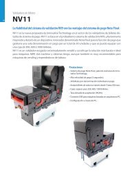
Sistema di lettura banconote NV9<br />
NV9 Bank note validator system<br />
Il futuro della Gestione Banconote Smiley ®<br />
The future of Smiley ® Bank Note Handling<br />
<strong><strong>Manual</strong>e</strong> <strong>Operativo</strong><br />
<strong>Operations</strong> <strong>Manual</strong><br />
GA326-3<br />
© Copyright Innovative Technology Limited 2
Gentile cliente,<br />
la ringraziamo per la fiducia accordataci con l’acquisto di un nostro prodotto.<br />
Se Lei avrà la costanza di seguire attentamente le indicazioni contenute nel presente manuale, siamo certi<br />
che potrà apprezzarne nel tempo e con soddisfazione la qualità.<br />
La preghiamo di leggere attentamente le indicazioni contenute nel manuale che riguardano l’uso corretto del<br />
nostro prodotto, in conformità alle prescrizioni essenziali di sicurezza.<br />
Dear Customer,<br />
Thank you for buying one of our products.<br />
If you carefully follow the indications included in this manual, we are sure you will appreciate our quality over<br />
time with full satisfaction.<br />
We kindly ask you to carefully read the instructions of this manual about the correct use of our product in<br />
accordance with the basic safety provisions.<br />
Sommario - Index<br />
STORIA DELLE VARIAZIONI DOCUMENTO.............................................................................................................4<br />
1: INTRODUZIONE ......................................................................................................................................................5<br />
2: OGGETTO DEL DOCUMENTO...............................................................................................................................6<br />
3: REQUISITI AMBIENTALI E DI ALIMENTAZIONE .................................................................................................7<br />
4: DESCRIZIONE GENERALE....................................................................................................................................8<br />
5: INTERFACCIA UTENTE CON NV9.........................................................................................................................9<br />
5.1: IMPOSTAZIONI DIPSWITCH .................................................................................................................................................9<br />
5.2: CODICI LED DI STATO ......................................................................................................................................................10<br />
6: INTERFACCIA MACCHINA: HARDWARE...........................................................................................................11<br />
6.1: DETTAGLI PIN CONNETTORE INTERFACCIA......................................................................................................................11<br />
6.2: CIRCUITI HARDWARE INGRESSO/USCITA.........................................................................................................................12<br />
6.3: INGRESSO E USCITE INTERFACCE SERIALI OPZIONALI SOFTWARE ................................................................................12<br />
7: INTERFACCIA MACCHINA: PROTOCOLLI ........................................................................................................13<br />
7.1: INGRESSO/USCITA PARALLELI...........................................................................................................................................13<br />
7.2: USCITA CORRENTE IMPULSI.............................................................................................................................................13<br />
7.3: USCITA BINARIA ................................................................................................................................................................14<br />
7.4: INGRESSO / USCITA SERIALE SEMPLICE..........................................................................................................................15<br />
7.5: PROTOCOLLO SICUREZZA SMILEY®– SSP .....................................................................................................................17<br />
7.6: MDB – BUS MULTI-DROP / PROTOCOLLO COMUNICAZIONI INTERNE (IF5) ...................................................................18<br />
7.7: PROTOCOLLO CCTALK......................................................................................................................................................19<br />
7.8: INTERFACCIA ESTESA – SERIALE USA ............................................................................................................................20<br />
8: AGGIORNAMENTO VALUTA E FIRMWARE.......................................................................................................21<br />
8.1: GESTIONE VALUTE............................................................................................................................................................21<br />
8.2: COPIA NV9 – NV9 (CLONAZIONE)...................................................................................................................................21<br />
8.3: PROCEDURA DI COPIATURA NV9 – NV9..........................................................................................................................22<br />
9: INSTALLAZIONE MECCANICA............................................................................................................................23<br />
9.1: SOSTITUZIONE O RIMOZIONE DELLE MASCHERE ..............................................................................................................23<br />
9.2: SOSTITUZIONE O RIMOZIONE CONTENITORI DENARO .......................................................................................................23<br />
10: MANUTENZIONE ORDINARIA ...........................................................................................................................24<br />
10.1: PULIZIA ...........................................................................................................................................................................24<br />
FIGURA 12: LETTORE NV9 ......................................................................................................................................................25<br />
10.2: SOSTITUZIONE CINGHIE ..................................................................................................................................................25<br />
10.2 RIMOZIONE RESIDUI DAL PERCORSO BANCONOTE / SOSTITUZIONE CINGHIE.................................................................26<br />
11: ANALISI RILEVAMENTO GUASTI .....................................................................................................................27<br />
12: STRUMENTI DI SUPPORTO...............................................................................................................................29<br />
12.1: SOFTWARE PC PROGRAMMAZIONE VALUTE .................................................................................................................29<br />
www.comesterogroup.it<br />
NV9 – IT/UK<br />
21/11/2005<br />
2/73
12.2: SUPPORTO SITO WEB INTERNET ....................................................................................................................................29<br />
12.3 : SUPPORTO E -MAIL........................................................................................................................................................29<br />
APPENDICE A – DISEGNO DIMENSIONI................................................................................................................30<br />
APPENDICE B - CONTROLLO ESCROW................................................................................................................35<br />
APPENDICE C - STRUMENTI INTERFACCIA DA1 - DA2 ......................................................................................36<br />
APPENDICE D – REGISTRAZIONE SU SITO WEB ................................................................................................37<br />
1 INTRODUCTION .....................................................................................................................................................40<br />
2: SCOPE OF DOCUMENT .......................................................................................................................................41<br />
3: ENVIRONMENT AND POWER REQUIREMENTS ...............................................................................................42<br />
4: GENERAL DESCRIPTION ....................................................................................................................................43<br />
5: NV9 USER INTERFACE........................................................................................................................................44<br />
5.1:DIPSWITCH SETTINGS.......................................................................................................................................................44<br />
5.2: LED STATUS CODES........................................................................................................................................................45<br />
6: INTERFACES: HARDWARE DESCRIPTION .......................................................................................................46<br />
6.1: INTERFACE CONNECTOR PIN DETAILS.............................................................................................................................46<br />
6.2: INPUT AND OUTPUT HARDWARE CIRCUITS......................................................................................................................46<br />
6.3: SOFTWARE OPTIONAL SERIAL INTERFACE INPUT AND OUTPUTS....................................................................................47<br />
7: MACHINE INTERFACES: PROTOCOLS .............................................................................................................48<br />
7.1: PARALLEL INPUT AND OUTPUT:.........................................................................................................................................48<br />
7.2:PULSE STREAM OUTPUT...................................................................................................................................................48<br />
7.3: BINARY OUTPUT - BIN......................................................................................................................................................49<br />
7.4:SIMPLE SERIAL INPUT/OUTPUT – SIO ..............................................................................................................................50<br />
7.5 SMILEY® SECURE PROTOCOL - SSP ...............................................................................................................................53<br />
7.6 MULTI-DROP BUS / INTERNAL COMMUNICATIONS PROTOCOL (IF5) – MDB ...................................................................54<br />
7.7 CCTALK PROTOCOL – CCT..............................................................................................................................................55<br />
7.8 EXTENDED INTERFACE / USA SERIAL – NIS ....................................................................................................................55<br />
8 UPDATING CURRENCY AND FIRMWARE...........................................................................................................56<br />
8.1 ITL BNV DOWNLOAD MANAGER.......................................................................................................................................56<br />
8.2 NV9 – NV9 COPY (CLONING)...........................................................................................................................................56<br />
8.3:NV9 – NV9 COPY PROCESS. ............................................................................................................................................57<br />
9: MECHANICAL INSTALLATION............................................................................................................................59<br />
9.1:CHANGING OR REMOVING THE BEZELS .............................................................................................................................59<br />
9.2:CHANGING OR REMOVING CASH BOXES ............................................................................................................................59<br />
10 ROUTINE MAINTENANCE...................................................................................................................................60<br />
10.1 CLEANING ........................................................................................................................................................................60<br />
10.2 NOTE PATH DEBRIS CLEARING / BELT CHANGING.........................................................................................................60<br />
10.2 NOTE PATH DEBRIS CLEARING / BELT CHANGING.........................................................................................................61<br />
11: FAULT FINDING ANALYSIS...............................................................................................................................62<br />
12 SUPPORT TOOLS ................................................................................................................................................64<br />
12.1 PC CURRENCY PROGRAMMING SOFTWARE (ITL BNV DOWNLOAD MANAGER)...........................................................64<br />
12.2 INTERNET WEBSITE SUPPORT.........................................................................................................................................64<br />
12.3 E-MAIL SUPPORT.............................................................................................................................................................64<br />
APPENDIX A - DRAWINGS.......................................................................................................................................65<br />
APPENDIX B - ESCROW CONTROL .......................................................................................................................70<br />
APPENDIX C - INTERFACE TOOLS DA1 - DA2......................................................................................................71<br />
APPENDIX D – WEBSITE REGISTRATION.............................................................................................................72<br />
www.comesterogroup.it<br />
NV9 – IT/UK<br />
21/11/2005<br />
3/73
<strong><strong>Manual</strong>e</strong> <strong>Operativo</strong> NV9 – GA326-3<br />
Storia delle variazioni documento<br />
Innovative Technology Ltd<br />
Titolo: <strong><strong>Manual</strong>e</strong> Tecnico NV10<br />
N.Disegno: GA326 Progetto:<br />
Autore: T.J. Crowley Data: 29/10/2004<br />
Formato: MS Word 2000<br />
Versione Data Mod. da Commenti<br />
Versione 1 20/07/2005 TJC Prima bozza<br />
Versione 2 08/08/2005 ATG Seconda bozza<br />
Versione 3 05/09/2005 RJS Edizione iniziale<br />
www.comesterogroup.it<br />
NV9 – IT<br />
21/11/2005<br />
4/73
<strong><strong>Manual</strong>e</strong> <strong>Operativo</strong> NV9 – GA326-3<br />
1: Introduzione<br />
Il presente manuale descrive il funzionamento del Lettore di Banconote NV9 installato con il Firmware Versione<br />
3.15 o superiore.<br />
Attenzione<br />
• Prima dell’utilizzo su questo prodotto deve essere installato un fusibile da 2 Amp.<br />
• Il Lettore NV9 è compatibile pin per pin con NV7/8/10, ma NON è compatibile pin per pin con i prodotti<br />
delle serie NV2/3/4/4X o 5<br />
Si raccomanda di prendere attenta visione del presente manuale in quanto contiene molte nuove caratteristiche<br />
che consentono nuovi utilizzi e maggior sicurezza nelle applicazioni.<br />
Se non comprendete qualche capitolo del presente manuale, contattate ITL per ricevere assistenza. In questo<br />
modo possiamo continuare a migliorare il nostro prodotto. In alternativa potete visitare il nostro sito web su<br />
www.innovative-technology.co.uk<br />
Innovative Technology Ltd.<br />
Derker Street<br />
Oldham<br />
England<br />
OL1 4EQ<br />
Tel: +44 (0) 161 626 9999<br />
Fax: +44 (0) 161 620 2090<br />
E-mail support@innovative-technology.co.uk<br />
Web site www.innovative-technology.co.uk<br />
Smiley® e il logo ITL sono marchi internazionali e sono di proprietà di Innovative Technology Limited.<br />
La Innovative Technology detiene una serie di Brevetti e di Brevetti in corso di registrazione sia europei che<br />
internazionali a protezione di questo prodotto. Se necessitate di maggiori dettagli, vogliate contattare<br />
l’azienda.<br />
La Innovative Technology non è responsabile di alcuna perdita, lesione o danno provocati dall’installazione<br />
ed utilizzo di questo prodotto. Ciò non influenza i vostri diritti in base alla normativa locale. In caso di dubbi<br />
vogliate contattare la Innovative Technology per i dettagli di eventuali variazioni.<br />
www.comesterogroup.it<br />
NV9 – IT<br />
21/11/2005<br />
5/73
<strong><strong>Manual</strong>e</strong> <strong>Operativo</strong> NV9 – GA326-3<br />
2: Oggetto del documento<br />
Il presente documento è rivolto a coloro che si occupano di:<br />
• Trasferire il progetto dell’NV9 in elementi di attrezzatura.<br />
• Realizzare attrezzature utilizzando NV9.<br />
• Installare attrezzature contenenti NV9.<br />
• Eseguire manutenzione su attrezzature contenenti NV9.<br />
Nonostante siano incluse informazioni che consentono un certo grado di diagnostica dei guasti e di riparazione, si<br />
raccomanda che per tutte le riparazioni meccaniche, tranne quelle semplici, l’unità venga inviata ad un centro<br />
assistenza qualificato per le riparazioni.<br />
Attenzione:<br />
• Non superare mai i limiti ambientali ed elettrici raccomandati.<br />
• Non cercare di lubrificare I meccanismi in quanto ciò potrebbe influire sul trasporto delle banconote.<br />
• Non levigare la lente in quanto ciò potrebbe alterare le caratteristiche ottiche.<br />
• Se il Lettore NV9 viene smontato, l’unità deve essere ritarata /reinizializzata a seguito del rimontaggio.<br />
La Innovative Technology Ltd persegue una politica di continuo miglioramento dei prodotti. Pertanto i prodotti forniti<br />
possono variare dalle specifiche qui descritte.<br />
www.comesterogroup.it<br />
NV9 – IT<br />
21/11/2005<br />
6/73
<strong><strong>Manual</strong>e</strong> <strong>Operativo</strong> NV9 – GA326-3<br />
3: Requisiti Ambientali e di Alimentazione<br />
Ambiente Minima Massima<br />
Temperatura +3 o C +50 o C<br />
Umidità 5% 95% senza<br />
condensa<br />
Tabella 1 – Requisiti Ambientali<br />
Attenzione:<br />
• Se la tensione di entrata scende al di sotto degli 11V, NV9 potrebbe non funzionare<br />
correttamente (rifiuto banconote). Il led di stato color giallo e le spie frontali della<br />
mascherina lampeggiano per indicare condizioni non corrette.<br />
• Si raccomanda che l’alimentazione elettrica utilizzata sia in grado di fornire almeno<br />
1.5 Amp.<br />
Alimentazione elettrica Minima Massima<br />
Limiti Assoluti Tensione alimentazione (V cc) 11V 15V<br />
Tensione alimentazione Versione MDB IF5 18V 42V<br />
Tensione di ondulazione alimentazione<br />
0.25V @100Hz<br />
CORRENTI DI ALIMENTAZIONE:<br />
Standby 0.35A<br />
In lettura<br />
1A<br />
Picco (motore stacker in stallo) 1.5A<br />
TABELLA 2 – REQUISITI DI ALIMENTAZIONE<br />
www.comesterogroup.it<br />
NV9 – IT<br />
21/11/2005<br />
7/73
<strong><strong>Manual</strong>e</strong> <strong>Operativo</strong> NV9 – GA326-3<br />
4: Descrizione Generale<br />
Lettore NV9 – la futura generazione dei lettori di banconote Smiley®<br />
Il Lettore di banconote NV9 è un lettore di banconote compatto (vedi figura 1), adatto per la maggior parte delle<br />
macchine funzionanti con denaro. Accetta fino a 15 diversi tagli di banconote in modalità di controllo seriale, in<br />
modalità ad impulsi e in modalità binaria, 4 banconote in modalità parallela ed è in grado di gestire diverse<br />
configurazioni di banconote aventi lo stesso valore così come sono presenti nel Regno Unito.<br />
DIPswitch<br />
LED di stato<br />
Contenitore denaro<br />
(stacker) ad<br />
inserimento<br />
Connettore<br />
interfaccia<br />
Braccio di<br />
fissaggio<br />
maschera<br />
Mascherina frontale<br />
orizzontale e verticale<br />
Figura 1 – NV9 con Mascherina verticale ed Universale<br />
Il lettore NV9 lascia la fabbrica dotato di almeno un set di dati relativi alla valuta in modo da essere pronto per una<br />
installazione immediata. Se si desidera variare il set di dati valuta, ciò si può fare mediante il sistema di clonazione<br />
valute da NV9 a NV9 oppure il software di gestione valute per PC.<br />
Vengono continuamente testate nuove valute e applicazioni; vogliate visitare il sito web www.innovativetechnology.co.uk<br />
o prendere contatto con la nostra azienda per informazioni riguardanti le valute specifiche se<br />
queste non fanno già parte del nostro elenco approvato.<br />
L’NV9 è stato realizzato per una facile installazione nella maggior parte delle macchine. Il nuovo “smile” consente<br />
l’inserimento delle banconote con una mano e semplifica il meccanismo di gestione delle stesse.<br />
L’interfacciamento con il Lettore è molto semplice, grazie alla scelta dei seguenti protocolli:<br />
• Uscite collettori aperte parallele<br />
• Uscita corrente impulsi<br />
• Comunicazioni seriali di sicurezza con Protocollo di Sicurezza Smiley® (SSP)<br />
• Binario<br />
• Comunicazioni seriali semplici<br />
• ccTalk<br />
• Protocollo interfaccia MDB<br />
• Interfaccia estesa/seriale USA<br />
www.comesterogroup.it<br />
NV9 – IT<br />
21/11/2005<br />
8/73
<strong><strong>Manual</strong>e</strong> <strong>Operativo</strong> NV9 – GA326-3<br />
5: Interfaccia Utente con NV9<br />
L’interfaccia utente con l’NV9 è indicata di seguito (vedi figura 2). Si tratta di un semplice LED rosso e verde e di<br />
una serie di quattro DIP switch. I LED indicano lo stato operativo dell’NV10 mentre i DIP switch impostano la<br />
modalità operativa di base dell’apparecchiatura.<br />
GIALLO<br />
O<br />
N<br />
1 2 3 4<br />
VERDE<br />
ROSSO<br />
STATUS<br />
1<br />
2<br />
3<br />
4<br />
Interfacce<br />
Moltiplicatore<br />
impulsi<br />
Parallela<br />
Impulso<br />
S.S.P.<br />
Speciale<br />
Figura 2 –Display utente e DIP switch NV10<br />
5.1: Impostazioni DIPswitch<br />
I quattro DIP switch possono essere impostati in una serie di regolazioni verso l’alto o il basso a seconda della<br />
configurazione richiesta per quel particolare NV9.<br />
Switch 1 – Riserva<br />
Switch 1 Attualmente senza funzione, riservato per un uso futuro<br />
Switch 2 – moltiplicatore di impulse<br />
Questo switch viene utilizzato per modificare il comportamento dell’interfaccia macchina selezionata. I dettagli della<br />
funzione di questo switch sono indicati nella descrizione interfacce del presente manuale.<br />
Attualmente l’unica interfaccia che fa uso di questo switch è la modalità a impulsi. In tale modalità lo switch può<br />
essere utilizzato per moltiplicare il numero di impulsi dato da un coefficiente di quattro. Quando lo switch è giù il<br />
moltiplicatore è 1, quando lo switch è su il moltiplicatore è 4.<br />
Switch 3 e 4 –Selezione protocollo Interfaccia Macchina<br />
Questi switch sono utilizzati per selezionare l’interfaccia macchina da utilizzare. L’NV9 supporta quattro interfacce,<br />
come indicato di seguito (vedi tabella 1).<br />
www.comesterogroup.it<br />
NV9 – IT<br />
21/11/2005<br />
9/73
<strong><strong>Manual</strong>e</strong> <strong>Operativo</strong> NV9 – GA326-3<br />
Interfaccia Switch 3 Switch 4<br />
Parallela Giù Giù<br />
Impulsi Giù Su<br />
SSP Su Giù<br />
Speciale Su Su<br />
Tabella 1 – Switch 3 e 4 - Selezione Interfaccia Macchina<br />
I dettagli delle interfacce parallela, a impulsi e SSP sono indicati nel capitolo relativo ai protocolli interfacce<br />
macchina del presente manuale.<br />
L’interfaccia speciale dipende dal firmware utilizzato nell’NV9, il firmware fornito come standard è l’interfaccia<br />
binaria (a livello mondiale) e CCTalk (solo Regno Unito). Ci sono in ogni caso altre opzioni che possono essere<br />
scaricate dall’utente:<br />
• Binaria<br />
• ccTalk<br />
• I/O semplice seriale ITL<br />
• MDB<br />
Le informazioni relative a ciascuna delle sopraindicate interfacce sono contenute nel “capitolo protocollo interfacce<br />
macchina” del presente manuale.<br />
5.2: Codici LED di stato<br />
I tre LED di stato sono posizionati alla sinistra dei DIPswitch sul lato destro dell’apparecchiatura e vengono<br />
impiegati per indicare una serie di segnali di stato.<br />
Lo stato rosso viene utilizzato per indicare problemi di sistema, quello verde per indicare la buona condizione del<br />
sistema; sono descritti di seguito in tabella 2.<br />
Stato LED<br />
A battito di cuore<br />
(Lento = periodo di 1 secondo)<br />
Rosso lampeggiante –periodo di un secondo<br />
Rosso lampeggiante rapidamente (rapido =<br />
periodo di mezzo secondo)<br />
Rosso fisso<br />
Lampeggiante alternativamente verde e rosso<br />
Lampeggiano le spie gialle e della mascherina<br />
Descrizione<br />
Nel normale funzionamento RUN, quando l’NV9 è<br />
pronto per leggere una banconota, il led di stato verde<br />
lampeggia lentamente (“a battito di cuore”) per<br />
segnalare uno stato “di salute”.<br />
NV9 è inceppato da qualche parte nel percorso<br />
banconote<br />
NV9 non riesce a tarare, il/i sensore/i può essere<br />
bloccato/i<br />
La memoria è stata corrotta<br />
Stacker pieno<br />
L’alimentazione elettrica non è corretta, verificare le<br />
specifiche<br />
Tabella 2 – Codici LED di stato<br />
www.comesterogroup.it<br />
NV9 – IT<br />
21/11/2005<br />
10/73
<strong><strong>Manual</strong>e</strong> <strong>Operativo</strong> NV9 – GA326-3<br />
6: Interfaccia macchina: hardware<br />
Il connettore interfaccia NV9 è posizionato sul lato sinistro dell’apparecchiatura. Dispone di 16 pin (vedi figura 3);<br />
due sono utilizzati per l’alimentazione elettrica 0v e +12v, vi poi sono cinque uscite e cinque entrate. I restanti<br />
quattro pin sono riservati per un futuro utilizzo. Un esempio di connettore adatto è il Molex Part. N. 39-51-2160.<br />
Connettore Interfaccia<br />
Figura 3 – Connettore Interfaccia<br />
6.1: Dettagli Pin Connettore Interfaccia<br />
I dettagli relativi ai pin connettore interfaccia sono indicati di seguito (vedi tabella 3): hanno una testata con passo<br />
0,1” e 2 file da 8 pin.<br />
Pin Nome Descrizione:<br />
1 Vend 1 (bit binario 1) Banconota accettata su Canale 1,<br />
Anche uscita Corrente a Impulsi<br />
Anche il pin uscita seriale in SSP e altre modalità seriali<br />
2 Vend 2 (bit binario 2) Banconota accettata su uscita impulsi Canale 2<br />
3 Vend 3 (bit binario 4) Banconota accettata su uscita impulsi Canale 3<br />
4 Vend 4 (bit binario 8) Banconota accettata su uscita impulsi Canale 4<br />
5 Inhibizione 1 Si inibisce il canale 1 tenendo questo pin IN ALTO. Per<br />
abilitare un canale l’inibizione deve essere tenuta IN BASSO.<br />
Anche il pin ingresso seriale per SSP e altre modalità seriali.<br />
6 Inhibizione 2 Si inibisce il canale 2 tenendo questo pin IN ALTO.<br />
7 Inhibizione 3 Si inibisce il canale 3 tenendo questo pin IN ALTO.<br />
8 Inhibizione 4 Si inibisce il canale 4 tenendo questo pin IN ALTO.<br />
9 Occupato NV8 è in fase di lettura e impilaggio all’uscita. Attivo basso<br />
mentre NV8 legge, trasporta o impila una banconota.<br />
10 Escrow Attivare la funzione Escrow ponendo IN BASSO, far<br />
riferimento al paragrafo Escrow nelle modalità parallela e<br />
binaria e all’ Appendice B per tutti I particolari.<br />
11 Riserva Riserva<br />
12 Riserva Riserva<br />
13 Riserva Riserva<br />
14 Riserva Riserva<br />
15 +Vin alimentazione 12V cc nominali<br />
16 0V Alimentazione 0v<br />
Tabella 3 – Dettagli connettore a 16 pin<br />
www.comesterogroup.it<br />
NV9 – IT<br />
21/11/2005<br />
11/73
<strong><strong>Manual</strong>e</strong> <strong>Operativo</strong> NV9 – GA326-3<br />
6.2: Circuiti Hardware Ingresso/Uscita<br />
Attenzione: Il segnale basso di uscita viene influenzato dal valore del resistore di salita sull’interfaccia<br />
macchina host. Verificare che i vostri livelli di BASSO sul segnale siano consoni alle<br />
specifiche della serie 74HC CMOS al fine di un funzionamento affidabile (vedi figura 4).<br />
Figura 4 – Circuito ingressi/uscite<br />
• Tutte le uscite sono transistor a collettore aperto.<br />
• Tutti gli ingressi vengono mantenuti alti su +5V interno via 10KΩ. La struttura degli ingressi è un gate CMOS<br />
dotato di una protezione antistatica.<br />
Livelli Logica Interfaccia Logica Bassa Logica Alta<br />
Ingressi 0V < Low < 0.5 +3.7V < High
<strong><strong>Manual</strong>e</strong> <strong>Operativo</strong> NV9 – GA326-3<br />
7: Interfaccia macchina: Protocolli<br />
Per selezionare l’interfaccia richiesta, I DIPswitch sul lato dell’NV9 devono essere impostati di conseguenza:<br />
7.1: Ingresso/uscita paralleli<br />
Per utilizzare uscite parallele, i DIPswitch 3 e 4 devono essere impostati giù.<br />
Segnali Vendita: (Pin 1 - 4). I quattro canali dispongono di proprie uscite singole. Se una banconota viene<br />
riconosciuta, allora la relativa linea del canale viene impostata su basso per 100+3 millisecondi. Gli impulsi oltre tali<br />
limiti dovrebbero essere respinti come precauzione per evitare un falso avvio dovuto al rumore.<br />
Uscita occupata: (Pin 9). Si tratta di un segnale di occupato generale. E’ attivato su basso mentre l’NV9 è in<br />
funzione.<br />
Controllo Escrow (Pin 10)-Modalità parallela: L’NV9 in questa modalità utilizza un programma escrow per singole<br />
banconote (vedi allegato Appendice B): : Ciò consente al lettore di trattenere la banconota una volta accettata e<br />
quindi impilare la stessa nel contenitore denaro solo quando la macchina host conferma il completamento<br />
dell’operazione di vendita. Se la conferma della vendita non viene ricevuta la banconota viene restituita al cliente<br />
dopo 30 secondi.<br />
Se la macchina host interrompe la transazione ponendo su alto il corrispondente ingresso di inibizione, la<br />
banconota viene restituita immediatamente.<br />
La macchina host può forzare la restituzione della banconota al cliente ponendo su alto la linea di inibizione in<br />
qualsiasi momento prima del termine della scadenza di 30 secondi. Ponendo su alto tutte le inibizioni la banconota<br />
verrà respinta.<br />
Qualora una banconota venisse forzatamente estratta dalla bocca dell’NV9 nel corso dell’intervallo dei 30 secondi,<br />
l’NV9 andrà fuori servizio per 45 secondi.<br />
Operazione di inibizione<br />
Ciascun canale (1 - 4) ha il proprio ingresso di inibizione per consentire alla macchina host di rifiutare specifiche<br />
banconote. Per inibire un canale, il relativo ingresso di inibizione deve essere mantenuto alto. Per abilitare un<br />
canale le corrispondenti inibizioni devono essere poste in basso in modo da consentire l’accettazione delle<br />
banconote.<br />
Se tutte e quattro le inibizioni sono in alto nello stesso momento, in tal caso l’NV9 non leggerà alcuna banconota.<br />
In questa modalità, se viene inserita una banconota, il motore andrà in retromarcia impedendo l’inserimento di una<br />
banconota e la mascherina non si illuminerà.<br />
Si possono collegare insieme tutte e quattro le inibizioni per creare un’inibizione “globale”. In tal modo l’NV9 può<br />
essere messo in servizio e fuori servizio dalla macchina host.<br />
7.2: Uscita Corrente Impulsi<br />
Per utilizzare l’uscita corrente impulsi per l’accettazione di un massimo di 16 canali/accettazione banconote, il DIP<br />
switch 3 deve essere in basso e il DIP switch 4 in alto.<br />
Segnale di Vendita (Pin 1): Quando una banconota viene riconosciuta, Vend 1 darà impulsi per un numero<br />
prestabilito di volte, il numero di impulsi e la relativa tempistica vengono impostati nel programma di gestione<br />
valute NV9 (e impostati su valori di default con il set di dati in dotazione).<br />
Il numero di impulsi viene moltiplicato per un coefficiente di quattro per I set dati relativi ai dollari USA, a seconda<br />
della posizione dello switch 2. Se lo switch è giù, allora il numero di impulsi è come programmato nell’uscita del set<br />
di dati. Se lo switch è su allora l’uscita è pari a quattro volte questo numero di impulsi.<br />
Uscita occupata: (Pin 9). Si tratta di un segnale di occupato generale. E’ attivo basso mentre l’NV9 è in funzione.<br />
Controllo Escrow: (pin 10). L’NV9 in questa modalità utilizza una funzione escrow per singole banconote (vedi<br />
allegato Appendice B): Ciò consente al lettore di trattenere la banconota una volta accettata e quindi impilare la<br />
stessa nel contenitore denaro solo quando la macchina host conferma il completamento dell’operazione di vendita.<br />
Se la conferma della vendita non viene ricevuta la banconota viene restituita al cliente dopo 30 secondi.<br />
Se la macchina host interrompe la transazione ponendo su alto il corrispondente ingresso di inibizione, la<br />
banconota viene restituita immediatamente.<br />
www.comesterogroup.it<br />
NV9 – IT<br />
21/11/2005<br />
13/73
<strong><strong>Manual</strong>e</strong> <strong>Operativo</strong> NV9 – GA326-3<br />
La macchina host può forzare la restituzione della banconota al cliente ponendo in alto la linea di inibizione in<br />
qualsiasi momento prima del termine della scadenza di 30 secondi. Ponendo in alto tutte le inibizioni la banconota<br />
verrà respinta.<br />
Qualora una banconota venisse forzatamente estratta dalla bocca dell’NV9 nel corso dell’intervallo dei 30 secondi,<br />
l’NV9 andrà fuori servizio per 45 secondi.<br />
Operazione di Inibizione: I canali (1 - 4) hanno il proprio ingresso di inibizione per consentire alla macchina host<br />
di rifiutare specifici valori di banconote. Per inibire un canale, il relativo ingresso di inibizione deve essere<br />
mantenuto alto. Per abilitare un canale la corrispondente inibizione deve essere posta in basso in modo da<br />
consentire l’accettazione delle banconote.<br />
Nota: I canali superiori a quattro non possono essere inibiti singolarmente ma verranno inibiti globalmente<br />
se vengono inibite le inibizioni da 1 a 4.<br />
Se tutte e quattro le inibizioni sono in alto nello stesso momento, l’NV9 non leggerà alcuna banconota. Si possono<br />
collegare insieme tutte e quattro le inibizioni per creare un’inibizione “globale”. In tal modo l’NV9 può essere messo<br />
in servizio e fuori servizio dalla macchina host.<br />
7.3: Uscita binaria<br />
Per utilizzare l’uscita binaria I DIP switch 3 e 4 devono entrambi essere su e l’opzione BIN del firmware di<br />
interfaccia deve essere caricata nell’NV9.<br />
Qualora la macchina necessitasse di più di 4 banconote da riconoscere, ma la macchina host non beneficiasse dei<br />
metodi di comunicazione seriale, l’NV9 potrà essere impostato in modo da fornire un’uscita modello binario sui<br />
quattro pin uscite parallele.<br />
Se l’NV9 è impostato in modalità binaria emetterà segnali di vendita come modello binario sulle uscite parallele per<br />
100+3ms. In tal modo possono essere accettate un massimo di 15 diverse banconote e 4 banconote inibite<br />
singolarmente.<br />
Segnali vendita (Pin 1 - 4). I quattro canali dispongono di proprie uscite singole. Se una banconota viene<br />
riconosciuta, allora la rappresentazione binaria del numero del canale verrà posta in basso per 100 + 3 ms. Gli<br />
impulsi oltre tali limiti verranno respinti come precauzione nei confronti di un falso avvio dovuto al rumore.<br />
Uscita occupata: (Pin 9). Si tratta di un segnale di occupato generale. E’ attivo basso mentre l’NV9 è in funzione.<br />
Controllo Escrow: (pin 10). L’NV9 in questa modalità utilizza una funzione escrow per singole banconote (vedi<br />
Appendice B). Ciò consente al lettore di trattenere la banconota una volta accettata e quindi impilare la stessa nel<br />
contenitore denaro solo quando la macchina host conferma il completamento dell’operazione di vendita. Se la<br />
conferma della vendita non viene ricevuta la banconota viene restituita al cliente dopo 30 secondi.<br />
Se la macchina host interrompe la transazione ponendo su alto il corrispondente ingresso di inibizione su pin 10, la<br />
banconota viene restituita immediatamente.<br />
La macchina host può forzare la restituzione della banconota al cliente ponendo in alto la linea di inibizione in<br />
qualsiasi momento prima del termine della scadenza di 30 secondi. Ponendo in alto tutte le inibizioni la banconota<br />
verrà respinta.<br />
Qualora una banconota venisse forzatamente estratta dalla bocca dell’NV9 nel corso dell’intervallo dei 30 secondi,<br />
l’NV9 andrà fuori servizio per 45 secondi.<br />
Operazione di Inibizione: I canali (1 - 4) hanno il proprio ingresso di inibizione per consentire alla macchina host<br />
di rifiutare specifiche banconote. Per inibire un canale, il relativo ingresso di inibizione deve essere mantenuto alto.<br />
Per abilitare un canale la corrispondente inibizione deve essere posta in basso in modo da consentire<br />
l’accettazione delle banconote.<br />
Nota: I canali superiori a quattro non possono essere inibiti singolarmente, ma verranno inibiti globalmente<br />
se vengono inibite le inibizioni da 1 a 4.<br />
Se tutte e quattro le inibizioni sono in alto nello stesso momento, in tal caso l’NV9 non leggerà alcuna banconota.<br />
Si possono collegare insieme tutte e 4 le inibizioni per creare un’inibizione “globale”. In tal modo l’NV9 può essere<br />
messo in servizio e fuori servizio dalla macchina host.<br />
www.comesterogroup.it<br />
NV9 – IT<br />
21/11/2005<br />
14/73
<strong><strong>Manual</strong>e</strong> <strong>Operativo</strong> NV9 – GA326-3<br />
7.4: Ingresso / Uscita Seriale Semplice<br />
Gli utenti dell’NV4 Smiley® già esistente probabilmente usano già il programma di ingresso/uscita seriali. Anche il<br />
lettore NV9 supporta detto sistema. In ogni caso tale interfaccia non è raccomandata per i nuovi modelli,<br />
l’interfaccia raccomandata è il Protocollo di Sicurezza Smiley® SSP.<br />
Attenzione:<br />
• NV9 non supporta la modalità semplice dei soli dati seriali in uscita come invece l’NV4. Supporta<br />
solamente la modalità Ingresso/Uscita dati seriali.<br />
• La macchina host non ritrasmette messaggi al lettore.<br />
• NV9 non opera in vera modalità RS232. (Solo a livello TTL)<br />
• NV9 non viene abilitato in modalità seriale I/O se la linea di inibizione 3 viene tenuta in basso con<br />
alimentazione inserita<br />
Per utilizzare la modalità seriale, I DIP switch 3 e 4 devono entrambi essere impostati in alto e l’opzione SIO della<br />
modalità seriale semplice del firmware di interfaccia deve essere caricata sull’NV9.<br />
Sono forniti I comandi per il controllo totale del funzionamento del lettore. Si possono impostare le banconote da<br />
accettare e respingere e può essere abilitata una modalità escrow singola. In modalità seriale semplice i comandi<br />
di byte vengono trasmessi al lettore, quest’ultimo ritrasmette ogni comando valido che riceve.<br />
La modalità seriale I/O supporta due velocità di baud; 300 baud quando l’Inibizione 2 viene posta in alto o lasciata<br />
fluttuare con corrente inserita e 9600 baud quando la linea Inibizione 2 viene tenuta bassa con corrente inserita. I<br />
dati vengono formattati come segue (vedi figura 5):<br />
1-start bit - 8 bit dati - 2 bit sto - 300 baud<br />
Vend 1(pin 1)<br />
idle avvio bit 0 bit 1 bit 2 bit 3 bit 4 bit 5 bit 6 bit 7 stop stop Min<br />
3.3ms<br />
0 0 1 0 1 0 0 0 = 20dec<br />
Figura- 5 Tipica Trasmissione Uscita Seriale del valore 20 (decimale). Banconota non Riconosciuta<br />
Il lettore NV9 riceve e trasmette i seguenti codici evento:<br />
www.comesterogroup.it<br />
NV9 – IT<br />
21/11/2005<br />
15/73
<strong><strong>Manual</strong>e</strong> <strong>Operativo</strong> NV9 – GA326-3<br />
Codici ricevimento Riconosciuti su NV9<br />
MESSAGGIO<br />
VALORE<br />
DECIMALE<br />
Codici Trasmessi da NV10<br />
MESSAGGIO<br />
VALORE<br />
DECIMALE<br />
Inibiz.C1 131 Accettazione banconota su C1 1<br />
Inibiz.C2 132 Accettazione banconota su C2 2<br />
Inibiz.C3 133 Accettazione banconota su C3 3<br />
Inibiz.C4 134 Accettazione banconota su C4 4<br />
Inibiz.C5 135 Accettazione banconota su C5 5<br />
Inibiz.C6 136 Accettazione banconota su C6 6<br />
Inibiz.C7 137 Accettazione banconota su C7 7<br />
Inibiz.C8 138 Accettazione banconota su C8 8<br />
Inibiz.C9 139 Accettazione banconota su C9 9<br />
Inibiz.C10 140 Accettazione banconota su C10 10<br />
Inibiz.C11 141 Accettazione banconota su C11 11<br />
Inibiz.C12 142 Accettazione banconota su C12 12<br />
Inibiz.C13 143 Accettazione banconota su C13 13<br />
Inibiz.C14 144 Accettazione banconota su C14 14<br />
Inibiz.C15 145 Accettazione banconota su C15 15<br />
Inibiz.C16 146 Accettazione banconota su C16 16<br />
Non inibiz. C1 151 Banconota non riconosciuta 20<br />
Non inibiz. C2 152 Funzionamento meccanismo lento 30<br />
Non inibiz. C3 153 Tentato Strimming 40<br />
Non inibiz. C4 154 Canale 5 Banconota respinta (canale<br />
50<br />
frodi)<br />
Non inibiz. C5 155 STACKER pieno o inceppato 60<br />
Non inibiz. C6 156 Interruzione durante Escrow 70<br />
Non inibiz. C7 157 La banconota può essere stata presa per<br />
80<br />
liberare l’inceppamento<br />
Non inibiz. C8 158 Lettore occupato 120<br />
Non inibiz. C9 159 Lettore non occupato 121<br />
Non inibiz. C10 160 Errore comando 255<br />
Non inibiz. C11 161<br />
Non inibiz. C12 162<br />
Non inibiz. C13 163<br />
Non inibiz. C14 164<br />
Non inibiz. C15 165<br />
Non inibiz. C16 166<br />
Abilita modalità escrow seriale 170<br />
Disabilita modalità escrow seriale 171<br />
Accetta Escrow 172<br />
Respinge Escrow 173<br />
Stato 182<br />
Abilita tutti 184<br />
Disabilita tutti 185<br />
Tabella 6 – Codici ricezione/trasmissione<br />
www.comesterogroup.it<br />
NV9 – IT<br />
21/11/2005<br />
16/73
<strong><strong>Manual</strong>e</strong> <strong>Operativo</strong> NV9 – GA326-3<br />
Esempi di transazione sono indicati di seguito (vedi tabella 7).<br />
Evento Lettore Valore Decimale Host<br />
Banconota inserita nel lettore Lettore Occupato 120 <br />
Banconota accettata canale 2 Lettore Pronto 121 <br />
Accetta su Canale 2<br />
2 <br />
Banconota inserita nel lettore Lettore Occupato 120 <br />
Banconota non riconosciuta Lettore Pronto 121 <br />
Banconota non riconosciuta 20 <br />
Il lettore ha restituito la banconota Lettore Pronto 121 <br />
Software Inibiz. Canale 4 Inibiz. C4 134 Inibiz. C4<br />
Channel 4 Inhibited<br />
134 <br />
Software Enable Channel 4 Uninhibit C4 154 Uninhibit C4<br />
Canale 4 inibito<br />
154 <br />
Report stato 182 Richiesta stato<br />
Messaggio di stato 3 byte Inibiz.stato canali 1-8 byte 1<br />
Inibiz.stato canali 9-16<br />
byte 2<br />
Escrow On (=1) / Off (=0) byte 3<br />
Attiva modalità Escrow 170 Abilita<br />
modalità<br />
Escrow<br />
Modalità Escrow abilitata 170 <br />
Accettaz.banconota in modalità<br />
Escrow<br />
Banconota inserita nel lettore Lettore Occupato 120 <br />
Banconota accettata canale 2 Lettore Pronto 121 <br />
Accetta su Canale 2<br />
2 <br />
172 Accetta<br />
banconota in<br />
Escrow<br />
Accetta Escrow<br />
172 <br />
Accetta su Canale 2<br />
2 <br />
7.5: Protocollo Sicurezza Smiley®– SSP<br />
Tabella 7 – Esempi di Protocolli<br />
Nota: Consultare le specifiche relative al Protocollo Sicurezza Smiley® (SSP) (Disegno ITL GA138) sul<br />
sito web per tutti i dettagli riguardanti tale Protocollo<br />
Per l’utilizzo della modalità SSP il DIP switch 3 deve essere impostato in alto e il DIP switch 4 in basso.<br />
SSP è un’interfaccia seriale di sicurezza specificamente concepita per gestire problemi occorsi ai sistemi di<br />
gestione denaro nelle macchine da gioco. Problemi quali scambio di dispositivo di accettazione, riprogrammazione<br />
dispositivi di accettazione e intercettazione linee vengono tutti gestiti. Questa interfaccia viene raccomandata per<br />
tutti i modelli nuovi.<br />
L’interfaccia utilizza un modello master slave, la macchina host funge da master e le periferiche (dispositivo<br />
accettazione banconote, dispositivo accettazione monete o hopper monete) fungono da slave.<br />
Il trasferimento dati avviene su un bus multi-drop che utilizza una trasmissione seriale asincrona con orologio con<br />
driver semplici a collettore aperto. L’integrità dei trasferimenti dati viene garantita dall’utilizzo di somme di controllo<br />
CRCR a 16 bit su tutti i pacchetti.<br />
Ciascun dispositivo SSP di un tipo particolare dispone di un numero seriale unico, tale numero viene utilizzato per<br />
convalidare ciascun dispositivo per il trasferimento di crediti prima che le transazioni possano avere luogo.<br />
Attualmente vengono forniti comandi per dispositivi di accettazione monete, dispositivi di accettazione banconote e<br />
hopper monete. Vengono supportate tutte le caratteristiche attuali di detti dispositivi.<br />
Caratteristiche:<br />
www.comesterogroup.it<br />
NV9 – IT<br />
21/11/2005<br />
17/73
<strong><strong>Manual</strong>e</strong> <strong>Operativo</strong> NV9 – GA326-3<br />
• Controllo seriale di Lettori e Hopper Banconote/Monete<br />
• sistema a 4 cavi (Tx, Rx, +V, Terra)<br />
• RS232 (similare) – driver a collettore aperto<br />
• Alta velocità a 9600 baud<br />
• Verifica errori CRC a 16 bit<br />
• Modalità Trasferimento Dati<br />
Vantaggi:<br />
• Provato sul campo<br />
• Interfacciamento semplice ed economico delle periferiche di transazione.<br />
• Controllo a sicurezza elevata sulle periferiche di uscita.<br />
• Protezione dalle frodi con lettori sostituiti.<br />
• Integrazione diretta nelle macchine host.<br />
• Standard aperto per uso universale.<br />
Per informazioni dettagliate e le specifiche complete dei protocolli, consultare il disegno ITL GA 138 per le<br />
specifiche SSP disponibile sul sito web ITL www.innovative-technology.co.uk .<br />
Per facilitare la realizzazione del software SSP, ITL può fornire su richiesta il Codice C di campione, controlli DLL e<br />
applicazioni Visual Basic. Contattare support@innovative-technology.co.uk .<br />
7.6: MDB – Bus Multi-Drop / Protocollo Comunicazioni Interne (IF5)<br />
Per utilizzare la modalità MDB occorre installare sul lettore NV10 una scatola di interfaccia IF5 e i DIP switch 3 e 4<br />
devono entrambi essere impostati in alto, con l’opzione MDB del firmware di interfaccia caricata sull’NV10.<br />
Nota:<br />
• Consultare le specifiche del Bus Multi-Drop relativamente alla disponibilità degli attuali<br />
circuiti di comando suggeriti.<br />
• NV10 supporta il protocollo MDB, versione 1, livello 1<br />
• Per informazioni dettagliate e le specifiche complete del protocollo fare riferimento a<br />
NAMA (www.vending.org )<br />
MDB definisce un’interfaccia bus seriale utilizzata nei distributori automatici elettrici (vedi figura 7). Si tratta di un<br />
sistema Master-Slave a 9600 Baud in cui il lettore di banconote MDB NV9 funge da slave a un controllore master.<br />
Un master è in grado di comunicare con 32 periferiche o slave. Il master è definito come Controllore Distributore<br />
Automatico (VMC).<br />
Slave MDB NV10<br />
Ricezione<br />
Trasmissione<br />
Segnale di terra<br />
Figura 7- Circuiti Ingresso/Uscita optoisolati MDB<br />
www.comesterogroup.it<br />
NV9 – IT<br />
21/11/2005<br />
18/73
<strong><strong>Manual</strong>e</strong> <strong>Operativo</strong> NV9 – GA326-3<br />
Al lettore di banconote MDB NV9 viene assegnato un indirizzo unico – 00110XXX binario (30H). Il VMC interroga<br />
il bus per rilevare la presenza dei lettori MDB NV9 o per ottenere informazioni relative allo stato attuale dei lettori<br />
stessi.<br />
I lettori rispondono quando viene loro richiesta un’attività mediante un riconoscimento, un riconoscimento negativo<br />
o una risposta specifica, a seconda dello stato del momento. Sono evitate le rotture dei bus in quanto i lettori<br />
rispondono a seguito di interrogazione esclusivamente da parte del VMC.<br />
Occorre impostare l’indicativo internazionale del paese in cui I lettori si troveranno ad operare. Si tratta<br />
dell’indicativo telefonico internazionale di quel paese. L’indicativo viene rappresentato con due bytes.<br />
Per gli USA l’indicativo del paese è 00 01<br />
Per la Gran Bretagna l’indicativo è 00 44<br />
Occorre altresì specificare per ciascun lettore il fattore di demoltiplicazione. Tutti i valori di banconote accettati<br />
devono essere divisibili in modo eguale per tale numero.<br />
• Questo numero verrebbe impostato a 100 (Hex 64) per l’Euro o la Gran Bretagna.<br />
• Il numero verrebbe impostato a 1000 (Hex 03E8) per la Romania.<br />
• Occorre altresì programmare per ciascun lettore il numero di cifre decimali.<br />
• Il numero verrebbe impostato a 2 per l’Euro o USA<br />
• Il numero verrebbe impostato a 3 per la Romania<br />
Adottando I suddetti numeri:<br />
• £5 verrebbe indicato come 5.00<br />
• £10 verrebbe indicato come 10.00<br />
• $1 verrebbe indicato come 1.00<br />
• 1K Rumeno verrebbe indicato come 1.000<br />
7.7: Protocollo ccTalk<br />
L’NV9 supporta il protocollo seriale CCTalk per un semplice interfacciamento con le macchine host che supportano<br />
detto protocollo.<br />
Per utilizzare la modalità CCTalk (in modalità binaria ecc.) impostare I DIPswitch 3 e 4 sull’utente in posizione Su<br />
al fine di selezionare la modalità “Speciale” sui lettori.<br />
L’NV9 deve avere caricato il software CCTalk che utilizza l’opzione “avanzata” sul programma di gestione valute.<br />
I collegamenti relativi ai pin sull’NV9 per il CCTalk sono indicati di seguito (vedi figura 7) con riferimento ai pin di<br />
collegamento sul connettore di interfaccia NV9.<br />
Nota: Per informazioni dettagliate e le specifiche complete del protocollo visitare il sito www.cctalk.org<br />
Figura 7- Pin collegamento ccTalk su NV9<br />
www.comesterogroup.it<br />
NV9 – IT<br />
21/11/2005<br />
19/73
<strong><strong>Manual</strong>e</strong> <strong>Operativo</strong> NV9 – GA326-3<br />
La chiave di crittografia di default viene impostata sul codice chiave stampato sull’etichetta dell’NV9. Se la chiave<br />
viene cambiata con una nuova chiave memorizzata dalla macchina host, la chiave può essere resettata su default<br />
procedendo come di seguito indicato:<br />
1. Togliere corrente sull’ NV9.<br />
2. Impostare tutti e 4 I DIPswitch su ALTO.<br />
3. Dare corrente (no comunicazioni ccTalk).<br />
4. A questo punto lampeggia il LED rosso.<br />
5. Posizionare in basso gli switch 1 e 2<br />
The code is now reset.<br />
7.8: Interfaccia estesa – Seriale USA<br />
L’interfaccia seriale USA è un protocollo per comunicazioni seriali ad interfaccia non isolata.<br />
Vi è una linea DATI singola di uscita dall’NV9. Vi sono tre linee di controllo, due dal controllore “ACCETTA<br />
ABILITA” e “INVIA” e una dai lettori “IRQ”.<br />
Attenzione:<br />
• Tenere presente che l’NV9 funziona con un’alimentazione elettrica di 12 volt cc.<br />
• La terra dell’NV9 deve essere collegata alla terra del sistema di controllo.<br />
• Per ulteriori dettagli relativi a questo protocollo consultare il manuale Interfaccia Serie 2000 (numero<br />
riferimento 20105-002850046-PS)<br />
Dettagli di Collegamento:<br />
Segnale<br />
NV8<br />
12v 15<br />
0v 16<br />
ACCETTA ABILITA 6<br />
INVIA 7<br />
IRQ (INTERROMP) 2<br />
DATI 1<br />
FUORI_SERVIZIO 3<br />
Tabella 8 – Interfaccia estesa seriale USA<br />
www.comesterogroup.it<br />
NV9 – IT<br />
21/11/2005<br />
20/73
<strong><strong>Manual</strong>e</strong> <strong>Operativo</strong> NV9 – GA326-3<br />
8: Aggiornamento valuta e firmware<br />
Nota: I lettori vengono forniti già programmati dalla fabbrica. Saltare questo capitolo a meno che i lettori<br />
debbano essere riprogrammati con una nuova banconota o una nuova valuta.<br />
Il Lettore NV9 può venire programmato solamente mediante il programma di gestione scaricamento valute ITL<br />
BNV 2.9.7 (o maggiore) o mediante clonazione da un’unità master.<br />
8.1: Gestione Valute<br />
Per utilizzare il software di gestione scaricamento ITL BNV, che viene fornito con una serie di valute. Il sistema vi<br />
richiederà di utilizzare un PC Windows 95/98/NT2000 o XP Professional, Pentium (© Microsoft e Intel).<br />
Un elenco delle valute attualmente supportate si trova nel nostro sito web e si possono scaricare nuove versioni da<br />
www.innovative-technology.co.uk Ulteriori dettagli disponibili su support@Innovative-technology.co.uk.<br />
Per la registrazione al primo log in, fare riferimento all’Appendice D.<br />
8.2: Copia NV9 – NV9 (Clonazione)<br />
Generalità<br />
Il lettore Banconote NV9 dispone di un sistema per copiare il proprio programma e impostazioni su un altro NV9. Il<br />
lettore “Master” trasmette I dati relativi alla valuta ed effettua l’upgrade del firmware dello slave. Per la clonazione<br />
si raccomanda di utilizzare il kit clonazione 2 (CK2).<br />
Requisiti<br />
• Il Master deve possedere un firmware 3.15 o superiore<br />
• Kit clonazione 2<br />
• Alimentazione 12V.<br />
Figura 8 – Kit Clonazione 2<br />
Configurazione di avviamento<br />
• Togliere corrente dalle unità slave e master.<br />
• Impostare I DIP switch 3 e 4 su basso per selezionare la modalità di interfaccia SSP su entrambi gli NV10.<br />
• Mediante il kit clonazione CK2 dell’NV9 collegare assieme le due unità come sopra (vedi figura 8).<br />
• Attivare l’alimentazione 12V.<br />
• L’unità Master aggiornerà il firmware slave se la versione del master è superiore a quella dello slave. Se il<br />
firmware master è inferiore allo slave, allora la procedura di copiatura viene interrotta.<br />
• Se master e slave hanno lo stesso firmware verrà trasferita solamente la valuta.<br />
www.comesterogroup.it<br />
NV9 – IT<br />
21/11/2005<br />
21/73
<strong><strong>Manual</strong>e</strong> <strong>Operativo</strong> NV9 – GA326-3<br />
8.3: Procedura di copiatura NV9 – NV9.<br />
• Collegare l’NV9 master allo slave mediante l’adattatore per le copie e attivare l’alimentazione 12V.<br />
• L’unità master lampeggerà con I LED ROSSO e VERDE se il connettore viene configurato correttamente.<br />
• ROSSO e VERDE su master lampeggiano insieme – tentativo di comunicazione con slave.<br />
• ROSSO e VERDE su master lampeggiano alternativamente – comunicazione stabilita, master in attesa del<br />
resettaggio slave.<br />
• Se la comunicazione è stata stabilita e lo slave ha effettuato il resettaggio, in tal caso il master leggerà la<br />
versione firmware dello slave e deciderà l’azione successiva.<br />
• Se il master non è compatibile con lo slave, i LED ROSSO e VERDE master lampeggeranno<br />
alternativamente al ritmo di 1 secondo. Non avverrà alcuna ulteriore azione di copiatura.<br />
• Se la versione firmware slave è superiore al master: i LED ROSSO e VERDE master lampeggeranno<br />
alternativamente al ritmo di 1 secondo. Non avverrà alcuna ulteriore azione di copiatura.<br />
• Se la versione firmware slave è la stessa del master, in tal caso il master darà inizio alla copiatura dei dati<br />
valuta sullo slave.<br />
• Se la versione firmware slave è inferiore al master, in tal caso il master darà inizio alla copiatura dei dati<br />
firmware sullo slave.<br />
Copia Firmware:<br />
Attenzione: Se il LED ROSSO master inizia a lampeggiare lentamente (1 al secondo) allora si è persa la<br />
comunicazione e la copiatura dovrebbe essere ricominciata dall’inizio.<br />
• Il LED ROSSO master lampeggia rapidamente durante la copiatura del firmware (di tanto in tanto il LED fa<br />
una pausa).<br />
• Se il LED ROSSO master inizia a lampeggiare lentamente (1 al secondo) allora si è persa la<br />
comunicazione e la copiatura dovrebbe essere ricominciata dall’inizio.<br />
• Quando la copia firmware è completa, lo slave effettuerà il resettaggio e l’unità Master attenderà di<br />
ristabilire le comunicazioni (LED lampeggia come all’accensione di primo livello).<br />
• Quando lo slave è pronto, il master inizia a copiare I dati valuta.<br />
Copia valuta:<br />
Attenzione: Se il LED ROSSO master inizia a lampeggiare lentamente (1 al secondo) allora si è persa la<br />
comunicazione e la copiatura dovrebbe essere ricominciata dall’inizio.<br />
• Il LED VERDE Master lampeggia rapidamente durante il processo di copiatura della valuta (di tanto in<br />
tanto il LED fa una pausa).<br />
• Al completamento della copia valuta, il Master mostrerà continuativamente i LED ROSSO e VERDE e lo<br />
slave procederà al resettaggio.<br />
• La copia NV9 – NV9 adesso è completa.<br />
www.comesterogroup.it<br />
NV9 – IT<br />
21/11/2005<br />
22/73
<strong><strong>Manual</strong>e</strong> <strong>Operativo</strong> NV9 – GA326-3<br />
9: Installazione meccanica<br />
I lettori NV9 possono essere forniti con l’una o l’altra delle seguenti maschere di introduzione, (vedi figura 9):<br />
Maschera<br />
Maschera verticale PA256<br />
Maschera verticale con<br />
Introduzione sporgente PA190<br />
Maschera verticale con<br />
introduzione sporgente PA191<br />
Figure 9 – Maschere di introduzione disponibili per NV9<br />
9.1: Sostituzione o rimozione delle maschere<br />
Attenzione: Accertarsi sempre che entrambi I bracci di fissaggio siano bene in posizione al fine di evitare danni<br />
Premere entrambi I bracci di fissaggio rossi in modo che questi si sgancino dai lati della mascherina. La<br />
mascherina può venire quindi sganciata dai 6 punti di fissaggio, (vedi figura 10). Per il riposizionamento premere la<br />
mascherina sui sei punti di fissaggio (3 su ciascun lato). I bracci rossi di fissaggio scatteranno nuovamente per<br />
tenere in posizione la mascherina.<br />
Punti di fissaggio<br />
Maschera<br />
Punti di fissaggio<br />
Braccio rosso per<br />
fissaggio maschera<br />
Figura 10 - Rimozione mascherina e lettore<br />
9.2: Sostituzione o rimozione contenitori denaro<br />
I lettori NV9 possono venire altresì forniti con diverse opzioni di contenitori denaro, (vedi figura 11).<br />
Contenitore Denaro a inserimento<br />
Contenitore Denaro a scorrimento<br />
Figure 11 - Contenitore Denaro a scorrimento Contenitore denaro a inserimento<br />
www.comesterogroup.it<br />
NV9 – IT<br />
21/11/2005<br />
23/73
<strong><strong>Manual</strong>e</strong> <strong>Operativo</strong> NV9 – GA326-3<br />
A inserimento da 300 banconote (particolare n. PA185) solamente per le versioni con mascherina verticale.<br />
• A scorrimento per 300 banconote (particolare n. PA192) per le versioni con mascherina orizzontale e<br />
verticale.<br />
• A inserimento da 600 banconote (particolare n. PA193) solamente per le versioni con mascherina<br />
verticale.<br />
• A scorrimento per 600 banconote (particolare n. PA194) per le versioni con mascherina orizzontale e<br />
verticale.<br />
• Con possibilità di chiusura da 300 banconote solamente per la versione con mascherina orizzontale<br />
(particolare n. PA186) (La chiusura non viene fornita –utilizzare con Chiusura a paletto tipo 6086-00KAL06<br />
con camma inclusa)<br />
10: Manutenzione ordinaria<br />
Il lettore NV9 è stato concepito per minimizzare qualsiasi variazione di prestazione nel tempo. Gran parte di quanto<br />
sopra viene ottenuto grazie ad un’attenta progettazione hardware e software.<br />
Tuttavia, a seconda dell’ambiente in cui viene installato, a un certo punto l’NV9 può richiedere pulizia, sostituzione<br />
cinghie o addirittura una nuova taratura.<br />
ATTENZIONE:<br />
NON UTILIZZARE DETERSIVI A BASE DI SOLVENTI COME ALCOOL,<br />
BENZINA, ALCOOL DENATURATI CON METANOLO O DETERSIVO CON<br />
PCB. CIO’ PROVOCHEREBBE DANNI PERMANENTI AL LETTORE,<br />
UTILIZZARE SEMPRE UN DETERGENTE NEUTRO.<br />
10.1: Pulizia<br />
Per la pulizia, far scorrere il dispositivo di rilascio rosso all’estremità del lettore NV9 per aprire il percorso<br />
banconote. Adesso il percorso banconote e la losanga sono esposti e possono essere puliti. Strofinare con cura le<br />
superfici con uno straccio morbido senza sfilacciature imbevuto precedentemente con acqua e soluzione<br />
detergente neutra (es. detersivo per lavare i piatti).<br />
Fare particolare attenzione attorno a tutte le lenti dei sensori (vedere figura 12), controllando che siano pulite e<br />
asciutte. Attenzione: Per pulire I sensori frontali “nascosti” utilizzare una spazzolina morbida o un batuffolo di<br />
cotone.<br />
Se una lente presenta graffi importanti, non cercare di levigarla. Contattare ITL per ulteriori ragguagli, in quanto vi<br />
possono essere danni alle proprietà ottiche della lente.<br />
Attenzione<br />
Per la pulizia del Sensore Frontale “nascosto”, utilizzare una spazzolina morbida o una<br />
batuffolo di cotone.<br />
www.comesterogroup.it<br />
NV9 – IT<br />
21/11/2005<br />
24/73
<strong><strong>Manual</strong>e</strong> <strong>Operativo</strong> NV9 – GA326-3<br />
Dispositivo di<br />
rilascio rosso<br />
Sensore ottico<br />
Sensori frontali<br />
Sensore di<br />
avviamento<br />
Sensore<br />
posteriore<br />
Sensore ottico<br />
Figura 12: Lettore NV9<br />
10.2: Sostituzione cinghie<br />
• Con I percorsi banconote NV10 esposti (vedi figura 10) posizionare l’apparecchiatura su una superficie<br />
pulita e asciutta.<br />
• Togliere la piastra di copertura inferiore sollevando il fermo di fissaggio e farla scivolare all’indietro con<br />
attenzione (vedi figura 11).<br />
• Premere le 2 molle di tensionamento cinghie verso l’interno quindi far scivolare ciascuna cinghia dal<br />
corpo dell’apparecchiatura, prima le ruotine più piccole.<br />
• Riposizionare le cinghie installandole sulle gambe del corpo del gruppo di comando, prima le ruotine più<br />
piccole.<br />
• Inserire la piastra di copertura inferiore nelle fessure di inserimento (2 su ciascun lato) premendo in<br />
avanti e verso il basso; la piastra si inserirà correttamente con un “click”.<br />
• Ricollegare insieme il percorso banconote superiore e quello inferiore.<br />
www.comesterogroup.it<br />
NV9 – IT<br />
21/11/2005<br />
25/73
<strong><strong>Manual</strong>e</strong> <strong>Operativo</strong> NV9 – GA326-3<br />
10.2 Rimozione residui dal percorso banconote / Sostituzione cinghie<br />
Per accedere al percorso banconote e alla losanga, far scorrere il dispositivo di rilascio rosso all’estremità del<br />
Lettore NV9 e sollevare per aprire. Premere il dispositivo di rilascio losanga e sollevare; ora il percorso banconote<br />
e la losanga sono esposti e si può eseguirne la manutenzione (vedere figura 13).<br />
Cinghie<br />
Dispositivo di<br />
rilascio rosso<br />
Losanga<br />
Dispositivo<br />
rilascio losanga<br />
Gruppo cavi<br />
completo<br />
Piastra Spintore<br />
Stacker banconote<br />
Piastra a molla<br />
contenitore<br />
Percorso<br />
banconote<br />
Figura 13 - Accesso Percorso banconote e losanga NV9<br />
Rimozione residui<br />
Esaminare I percorsi banconote, la losanga e lo stacker banconote per vedere se sono presenti sporcizia o residui.<br />
Pulire e strofinare con cura le superfici con uno straccio morbido senza sfilacciature imbevuto precedentemente<br />
con acqua e soluzione detergente neutra (es. detersivo per lavare i piatti). Fare particolare attenzione attorno a<br />
tutte le lenti dei sensori (vedere figura 12), assicurandosi che siano pulite e asciutte.<br />
Assicurarsi che lo stacker banconote e la piastra a molla del contenitore denaro non siano bloccati.<br />
Sostituzione Cinghie<br />
Con la losanga NV9 esposta (vedere figura 13) scollegare con attenzione il connettore inferiore del “gruppo cavi<br />
completo” dalla losanga.<br />
Rimuovere e posizionare la losanga su una superficie asciutta e pulita e togliere le cinghie, facendole scorrere<br />
prima sulle ruotine più piccole.<br />
Riposizionare le cinghie eseguendo la procedura al contrario.<br />
www.comesterogroup.it<br />
NV9 – IT<br />
21/11/2005<br />
26/73
<strong><strong>Manual</strong>e</strong> <strong>Operativo</strong> NV9 – GA326-3<br />
11: Analisi rilevamento guasti<br />
Le banconote non vengono impilate correttamente<br />
SI<br />
Il contenitore denaro/lo<br />
scivolo banconote sono<br />
installati correttamente?<br />
NO<br />
Verificare che non vi siano danni al<br />
contenitore denaro/scivolo banconote<br />
Installare correttamente il<br />
contenitore denaro/scivolo<br />
banconote<br />
Verificare che sia installato il<br />
contenitore denaro adatto per NV9<br />
Fine<br />
Figura 12 - Le banconote non vengono impilate in modo corretto<br />
Le banconote passano attraverso il lettore<br />
ma non danno un segnale di vendita<br />
SI<br />
L’alimentazione<br />
elettrica rientra nelle<br />
specifiche?<br />
NO<br />
Verificare che siano selezionate le<br />
corrette impostazioni DIPswitch<br />
Verificare che siano presenti la<br />
corretta alimentazione e corrente a<br />
Verificare il sistema di interfaccia<br />
Fine<br />
Figura 13 - Le banconote passano nei lettori senza segnale di vendita<br />
L’apparecchiatura respinge banconote valide<br />
SI<br />
Verificare l’impostazione relativa<br />
alla sicurezza<br />
L’apparecchiatura è<br />
stata programmata per<br />
questa banconota?<br />
NO<br />
Verificare la valuta<br />
sull’etichettal<br />
Regolare per correggere le<br />
impostazioni relative alla sicurezza<br />
Programmare l’apparecchiatura<br />
Eseguire la prova diagnostica<br />
sensori delle lenti<br />
Fine<br />
Figure14 – L’apparecchiatura respinge banconote valide<br />
www.comesterogroup.it<br />
NV9 – IT<br />
21/11/2005<br />
27/73
<strong><strong>Manual</strong>e</strong> <strong>Operativo</strong> NV9 – GA326-3<br />
Il lettore non prende le banconote<br />
YES<br />
La mascherina è<br />
illuminata?<br />
NO<br />
Verificare che I pin e I gruppi di<br />
comando e superiore<br />
dell’apparecchiatura siano collegati<br />
Verificare l’alimentazione elettrica<br />
Verificare le inibizioni<br />
Testare il cavo di collegamento<br />
Verificare il sistema interfacce<br />
Verificare le cinghie di trascinamento<br />
Verificare le lenti<br />
Fine<br />
Figura 15 - Il lettore non prende le banconote<br />
Il lettore funziona in modo lento o intermittente<br />
NO<br />
Sono presenti corpi<br />
estranei all’interno del<br />
percorso banconote?<br />
YES<br />
Il livello di<br />
tensione alimentazione<br />
è corretto?<br />
NO<br />
SI<br />
Pulire il percorso banconote<br />
Verificare eventuali danni<br />
Verificare che l’alimentazione sia corretta<br />
e la corrente sufficiente<br />
Sostituire I componenti<br />
danneggiati<br />
Verificare che non vi sia grasso sulle<br />
cinghie di trascinamento<br />
Sostituire le cinghie di trascinamento<br />
Fine<br />
www.comesterogroup.it<br />
NV9 – IT<br />
21/11/2005<br />
28/73
<strong><strong>Manual</strong>e</strong> <strong>Operativo</strong> NV9 – GA326-3<br />
Figura 16 - Il lettore funziona in modo lento o intermittente<br />
12: Strumenti di supporto<br />
Sono disponibili I seguenti strumenti di supporto da utilizzare con il Lettore Banconote NV9:<br />
1. Software per PC Gestione Valute.<br />
2. Possibilità di scaricare dal sito web Innovative Technology Ltd: www.innovative-technology.co.uk<br />
3. Supporto e-mail support@innovative-technology.co.uk<br />
12.1: Software PC Programmazione Valute<br />
Il software di Gestione Valute NV9 offre le seguenti funzioni:<br />
• Programmazione del lettore NV9 mediante scaricamento di dati valuta già preparati mediante il link di<br />
comunicazione seriale che utilizza il kit DA o il kit DA2 attraverso il link USB.<br />
• Verifica della versione firmware e valuta impostata già caricate su un’unità NV9.<br />
• Regolazione in base alle vostre esigenze del canale e della configurazione impulsi su un NV10 preprogrammato.<br />
• Scaricamento di una nuova versione di firmware sull’ NV9.<br />
• Utilizzo di funzioni diagnostiche per verificare il funzionamento del lettore (solo versione firmware 3.15 e<br />
superiore).<br />
Il software funziona su un Personal Computer IBM compatibile con processore Pentium o equivalente e richiede<br />
l’installazione di un kit DA1 sulla porta seriale o di un kit DA2 sulla porta USB a seconda del sistema operativo in<br />
uso (vedi Appendice C).<br />
12.2: Supporto sito web Internet<br />
Il sito web della Innovative Technology Ltd fornisce i mezzi per scaricare nuove serie di valute aggiornate e nuove<br />
versioni di firmware per l’ NV9. Visitate il sito www.innovative-technology.co.uk per registrare il vostro nome<br />
utente e avere accesso alla password per ulteriori dettagli, aggiornamenti e comunicati tecnici altresì disponibili.<br />
Per la registrazione al primo log in, consultare l’ Appendice D.<br />
12.3 : Supporto E -mail<br />
Se i dati di cui avete bisogno non sono disponibili sui supporti Internet, la Innovative Technology supporta un<br />
sistema e-mail per fornire assistenza ai clienti in caso di esigenze particolari.<br />
L’indirizzo è il seguente: support@innovative-technology.co.uk<br />
www.comesterogroup.it<br />
NV9 – IT<br />
21/11/2005<br />
29/73
Appendice A – Disegno dimensioni<br />
<strong><strong>Manual</strong>e</strong> <strong>Operativo</strong> NV9 – GA326-3<br />
www.comesterogroup.it<br />
NV9 – IT<br />
21/11/2005<br />
30/73
<strong><strong>Manual</strong>e</strong> <strong>Operativo</strong> NV9 – GA326-3<br />
www.comesterogroup.it<br />
NV9 – IT<br />
21/11/2005<br />
31/73
<strong><strong>Manual</strong>e</strong> <strong>Operativo</strong> NV9 – GA326-3<br />
www.comesterogroup.it<br />
NV9 – IT<br />
21/11/2005<br />
32/73
<strong><strong>Manual</strong>e</strong> <strong>Operativo</strong> NV9 – GA326-3<br />
www.comesterogroup.it<br />
NV9 – IT<br />
21/11/2005<br />
33/73
<strong><strong>Manual</strong>e</strong> <strong>Operativo</strong> NV9 – GA326-3<br />
www.comesterogroup.it<br />
NV9 – IT<br />
21/11/2005<br />
34/73
Appendice B - Controllo ESCROW<br />
<strong><strong>Manual</strong>e</strong> <strong>Operativo</strong> NV9 – GA326-3<br />
L’ NV9 dispone di un programma escrow per singole banconote (pin 10). Ciò consente al lettore di trattenere la<br />
banconota una volta accettata e quindi impilare la stessa nel contenitore denaro solo quando la macchina host<br />
conferma il completamento dell’operazione di vendita. Se la conferma della vendita non viene ricevuta la<br />
banconota viene restituita al cliente dopo 30 secondi. (vedi figura 19).<br />
Accettazione<br />
Escrow<br />
Segnale Vendita<br />
30sec Max<br />
Non attendere il secondo<br />
segnale di conferma<br />
vendita per oltre 30<br />
secondi<br />
Rifiuto Escrow<br />
100ms<br />
100ms<br />
Escrow tenuto in basso<br />
Segnale Vendita<br />
Inibizione<br />
Il rifiuto inibizione può avvenire<br />
in qualsiasi momento nel<br />
periodo di decisione di 30<br />
secondi dopo il completamento<br />
della vendita<br />
Figura 17 - Diagramma Temporale Escrow per Vendite Parallele<br />
Se la macchina host interrompe la transazione ponendo il corrispondente ingresso di inibizione in alto su pin 10, la<br />
banconota viene restituita immediatamente. La sequenza delle operazioni è la seguente:<br />
1. Pin 10 tenuto in basso in attesa dell’inserimento banconota.<br />
2. Banconota inserita. Il lettore emette un impulso da 100ms sul relativo canale.<br />
3. La macchina host dà inizio alla procedura di vendita.<br />
4. La macchine host pone il pin 10 in alto per indicare che vuole la banconota. Se ciò non viene fatto<br />
entro 30 secondi il lettore restituisce la banconota.<br />
5. Il lettore emette un impulso da 100ms sul relativo canale dopo che il pin 10 si è posto in alto per<br />
indicare l’accettazione definitiva della banconota. Se il segnale non viene ricevuto entro 30<br />
secondi, significa che il cliente ha forzatamente ripreso la banconota e la vendita verrà interrotta.<br />
6. Il processo di vendita è completato.<br />
7. La macchina host pone il pin 10 in basso in attesa della vendita successiva.<br />
La macchina host può forzare la restituzione della banconota al cliente ponendo in alto la linea di inibizione in<br />
qualsiasi momento prima del termine della scadenza di 30 secondi. Per i canali oltre il 4, ponendo in alto tutte le<br />
inibizioni la banconota verrà respinta.<br />
Qualora una banconota venisse forzatamente estratta dalla bocca dell’NV9 nel corso dell’intervallo dei 30 secondi,<br />
l’NV9 andrà fuori servizio per 45 secondi.<br />
Note: Controllo Escrow (modalità SSP): La funzione Escrow è altresì possibile mediante l’interfaccia<br />
seriale SSP. Le specifiche SSP GA138 disponibili sul sito web www.innovative-technology.co.uk.<br />
www.comesterogroup.it<br />
NV9 – IT<br />
21/11/2005<br />
35/73
<strong><strong>Manual</strong>e</strong> <strong>Operativo</strong> NV9 – GA326-3<br />
Appendice C - Strumenti Interfaccia DA1 - DA2<br />
I kit DA 1/ 2 sono concepiti per quanto segue:<br />
• Connettere i lettori banconote ITL a un PC per l’upgrade dei dati e del firmware relativo alle banconote.<br />
• Testare i lettori banconote NV9 indipendentemente dalla macchina host per confermare che il lettore<br />
funziona, ma è probabile che la macchina host inibisca alcuni canali.<br />
The DA1 and DA2 Kit comprise of the following components:<br />
DA1<br />
Scheda adattatore DA1 (PA167)<br />
Cavo Adattatore su Lettore NV9 ©<br />
CD-ROM di supporto ITL per DA1<br />
Cavo alimentazione<br />
Guida installazione<br />
DA2<br />
Scheda adattatoreDA2<br />
Cavo USB da tipo A a tipo B<br />
CD-ROM di supporto ITL per DA2<br />
Cavo da DA2 a NV9<br />
Cavo alimentazione<br />
Guida installazione<br />
Collegamento di un DA1 a un lettore e PC<br />
Se si utilizzano i sistemi operativi Windows 95/98/NT, Pentium (© Microsoft e Intel) collegare il DA1 al lettore<br />
come sotto indicato (vedi figura 1), mediante il connettore da 16 vie a 5 vie. La spina a jack da 3.5 mm e le 2 spine<br />
a banana vengono utilizzate per fornire corrente al DA1. Dare +12 volts alla spina rossa a banana e TERRA (0V)<br />
alla spina nera.<br />
Inserire il connettore tipo D a 9 vie nella porta seriale del PC e prendere nota del numero della porta in quanto<br />
questo sarà necessario successivamente per la configurazione del software. Dopo aver effettuato le connessioni<br />
installare il software relativo al lettore in uso.<br />
Figura 1 – Collegamento DA1 a un NV10 e PC per upgrading<br />
Collegamento di un DA2 a un lettore e PC<br />
Se si utilizzano I sistemi operativi Windows Pentium (© Microsoft e Intel) 98, 98SE, 2000, XP Home o XP<br />
Professional , collegare il DA2 al lettore come sotto indicato (vedi figura 2), mediante il connettore da NV10 a DA2.<br />
La spina a jack da 3.5 mm e le 2 spine a banana vengono utilizzate per fornire corrente al DA2. Dare +12 volts alla<br />
spina rossa a banana e TERRA (0V) alla spina nera.<br />
Inserire il connettore USB tipo A nella porta USB del PC. Dopo aver effettuato le connessioni installare il software<br />
relativo al lettore in uso.<br />
PC Porta USB<br />
+ 12V DC<br />
Figura 2 – Collegamento DA2 a un NV9 e PC per upgrade<br />
Installazione Software<br />
Per installare il software per l’upgrade dei set di dati e del firmware, inserire il CDROM nel drive del PC. Apparirà<br />
un menù di installazione, selezionare il prodotto che si desidera scaricare e selezionare il software che si desidera<br />
utilizzare. Seguire le istruzioni a video per completare l’installazione. Le istruzioni relative alla configurazione ed<br />
utilizzo del software installato si trovano nell’aiuto in linea per quel particolare software.<br />
In caso di ulteriore assistenza contattare support@innovative-technology.co.uk<br />
Lettore<br />
www.comesterogroup.it<br />
NV9 – IT<br />
21/11/2005<br />
36/73
Appendice D – Registrazione su sito web<br />
<strong><strong>Manual</strong>e</strong> <strong>Operativo</strong> NV9 – GA326-3<br />
Errore. Non si possono creare oggetti dalla modifica di codici di campo.<br />
Spostare il cursore del<br />
mouse sul pulsante<br />
“supporto” (support) e<br />
cliccare sulla voce<br />
“Scarica Valute“<br />
(currency download)<br />
Se siete già registrati,<br />
inserite username e<br />
password e cliccate su<br />
“login” per entrare.<br />
Se invece non siete registrati,<br />
cliccate sulla scritta “click here”.<br />
www.comesterogroup.it<br />
NV9 – IT<br />
21/11/2005<br />
37/73
<strong><strong>Manual</strong>e</strong> <strong>Operativo</strong> NV9 – GA326-3<br />
Inserite qui il nome<br />
della vostra azienda!<br />
Per la registrazione è<br />
necessario un indirizzo e-mail<br />
Per la registrazione è<br />
necessario un indirizzo e-mail<br />
Selezionate un’occupazione per<br />
descrizione della vostra attività.<br />
Scegliete una<br />
password ed inseritela<br />
i!<br />
Dopo che avete completato tutte le<br />
informazioni, cliccate su „Registra<br />
Dettagli“! Dopo circa 10 minuti il vostro<br />
account sarà pronto per il log in.<br />
www.comesterogroup.it<br />
NV9 – IT<br />
21/11/2005<br />
38/73
NV9 <strong>Operations</strong> <strong>Manual</strong> GA326-3<br />
Revision History<br />
Innovative Technology Ltd<br />
Title: NV9 Engineers <strong>Manual</strong><br />
Drawing No: GA326 Project:<br />
Author: T. J. Crowley Date: 29/10/2004<br />
Format: MS Word 2000<br />
Issue Rel Date Mod By Comments<br />
Issue 1 20/07/2005 TJC First draft<br />
Issue 2 08/08/2005 ATG Second draft<br />
Issue 3 05/09/2005 RJS First Release<br />
© Copyright Innovative Technology Limited 2005 NV9 – UK<br />
21/11/2005<br />
39/73
NV9 <strong>Operations</strong> <strong>Manual</strong> GA326-3<br />
1 Introduction<br />
This manual describes the operation of the NV9 Bank note Validator as fitted with Firmware Version 3.15 or<br />
greater.<br />
Caution<br />
• This Product must be fitted with a 2 Amp fuse before use.<br />
• The NV9 Validator is pin for pin compatible with NV7/8/10 but NOT pin for pin compatible with the<br />
NV2/3/4/4X or 5 series products.<br />
We recommend that you study this manual as there are many new features permitting new uses and more secure<br />
applications.<br />
If you do not understand any part of this manual please contact the factory for assistance. In this way we may<br />
continue to improve our product. Alternatively visit our web site at www.innovative-technology.co.uk<br />
Innovative Technology Ltd.<br />
Derker Street<br />
Oldham<br />
England<br />
OL1 4EQ<br />
Tel: +44 (0) 161 626 9999<br />
Fax: +44 (0) 161 620 2090<br />
Email: support@innovative-technology.co.uk<br />
Web site www.innovative-technology.co.uk<br />
Smiley® and the ITL Logo are international registered trademarks and they are the property of Innovative<br />
Technology Limited.<br />
Innovative Technology has a number of European and International Patents and Patents Pending protecting<br />
this product. If you require further details please contact the factory.<br />
Innovative Technology is not responsible for any loss, harm, or damage caused by the installation and use of<br />
this product. This does not affect your local statutory rights. If in doubt please contact Innovative Technology<br />
for details of any changes<br />
© Copyright Innovative Technology Limited 2005 NV9 – UK<br />
21/11/2005<br />
40/73
NV9 <strong>Operations</strong> <strong>Manual</strong> GA326-3<br />
2: Scope of Document<br />
This document is intended for those who will:<br />
• Design the NV9 into items of equipment.<br />
• Build equipment using the NV9.<br />
• Install equipment containing the NV9.<br />
• Maintain equipment containing the NV9.<br />
Although information is included which will allow a degree of fault diagnosis and repair, it is recommended that for<br />
all but simple mechanical repairs the unit be returned to an approved service centre for repair.<br />
Caution:<br />
• Never exceed the recommended environmental and electrical limits.<br />
• Do not attempt to lubricate the mechanisms as this may affect the note transport.<br />
• Do not polish the lens as this may alter the optical characteristics.<br />
• If the NV9 Validator is disassembled the unit must be re-calibrated/re initialised, following reassembly.<br />
Innovative Technology Ltd has a policy of continual product improvement. As a result the products supplied may<br />
vary from the specification described here.<br />
© Copyright Innovative Technology Limited 2005 NV9 – UK<br />
21/11/2005<br />
41/73
NV9 <strong>Operations</strong> <strong>Manual</strong> GA326-3<br />
3: Environment and Power Requirements<br />
Environment Minimum Maximum<br />
Temperature +3 o C +50 o C<br />
Humidity 5% 95% Non condensing<br />
Table 1 - Environmental Requirements<br />
Caution:<br />
• If the input voltage falls below 11V the NV9 may not operate correctly (will reject<br />
notes). The amber status LED and front bezel lights will flash to indicate incorrect<br />
conditions<br />
• It is recommended that the power supply used can supply at least 1.5Amps.<br />
Electrical Supply Minimum Maximum<br />
Supply Voltage (V dc) Absolute Limits 11V 15V<br />
MDB IF5 Version Supply Voltage 18V 42V<br />
Supply Ripple Voltage 0 0.25V @100 Hz<br />
Supply Currents:<br />
Standby 0.35A<br />
Validating<br />
1A<br />
Peak (Stacker Motor stall) 1.5A<br />
Table 2 - Power Requirements<br />
© Copyright Innovative Technology Limited 2005 NV9 – UK<br />
21/11/2005<br />
42/73
NV9 <strong>Operations</strong> <strong>Manual</strong> GA326-3<br />
4: General Description<br />
NV9 Validator - the next generation of Smiley® Bank Note Validators<br />
The NV9 Bank Note System is a compact note-validating machine (see figure 1), suitable for most money<br />
machines. It will accept up to 15 different denominations of notes in the serial control mode or 4 different notes in<br />
parallel mode, and will cope with different designs of banknote having the same value such as are found in the<br />
United Kingdom and Scotland.<br />
DIPswitches<br />
Status LEDs<br />
Clip On Cash Box<br />
Interface<br />
Connector<br />
Bezel<br />
Locking Arm<br />
Vertical And<br />
Horizontal Bezel<br />
Figure 1 – The NV9 with Vertical and Universal Bezels<br />
The NV9 Validator leaves the factory preset to at least one currency so that it is ready for immediate installation. If<br />
it is required to change the currency data set this may be done using either the NV9 to NV9 currency cloning<br />
system or the PC based Currency Management software.<br />
New currencies and applications are being tested all the time, please refer to our web site or contact the factory for<br />
information concerning specific currencies if they are not already included on our approved list.<br />
The NV9 is designed for easy installation in most machines. The stepped “smiling mouth” allows insertion of notes<br />
with one hand and simplifies the note handling mechanism.<br />
Interfacing the Validator is very simple, with the choice of the following protocols:<br />
• Parallel open collector outputs<br />
• Pulse stream open collector output<br />
• Binary open collector output<br />
• Smiley® Secure Protocol (SSP) secure serial communications<br />
• Simple serial I/O communications<br />
• MDB interface protocol<br />
• CCTalk<br />
• Extended Interface / USA Serial<br />
© Copyright Innovative Technology Limited 2005 NV9 – UK<br />
21/11/2005<br />
43/73
NV9 <strong>Operations</strong> <strong>Manual</strong> GA326-3<br />
5: NV9 User Interface<br />
The user interface with the NV9 is shown below (see figure 2). It is simply a set of four DIPswitches and one red<br />
and one green LED, mounted on the top of the NV9. The DIPswitches set the basic operating mode of the unit,<br />
while the LED’s indicate the operational status of the NV9.<br />
ON<br />
DIP<br />
AMBER<br />
GREEN<br />
RED<br />
1 2 3 4 STATUS<br />
1 2<br />
3 4 Interfaces<br />
Pulse<br />
Multiplier<br />
Parallel<br />
Pulse<br />
S.S.P.<br />
Special<br />
Figure 2 - User Display and DIPswitch Settings<br />
5.1:DIPswitch Settings<br />
The four DIPswitches can be set to a combination of either up or down depending on the configuration<br />
required for the particular NV9.<br />
Switch 1 – Spare<br />
Switch 1 currently has no function and is reserved for future use.<br />
Switch 2 – pulse multiplier<br />
This switch is used to modify the behaviour of the selected machine interface. Details of the function of this switch<br />
are covered in the interfaces’ description in this manual.<br />
Currently the only interface to make use of this switch is the pulse mode. In this mode the switch can be used to<br />
multiply the number of pulses given by a factor of four. When the switch is down the multiplier is 1, when the switch<br />
is up the multiplier is 4.<br />
Switches 3 and 4 – Machine Interface protocol selection<br />
These switches are used to select the machine interface to be used. The NV9 supports four interfaces, as shown<br />
below, (see table 1).<br />
© Copyright Innovative Technology Limited 2005 NV9 – UK<br />
21/11/2005<br />
44/73
NV9 <strong>Operations</strong> <strong>Manual</strong> GA326-3<br />
Interface Switch 3 Switch 4<br />
Parallel Down Down<br />
Pulse Down Up<br />
SSP Up Down<br />
Special Up Up<br />
Table 1 - Switch 3 and 4 Machine Interface Selection<br />
The details of the parallel, pulse, and SSP can be found in the machine interface protocols section of this manual.<br />
The special interface depends on the firmware that is used in the NV9, the firmware shipped as standard is the<br />
binary interface (World Wide) and CCTalk (UK only). However, there are other options that can be downloaded by<br />
the user:<br />
• Binary<br />
• CCTalk<br />
• ITL Simple serial I/O<br />
• MDB<br />
Information on each of these interfaces can be found in the ‘machine interfaces protocol section’ of this manual.<br />
5.2: LED Status Codes<br />
The three status LED’s are located to the right of the DIPswitches on the top of the unit and are used to indicate a<br />
variety of status signals.<br />
The red status is used to indicate system problems, while the green status indicates system health; these are<br />
described below in table 2.<br />
LED Status<br />
Slow flashing green led Heartbeat<br />
(Slow = 1 second period)<br />
Flashing red one second period<br />
Fast flashing red (fast = half second period)<br />
Permanent Red<br />
Alternately flashing green then red<br />
Flashing amber and bezel lights<br />
Description<br />
In normal RUN operation, when the NV9 is ready to<br />
read a note, the green status led will flash slowly<br />
("Heartbeat") to signal a “healthy” status.<br />
NV9 is jammed, somewhere in the note path<br />
NV9 cannot calibrate, sensor(s) may be blocked<br />
Memory has been corrupted<br />
Stacker is full<br />
Power supply is incorrect, check specification<br />
Table 2 - LED Status Codes<br />
© Copyright Innovative Technology Limited 2005 NV9 – UK<br />
21/11/2005<br />
45/73
NV9 <strong>Operations</strong> <strong>Manual</strong> GA326-3<br />
6: Interfaces: Hardware Description<br />
The NV9 interface connector is located on the left side of the unit; it has 16 pins (see figure 3). Two are used for<br />
the 0v and +12v power supply and there are five outputs and five inputs, the remaining four pins are reserved for<br />
future use. An example mating connector is Molex type Part No: 39-51-2160<br />
Interface Connector<br />
Figure 3 - Interface Connecter<br />
6.1: Interface Connector Pin Details<br />
The connector pin details are described below (see table 3); they use a 0.1" pitch header with 2 rows of 8 pins.<br />
Pin Name Description<br />
1 Vend 1 (binary bit 1) Note accepted on Channel 1<br />
Also the Pulse Stream output<br />
Also the serial output pin in SSP Serial Mode<br />
2 Vend 2 (binary bit 2) Note accepted on Channel 2 pulse output.<br />
3 Vend 3 (binary bit 4) Note accepted on Channel 3 pulse output<br />
4 Vend 4 (binary bit 8) Note accepted on Channel 4 pulse output<br />
5 Inhibit 1 Inhibit channel 1 by holding this pin HIGH. To Enable a channel the inhibit<br />
must be held LOW. Also the Serial Input pin in RS232 serial mode<br />
6 Inhibit 2 Inhibit channel 2 by holding this pin HIGH<br />
7 Inhibit 3 Inhibit channel 3 by holding this pin HIGH<br />
8 Inhibit 4 Inhibit channel 4 by holding this pin HIGH<br />
9 Busy NV9 is validating and stacking output. Active low while the NV9 is reading,<br />
transporting or stacking a note.<br />
10 Escrow Operate Escrow function by holding LOW, refer to Escrow section in<br />
parallel and binary modes and Escrow Appendix B for full details)<br />
11 Spare Spare<br />
12 Spare Spare<br />
13 Spare Spare<br />
14 Spare Spare<br />
15 +Vin Nominal 12V DC supply<br />
16 0V 0v Supply<br />
6.2: Input and Output Hardware Circuits<br />
Table 3 - 16 Pin Connector Details<br />
© Copyright Innovative Technology Limited 2005 NV9 – UK<br />
21/11/2005<br />
46/73
NV9 <strong>Operations</strong> <strong>Manual</strong> GA326-3<br />
Caution: The output low signal is affected by the value of the pull up resistor on the host machine interface.<br />
Ensure your signal LOW levels comply with the 74HC CMOS series specification for reliable operation,<br />
(see figure 4).<br />
• All outputs are open collector transistors.<br />
Figure 4 - Input and Output Circuit<br />
• All Inputs are held high to internal +5v via 10KΩ. The input structure is a CMOS gate with anti-static<br />
protection fitted.<br />
Interface Logic levels Logic Low Logic High<br />
Inputs 0V < Low < 0.5 +3.7V < High
NV9 <strong>Operations</strong> <strong>Manual</strong> GA326-3<br />
7: Machine Interfaces: Protocols<br />
To select the required interface, the DIPswitches on top of the NV9 need to be set accordingly:<br />
7.1: Parallel input and output:<br />
To use parallel output for 4 notes / channel acceptance, DIPswitches 3 and 4 must be set down<br />
Vend Signals: (Pins 1 to 4). The four channels have their own individual outputs. If a note is recognised then the<br />
relevant channel line is set low for a period of 100 ± 3ms. Pulses outside these limits should be rejected as a<br />
precaution against false triggering due to noise.<br />
Busy Output: (Pin 9). This is a general-purpose busy signal. It is active low while the NV9 is in operation.<br />
Escrow Control): (pin 10). -Parallel mode: The NV9 uses a single note escrow facility in this mode (see Appendix<br />
B). This allows the Validator to hold onto the note once accepted, and then only stack the note in the cash box<br />
when the host machine confirms that the Vend operation has been completed. If confirmation of the Vend is not<br />
received the note will be returned to the customer after 30 seconds.<br />
If the host machine aborts the transaction by setting the corresponding inhibit input high, the note is returned<br />
immediately.<br />
The host machine can force the return of the note to the customer by setting the inhibit line high, at any time before<br />
the end of the 30 second time-out. Setting all the inhibits high will cause a note reject.<br />
In the event of a note being forcibly removed from the mouth of the NV9 during the 30 second interval, the NV9 will<br />
go out of service for 45 seconds.<br />
Inhibit Operation: Channel 1 to 4 have their own inhibit input to allow the host machine to refuse specified notes.<br />
To inhibit a channel, the relevant inhibit input must be held high. To enable a channel the corresponding inhibit<br />
must be latched low so that notes may be accepted.<br />
If all four inhibits are high simultaneously then the NV9 will not read in any notes. In this mode, if a note is inserted<br />
the motor will run in reverse preventing the insertion of a note and the bezel will not illuminate.<br />
All four inhibits may be connected together to create a 'global' inhibit. In this way the NV9 may be brought in and<br />
out of operation by the host machine.<br />
7.2:Pulse Stream Output<br />
To use pulse stream output for acceptance of up to 16 channel / note acceptance, DIPswitch 3 must be down and<br />
DIPswitch 4 must be up.<br />
Vend Signal: (Pins 1) When a note is recognised vend 1 will pulse a pre set number of times, the number of<br />
pulses and the timing is set in the ITL BNV validator manager program (and set to default values with supplied<br />
dataset).<br />
The number of pulses is multiplied by a factor of four for USA dollar datasets, depending on the position of switch<br />
2. If the switch is down then the number of pulses is as programmed in the dataset output. If the switch is up then<br />
four times this number of pulses is output.<br />
Busy Output: (Pin 9). This is a general-purpose busy signal. It is active low while the NV9 is in operation.<br />
Escrow Control: (Pin 10). The NV9 uses a single note escrow facility in this mode (see Appendix B). This allows<br />
the Validator to hold onto the note once accepted, and then only stack the note in the cash box when the host<br />
machine confirms that the Vend operation has been completed. If confirmation of the Vend is not received the note<br />
will be returned to the customer after 30 seconds.<br />
If the host machine aborts the transaction by setting the corresponding inhibit input high, the note is returned<br />
immediately.<br />
The host machine can force the return of the note to the customer by setting the inhibit line high, at any time before<br />
the end of the 30 second time-out. Setting all the inhibits high will cause a note reject.<br />
In the event of a note being forcibly removed from the mouth of the NV9 during the 30 second interval, the NV9 will<br />
go out of service for 45 seconds.<br />
© Copyright Innovative Technology Limited 2005 NV9 – UK<br />
21/11/2005<br />
48/73
NV9 <strong>Operations</strong> <strong>Manual</strong> GA326-3<br />
Inhibit Operation: Each channel (1 to 4) has its own inhibit input to allow the host machine to refuse specified<br />
values of notes. To inhibit a channel, the relevant inhibit input must be held high. To enable a channel the<br />
corresponding inhibit must be latched low so that notes may be accepted.<br />
Note: Channels higher than four cannot be individually inhibited, but will be globally inhibited if inhibits 1<br />
to 4 are inhibited.<br />
If all four inhibits are high simultaneously then the NV9 will not read in any notes. All four inhibits may be connected<br />
together to create a 'global' inhibit. In this way the NV9 may be brought in and out of operation by the host<br />
machine.<br />
7.3: Binary Output - BIN<br />
To use binary output DIPswitches 3 & 4 must both be up and the BIN option of the interface firmware must be<br />
loaded into the NV9.<br />
In the event that the machine needs more than 4 notes to be recognised, but the host machine cannot take<br />
advantage of the serial communication methods then the NV9 can be set to give a binary pattern output on the four<br />
parallel output pins.<br />
If the NV9 is set to binary mode it will issue the vend signals as a binary pattern on the parallel outputs for 100 ±<br />
3ms. In this way a maximum of 15 different notes can be accepted and 4 notes individually inhibited.<br />
Vend Signals: (Pins 1 to 4). The four channels have their own individual outputs. If a note is recognised the binary<br />
representation of the channel number will be pulled low for 100 ± 3ms. Pulses outside these limits will be rejected<br />
as a precaution against false triggering due to noise.<br />
Busy Output: (Pin 9). This is a general-purpose busy signal. It is active low while the NV9 is in operation.<br />
Escrow Control: (pin 10). The NV9 uses a single note escrow facility in this mode (see Appendix B). This allows<br />
the Validator to hold onto the note once accepted, and then only stack the note in the cash box when the host<br />
machine confirms that the Vend is completed. If confirmation of the Vend is not received then the note will be<br />
returned to the customer after 30 seconds.<br />
If the host machine aborts the transaction by setting the corresponding inhibit input high on pin 10, the note is<br />
returned immediately.<br />
The host machine can force the return of the note to the customer by setting the inhibit line high, at any time before<br />
the end of the 30 second time-out. Setting all the inhibits high will cause a note reject.<br />
In the event of a note being forcibly removed from the mouth of the NV9 during the 30 second interval, the NV9 will<br />
go out of service for 45 seconds.<br />
Inhibit Operation: Each channels (1 to 4) have their individual inhibit input to allow the host machine to refuse<br />
specified values of notes. To inhibit a channel, the relevant inhibit input must be held high. To enable a channel the<br />
corresponding inhibit must be latched low so that notes may be accepted.<br />
Note: Channels higher than four cannot be individually inhibited, but will be globally inhibited if inhibits 1 to 4 are<br />
inhibited.<br />
If all four inhibits are high simultaneously then the NV9 will not read in any notes. All four inhibits may be connected<br />
together to create a 'global' inhibit. In this way the NV9 may be brought in and out of operation by the host<br />
machine.<br />
© Copyright Innovative Technology Limited 2005 NV9 – UK<br />
21/11/2005<br />
49/73
NV9 <strong>Operations</strong> <strong>Manual</strong> GA326-3<br />
7.4:Simple Serial Input/Output – SIO<br />
Existing Smiley® NV4 users may already be using the serial input/output facility in conjunction with the parallel<br />
inputs. The NV9 Validator also supports this system. However this interface is not recommended for new designs,<br />
the Smiley® Secure Protocol SSP interface is recommended.<br />
Caution:<br />
• The NV9 does not support the Simple serial data out only mode as available on NV4. It only<br />
supports the serial data Input/Output mode.<br />
• The host machine does not echo messages back to the Validator.<br />
• The NV9 does not operate in true RS232 mode. (Only TTL level)<br />
• The NV9 will not be enabled in serial I/O mode if Inhibit 3 line is held low when the unit is powered<br />
up<br />
To use simple serial mode, DIPswitches 3 & 4 must both be up and the Simple Serial mode SIO option of the<br />
interface firmware must be loaded into the NV9.<br />
Commands are provided to fully control the operation of the NV9, the notes to be accepted and rejected can be set<br />
and a single escrow mode can be enabled. In simple serial mode single byte commands are transmitted to the<br />
Validator, the Validator echoes each valid command it receives.<br />
The serial I/O mode will work at 9600 Baud rate if Inhibit 2 line is held low when the NV9 is powered up. The NV9<br />
will not be enabled in serial I/O mode if Inhibit 3 line is held low when the unit is powered up. The data is formatted<br />
as follows:<br />
Vend 1(pin 1)<br />
1-start bit 8-data bits 2-stop bits 300<br />
baud.<br />
idle start bit 0 bit 1 bit 2 bit 3 bit 4 bit 5 bit 6 bit 7 stop stop idle<br />
3.3ms<br />
0 0 1 0 1 0 0 0 = 20dec<br />
Figure- 5 Typical Serial Output: Transmission of the value 20 (decimal), Note not recognized<br />
© Copyright Innovative Technology Limited 2005 NV9 – UK<br />
21/11/2005<br />
50/73
NV9 <strong>Operations</strong> <strong>Manual</strong> GA326-3<br />
The NV9 will receive and transmit the following event codes:<br />
NV9 Recognised Receive Codes<br />
NV9 Transmitted codes<br />
MESSAGE DECIMAL VALUE MESSAGE DECIMAL VALUE<br />
Inhibit C1 131 Note Accept on C1 1<br />
Inhibit C2 132 Note Accept on C2 2<br />
Inhibit C3 133 Note Accept on C3 3<br />
Inhibit C4 134 Note Accept on C4 4<br />
Inhibit C5 135 Note Accept on C5 5<br />
Inhibit C6 136 Note Accept on C6 6<br />
Inhibit C7 137 Note Accept on C7 7<br />
Inhibit C8 138 Note Accept on C8 8<br />
Inhibit C9 139 Note Accept on C9 9<br />
Inhibit C10 140 Note Accept on C10 10<br />
Inhibit C11 141 Note Accept on C11 11<br />
Inhibit C12 142 Note Accept on C12 12<br />
Inhibit C13 143 Note Accept on C13 13<br />
Inhibit C14 144 Note Accept on C14 14<br />
Inhibit C15 145 Note Accept on C15 15<br />
Inhibit C16 146 Note Accept on C16 16<br />
Un-inhibit C1 151 Note Not Recognised 20<br />
Un-inhibit C2 152 Mechanism running slow 30<br />
Un-inhibit C3 153 Strimming attempted 40<br />
Un-inhibit C4 154 Channel 5 Note Rejected (fraud channel) 50<br />
Un-inhibit C5 155 STACKER Full or Jammed 60<br />
Un-inhibit C6 156 Abort During Escrow 70<br />
Un-inhibit C7 157 Note may have been taken to clear jam 80<br />
Un-inhibit C8 158 Validator Busy 120<br />
Un-inhibit C9 159 Validator Not Busy 121<br />
Un-inhibit C10 160 Command Error 255<br />
Un-inhibit C11 161<br />
Un-inhibit C12 162<br />
Un-inhibit C13 163<br />
Un-inhibit C14 164<br />
Un-inhibit C15 165<br />
Un-inhibit C16 166<br />
Enable serial escrow mode 170<br />
Disable serial escrow mode 171<br />
Accept Escrow 172<br />
Reject Escrow 173<br />
Status 182<br />
Enable all 184<br />
Disable all 185<br />
Table 6 - Receive and Transmit Codes<br />
© Copyright Innovative Technology Limited 2005 NV9 – UK<br />
21/11/2005<br />
51/73
NV9 <strong>Operations</strong> <strong>Manual</strong> GA326-3<br />
Example transactions are shown below (see table 7):<br />
Event Validator Decimal Value Host<br />
Note entered into validator Validator Busy 120 <br />
Note Accepted Channel 2 Validator Ready 121 <br />
Accept on Channel 2<br />
2 <br />
Note entered into validators Validator Busy 120 <br />
Note not recognised Validator Ready 121 <br />
Note not recognised<br />
20 <br />
Validator has returned note Validator Ready 121 <br />
Software Inhibit Channel 4 Inhibit C4 134 Inhibit C4<br />
Channel 4 Inhibited<br />
134 <br />
Software Enable Channel 4 Uninhibit C4 154 Uninhibit C4<br />
Channel 4 Inhibited<br />
154 <br />
Status Report 182 Status Request<br />
3 byte status message Inhibit status Channels Byte 1<br />
1-8<br />
Inhibit status Channels Byte 2<br />
9-16<br />
Escrow On (=1) / Off Byte 3<br />
(=0)<br />
Turn on Escrow Mode 170 Enable Escrow<br />
Mode<br />
Escrow Mode Enabled 170 <br />
Note accept in Escrow<br />
Mode<br />
Note entered into validator Validator Busy 120 <br />
Note Accepted Channel 2 Validator Ready 121 <br />
Accept on Channel 2<br />
2 <br />
172<br />
Accept Escrow<br />
Accept on Channel 2<br />
Table 7 - Example Protocols<br />
172 <br />
2 <br />
Accept Note in<br />
Escrow<br />
© Copyright Innovative Technology Limited 2005 NV9 – UK<br />
21/11/2005<br />
52/73
NV9 <strong>Operations</strong> <strong>Manual</strong> GA326-3<br />
7.5 Smiley® Secure Protocol - SSP<br />
Note: Please refer to the Smiley® Secure Protocol (SSP) Specification ITL Drawing GA 138 on the web site for<br />
full details of the SSP protocol.<br />
To use SSP mode DIPswitch 3 must be set up and DIPswitch 4 must be set down.<br />
SSP is a secure serial interface specifically designed to address the problems experienced by cash handling<br />
systems in gaming machines. Problems such as acceptor swapping, reprogramming acceptors and line tapping<br />
are all addressed. This interface is recommended for all new designs.<br />
The interface uses a master slave model, the host machine is the master and the peripherals (note acceptor, coin<br />
acceptor or coin hopper) are the slaves.<br />
Data transfer is over a multi-drop bus using clock asynchronous serial transmission with simple open collector<br />
drivers. The integrity of data transfers is ensured through the use of 16 bit CRC checksums on all packets.<br />
Each SSP device of a particular type has a unique serial number; this number is used to validate each device in<br />
the direction of credit transfer before transactions can take place.<br />
Commands are currently provided for coin acceptors, note acceptors and coin hoppers. All current features of<br />
these devices are supported.<br />
Features:<br />
• Serial control of Note / Coin Validators and Hoppers<br />
• 4 wire (Tx, Rx, +V, Gnd) system<br />
• RS232 (TTL) - open collector driver<br />
• High Speed 9600 Baud Rate<br />
• 16 bit CRC error checking<br />
• Data Transfer Mode<br />
Benefits:<br />
• Proven in the field<br />
• Simple and low cost interfacing of transaction peripherals.<br />
• High security control of payout peripherals.<br />
• Defence against surrogate validator fraud.<br />
• Straightforward integration into host machines.<br />
• Remote programming of transaction peripherals<br />
• Open standard for universal use.<br />
For detailed information and full protocol specification please refer to SSP Specification ITL Drawing GA 138, this is<br />
available from the ITL website www.innovative-technology.co.uk. To help in the software implementation of the<br />
SSP, ITL can provide sample C Code, DLL controls and Visual Basic applications on request. Please contact<br />
support@innovative-technology.co.uk.<br />
© Copyright Innovative Technology Limited 2005 NV9 – UK<br />
21/11/2005<br />
53/73
NV9 <strong>Operations</strong> <strong>Manual</strong> GA326-3<br />
7.6 Multi-Drop Bus / Internal Communications Protocol (IF5) – MDB<br />
To use the MDB mode an IF5 interface box must be fitted to the NV9 Validator and DIPswitches 3 & 4 must both<br />
be set up, with the MDB option of the interface firmware loaded into the NV9.<br />
Note:<br />
• Please refer to the Multi-Drop Bus specification for the suggested current drive circuits available.<br />
• The NV9 supports the MDB protocol version 1, level 1<br />
• For detailed information and full protocol specification please refer to www.nama.org<br />
MDB defines a serial bus interface used in electrically controlled vending machines (see figure 6). This is a 9600<br />
Baud Master-Slave system where the NV9 banknote validator is a slave to a master controller. A master has the<br />
capability of communicating with 32 peripherals or slaves. The master is defined as the Vending Machine<br />
Controller (VMC).<br />
NV9 MDB Slave<br />
Receive<br />
Transmit<br />
Figure 6 – MDB Opto Isolated Input / Output circuits<br />
The NV9 banknote Validators have a unique address – 00110XXX binary (30H). The VMC polls the bus to detect<br />
presence of the NV9 Validators or get information on the current status of the Validators.<br />
The Validators will respond when asked for activity with an acknowledgment, a negative acknowledgment or a<br />
specific reply, depending on its current status. Bus crashes are avoided as the Validators respond to being polled<br />
only by the VMC.<br />
The international country code must be set for the country in which the Validators will be operating. This is the<br />
international telephone code for that country. The code is represented as two bytes<br />
For the USA the country code is 00 01<br />
For Great Britain the code is 00 44<br />
The scaling factor must also be specified for each Validator. All accepted note values must be evenly divisible by<br />
this number.<br />
• This number would be set to 100 (Hex 64) for the Euro or Great Britain.<br />
• The number would be set to 1000 (Hex 03E8) for Romania.<br />
• The number of decimal places must also be programmed for each Validator<br />
• The number would be set to 2 for Euro or USA<br />
• The number would be set to 3 for Romania<br />
Adopting the numbers above:<br />
• £5 would be displayed as 5.00<br />
• £10 would be displayed as 10.00<br />
© Copyright Innovative Technology Limited 2005 NV9 – UK<br />
21/11/2005<br />
54/73
NV9 <strong>Operations</strong> <strong>Manual</strong> GA326-3<br />
• $1 would be displayed as 1.00<br />
• 1K Romania would be displayed as 1.000<br />
7.7 CCTalk Protocol – CCT<br />
The NV9 supports the CCTalk serial protocol for easy interfacing with host machines that support this protocol.<br />
To use CCTalk mode (as in Binary mode etc) set DIPswitches 3 and 4 in the Up position to select ‘Special’ mode<br />
on the validator.<br />
The NV9 must have the CCTalk software loaded using the ‘‘advanced’’ option on the Currency manager program.<br />
Pin out connections on NV9 for CCTalk are shown below (see figure 7) looking at the connection pins on the NV9<br />
interface connector.<br />
Notes:<br />
• For detailed information and full protocol specification please refer to www.cctalk.org<br />
Figure 7 - CCTalk Connection Pins on the NV9<br />
The default encryption key will be set to the key code printed on the label on the NV9. If the key is changed to a<br />
new stored key by the host machine, the key can be reset to the default by the following the steps below.<br />
1. Power off NV9.<br />
2. Set all 4 DIPswitches to the Up position.<br />
3. Apply power (no CCTalk comms).<br />
4. Red LED will now be flashing.<br />
5. Set DIPswitches 1 and 2 down.<br />
The code is now reset.<br />
7.8 Extended Interface / USA Serial – NIS<br />
The USA Serial interface is a non-isolated interface serial communications protocol.<br />
© Copyright Innovative Technology Limited 2005 NV9 – UK<br />
21/11/2005<br />
55/73
NV9 <strong>Operations</strong> <strong>Manual</strong> GA326-3<br />
There is a single output DATA line from the NV9. There are three control lines, two from the controller ‘’ACCEPT<br />
ENABLE’’ and ‘’SEND’’ and one from the Validators IRQ (INTERRUPT) (see table 8).<br />
Caution:<br />
• Please note that the NV9 is required to operate on a +12volt DC power supply.<br />
• The NV9 ground must be connected to the ground of the control system.<br />
• For further details on this protocol please refer to the Series 2000 Interface manual (reference number<br />
20105-002850046-PS).<br />
Connection Details:<br />
8 Updating Currency and Firmware<br />
Signal<br />
NV9<br />
12v 15<br />
0v 16<br />
ACCEPT ENABLE 6<br />
SEND 7<br />
IRQ (INTERRUPT) 2<br />
DATA 1<br />
OUT_OF_SERVICE 3<br />
Table 8 - Extended Interface USA Serial<br />
Note: Validators are supplied already programmed from the factory. Please skip this section unless the<br />
validators need to be re-programmed with a new note or currency.<br />
The NV9 Validator can only be re-programmed using the ITL BNV download manager 2.9.7 or greater or by<br />
cloning from a master unit.<br />
8.1 ITL BNV Download Manager<br />
To use the ITL BNV download manager software, which is supplied with a range of currencies. The system will<br />
require you to be running a PC Windows 95/98/NT2000 or XP Professional, Pentium (© Microsoft and Intel).<br />
A list of currently supported currencies is maintained on our web site, and new releases can be downloaded from<br />
www.innovative-technology.co.uk. Further details are available from support@Innovative-technology.co.uk<br />
How to register for the first time log in, please refer to Appendix D.<br />
8.2 NV9 – NV9 Copy (Cloning)<br />
Overview<br />
This facility exists for a NV9 Bank Note Validator to copy its program and settings to another NV9. The ‘Master’<br />
Validator will transmit the currency data and upgrade the slave’s firmware. For cloning it is recommended to use<br />
the cloning kit 2 (CK2).<br />
Requirements<br />
• Master to have firmware 3.15 or greater<br />
• Cloning kit 2<br />
• 12V power supply.<br />
© Copyright Innovative Technology Limited 2005 NV9 – UK<br />
21/11/2005<br />
56/73
NV9 <strong>Operations</strong> <strong>Manual</strong> GA326-3<br />
Start-up configuration<br />
Figure 8 – Cloning Kit 2<br />
• Remove power from slave and master units.<br />
• Set DIPswitches 3 up and 4 down to select SSP interface mode on both NV9’s.<br />
• Using the NV9 cloning kit (CK2) connect the two units together as above.<br />
• Turn on the 12V supply.<br />
• The Master unit will update the slave firmware if the version of the Master is greater than the slave. If the<br />
master firmware is less than the slave, then the copy process is aborted.<br />
• If the firmware on the master and slave are the same only the currency will be transferred.<br />
8.3:NV9 – NV9 copy process.<br />
• Connect the NV9 to the master slave using CK2 and 12V power supply<br />
• The Master unit will flash the RED and GREEN LED’s if the connector is configured correctly.<br />
• RED and GREEN LED’s on the master flash together – attempting to communicate with Slave.<br />
• RED and GREEN LED’s on master flash alternately - communication established, master waiting for<br />
Slave to reset.<br />
• If communication has been established and the Slave has reset then the Master will read the Slave<br />
firmware version and decide on next action.<br />
• If the Slave firmware version is not compatible with master: Master RED and GREEN LED’s will flash<br />
alternately at 1-second rate. No further copy action will take place.<br />
• If slave firmware version is greater than master: Master RED and GREEN LED’s will flash alternately<br />
at 1 second rate. No further copy action will take place.<br />
• If Slave firmware version is same as Master then Master will start to copy currency data to Slave.<br />
• If Slave firmware version is less than master then master will start to copy firmware data to Slave.<br />
Firmware copy:<br />
Caution: If master RED LED changes to slow blink (1 per second) then communication has been lost<br />
and copying should be restarted from beginning.<br />
• Master RED LED will blink rapidly during firmware copy (the LED will pause from time to time).<br />
• When the firmware copy is complete, the Slave will reset and Master unit will wait to re-establish<br />
communications. (LED flashes as at first stage power-up).<br />
• When slave is ready, master will initiate currency data copy.<br />
Currency copy:<br />
Caution: If master RED LED changed to slow blink (1 per second) then communication has been lost<br />
and copying should be restarted from beginning.<br />
© Copyright Innovative Technology Limited 2005 NV9 – UK<br />
21/11/2005<br />
57/73
NV9 <strong>Operations</strong> <strong>Manual</strong> GA326-3<br />
• Master GREEN LED will blink rapidly during the currency copy process and the LED will pause from<br />
time to time.<br />
• When currency copy is complete, Master will show GREEN and RED LED’s continuously and slave<br />
will reset.<br />
• NV9 – NV9 copy is now complete.<br />
© Copyright Innovative Technology Limited 2005 NV9 – UK<br />
21/11/2005<br />
58/73
NV9 <strong>Operations</strong> <strong>Manual</strong> GA326-3<br />
9: Mechanical Installation<br />
The NV9 validators can be supplied with either of the following bezels, (see figure 9):<br />
Horizontal Bezel PA189 Vertical Up Bezel PA256 Vertical Up Snout Bezel PA190 Vertical Down Snout Bezel PA191<br />
Figure 9 - NV9 Bezels<br />
9.1:Changing or removing the bezels<br />
Caution: Always make sure that both the locking arms have fully located in to prevent damage.<br />
Push both of the red locking arms so that they disengage from the bezel sides. The bezel may then be unhooked<br />
from the 6 locating points, (see figure 10). To refit push the bezel onto the six locating points (3 each side). The red<br />
locking arms will spring back to secure the bezel<br />
Locating<br />
Bezel<br />
Locating Pins<br />
Red Locking Arm<br />
9.2:Changing or removing cash boxes<br />
Figure 10 - Bezel and Validator Removal<br />
The NV9 validators can also be supplied with the various cash box options, (see figure 11).<br />
Clip On Cash Box<br />
Slide In Cash Box<br />
Figure 11 - Clip On and Slide in Cash Boxes<br />
• 300 Note Clip (part no PA185) on for the vertical bezel options only.<br />
• 300 Note Slide in (part no PA192) for both the horizontal and vertical bezel options.<br />
• 600 Note Clip on (part no PA193) for the vertical bezel options only.<br />
• 600 Note Slide in (part no PA194) both the horizontal and vertical bezel options.<br />
• 300 Note Lockable for the horizontal bezel option only (part no PA186). (Lock is not supplied – use with Baton<br />
Lock type 6086-00KAL06 with supplied cam)<br />
© Copyright Innovative Technology Limited 2005 NV9 – UK<br />
21/11/2005<br />
59/73
NV9 <strong>Operations</strong> <strong>Manual</strong> GA326-3<br />
10 Routine Maintenance<br />
The NV9 Validator has been designed to minimise any performance variation over time. Much of this is achieved<br />
by careful hardware and software design.<br />
However, depending upon the environment the NV9 may at some time require cleaning, belt changing or note path<br />
clearing.<br />
10.1 Cleaning<br />
CAUTION: DO NOT USE SOLVENT BASED CLEANERS SUCH AS ALCOHOL, PETROL,<br />
METHYLATED SPIRITS, WHITE SPIRIT or PCB CLEANER. THIS WILL RESULT IN<br />
PERMANENT DAMAGE TO THE VALIDATOR, ALWAYS USE A MILD DETERGENT.<br />
To clean, slide the red release catch on the end of the NV9 Validator to open the note path. The note path and<br />
lozenge are now exposed for cleaning.<br />
Carefully wipe the surfaces with a soft lint free cloth that has been dampened with a water and mild detergent<br />
solution (i.e. household washing up liquid). Take particular care around all the sensor lenses (see figure 12),<br />
ensuring they are clean and dry.<br />
Caution: When cleaning the ‘’recessed’’ Front Sensors, use a small soft brush or cotton wool bud.<br />
If a lens has become badly scratched do not attempt to polish it. Contact ITL for further advise, as there may be<br />
damage to the optical properties of the lens.<br />
Red Release<br />
Catch<br />
Front Sensors<br />
Optical Sensor<br />
Start Sensor<br />
Rear Sensor<br />
Optical Sensor<br />
Figure 12 - NV9 Sensors<br />
© Copyright Innovative Technology Limited 2005 NV9 – UK<br />
21/11/2005<br />
60/73
NV9 <strong>Operations</strong> <strong>Manual</strong> GA326-3<br />
10.2 Note Path Debris Clearing / Belt Changing<br />
To access the note path and lozenge, slide the red release catch on the end of the NV9 Validator and lift to open.<br />
Push the lozenge release catch and lift; the note path and lozenge are now exposed for maintenance (see figure<br />
13).<br />
Belts<br />
Red Release Catch<br />
Lozenge<br />
Lozenge Release<br />
Catch<br />
Top to Bottom<br />
Cable Assembly<br />
Note Stacker<br />
Pusher Plate<br />
Cash Box Spring<br />
Plate<br />
Note Path<br />
Figure 13 - NV9 Note Path and Lozenge Access<br />
Debris Clearing<br />
Examine the note paths, lozenge and note stacker for any dirt or debris.<br />
Carefully clear and wipe the surfaces of the note paths and lozenge with a soft lint free cloth that has been<br />
dampened with a water and mild detergent solution (i.e. household washing up liquid.). Take particular care around<br />
all the sensor lenses (see figure 12), ensuring they are clean and dry.<br />
Check that the note stacker and cash box spring plate are not jammed.<br />
Belt Changing<br />
With the NV9 lozenge exposed (see figure 13) carefully unplug the bottom connector of the ‘’top to bottom cable<br />
assembly’’ from the lozenge.<br />
Remove and place the lozenge on a clean dry surface and remove the belts, sliding them off the smallest wheels<br />
first. Replace the belts using the reverse procedure from the above.<br />
© Copyright Innovative Technology Limited 2005 NV9 – UK<br />
21/11/2005<br />
61/73
NV9 <strong>Operations</strong> <strong>Manual</strong> GA326-3<br />
11: Fault Finding Analysis<br />
Notes are not stacking correctly<br />
YES<br />
Is cash box fitted?<br />
NO<br />
Check the cash box is not<br />
damaged<br />
Fit the cash box<br />
Check the correct cash<br />
box for the NV7 is fitted<br />
Finish<br />
Figure 14 - Notes are not stacking Correctly<br />
Notes pass through the validator<br />
but do not give a vend signal<br />
YES<br />
Is the power supply<br />
inside<br />
NO<br />
Check correct<br />
DIPswitch settings are<br />
Check correct supply<br />
and sufficient current<br />
Check Interface<br />
Finish<br />
Figure 15 - Notes pass validators with no vend signal<br />
Unit rejects genuine notes<br />
YES<br />
Check the security setting<br />
Has the unit been<br />
programmed for this<br />
note?<br />
NO<br />
Check currency on label<br />
Adjust to correct security settings<br />
Program the unit<br />
Run lens sensor diagnostic test<br />
Finish<br />
Figure16 - Unit rejects genuine notes<br />
© Copyright Innovative Technology Limited 2005 NV9 – UK<br />
21/11/2005<br />
62/73
NV9 <strong>Operations</strong> <strong>Manual</strong> GA326-3<br />
Validator will not take notes<br />
YES<br />
Is the bezel illuminated?<br />
NO<br />
Check jumper cable is connected<br />
from the top to bottom of validator<br />
Check Power Supply<br />
Test the Cable<br />
Check inhibits<br />
Check Drive Belts<br />
Check Interface System<br />
Check Lenses<br />
Finish<br />
Figure 17 - Validator will not take notes<br />
Validator runs slowly or intermittently<br />
NO<br />
Are there foreign<br />
objects in the note<br />
path?<br />
YES<br />
Is the supply voltage<br />
level correct?<br />
YES<br />
Clean the note path<br />
NO<br />
Check for any damage<br />
Check correct supply and sufficient current<br />
Replace damaged components<br />
Check there is no grease on drive belts<br />
Replace drive belts<br />
Finish<br />
Figure 18 - Validator runs slowly or intermittently<br />
© Copyright Innovative Technology Limited 2005 NV9 – UK<br />
21/11/2005<br />
63/73
NV9 <strong>Operations</strong> <strong>Manual</strong> GA326-3<br />
12 Support Tools<br />
The following support tools are available for use with the NV9 Bank Note Validator:<br />
1. ITL BNV download manager Software.<br />
2. Downloads from the Innovative Technology Ltd website: www.innovative-technology.co.uk<br />
3. E-mail Support support@innovative-technology.co.uk.<br />
12.1 PC Currency Programming Software (ITL BNV Download Manager)<br />
The ITL BNV download manager software offers the following functions:<br />
• Program the Validator by downloading pre-prepared currency data via the serial communications link<br />
using the DA1 kit or DA2 kit using the USB link.<br />
• Check the firmware version and currency set already loaded on an NV9 unit.<br />
• Adjust the channel and pulse configuration on a pre-programmed NV9 to your own requirements.<br />
• Download a new version of firmware onto the NV9.<br />
• Use diagnostic functions to check Validators operation (firmware version 3.15 and greater only).<br />
The software will run on an IBM compatible Personal Computer with Pentium processor or equivalent and<br />
requires a DA1 kit fitted to the serial port or DA2 kit fitted to the USB port depending on the operating system that<br />
you are using (see Appendix C).<br />
12.2 Internet Website support<br />
The Innovative Technology Ltd website provides the means to download new and updated currency sets and new<br />
versions of firmware for the NV9. Visit www.innovative-technology.co.uk to register your user name and to<br />
access the password for further details, updates and technical bulletins, which are also made available.<br />
How to register for the first time log in, please refer to Appendix D.<br />
12.3 E-mail Support<br />
If the data you require is not available over the Internet Innovative Technology supports an e-mail system to help<br />
customers with unusual requirements. The address is support@innovative-technology.co.uk<br />
© Copyright Innovative Technology Limited 2005 NV9 – UK<br />
21/11/2005<br />
64/73
NV10 <strong>Operations</strong> <strong>Manual</strong> – GA333-3<br />
Appendix A - Drawings<br />
© Copyright Innovative Technology Limited 2005 NV9 – UK<br />
21/11/2005<br />
65/73
NV10 <strong>Operations</strong> <strong>Manual</strong> – GA333-3<br />
© Copyright Innovative Technology Limited 2005 NV9 – UK<br />
21/11/2005<br />
66/73
NV10 <strong>Operations</strong> <strong>Manual</strong> – GA333-3<br />
© Copyright Innovative Technology Limited 2005 NV9 – UK<br />
21/11/2005<br />
67/73
NV10 <strong>Operations</strong> <strong>Manual</strong> – GA333-3<br />
© Copyright Innovative Technology Limited 2005 NV9 – UK<br />
21/11/2005<br />
68/73
NV10 <strong>Operations</strong> <strong>Manual</strong> – GA333-3<br />
© Copyright Innovative Technology Limited 2005 NV9 – UK<br />
21/11/2005<br />
69/73
NV10 <strong>Operations</strong> <strong>Manual</strong> – GA333-3<br />
Appendix B - ESCROW Control<br />
The NV9 has a single note escrow facility (pin 10). This allows the Validator to hold onto the note once accepted,<br />
and then only stack the note in the cash box when the host machine confirms that the Vend operation has been<br />
completed. If no confirmation of the Vend is received then the note will be returned to the customer after 30<br />
seconds, (see figure 19).<br />
30sec Max<br />
Escrow Accepting<br />
Vend Signal<br />
Do not wait more than 30<br />
seconds for the 2nd vend<br />
confirmation signal<br />
Escrow Rejection<br />
100ms<br />
100ms<br />
Escrow held low<br />
Vend Signal<br />
Inhibit rejection can be at any<br />
time during the 30 second<br />
decision period after completion<br />
Inhibit<br />
of the vend<br />
Figure 19 - Escrow Timing Diagram for Parallel Vends<br />
If the host machine itself aborts the transaction by setting the corresponding inhibit input high on pin 10, the note is<br />
returned immediately. The sequence of operations is as follows:<br />
1. Pin 10 held low awaiting note insertion.<br />
2. Note inserted. Validator issues a 100ms pulse on the appropriate channel.<br />
3. The host machine initiates vend process.<br />
4. The host machine sets pin 10 high to indicate that it wants the note. If this is not done within 30 seconds<br />
the Validator will return the note.<br />
5. The Validator issues a 100ms pulse on the appropriate channel after pin 10 going high to indicate final<br />
acceptance of the note. If the signal has not been received within 30 seconds it indicates the customer<br />
has forcibly retrieved the note and the vend will be aborted.<br />
6. The vend process is completed.<br />
7. The host machine sets pin 10 low in expectation of the next vend.<br />
The host machine can force the return of the note to the customer by setting the inhibit line high, at any time before<br />
the end of the 30 second time-out. For channels above 4, setting all the inhibits high will cause a note reject.<br />
In the event of a note being forcibly removed from the mouth of the NV9 during the 30 second interval, the NV9 will<br />
go out of service for 45 seconds.<br />
Note: Escrow Control (SSP mode): Escrow is also possible using the SSP serial Interface. Please refer to<br />
SSP Specification GA138 available on the website www.innovative-technology.co.uk.<br />
© Copyright Innovative Technology Limited 2005 NV9 – UK<br />
21/11/2005<br />
70/73
Appendix C - interface Tools DA1 - DA2<br />
The DA1/2 Kits are designed for the following:<br />
NV10 <strong>Operations</strong> <strong>Manual</strong> – GA333-3<br />
• Connecting of ITL note validators to a PC to upgrade note data and firmware.<br />
• Testing of NV9 note validators independently of the host machine to confirm the validator is working but the<br />
host machine may be inhibiting some of the channels.<br />
The DA1 and DA2 Kit comprise of the following components:<br />
DA1<br />
DA1 adapter board (PA167)<br />
NV9 Adapter to Validator cable (C<br />
ITL Support CD-ROM for DA1<br />
Power Cable<br />
Installation Guide<br />
DA2<br />
DA2 adapter board<br />
USB type-A to Type-B cable<br />
ITL Support CD-ROM for DA2<br />
DA2 to NV9 cable<br />
Power Cable<br />
Installation Guide<br />
Connecting a DA1 to a validator and PC<br />
If you are using Windows 95/98/NT/XP, Pentium (© Microsoft and Intel) operating systems connect the DA1 to<br />
the validator as shown below (see figure 1), using the 16-way to 5-way connector. The 3.5mm jack plug and 2<br />
banana plugs are used to supply power to the DA1. Connect +12 volts to the red banana plug and GND (0V) to the<br />
black plug.<br />
Plug the 9-way D-type connector into the serial port of the PC and note of the number of the port, as this will be<br />
needed later for configuring the software. Once the connections have been made install the appropriate software<br />
for the validator you are using.<br />
Figure 1 - Connecting DA1 to a NV9 and PC for upgrading<br />
Connecting a DA2 to a validator and PC<br />
If you are using Windows Pentium (© Microsoft and Intel) 98, 98SE, 2000, XP Home or XP Professional<br />
operating systems, connect the DA2 to the validator as shown below (see figure 2), using NV9 TO DA2 connector.<br />
The 3.5mm jack plug and 2 banana plugs are used to supply power to the DA2. Connect +12 volts to the red<br />
banana plug and GND (0V) to the black plug.<br />
Plug the USB type Connector into the USB port of the PC. Once the connections have been made install the<br />
appropriate software for the validator you are using.<br />
PC USB Port<br />
+ 12V DC<br />
Validator<br />
Figure 2 - Connecting DA2 to a NV9 and PC for upgrading<br />
Software Installation<br />
To install the software to upgrade datasets and firmware, insert the CDROM into the PC drive. An installation menu<br />
will appear, select the product that you wish to download, and select the software you wish to use. Follow the<br />
onscreen instruction to complete the installation. Instructions for configuring and using the software you have<br />
installed can by found in the online help for that software.<br />
Please contact support@innovative-technology.co.uk, if you require further assistance.<br />
© Copyright Innovative Technology Limited 2005 NV9 – UK<br />
21/11/2005<br />
71/73
Appendix D – Website Registration<br />
NV10 <strong>Operations</strong> <strong>Manual</strong> – GA333-3<br />
Please move mouse cursor over<br />
the „support“ button and click on<br />
„Currency Downloads“!<br />
Errore. Non si possono creare oggetti dalla modifica di codici di campo.<br />
Errore. Non si possono creare oggetti dalla modifica di codici di campo.<br />
If you are already registered ,<br />
please type in your self - given<br />
user name and password !<br />
If you are not registered ,<br />
please „click here“!<br />
© Copyright Innovative Technology Limited 2005 NV9 – UK<br />
21/11/2005<br />
72/73