Manuale Installatore - Elco Ecoflam
Manuale Installatore - Elco Ecoflam Manuale Installatore - Elco Ecoflam
1.5 Installing the external unit Mount the external unit securely onto a solid wall. Keep to the procedure described herein and start making the connections of the piping and electrical wiring. · pinpoint the most suitable position on the wall, allowing enough room for any maintenance operations to be carried out easily; · fasten the bracket (not included) to the wall using rawlplugs suitable for the type of wall in question; · use more rawlplugs than the appliance weight would require: during operation, the appliance vibrates and will have to remain installed for years without the screws ever becoming loose. 2 PIPING AND CONNECTIONS ATTENTION: - do not drink the condensation water (personal injury from poisoning) - Position the condensation drain pipe in such a way as to allow for the correct downflow of water in dedicated areas, and to prevent any inconvenience or damage to people, things, animals, plants and structures. - Use manual tools and equipment suitable for the intended use (in particular, make sure that the tool is not worn and that the handle is intact and fully fastened to the rest of the tool); use them correctly and make sure they don’t fall from a height. Put them safely back in place after use. (Personal injury from the falling splinters or fragments, inhalation of dust, shocks, cuts, pricks and abrasions). 2.1 Connecting the refrigeration piping Turn the pipes in the direction of the hole in the wall, taking care not to constrict them in any way, and tape the copper piping, condensation drain pipe and electrical wiring together with electric (insulating) tape, keeping the condensation drain pipe at the bottom so that the water can flow freely. 2.2 Draining the condensation from the internal unit The proper draining of condensation from the internal unit is fundamental for a good installation. 1. Keep the condensation drain pipe at the bottom of the hole in the wall. 2. The insulation around the copper pipes must be at least 6 mm thick. Connection of the drainpipe - The unit is equipped with a drain pump with an aspiration of 300 mm. - Connect the drainpipe to the exit on the side of the unit - The drainpipe must have an inclination of 2% refrigeration piping power supply cable signal cable condensation drain pipe insulating sheath piping insulation refrigeration piping N.B. Drill a hole in the wall that is 5-10 mm lower on the outside than it is on the inside so that the slope encourages the downflow of the condensation. 2.2 Draining the condensation from the external unit The condensation or water that forms in the external unit during operation in heating mode can be removed via the drain pipe fitting. Installation: fasten the drain pipe fitting to the 25 mm hole on the bottom of the unit, as illustrated in the diagram on the right. Connect the condensation drain pipe to the drain pipe fitting and ensure the other end of the pipe is ducted into a suitable drain. 26 inside outside 5 mm
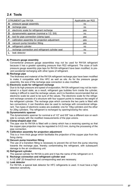
2.4 Tools STRUMENTI per R410A Applicabile per R22 A pressure gauge assembly no B recharge pipe no C electronic scale for refrigerant recharge yes D dynamometric spanner (nominal ø 1/2, 5/8) no E tool for pipe connection (clamp type) yes F calibration assembly for projection adjustment yes G vacuum pump transition fitting yes H refrigerant cylinder no I recharge connection and refrigerant cylinder seal no L leak detector no A) Pressure gauge assembly Conventional pressure gauge assemblies may not be used for R410A refrigerant because it has a greater operating pressure than R22 refrigerant. The sizes of both pressure gauge assembly pipe taps for R410A refrigerant have been modified, to prevent accidental recharging with other types of refrigerant. B) Recharge pipe The thickness and material of the R410A refrigerant recharge pipe have been modified to make it compatible with this HFC as well as oils. As for the pressure gauge assembly, the size of the recharge pipe connection is also modified. C) Electronic scale for refrigerant recharge Due to its high pressure and speed of evaporation, R410A refrigerant may not be maintained in a liquid state; as a result, refrigerant gas bubbles form inside the cylinder, making it difficult to read the recharge values, and it is therefore recommended that an electronic scale be used to be sure of the values. The electronic scale for the refrigerant recharge consists of a structure with four support points to measure the weight of the refrigerant cylinder. The recharge pipe which connects the two parts is fitted with two connections; it can therefore also be used to recharge with conventional refrigerant. Two types of electronic scales are available: one for 10kg cylinders and the other for 20kg cylinders. The refrigerant is recharged by opening/closing the valve. D) Dynamometric spanner The dynamometric spanner for nominal ø of 1/2” and 5/8” has a different size on each side to comply with the modified measurements of the pipe unions. E) Clamp-shaped pipe vice The pipe vice for R410A is fitted with a clamp which has a receiving opening so that the copper pipe projection may be regulated to 0-0,5 mm, during the processing of the pipe connection. F) Calibration assembly for projection adjustment This is a 1mm thick gauge which facilitates the projection of the copper pipe from the fixing clamp. G) Vacuum pump transition fitting The use of a transition fitting is necessary to prevent the oil from the pump returning towards the recharge pipe, thereby contaminating the refrigerant, with subsequent damage to the air conditioning unit. H) Refrigerant cylinder The special cylinder for R410A is pink and it has the name of the refrigerant on it. I) Recharge connection and refrigerant cylinder seal A 1/2 UNF 20 thread/inch and corresponding seal are necessary. L) Leak detector For R410A, a special leak detector for HFC refrigerants is used. It must have a high detection sensitivity. 27
- Page 1 and 2: MANUALE PER L’INSTALLAZIONE clima
- Page 3 and 4: Nel sollevare carichi con gru o par
- Page 5 and 6: ATTENZIONE: - Assicurarsi che l’a
- Page 7 and 8: 1.5 Installazione unità esterna Mo
- Page 9 and 10: 2.5 Spessore dei tubi in rame DIAME
- Page 11 and 12: 2.10 Recupero del refrigerante Proc
- Page 13 and 14: 3.2 SCHEMI ELETTRICI DI COLLEGAMENT
- Page 15 and 16: 24000 Indoor unit: •••••
- Page 17 and 18: 48000 17
- Page 19 and 20: ATTENZIONE - Prima di effettuare qu
- Page 21 and 22: WARNING NORM READ THIS MANUAL FULLY
- Page 23 and 24: 1 INSTALLATION 1.1 Minimum distance
- Page 25: 1.2 Side view 18000 24000/36000/480
- Page 29 and 30: TIGHTENING TORQUE FOR THE FLANGE CO
- Page 31 and 32: 3 ELECTRICAL CONNECTIONS ATTENZIONE
- Page 33 and 34: 18000 Indoor unit: • • •• O
- Page 35 and 36: • • • • • • • • •
- Page 37 and 38: 4 FINAL STAGES ATTENTION: - Use man
- Page 39 and 40: DIMENSIONI/DIMENSIONS UNITA’ INTE
- Page 44: ECOFLAM SpA Treviso - Italy 4200100
2.4 Tools<br />
STRUMENTI per R410A<br />
Applicabile per R22<br />
A pressure gauge assembly no<br />
B recharge pipe no<br />
C electronic scale for refrigerant recharge yes<br />
D dynamometric spanner (nominal ø 1/2, 5/8) no<br />
E tool for pipe connection (clamp type) yes<br />
F calibration assembly for projection adjustment yes<br />
G vacuum pump transition fitting yes<br />
H refrigerant cylinder no<br />
I recharge connection and refrigerant cylinder seal no<br />
L leak detector no<br />
A) Pressure gauge assembly<br />
Conventional pressure gauge assemblies may not be used for R410A refrigerant<br />
because it has a greater operating pressure than R22 refrigerant. The sizes of both<br />
pressure gauge assembly pipe taps for R410A refrigerant have been modified, to prevent<br />
accidental recharging with other types of refrigerant.<br />
B) Recharge pipe<br />
The thickness and material of the R410A refrigerant recharge pipe have been modified<br />
to make it compatible with this HFC as well as oils. As for the pressure gauge<br />
assembly, the size of the recharge pipe connection is also modified.<br />
C) Electronic scale for refrigerant recharge<br />
Due to its high pressure and speed of evaporation, R410A refrigerant may not be maintained<br />
in a liquid state; as a result, refrigerant gas bubbles form inside the cylinder,<br />
making it difficult to read the recharge values, and it is therefore recommended that an<br />
electronic scale be used to be sure of the values. The electronic scale for the refrigerant<br />
recharge consists of a structure with four support points to measure the weight of<br />
the refrigerant cylinder. The recharge pipe which connects the two parts is fitted with<br />
two connections; it can therefore also be used to recharge with conventional refrigerant.<br />
Two types of electronic scales are available: one for 10kg cylinders and the other<br />
for 20kg cylinders. The refrigerant is recharged by opening/closing the valve.<br />
D) Dynamometric spanner<br />
The dynamometric spanner for nominal ø of 1/2” and 5/8” has a different size on each<br />
side to comply with the modified measurements of the pipe unions.<br />
E) Clamp-shaped pipe vice<br />
The pipe vice for R410A is fitted with a clamp which has a receiving opening so that<br />
the copper pipe projection may be regulated to 0-0,5 mm, during the processing of the<br />
pipe connection.<br />
F) Calibration assembly for projection adjustment<br />
This is a 1mm thick gauge which facilitates the projection of the copper pipe from the<br />
fixing clamp.<br />
G) Vacuum pump transition fitting<br />
The use of a transition fitting is necessary to prevent the oil from the pump returning<br />
towards the recharge pipe, thereby contaminating the refrigerant, with subsequent<br />
damage to the air conditioning unit.<br />
H) Refrigerant cylinder<br />
The special cylinder for R410A is pink and it has the name of the refrigerant on it.<br />
I) Recharge connection and refrigerant cylinder seal<br />
A 1/2 UNF 20 thread/inch and corresponding seal are necessary.<br />
L) Leak detector<br />
For R410A, a special leak detector for HFC refrigerants is used. It must have a high<br />
detection sensitivity.<br />
27


