Manuale Installatore - Elco Ecoflam
Manuale Installatore - Elco Ecoflam
Manuale Installatore - Elco Ecoflam

You also want an ePaper? Increase the reach of your titles
YUMPU automatically turns print PDFs into web optimized ePapers that Google loves.
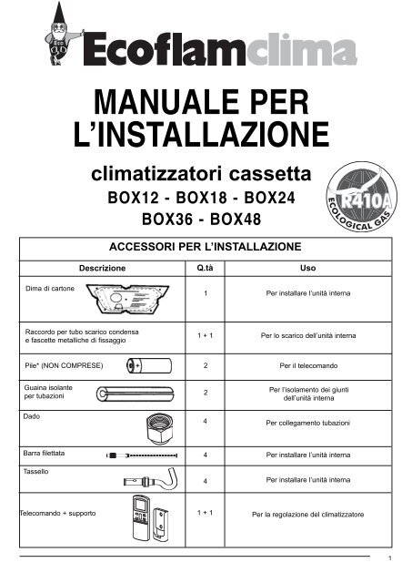
MANUALE PER<br />
L’INSTALLAZIONE<br />
climatizzatori cassetta<br />
BOX12 - BOX18 - BOX24<br />
BOX36 - BOX48<br />
ACCESSORI PER L’INSTALLAZIONE<br />
Descrizione Q.tà Uso<br />
Dima di cartone<br />
1 Per installare l’unità interna<br />
Raccordo per tubo scarico condensa<br />
e fascette metalliche di fissaggio<br />
1 + 1<br />
Per lo scarico dell’unità interna<br />
Pile* (NON COMPRESE)<br />
2<br />
Per il telecomando<br />
Guaina isolante<br />
per tubazioni<br />
Dado<br />
2 Per l’isolamento dei giunti<br />
dell’unità interna<br />
4 Per collegamento tubazioni<br />
Barra filettata<br />
Tassello<br />
4 Per installare l’unità interna<br />
4 Per installare l’unità interna<br />
Telecomando + supporto<br />
1 + 1<br />
Per la regolazione del climatizzatore<br />
1
ATTENZIONE<br />
NORMA<br />
PRIMA DI EFFETTUARE L’INSTALLAZIONE<br />
LEGGERE ATTENTAMENTE E COMPLETAMENTE QUESTO MANUALE<br />
RISCHIO<br />
Assicurarsi che l’ambiente di installazione e gli impianti a cui deve connettersi<br />
l’apparecchiatura siano conformi alle normative vigenti.<br />
Non danneggiare, nel forare la parete, cavi elettrici o tubazioni preesistenti.<br />
Proteggere tubi e cavi di collegamento in modo da evitare il loro danneggiamento.<br />
Adoperare utensili ed attrezzature manuali adeguati all’uso (in particolare<br />
assicurarsi che l’utensile non sia deteriorato e che il manico sia integro e correttamente<br />
fissato), utilizzarli correttamente, assicurarli da eventuale caduta<br />
dall’alto, riporli dopo l’uso.<br />
Adoperare attrezzature elettriche adeguate all’uso (in particolare assicurarsi<br />
che il cavo e la spina di alimentazione siano integri e che le parti dotate di<br />
moto rotativo o alternativo siano correttamente fissate), utilizzarle correttamente,<br />
assicurarle da eventuali caduta dall’alto, scollegare e riporle dopo<br />
l’uso.<br />
Assicurarsi che le scale portatili siano stabilmente appoggiate, che siano<br />
appropriatamente resistenti, che i gradini siano integri e non scivolosi, che<br />
non vengano spostete con qualcuno sopra, che qualcuno vigili.<br />
Assicurarsi che le scale a castello siano stabilmente appoggiate, che siano<br />
appropiatamente resistenti, che i gradini siano integri e non scivolosi, che<br />
abbiano mancorrenti lungo la rampa e parapetti sul pianerottolo.<br />
Assicurarsi, durante i lavori eseguiti in quota (in genere con dislivello superiore<br />
a due metri), che siano adottati parapetti perimetrali nella zona i lavoro<br />
o imbragature individuali atti a prevenire la caduta, che lo spazio percorso<br />
durante l’eventuale caduta sia libero da ostacoli pericolosi, che l’eventuale<br />
impatto sia attutito da superfici di arresto semirigide o deformabili.<br />
Indossare, durante le lavorazioni, gli indumenti e gli equipaggiamenti protettivi<br />
individuali.<br />
Le operazioni all’interno dell’apparecchio devono essere eseguite con la<br />
cautela necessaria ad evitare bruschi contatti con parti accuminate.<br />
Effettuare la ricarica di gas refrigerante attenendosi a quanto specificato<br />
nella scheda di sicurezza del prodotto, indossando indumenti protettivi, evitando<br />
fuoriuscite violente del gas dal serbatoio o dalle connessioni dell’impianto.<br />
Non dirigere il flusso dell’aria verso piani di cottura o stufe a gas.<br />
Non installare l’unità esterna in luoghi ove possa costituire pericolo o intralcio<br />
al passaggio di persone, o possa arrecare disturbo per il rumore o il flusso<br />
d’aria.<br />
Folgorazione per contatto con conduttori<br />
sotto tensione incorrettamente installati.<br />
Folgorazione per contatto con conduttori<br />
sotto tensione.<br />
Esplosioni, incendi o intossicazioni per perdita<br />
gas dalle tubazioni danneggiate.<br />
Folgorazione per contatto con conduttori<br />
sotto tensione.<br />
Ustioni da raffreddamento per fuoriuscita gas<br />
dalle tubatore danneggiate<br />
Lesioni personali per proiezioni di schegge o<br />
frammenti, inalazione polveri, urti, tagli, punture,<br />
abrasioni.<br />
Lesioni personali per folgorazione, proiezione<br />
di schegge o frammenti, inalazione polveri,<br />
urti, tagli, punture, abrasioni, rumore,<br />
vibrazioni.<br />
Lesioni personali per la caduta dall’alto o per<br />
cesoiamento (scale doppie).<br />
Lesioni personali per la caduta dall’alto.<br />
Lesioni personali per urti, inciampi, ferite.<br />
Lesioni personali per folgorazione, proiezione<br />
di schegge o frammenti, inalazioni polveri,<br />
urti, tagli, punture, abrasioni, rumore,<br />
vibrazioni.<br />
Lesioni personali per tagli, punture, abrasioni.<br />
Lesioni personali per ustioni da freddo.<br />
Esplosioni, incendi o intossicazione per<br />
efflusso gas dagli ugelli di alimentazione<br />
fiamme spente dal flusso dell’aria.<br />
Lesioni personali per contusioni, inciampi,<br />
rumore, eccessiva ventilazione.<br />
2
Nel sollevare carichi con gru o paranchi assicurarsi della stabilità e dell’efficienza<br />
dei mezzi di sollevamento in relazione al movimento ed al peso del<br />
carico, imbragare correttamente il carico, applicare delle funi per controllare<br />
le oscillazioni e gli spostamenti laterali, manovrare la salita da una posizione<br />
che consente la visuale di tutta l’area interessata dal percorso, non permettere<br />
la sosta o il passaggio di persone sotto il carico sospeso.<br />
Non dirigere il flusso dell’aria verso piani di cottura o stufe a gas.<br />
Non dirigere il flusso d’aria verso oggetti di valore, piante o animali.<br />
Installare l’apparecchio su parete solida, non soggetta a vibrazioni.<br />
Disporre lo scarico della condensa in modo da consentire da consentire il<br />
corretto deflusso dell’aria verso luoghi ove non possa disturbare o danneggiare<br />
persone, cose o animali.<br />
Non danneggiare, nel forare la parete, cavi elettrici o tubazioni preesistenti.<br />
Eseguire i collegamenti elettrici con conduttori di sezione adeguata.<br />
Assicurarsi che l’ambiente di installazione e gli impianti a cui deve connettersi<br />
l’apparecchiatura siano conformi alle normative vigenti.<br />
Adoperare attrezzature elettriche adeguate all’uso (in particolare assicurarsi<br />
che il cavo e la spina di alimentazione siano integri e che le parti dotate di<br />
moto rotativo o alternativo siano correttamente fissate), utilizzarle correttamente,<br />
assicurarle da eventuali caduta dall’alto, scollegare e riporle dopo<br />
l’uso.<br />
Proteggere con adeguato materiale l’apparecchio e le aree in prossimità del<br />
luogo di lavoro.<br />
Movimentare l’apparecchio con la dovuta cautela.<br />
Organizzare la dislocazione del materiale e delle attrezzature in modo da<br />
rendere agevole e sicura la movimentazione, evitando cataste che possano<br />
essere soggetto e cedimenti o crolli.<br />
Ripristinare tutte le funzioni di sicurezza e controllo interessate da un intervento<br />
sull’apparecchio ed accertarne la funzionalità prima della rimessa in<br />
servizio.<br />
Lesioni personali per caduta oggetti dall’alto.<br />
Danneggiamento dell’appaecchio o di oggetti<br />
circostanti per caduta dall’alto, urti.<br />
Esplosioni, incendi o intossicazion per efflusso<br />
gas dagli ugelli di alimentazione, fiamme<br />
spente dal flusso d’aria.<br />
Danneggiamento o deperimento per eccessivo<br />
freddo/caldo, umidità, ventilazione.<br />
Rumorosità durante il funzionamento.<br />
Danneggiamento oggetti per gocciolamento<br />
acqua.<br />
Danneggiamento impianti preesistenti<br />
Allagamenti per perdita acqua dalle tubazioni<br />
danneggiate.<br />
Incendio per surriscaldamento dovuto al passaggio<br />
di corrente elettrica in cavi sottodimensionati.<br />
Danneggiamento dell’apparecchio per condizioni<br />
di funzionamento improprie.<br />
Danneggiamento dell’apparecchio o di<br />
oggetti circostanti per proiezioni di schegge,<br />
colpi, incisioni.<br />
Danneggiamento dell’apparecchio o di<br />
oggetti circostanti per proiezione di schegge,<br />
colpi, incisioni.<br />
Danneggiamento dell’apparecchio o di<br />
oggetti circostanti per urti, colpi, incisioni,<br />
schiacciamento.<br />
Danneggiamento dell’apparecchio o di<br />
oggetti circostanti per urti, colpi, incisioni,<br />
schiacciamento.<br />
Danneggiamento o blocco dell’apparecchio<br />
per funzionamento fuori controllo.<br />
3
1<br />
INSTALLAZIONE<br />
1.1 Distanze minime<br />
Per una buona installazione rispettare le distanze<br />
minime come mostrato nella figura a fianco e lasciare<br />
gli spazi necessari alla circolazione dell’aria.<br />
Utilizzare gli accessori in dotazione per eseguire<br />
l’installazione a regola d’arte.<br />
MIN<br />
100 cm<br />
MIN<br />
100 cm<br />
Nota:<br />
Le dimensioni delle unità interna ed esterna si trovano<br />
alla fine del manuale<br />
ATTENZIONE:<br />
- Assicurarsi che l’ambiente di installazione e gli<br />
impianti a cui deve connettersi l’apparecchiatura<br />
siano conformi alle normative vigenti.<br />
- Adoperare utensili ed attrezzature manuali adeguati<br />
all’uso (in particolare assicurarsi che l’utensile non<br />
sia deteriorato e che il manico sia integro e correttamente<br />
fissato), utilizzarli correttamente, assicurarli<br />
da eventuale caduta dall’alto, riporli dopo l’uso.<br />
(rischio di lesioni personali per proiezioni di schegge<br />
o frammenti, e danneggiamento dell’apparecchio o<br />
di oggetti circostanti).<br />
- Nel sollevare carichi con gru o paranchi assicurarsi<br />
della stabilità e dell’efficienza dei mezzi di sollevamento<br />
in relazione al movimento ed al peso del carico,<br />
imbragare correttamente il carico, applicare delle<br />
funi per controllare le oscillazioni e gli spostamenti<br />
laterali, manovrare la salita da una posizione che<br />
consente la visuale di tutta l’area interessata dal<br />
percorso, non permettere la sosta o il passaggio di<br />
persone sotto il carico sospeso.<br />
18000 - 24000 - 36000 48000<br />
4
ATTENZIONE:<br />
- Assicurarsi che l’ambiente di installazione e gli impianti a cui deve connettersi l’apparecchiatura<br />
siano conformi alle normative vigenti.<br />
- Adoperare utensili ed attrezzature manuali adeguati all’uso (in particolare assicurarsi che l’utensile<br />
non sia deteriorato e che il manico sia integro e correttamente fissato), utilizzarli correttamente,<br />
assicurarli da eventuale caduta dall’alto, riporli dopo l’uso.<br />
(rischio di lesioni personali per proiezioni di schegge o frammenti, e danneggiamento dell’apparecchio<br />
o di oggetti circostanti).<br />
Scegliere un luogo per l’installazione in maniera tale<br />
che attorno alla macchina, vi siano spazi di almeno<br />
100 cm.<br />
MIN<br />
100 cm<br />
MIN<br />
100 cm<br />
Verificare che l’installazione non interferisca con l’impianto<br />
elettrico o idraulico già esistente.<br />
Determinare la posizione e la dimensione del foro sul<br />
soffitto utilizzando il diametro esterno della dima di<br />
cartone.<br />
Scegliere la posizione finale dell’unità interna nel soffitto<br />
con l’ausilio deei riferimenti “A-B-C-D” stampati<br />
sulla dima di cartone.<br />
Per il fissaggio dell’unità al soffitto, utilizzare della<br />
barra filettata con dei tasselli adeguati.<br />
Assicurarsi, con l’aiuto di una bolla, che l’unità sia<br />
posizionata orizzontalmente ed<br />
adeguatamente bloccata al soffitto.<br />
DADO<br />
FISCHER<br />
STAFFA DI<br />
SOSPENSIONE<br />
Fissare le barre distanziatrici nelle posizioni 1-2-3-4,<br />
seguendo le indicazioni riportate sulla dima in cartone.<br />
NOTE:<br />
· Non piegare o strozzare le tubazioni dell’unità interna. Evitare curve di raggio inferiore ai 10 cm.<br />
· Non curvare troppe volte lo stesso tratto di tubo altrimenti dopo 3 volte rischia di strozzarsi.<br />
· Rimuovere la chiusura dei tubi dell’unità interna solo immediatamente prima di effettuare i collegamenti.<br />
· Al fine di evitare la deformazione dei pannelli laterali, si raccomanda di non stringere eccessivamente le viti in fase di<br />
montaggio.<br />
5
1.2 Vista in pianta<br />
12000/18000 24000/36000/48000<br />
V<br />
(ganci)<br />
(pannello)<br />
(foro)<br />
(ganci)<br />
(corpo)<br />
(pannello)<br />
(foro)<br />
(ganci)<br />
(corpo)<br />
(ganci)<br />
H I L M H I M L U<br />
Q (ganci)<br />
(corpo)<br />
R<br />
S<br />
T<br />
(foro)<br />
(pannello)<br />
Q<br />
R<br />
S<br />
T<br />
(ganci)<br />
(corpo)<br />
(foro)<br />
(pannello)<br />
1.3 Vista laterale<br />
(soffitto)<br />
(corpo)<br />
(scarico cond.)<br />
(tubi)<br />
(ganci)<br />
C<br />
F E D<br />
B<br />
A<br />
(corpo)<br />
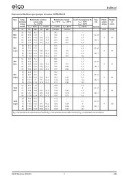
DIMENSIONI UNITA’ INTERNA (in mm)<br />
BTU/h A B C D E F H I L M Q R S T U V<br />
12000 600 160 289 135 210 265 650 611 600 580 401 580 600 650 - -<br />
18000 600 160 289 135 210 265 650 611 600 580 401 580 600 650 - -<br />
24000 880 130 260 135 190 230 950 880 785 840 679 840 880 950 778 690<br />
36000 880 130 330 140 200 310 950 880 785 840 679 840 880 950 778 690<br />
48000 880 130 330 140 200 310 950 880 785 840 679 840 880 950 778 690<br />
1.4 Utilizzo Canalizzato<br />
L’unità interna del modello a cassetta permette, grazie<br />
alle apposite aperture mostrate in figura, l’utilizzo della<br />
macchina come un modello canalizzato.<br />
Questa modalità di installazione può essere molto utile<br />
nel caso si volessero climatizzare più ambienti con<br />
un’unica unità.<br />
6
1.5 Installazione unità esterna<br />
Montare l’unità esterna su una parete solida e in modo molto sicuro.<br />
Attenersi alla procedura descritta e iniziare i collegamenti delle tubazioni e dei cavi elettrici:<br />
· stabilire la posizione idonea sulla parete, prevedendo gli spazi necessari per poter effettuare agevolmente<br />
eventuali interventi di manutenzione;<br />
· fissare la staffa (non inclusa) alla parete utilizzando dei tasselli adatti al tipo di muro;<br />
· usare tasselli in quantità maggiore rispetto al peso che devono sostenere: durante il funzionamento<br />
la macchina vibra e dovrà rimanere installata per anni senza che le viti si allentino.<br />
2<br />
TUBAZIONI E COLLEGAMENTI<br />
ATTENZIONE:<br />
- non bere l’acqua di condensa (lesioni personali per intossicazione)<br />
- Disporre lo scarico della condensa in modo da consentire il corretto defluire dell’acqua in luoghi<br />
appositamente dedicati, in modo da non disturbare o danneggiare persone, cose, animali,<br />
piante e strutture.<br />
- Adoperare utensili ed attrezzature manuali adeguati all’uso (in particolare assicurarsi che l’utensile<br />
non sia deteriorato e che il manico sia integro e correttamente fissato), utilizzarli correttamente,<br />
assicurarli da eventuale caduta dall’alto, riporli dopo l’uso. (Lesioni personali per<br />
proiezioni di schegge o frammenti, inalazione polveri, urti, tagli, punture, abrasioni)<br />
2.1 Collegamento delle tubazioni frigorifere<br />
tubazione<br />
frigorifera<br />
cavo di<br />
potenza<br />
cavo dei<br />
segnali<br />
tubo di scarico<br />
per la condensa<br />
guaina isolante<br />
isolamento<br />
tubazioni<br />
tubazione<br />
frigorifera<br />
Girare i tubi nella direzione del foro nel muro con attenzione a non strozzarli,<br />
e unire i tubi di rame, il tubo di scarico per la condensa e i cavi elettrici con un<br />
nastro isolante, mantenendo il tubo di scarico della condensa più in basso<br />
possibile in modo che l’acqua possa scorrere liberamente.<br />
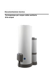
2.2 Scarico della condensa dall’unità interna<br />
Lo scarico della condensa dell’unità interna è un punto<br />
fondamentale per la buona riuscita dell’installazione.<br />
1. Mantenere il tubo per la condensa sulla parte bassa<br />
del foro nel muro.<br />
2. L’isolante dei tubi in rame deve avere almeno 6 mm di<br />
spessore.<br />
Collegamento tubo di scarico:<br />
- L'unità è equipaggiata con una pompa anti-condensa<br />
con un'aspirazione di 300 mm.<br />
- collegare il tubo di scarico condensa all'uscita posta<br />
sul lato dell'unità<br />
- il tubo di scarico deve avere una pendenza del 2%<br />
N.B.<br />
Praticare un foro nel muro che sia, dalla parte esterna di<br />
5-10 mm più basso che all’interno in modo che la pendenza<br />
favorisca il deflusso della condensa.<br />
2.3 Scarico della condensa dall’unità esterna<br />
La condensa o l’acqua, che si formano nell’unità esterna durante il funzionamento<br />
in riscaldamento, possono essere eliminate attraverso il raccordo<br />
di scarico.<br />
Installazione: fissare il raccordo di scarico nel foro da 25 mm che si trova sul<br />
fondo dell’unità, come mostrato nel disegno a fianco.<br />
Collegare il tubo per lo scarico della condensa con il raccordo e fare in<br />
modo che l’acqua finisca in uno scarico adatto.<br />
interno<br />
esterno<br />
5 mm<br />
7
2.4 Strumenti<br />
STRUMENTI per R410A<br />
Applicabile per R22<br />
A gruppo manometri no<br />
B tubo di carica no<br />
C bilancia elettronica per carica refrigerante sì<br />
D chiave dinamometrica (ø nominale 1/2, 5/8) no<br />
E attrezzo per cartella (tipo a pinza) sì<br />
F gruppo calibro per aggiustamento di proiezione sì<br />
G adattatore della pompa del vuoto sì<br />
H bombola refrigerante no<br />
I attacco di carica e guarnizione della bombola refrigerante no<br />
L cercafughe no<br />
A) Gruppo manometri<br />
I gruppi manometri convenzionali non possono essere utilizzati per il refrigerante<br />
R410A in quanto esso ha una pressione di funzionamento maggiore rispetto al refrigerante<br />
R22. Entrabe le prese del gruppo manometri per refrigerante R410A sono<br />
state modificate nelle dimensioni, in modo da evitare carichi accidentali con altri tipi di<br />
refrigerante.<br />
B) Tubo di carica<br />
Il tubo di carica per refrigerante R410A è stato modificato di spessore e materiale per<br />
renderlo più compatibile con questo HFC e gli oli. Come per il gruppo manometri,<br />
anche nel tubo di carica sono variate le dimensione dell’attacco.<br />
C) Bilancia elettronica per carica refrigerante<br />
Il refrigerante R410A a causa della sua alta pressione e velocità di evaporazione non<br />
può essere mantenuto allo stato liquido, così all’interno del cilindro si formano bolle di<br />
refrigerante gassoso , questo rende difficile leggere i valori di carica, quindi è consigliabile<br />
uilizzare una bilancia elettronica per essere sicuri dei valori. La bilancia elettonica<br />
per la carica di refrigerante ha una struttura con quattro punti di supporto per la<br />
rilevazione del peso del cilindro di refrigerante. Il tubo di carica che collega le due parti<br />
dispone di due attacchi, esso quindi può essere utilizzato anche per la carica di refrigerante<br />
convenzionale. Sono disponibili due tipi di bilance elettroniche: una per cilindro<br />
da 10kg e l’altra per cilindro da 20kg. La carica del refrigerante si effettua aprendo/chiudendo<br />
la valvola.<br />
D) Chiave dinamometrica<br />
La chiave dinamometrica per ø nominali di 1/2” e 5/8” , ha dimensioni diverse su<br />
entrambi i lati per rispondere alle misure modificate dei bocchettoni a cartella.<br />
E) Cartellatrice a pinza<br />
La cartellatrice a pinza per R410A è dotata di un morsetto con foro ricevitore in modo<br />
che la proiezione del tubo di rame possa essere regolata a 0-0,5 mm, nella lavorazione<br />
della cartella.<br />
F) Gruppo calibro per aggiustamento di proiezione<br />
Si tratta di un calibro dallo spessore di 1 mm che agevola la proiezione del tubo di rame<br />
dal morsetto di fisaggio.<br />
G) Adattatore della pompa del vuoto<br />
L’uso di un adattatore è necessario per prevenire che l’olio dalla pompa per il vuoto<br />
ritorni verso il tubo di carica, inquinando il refrigerante con conseguenti danni al climatizzatore.<br />
H) Bombola refrigerante<br />
La bombola esclusiva per l’R410A è di colore rosa ed è contrassegnata dal nome del<br />
refrigerante.<br />
I) Attacco di carica e guarnizione della bombola refrigerante<br />
Risulta necessario un attacco di carica da 1/2 UNF 20 filetti/pollice e guarnizione corrispondente.<br />
L) Cercafughe<br />
Per l’R410A si utilizza un cercafughe esclusivo per i refrigeranti HFC. Esso deve avere<br />
un’alta sensibilità di rilevazione .<br />
8
2.5 Spessore dei tubi in rame<br />
DIAMETRO NOMINALE DIAMETRO ESTERNO SPESSORE<br />
(pollici) (mm) (mm)<br />
1/4 6,35 0,8<br />
3/8 9,52 0,8<br />
1/2 12,70 0,8<br />
5/8 15,88 1,0<br />
Nei climatizzatori di tipo split funzionanti con refrigerante R410A si utilizza<br />
una valvola a tre vie dell’unità esterna con valvola a spillo di diametro diverso<br />
dalle macchine per refrigerante R22 in modo da evitare che le unità vengano<br />
caricate accidentalmente con un altro tipo di refrigerante.<br />
Inoltre, per aumentare la resistenza alla pressione, per i tubi di rame con diametro<br />
nominale di 1/2” e 5/8” sono state cambiate le dimensioni esecutive<br />
della cartella e la misura dei bocchettoni a cartella sul lato opposto.<br />
2.6 Come collegare i tubi<br />
· Rimuovere la chiusura dei tubi solo appena prima di effettuare il collegamento:<br />
si deve assolutamente evitare che entri umidità o sporcizia.<br />
· Se un tubo viene curvato troppe volte, diventa duro: non curvarlo più di 3<br />
volte nello stesso tratto. Svolgere il tubo srotolandolo senza tirare, come<br />
mostrato in figura.<br />
· L’isolante dei tubi in rame deve avere almeno 6 mm di spessore.<br />
2.7 Connessioni all’unità interna<br />
1. Sagomare i tubi di collegamento secondo il tracciato.<br />
2. Togliere la calottina di chiusura dei tubi dell’unità interna (verificare che<br />
all’interno non siano rimaste impurità).<br />
3. Inserire il bocchettone e praticare la flangia all’estremità del tubo di collegamento,<br />
seguendo le indicazioni della tabella:<br />
ø ø mm QUOTA “A” mm CARTELLATRICE<br />
NOMINALE ESTERNO SPESSORE CARTELLATRICE CONVEZIONALE<br />
per R410 a pinza a pinza a farfalla<br />
1/4 6,35 0,8 0-0,5 1,0-1,5 1,5-2,0<br />
3/8 9,52 0,8 0-0,5 1,0-1,5 1,5-2,0<br />
1/2 12,70 0,8 0-0,5 1,0-1,5 2,0-2,5<br />
5/8 15,88 1,0 0-0,5 1,0-1,5 2,0-2,5<br />
SI<br />
NO<br />
chiave dinamometrica<br />
4. Collegare i tubi usando due chiavi, facendo attenzione a non danneggiare<br />
i tubi. Se la forza di serraggio è insufficiente, vi saranno probabilmente delle<br />
perdite. Anche se la forza è eccessiva potranno esserci delle perdite poiché<br />
è facile danneggiare la flangia. Il sistema più sicuro consiste nel serrare<br />
la connessione utilizzando una chiave fissa e una chiave dinamometrica:<br />
in questo caso utilizzare la tabella “coppie di serraggio per le connessioni<br />
a flangia”.<br />
5. Si consiglia di lasciare 50 cm di tubo in rame, per eventuali successivi<br />
interventi in prossimità dei rubinetti<br />
2.8 Connessioni all’unità esterna<br />
Avvitare i bocchettoni agli attacchi dell’unità esterna con lo stesso serraggio<br />
descritto per l’unità interna.<br />
Per evitare perdite porre particolare attenzione ai seguenti punti:<br />
· Stringere i bocchettoni facendo attenzione a non danneggiare i tubi.<br />
· Se la forza di serraggio è insufficiente, vi saranno probabilmente delle perdite.<br />
Anche se la forza è eccessiva potranno esserci delle perdite poiché è<br />
facile danneggiare la flangia.<br />
· Il sistema più sicuro consiste nel serrare la connessione utilizzando una chiave<br />
dinamometrica: in questo caso utilizzare le seguenti tabella.<br />
bocchettoni<br />
rubinetto<br />
del liquido<br />
tubi di collegamento<br />
45°~ 46°<br />
B<br />
A<br />
43°~ 45°<br />
rubinetto del gas<br />
C<br />
D<br />
9
COPPIE DI SERRAGGIO PER LE CONNESSIONI A FLANGIA<br />
Tubo Coppia di serraggio Sforzo corrispondente<br />
[Kg x cm]<br />
(usando una chiave di 20 cm)<br />
6,35 mm ( 1 / 4” ) 140-180 forza del polso<br />
9,52 mm ( 3 / 8” ) 330-420 forza del braccio<br />
12,70 mm ( 1 / 2” ) 500 - 620 forza del braccio<br />
15.88 mm ( 5 / 8” ) 630 - 770 forza del braccio<br />
COPPIE DI SERRAGGIO PER TAPPI DI PROTEZIONE<br />
Coppia di serraggio (Kg x cm)<br />
Attacco di servizio 70 - 90<br />
Tappi di protezione 250 - 300<br />
Lunghezza delle tubazioni<br />
La lunghezza massima per la tubazione di collegamento e di 20 m . Quando<br />
si hanno lunghezze superiore ai 4 m, fare attenzione alla quantità di refrigerante<br />
da aggiungere per ogni metro. Nel caso si debba installare l’unità esterna<br />
più in alto dell’unità interna con un dislivello verticale superiore ai 3 m, si<br />
deve ricorrere a dei sifoni sulle tubazioni di ritorno, in modo che l’olio che cola<br />
sulle pareti si deposita nel sifone fino al suo riempimento. Il tappo d’olio che<br />
si è formato verrà sparato in alto dal gas.<br />
max 10m<br />
≥3m<br />
2.9 Fare il vuoto e verificare la tenuta<br />
Lo spurgo dell’aria dal circuito deve avvenire per mezzo di una pompa per il<br />
vuoto, l’adattatore della pompa ed il gruppo manometri adatti all’ R410A.<br />
Accertarsi che la pompa del vuoto sia piena d’olio fino al livello indicato dalla<br />
spia dell’olio.<br />
pompa<br />
del vuoto<br />
Collegare la pompa a vuoto all’attacco di servizio, dopo aver verificato che i<br />
due rubinetti sull’unità esterna siano chiusi.<br />
1. svitare i tappi dei rubinetti delle valvole a 2 e 3 vie, e alla valvola di servizio,<br />
2. collegare la pompa del vuoto alla valvolina di servizio posta nella valvola a<br />
3 vie dell’unità esterna e all’adattatore della pompa del vuoto,<br />
3. dopo aver aperto le opportune valvole della pompa, avviarla e lasciarla funzionare.<br />
Fare il vuoto per circa 20/25 minuti,<br />
4. verificare che il manometro di sinistra si sia spostata verso -76 cm Hg (vuoto<br />
di 4 mm Hg o meno),<br />
5. chiudere i rubinetti della pompa e spegnerla. Verificare che l’ago del manometro<br />
non si sposti per circa 5 minuti. Se l’ago si sposta vuol dire che ci sono<br />
infiltrazioni d’aria nell’impianto, bisogna quindi controllare tuti i serraggi e l’esecuzione<br />
delle cartelle a questo punto ripetere la procedura dal punto 3,<br />
6. scollegare la pompa del vuoto,<br />
7. aprire completamente i rubinetti delle valvole a 2 e 3 vie,<br />
8. avvitare strettamente a tenuta il tappo sulla presa di servizio,<br />
9. dopo aver stretto tutti i tappi verificare sulla loro circonferenza che non vi rubinetto<br />
siano perdite di gas.<br />
attacco di servizio<br />
unità interna<br />
valvola del gas<br />
tappi di<br />
protezione<br />
attacco di<br />
servizio<br />
valvola<br />
del liquido<br />
rubinetto<br />
ATTENZIONE<br />
Proteggere sempre tubi e cavi di collegamento in modo da evitare il loro<br />
danneggiamento, in quanto una volta danneggiati potrebbero causare una<br />
fuoriuscita del gas. (lesioni personali per ustioni da freddo)<br />
10
2.10 Recupero del refrigerante<br />
Procedura per riportare tutto il refrigerante nell’unità esterna.<br />
1. svitare i tappi dei rubinetti delle valvole a 2 e 3 vie.<br />
2. impostare l’apparecchio in modalità raffreddamento (controllare se il compressore funziona) e lasciare<br />
in funzione per qualche minuto.<br />
3. collegare il manometro<br />
4. chiudere la valvola a 2 vie<br />
5. quando il manometro indica lo “0” chiudere la valvola a 3 vie e spegnere subito il condizionatore<br />
6. chiudere i tappi delle valvole<br />
MODELLO 18000 24000 36000 48000<br />
Diametro tubo del liquido 1/4” 3/8” 1/2” 1/2”<br />
Diametro tubo del gas 1/2” 5/8” 3/4” 3/4”<br />
Massima lunghezza del tubo con carica standard 5 m 5 m 5 m 5 m<br />
Massima distanza tra unità interna ed esterna* 30 m 30 m 30 m 30 m<br />
Carica supplementare del gas 30 g/m 65 g/m 90 g/m 90 g/m<br />
Massimo dislivello tra unità interna ed esterna** 20 m 20 m 20 m 20 m<br />
Tipo di refrigerante R410A R410A R410A R410A<br />
(*) alla distanza massima il rendimento è di circa il 90%.<br />
(**) con dislivello superiore a 3 m è consigliato prevedere un sifone come mostrato in figura<br />
ATTENZIONE:<br />
Effettuare l’eventuale ricarica di gas refrigerante attenendosi a quanto specificato dal prodotto usato,<br />
indossando indumenti protettivi evitando violente fuoriuscite del gas dal serbatoio o dalle connessioni<br />
dell’impianto.<br />
IMPORTANTE CONTROLLO FUGHE DI REFRIGERANTE<br />
Dopo aver eseguito le connessioni aprire i rubinetti in modo che il gas riempa le tubazioni e controllarle<br />
sempre con un cerca fughe le eventuali perdite. (lesioni personali per ustioni da freddo)<br />
2.11 Carica del gas refrigerante<br />
Prima di procedere con la carica di refrigerante, verificare che tutte le valvole e i rubinetti siano chiusi.<br />
NB per la prima installazione eseguire la procedura del paragrafo 2.9 “fare il vuoto e verificare la<br />
tenuta”.<br />
1. Collegare sula bassa pressione del manometro la valvola di srvizio, e collegare il contenitore di refrigerante<br />
alla presa centrale del manometro. Aprire il contenitore del refrigerane quindi aprire il tappo della valvola<br />
centrale e agire sulla valvola a spillo fino a quando non si sente fuoriuscire il refrigerante, quindi rilasciare<br />
lo spillo e riavvitare il tappo.<br />
2. Aprire la valvola a 3 vie e quella a 2 vie<br />
3. Accendere il condizionatore in modalità reffreddamento. Lasciarlo funzionare per qualche minuto.<br />
4. Controllare la pressione indicata dal manometro.<br />
5. Aprire la manopola “LOW”, far fluire il refrigerante gradatamente.<br />
6. Raggiunta la pressione chiudere la manopola “LOW”.<br />
7. Completata la carica, eseguire la prova di funzionamento misurando la temperatura del tubo del gas,<br />
con l’apposito termometro, la temperatura deve essere compresa tra i 5° e 8°C in più della temperatura<br />
letta sul manometro, in corrispondenza della temperatura di evaporazione. Eseguire ora la prova di<br />
tenuta della pressione collegando il gruppo manometrico alla valvola di servizio a 3 vie. Aprire comlpetamente<br />
le valvole a 2 e 3 vie, accendere il condizionatore e con il cercafughe verificare che non ci siano<br />
perdite di refrigerante. (se si verificassero delle perdite eseguire la procedura del paragrafo 2.10 “recupero<br />
del refrigerante”.)<br />
8. Staccare il manometro dalla valvola e spegenre il condizionatore.<br />
9. Staccare il contenitore dal manometro e richiudere tutti i tappi.<br />
11
3<br />
COLLEGAMENTO ELETTRICI<br />
ATTENZIONE:<br />
- Prima di effettuare qualsiasi collegamentro elettrico assicurarsi che sia stata tolta l’alimentazione elettrica dalle unità<br />
- che gli impianti a cui deve connettersi l’apparecchiatura siano conformi alle normative vigenti.<br />
- Utilizzare solo cavi in dotazione o in caso di sostituzione per danneggiamento, utilizzare solo cavi di sezione adeguata.<br />
- Lasciare della lunghezza extra ai cavi di collegamento, per permettere la manutenzione in futuro.<br />
- Non collegare mai il cavo di alimentazione tagliandolo a metà, ciò potrebbe causare una fiammata.<br />
3.1 COLLEGAMENTO UNITÀ ESTERNA<br />
1. Togliere il coperchio della morsettiera.<br />
2. Collegare il connettore del cavo dei segnali (presente solo nelle<br />
versioni pompa di calore)<br />
3. Collegare i fili del cavo di potenza alla morsettiera utilizzando<br />
la stessa numerazione usata all’unità interna.<br />
4. Fissare i cavi con il ferma-cavi.<br />
5. Rimettere il coperchio.<br />
unità esterna<br />
cavo di potenza<br />
ferma-cavo<br />
coperchio<br />
cavo sonda<br />
NOTA: sguainare entrambe le estremità dei fili di collegamento del cavo di alimentazione<br />
come indicato in figura. Fare attenzione a non far entrare in contatto<br />
i fili di collegamento con le tubazioni o altre parti metalliche.<br />
70 mm<br />
15 mm<br />
12
3.2 SCHEMI ELETTRICI DI COLLEGAMENTO:<br />
12000<br />
13
18000<br />
Indoor unit:<br />
••<br />
••<br />
Outdoor unit:<br />
14
24000<br />
Indoor unit:<br />
••••••••••<br />
••••••••••<br />
••••••••••••••<br />
Outdoor unit:<br />
15
• • •<br />
•<br />
•<br />
•<br />
•<br />
•<br />
•<br />
•<br />
•<br />
36000<br />
Indoor unit:<br />
• • • • • • •<br />
• • • • • • • • • •<br />
• • • • • • • •<br />
• • • • • • • • • •<br />
• • • •<br />
• • • • • • •<br />
Outdoor unit:<br />
16
48000<br />
17
4<br />
FASI CONCLUSIVE<br />
ATTENZIONE:<br />
- Adoperare utensili ed attrezzature manuali adeguati all’uso (in particolare assicurarsi<br />
che l’utensile non sia deteriorato e che il manico sia integro e correttamente<br />
fissato), utilizzarli correttamente, assicurarli da eventuale caduta dall’alto,<br />
riporli dopo l’uso. (Lesioni personali per proiezioni di schegge o frammenti,<br />
inalazione polveri, urti, tagli, punture, abrasioni)<br />
- proteggere sempre tubi e cavi di collegamento in moda da evitare il loro<br />
danneggiamento, in quanto una volta danneggiati potrebbero causare<br />
una fuoriuscita del gas. (Lesioni personali per ustioni da freddo.).<br />
- Effettuare la ricarica di gas refrigerante attenendosi a quanto specificato nella<br />
scheda di sicurezza del prodotto, indossando indumenti protettivi, evitando fuoriuscite<br />
violente del gas dal serbatoio o dalle connessioni dell’impianto. (Lesioni<br />
personali per ustioni da freddo).<br />
isolante termico<br />
tubazioni<br />
tubazioni<br />
nastro isolante<br />
fascette<br />
1. Avvolgere un po’ di isolante termico attorno alle giunzioni dell’unità interna e<br />
fissarlo con del nastro isolante.<br />
2. Fissare la parte eccedente del cavo dei segnali alle tubazioni o all’unità esterna.<br />
3. Fissare le tubazioni alla parete (dopo averle rivestite con nastro isolante)<br />
usando delle fascette oppure inserirle in canaline di plastica.<br />
4. Sigillare il foro nel muro attraverso il quale passano le tubazioni in modo che non<br />
possano filtrare acqua o aria.<br />
5. All’esterno isolare tutte le tubazioni scoperte, valvole incluse.<br />
6. Se le tubazioni devono venire fatte passare sopra il soffitto o per un luogo umido e<br />
caldo, avvolgere su di esse addizionale isolante termico del tipo disponibile in commercio<br />
così da evitare la formazione di condensa.<br />
manicotto<br />
(interno)<br />
muro<br />
(esterno)<br />
guarnizione<br />
4.1 COLLAUDO<br />
Controllare i seguenti punti:<br />
- UNITA’ INTERNA<br />
1. I tasti ON/OFF e FAN funzionano regolarmente?<br />
2. Il tasto MODE funziona regolarmente?<br />
3. I tasti per l’impostazione del set point e del TIMER funzionano correttamente?<br />
4. Si accendono tutte le spie?<br />
5. Le alette per l’orientamento dell’aria emessa sono efficienti?<br />
6. La condensa viene scaricata regolarmente?<br />
- UNITA’ ESTERNA<br />
1. Vi sono rumori o vibrazioni durante il funzionamento?<br />
2. Il rumore, il flusso dell’aria o lo scarico della condensa possono recare<br />
disturbo ai vicini?<br />
3. Vi sono perdite di refrigerante?<br />
NOTA: Il controllo elettronico dà il consenso per l’avviamento del compressore<br />
solo tre minuti dopo che è stata data tensione.<br />
18
ATTENZIONE<br />
- Prima di effettuare qualsiasi intervento assicurarsi che sia stata tolta l’alimentazione elettrica dalle unità<br />
- Assicurarsi che gli impianti a cui deve connettersi l’apparecchiatura siano conformi alle normative vigenti.<br />
VERIFICHE SENZA USO DI STRUMENTI<br />
Funzionamento nella modalità Raffreddamento - Verifiche visive sull’Unità Interna<br />
Sintomo<br />
Controllare<br />
Intervento<br />
1 - Si forma della brina sullo scambiatore<br />
dell'Unità Interna.<br />
2 - Non vi è produzione di condensa.<br />
3 - Il compressore funziona ma c'è<br />
poco raffreddamento.<br />
4 - La temperatura dell'aria è bassa,<br />
ma vi è poco raffreddamento.<br />
5 - Il compressore rimane fermo.<br />
6 - La macchina si arresta dopo alcuni<br />
minuti di funzionamento.<br />
1.A - Brina solo sulla parte bassa dello<br />
scambiatore: perdita di gas.<br />
1.B - Brina su tutto lo scambiatore: il filtro<br />
dell'aria è intasato.<br />
La temperatura ambiente è bassa<br />
(< 20° C).<br />
2.A - Se lo scambiatore dell'Unità Interna<br />
rimane asciutto e l'assorbimento di corrente<br />
elettrica è molto minore del nominale<br />
allora vi è una perdita.<br />
3.A - Lo scambiatore di calore dell'Unità<br />
Esterna è intasato o coperto: non vi è un<br />
buono scambio termico.<br />
3.B - Le alette dello scambiatore di calore<br />
dell'Unità Esterna sono piegate.<br />
4.A - Il filtro dell'Unità Interna è intasato.<br />
4.B - L'aria ricircola nell'Unità Interna.<br />
4.C - Dimensionamento della macchina<br />
non adeguato o sovraccarico (p. es.: fonti<br />
di calore, sovraffollamento,...).<br />
5.A - Il compressore è molto caldo: protezione<br />
termica.<br />
6.A - Il ventilatore dell’unità interna è guasto.<br />
RICERCA DEI GUASTI - Parte elettrica -<br />
· Ricercare la perdita e ricaricare.<br />
· Pulire il filtro dell'aria.<br />
Staccare la spina e disinserire l’interrutore<br />
dedicato prima di effettuare<br />
operazioni di pulizia. (rischio di folgora<br />
zione)<br />
· Verificare la temp. amb.<br />
· Individuare la perdita<br />
· sostituire lo scambiatore<br />
· Ripulire lo scambiatore dell'Unità<br />
Esterna.<br />
· Raddrizzare le alette dello<br />
scambiatore esterno.<br />
· Pulire il filtro.<br />
· Favorire la libera circolazione<br />
dell'aria.<br />
· Sostituire la macchina o eliminare<br />
il sovraccarico.<br />
· Attendere che scenda la<br />
temperatura.<br />
· Sostituire il motore.<br />
· Utilizzare solo pezzi originali.<br />
Sintomo<br />
1 - Non dà segno di vita (nessuna<br />
spia, né bip), nemmeno premendo il<br />
tasto AUTO (o TEST) sull'Unità<br />
Interna.<br />
2 - Il telecomando non funziona<br />
oppure funziona solo da vicino.<br />
Controllare<br />
1.A - Controllare se c’é la corrente in rete.<br />
1.B - Controllare se la spina é inserita<br />
bene nella presa a muro.<br />
1.C - Controllare se é saltato l’interruttore<br />
automatico.<br />
1.D - Verificare che il selettore non sia<br />
posizionato sulla funzione stop<br />
2.A - Controllare se le batterie del telecomando<br />
sono cariche<br />
2.B - Controllare che non ci siano ostacoli<br />
(tende o soprammobili) tra il telecomando<br />
e il climatizzatore.<br />
2.C - Verificare che la distanza del climatizzatore<br />
non sia troppo elevata.<br />
DIAGNOSTICA<br />
Intervento<br />
· Ripristinare l'alimentazione e i<br />
collegamenti corretti.<br />
· Inserire correttamente la spina<br />
· Ripristinare l’interruttore<br />
automatico.<br />
· Posizionare il selettore su di<br />
un’altra funzione<br />
· Sostituire le batterie.<br />
· Spostare gli eventuali oggetti.<br />
· Avvicinarsi al climatizzatore.<br />
protezione o malfunzionamento led operation led timer led defrosting led allarme livello condensa auto recover<br />
sensore temperatura interna x o x x si<br />
sensore scambiatore di calore interno o x x x si<br />
sensore scambiatore di calore esterno x x o x si<br />
temperatura della pompa d'acqua o x x o si<br />
unità esterna o o o o si<br />
EEPROM o o x x no<br />
allarme livello condensa x x x o si o no<br />
19
INSTALLATION<br />
MANUAL<br />
cassette-type air conditioning<br />
18000 - 24000 - 36000 - 48000 BTU/h<br />
INSTALLATION ACCESSORIES<br />
Descrizione Q.tà Uso<br />
Cardboard<br />
template<br />
1<br />
To install the internal unit<br />
Fitting for condensed water drain hose and<br />
metal hose clips<br />
1 + 2<br />
For indoor unit drainage<br />
Batteries<br />
2<br />
For the remote control<br />
Insulating sheath<br />
for piping<br />
2<br />
To empty the external unit of condensation<br />
4<br />
4<br />
4<br />
Remote control<br />
1 + 1<br />
For the air conditioning unit settings<br />
20
WARNING<br />
NORM<br />
READ THIS MANUAL FULLY AND CAREFULLY<br />
BEFORE INSTALLING THE APPLIANCE<br />
RISK<br />
Make sure the installation site and any systems to which the appliance must<br />
be connected comply with the applicable norms in force.<br />
When piercing the wall for installation, take care not to damage any electrical<br />
wiring or existing piping.<br />
Electrocution from contact with live conductors<br />
installed incorrectly.<br />
Electrocution from contact with live wires.<br />
Explosions, fires or intoxication from the discharge<br />
of gas leaking from damaged piping.<br />
Protect all connection pipes and cables in order to prevent their being damaged.<br />
Electrocution from contact with live wires.<br />
Cold burns due to gas leaking from damaged<br />
piping.<br />
Use manual tools and equipment suitable for the intended use (in particular,<br />
make sure that the tool is not worn and that the handle is intact and fully<br />
fastened to the rest of the tool); use them correctly and make sure they don’t<br />
fall from a height. Put them safely back in place after use.<br />
Use electrical equipment suitable for the intended use (in particular, make<br />
sure that the power supply cable and plug are intact and that the parts featuring<br />
rotary or reciprocating motion are fastened correctly); use this equipment<br />
correctly; make sure no equipment could fall from a height. Disconnect<br />
it and put it safely back in place after use.<br />
Make sure any portable ladders are positioned securely, and that they are<br />
suitably resistant and that the steps are intact and not slippery and do not<br />
slide around when someone climbs them and ensure someone supervises<br />
at all times.<br />
Make sure any rolling ladders are positioned securely, that they are suitably<br />
resistant, that the steps are intact and not slippery, that the ladders are fitted<br />
with handrails on either side of the ladder and parapets on the landing.<br />
During all work carried out at a certain height (generally with a difference in<br />
height of more than two metres), make sure that parapets are used to surround<br />
the works area or individual harnesses designed to prevent falls, and<br />
that the space covered during any accidental fall is free from dangerous<br />
obstacles, and that any impact upon falling is cushioned by semi-rigid or<br />
deformable surfaces.<br />
During all work, wear individual protective clothing and equipment.<br />
All operations on the inside of the appliance must be performed with the<br />
necessary caution in order to avoid sudden contact with the sharp parts.<br />
Recharge the refrigerant gas in accordance with the instructions provided on<br />
the product safety data sheet, wearing protective clothing, avoiding violent<br />
outlets of gas from the tank or from the system’s connections.<br />
Personal injury from the falling splinters or<br />
fragments, inhalation of dust, shocks, cuts,<br />
pricks and abrasions.<br />
Personal injury from electrocution, falling<br />
splinters or fragments, inhalation of dust,<br />
shocks, cuts, pricks, abrasions, noise and<br />
vibration.<br />
Personal injury from falling from a height or<br />
from cuts (stepladders shutting accidentally).<br />
Personal injury from falling from a height.<br />
Personal injury due to knocks, stumbling and<br />
wounds.<br />
Personal injury from electrocution, falling<br />
splinters or fragments, inhalation of dust,<br />
shocks, cuts, pricks, abrasions, noise and<br />
vibration.<br />
Personal injury from cuts, pricks and abrasions.<br />
Personal injury from cold burns.<br />
Do not direct the air flow towards gas hobs or gas stoves.<br />
Do not install the external unit in places where it could constitute a risk or an<br />
obstruction to the passing of people, or where it could disturb people due to<br />
the noise it makes or the air flow.<br />
Explosions, fires or intoxication from the discharge<br />
of gas leaking from the burner nozzle<br />
once the air flow has put the flame out.<br />
Personal injury from contusions, stumbling,<br />
noise and excessive ventilation.<br />
21
When lifting loads with a crane or hoist, make sure the equipment used for<br />
lifting is stable and efficient and suitably sized for the movement and weight<br />
of the load itself; place the load correctly in slings, tie ropes around it to limit<br />
any oscillations and lateral movements; lift the load from a position where<br />
there is a full view of all the space covered by the load during lifting; do not<br />
allow people to pass or stop in the vicinity of the suspended load.<br />
Do not direct the air flow towards gas hobs or gas stoves.<br />
Do not direct the air flow towards valuable articles, plants or animals.<br />
Install the appliance on a solid wall that is not subjected to any vibrations.<br />
Place the condensation drain pipe in such a way as to ensure the correct<br />
flow of water towards places where it cannot disturb or damage people,<br />
things or animals.<br />
When piercing the wall for installation, take care not to damage any electrical<br />
wiring or existing piping.<br />
Make all electrical connections using conductors with a suitable section.<br />
Personal injury from objects falling from a<br />
height.<br />
Damage to the appliance or surrounding<br />
objects due to the appliance falling from a<br />
height, knocks.<br />
Explosions, fires or intoxication from the discharge<br />
of gas leaking from the burner nozzle<br />
once the air flow has put the flame out.<br />
Damage or perishing due to excessive<br />
cold/heat, humidity, ventilation.<br />
Noisiness during operation.<br />
Damage to objects due to dripping water.<br />
Damage to existing installations.<br />
Flooding due to water leaking from damaged<br />
piping.<br />
Fire due to overheating from electrical current<br />
passing through undersized cables.<br />
Make sure the installation site and any systems to which the appliance must<br />
be connected comply with the applicable norms in force.<br />
Use electrical equipment suitable for the intended use (in particular, make<br />
sure that the power supply cable and plug are intact and that the parts featuring<br />
rotary or reciprocating motion are fastened correctly); use this equipment<br />
correctly; make sure no equipment could fall from a height. Disconnect<br />
it and put it safely back in place after use.<br />
Protect the appliance and all areas in the vicinity of the work place using suitable<br />
material.<br />
Move the appliance with the necessary care.<br />
Organise the dislocation of all debris and equipment in such a way as to<br />
make movement easy and safe, avoiding any piles that could yield or collapse.<br />
Reset all the safety and control functions affected by any interventions performed<br />
on the appliance and make sure they operate correctly before reusing<br />
the appliance.<br />
Damage to the appliance due to improper<br />
operating conditions.<br />
Damage to the appliance or surrounding<br />
objects from falling splinters, knocks and<br />
incisions.<br />
Damage to the appliance or surrounding<br />
objects from falling splinters, knocks and<br />
incisions.<br />
Damage to the appliance or surrounding<br />
objects from shocks, knocks, incisions and<br />
squashing.<br />
Damage to the appliance or surrounding<br />
objects from shocks, knocks, incisions and<br />
squashing.<br />
Damage or shutdown of the appliance due to<br />
out-of-control operation.<br />
22
1<br />
INSTALLATION<br />
1.1 Minimum distances<br />
To ensure the appliance is installed correctly, keep to<br />
the minimum distances indicated in the figure on the<br />
right and leave enough room for air to circulate freely.<br />
Use the accessories provided with the appliance<br />
to carry out the installation properly.<br />
Note:<br />
The dimensions of the internal and external units are<br />
given at the back of the manual.<br />
MIN<br />
100 cm<br />
MIN<br />
100 cm<br />
ATTENTION:<br />
- Make sure the installation site and any systems to<br />
which the appliance must be connected comply with<br />
the applicable norms in force.<br />
- Use manual tools and equipment suitable for the<br />
intended use (in particular, make sure that the tool is<br />
not worn and that the handle is intact and fully fastened<br />
to the rest of the tool); use them correctly and<br />
make sure they don’t fall from a height. Put them<br />
safely back in place after use.<br />
(risk of personal injury from falling splinters or fragments,<br />
and damage to the appliance and surrounding<br />
objects).<br />
- When lifting loads with a crane or hoist, make sure<br />
the equipment used for lifting is stable and efficient<br />
and suitably sized for the movement and weight of<br />
the load itself; place the load correctly in slings, tie<br />
ropes around it to limit any oscillations and lateral<br />
movements; lift the load from a position where there<br />
is a full view of all the space covered by the load<br />
during lifting; do not allow people to pass or stop in<br />
the vicinity of the suspended load.<br />
18000 - 24000 - 36000 48000<br />
23
ATTENTION:<br />
- Make sure the installation site and any systems to which the appliance must be connected comply with the applicable norms in force.<br />
- Use manual tools and equipment suitable for the intended use (in particular, make sure that the tool is not worn and that the handle<br />
is intact and fully fastened to the rest of the tool); use them correctly and make sure they don’t fall from a height. Put them safely<br />
back in place after use.<br />
(risk of personal injury from falling splinters or fragments, and damage to the appliance and surrounding objects).<br />
Select a suitable place of installation for the appliance,<br />
making sure you leave at least 100 cm around it.<br />
MIN<br />
100 cm<br />
MIN<br />
100 cm<br />
Make sure the installation does not affect the existing<br />
electrical or hydraulic systems.<br />
Use the external diameter of the cardboard template<br />
to define the position and size of the hole to be drilled<br />
in the ceiling.<br />
Choose the final position of the internal unit on the ceiling<br />
with the aid of references ìA-B-C-Dî printed on the<br />
cardboard template.<br />
Use the threaded rod and suitable rawlplugs to fasten<br />
the unit to the ceiling.<br />
With the help of a masonís level, ensure the unit is<br />
fully horizontal and suitably secured to the ceiling.<br />
NUT<br />
FISCHER<br />
SUSPENSION<br />
BRACKET<br />
Fasten the spacer bars in positions 1-2-3-4, according<br />
to the directions on the cardboard template.<br />
NOTES:<br />
· Do not kink or constrict the piping of the internal unit in any way. Avoid bends measuring less than 10 cm in radius.<br />
· Do not bend the same section of the pipe too often as it could kink after 3 attempts.<br />
· Remove the closing plugs from the internal unit piping only immediately before you make the connections.<br />
· In order to avoid the deformation of the side panels, we recommend you refrain from tightening the screws too much<br />
during assembly.<br />
24
1.2 Side view<br />
18000 24000/36000/48000<br />
V<br />
(hook)<br />
(pannel)<br />
(fceling hole)<br />
(hook)<br />
(body)<br />
(pannel)<br />
(celing hole)<br />
(hook)<br />
(body)<br />
(hook)<br />
H I L M H I M L<br />
U<br />
Q (hook)<br />
(corpo)<br />
R<br />
S<br />
T<br />
(celing hole)<br />
(pannel)<br />
Q<br />
R<br />
S<br />
T<br />
(hook)<br />
(body)<br />
(celing hole)<br />
(pannel)<br />
1.3 Vista laterale<br />
(celing)<br />
(body)<br />
(drenage)<br />
(pipe)<br />
(hook)<br />
C<br />
F E D<br />
B<br />
A<br />
(body)<br />
INTERNAL UNIT DIMENSIONS (in mm)<br />
BTU/h A B C D E F H I L M Q R S T U V<br />
12000 600 160 289 135 210 265 650 611 600 580 401 580 600 650 - -<br />
18000 600 160 289 135 210 265 650 611 600 580 401 580 600 650 - -<br />
24000 880 130 260 135 190 230 950 880 785 840 679 840 880 950 778 690<br />
36000 880 130 330 140 200 310 950 880 785 840 679 840 880 950 778 690<br />
48000 880 130 330 140 200 310 950 880 785 840 679 840 880 950 778 690<br />
1.4 Ducted Use<br />
Thanks to the special slots illustrated in the diagram,<br />
the internal unit on the cassette model provides the<br />
possibility of a ducted use of the appliance.<br />
This installation mode can come in handy when you<br />
want to air condition several rooms using the same<br />
unit.<br />
25
1.5 Installing the external unit<br />
Mount the external unit securely onto a solid wall.<br />
Keep to the procedure described herein and start making the connections of the piping and electrical wiring.<br />
· pinpoint the most suitable position on the wall, allowing enough room for any maintenance operations to be carried<br />
out easily;<br />
· fasten the bracket (not included) to the wall using rawlplugs suitable for the type of wall in question;<br />
· use more rawlplugs than the appliance weight would require: during operation, the appliance vibrates and will<br />
have to remain installed for years without the screws ever becoming loose.<br />
2<br />
PIPING AND CONNECTIONS<br />
ATTENTION:<br />
- do not drink the condensation water (personal injury from poisoning)<br />
- Position the condensation drain pipe in such a way as to allow for the correct downflow of<br />
water in dedicated areas, and to prevent any inconvenience or damage to people, things,<br />
animals, plants and structures.<br />
- Use manual tools and equipment suitable for the intended use (in particular, make sure<br />
that the tool is not worn and that the handle is intact and fully fastened to the rest of the<br />
tool); use them correctly and make sure they don’t fall from a height. Put them safely back<br />
in place after use. (Personal injury from the falling splinters or fragments, inhalation of<br />
dust, shocks, cuts, pricks and abrasions).<br />
2.1 Connecting the refrigeration piping<br />
Turn the pipes in the direction of the hole in the wall, taking care not to constrict<br />
them in any way, and tape the copper piping, condensation drain pipe<br />
and electrical wiring together with electric (insulating) tape, keeping the condensation<br />
drain pipe at the bottom so that the water can flow freely.<br />
2.2 Draining the condensation from the<br />
internal unit<br />
The proper draining of condensation from the internal<br />
unit is fundamental for a good installation.<br />
1. Keep the condensation drain pipe at the bottom of the<br />
hole in the wall.<br />
2. The insulation around the copper pipes must be at least<br />
6 mm thick.<br />
Connection of the drainpipe<br />
- The unit is equipped with a drain pump with an aspiration<br />
of 300 mm.<br />
- Connect the drainpipe to the exit on the side of the unit<br />
- The drainpipe must have an inclination of 2%<br />
refrigeration<br />
piping<br />
power<br />
supply<br />
cable<br />
signal<br />
cable<br />
condensation<br />
drain pipe<br />
insulating sheath<br />
piping<br />
insulation<br />
refrigeration<br />
piping<br />
N.B.<br />
Drill a hole in the wall that is 5-10 mm lower on the outside than it is on the<br />
inside so that the slope encourages the downflow of the condensation.<br />
2.2 Draining the condensation from the<br />
external unit<br />
The condensation or water that forms in the external unit during operation in<br />
heating mode can be removed via the drain pipe fitting.<br />
Installation: fasten the drain pipe fitting to the 25 mm hole on the bottom of the<br />
unit, as illustrated in the diagram on the right.<br />
Connect the condensation drain pipe to the drain pipe fitting and ensure the<br />
other end of the pipe is ducted into a suitable drain.<br />
26<br />
inside<br />
outside<br />
5 mm
2.4 Tools<br />
STRUMENTI per R410A<br />
Applicabile per R22<br />
A pressure gauge assembly no<br />
B recharge pipe no<br />
C electronic scale for refrigerant recharge yes<br />
D dynamometric spanner (nominal ø 1/2, 5/8) no<br />
E tool for pipe connection (clamp type) yes<br />
F calibration assembly for projection adjustment yes<br />
G vacuum pump transition fitting yes<br />
H refrigerant cylinder no<br />
I recharge connection and refrigerant cylinder seal no<br />
L leak detector no<br />
A) Pressure gauge assembly<br />
Conventional pressure gauge assemblies may not be used for R410A refrigerant<br />
because it has a greater operating pressure than R22 refrigerant. The sizes of both<br />
pressure gauge assembly pipe taps for R410A refrigerant have been modified, to prevent<br />
accidental recharging with other types of refrigerant.<br />
B) Recharge pipe<br />
The thickness and material of the R410A refrigerant recharge pipe have been modified<br />
to make it compatible with this HFC as well as oils. As for the pressure gauge<br />
assembly, the size of the recharge pipe connection is also modified.<br />
C) Electronic scale for refrigerant recharge<br />
Due to its high pressure and speed of evaporation, R410A refrigerant may not be maintained<br />
in a liquid state; as a result, refrigerant gas bubbles form inside the cylinder,<br />
making it difficult to read the recharge values, and it is therefore recommended that an<br />
electronic scale be used to be sure of the values. The electronic scale for the refrigerant<br />
recharge consists of a structure with four support points to measure the weight of<br />
the refrigerant cylinder. The recharge pipe which connects the two parts is fitted with<br />
two connections; it can therefore also be used to recharge with conventional refrigerant.<br />
Two types of electronic scales are available: one for 10kg cylinders and the other<br />
for 20kg cylinders. The refrigerant is recharged by opening/closing the valve.<br />
D) Dynamometric spanner<br />
The dynamometric spanner for nominal ø of 1/2” and 5/8” has a different size on each<br />
side to comply with the modified measurements of the pipe unions.<br />
E) Clamp-shaped pipe vice<br />
The pipe vice for R410A is fitted with a clamp which has a receiving opening so that<br />
the copper pipe projection may be regulated to 0-0,5 mm, during the processing of the<br />
pipe connection.<br />
F) Calibration assembly for projection adjustment<br />
This is a 1mm thick gauge which facilitates the projection of the copper pipe from the<br />
fixing clamp.<br />
G) Vacuum pump transition fitting<br />
The use of a transition fitting is necessary to prevent the oil from the pump returning<br />
towards the recharge pipe, thereby contaminating the refrigerant, with subsequent<br />
damage to the air conditioning unit.<br />
H) Refrigerant cylinder<br />
The special cylinder for R410A is pink and it has the name of the refrigerant on it.<br />
I) Recharge connection and refrigerant cylinder seal<br />
A 1/2 UNF 20 thread/inch and corresponding seal are necessary.<br />
L) Leak detector<br />
For R410A, a special leak detector for HFC refrigerants is used. It must have a high<br />
detection sensitivity.<br />
27
2.5 Thickness of the copper pipes<br />
NOMINAL DIAMETER EXTERNAL DIAMETER THICKNESS<br />
(inches) (mm) (mm)<br />
1/4 6,35 0,8<br />
3/8 9,52 0,8<br />
1/2 12,70 0,8<br />
5/8 15,88 1,0<br />
In the split-system type air conditioning units with R410A refrigerant, a threeway<br />
valve on the external unit is used, with a pin valve that has a different<br />
diameter from the R22 machines, in order to prevent the units from accidentally<br />
being recharged with another type of refrigerant.<br />
In addition, to increase resistance to pressure, for copper tubes with a nominal<br />
diameter of 1/2” and 5/8”, the operating dimensions of the pipe connection<br />
as well as the pipe unions on the opposite side were changed.<br />
YES<br />
NO<br />
2.6 How to connect the pipes<br />
· Remove the closing plugs from the piping only immediately before you<br />
make the connection: prevent all dirt and moisture from entering the<br />
piping.<br />
· If a pipe is bent too many times, it becomes hard: do not bend the same<br />
section more than three times. Unwind the pipe without pulling on it, as illustrated<br />
in the figure.<br />
· The insulation around the copper pipes must be at least 6 mm thick.<br />
dynamometric<br />
spanner<br />
2.7 Connections to the internal unit<br />
1. Shape the connection pipes well following the outline.<br />
2. Remove the end cap from the pipes of the internal unit (check that no<br />
impurities have been left inside).<br />
3. Insert the pipe union and position the flange at the end of the connection<br />
pipe, following the instructions in the table.<br />
ø ø mm MEASUREMENT CONVENTIONAL<br />
NOMINAL EXTERNAL THICKNESS “A” mm clamp-shaped PIPE VICE<br />
PIPE VICE for R410A clamp-shaped butterfly<br />
1/4 6,35 0,8 0-0,5 1,0-1,5 1,5-2,0<br />
3/8 9,52 0,8 0-0,5 1,0-1,5 1,5-2,0<br />
1/2 12,70 0,8 0-0,5 1,0-1,5 2,0-2,5<br />
5/8 15,88 1,0 0-0,5 1,0-1,5 2,0-2,5<br />
4. Connect the pipes using two spanners, taking care not to damage the<br />
piping. If the tightening force is insufficient, then there may well be leaks.<br />
And if the tightening force is too much, then there may also be leaks as the<br />
flange could be damaged. The safest method lies in tightening the connection<br />
using a fixed spanner and a dynamometric one: in this case, use<br />
the table “tightening torque for flange connections”.<br />
5. We recommend you leave an extra 50 cm of copper pipe for any subsequent<br />
work carried out in the vicinity of the cocks.<br />
connection piping<br />
2.8 Connections to the external unit<br />
Screw the pipe unions onto the external unit connections with the same tightness<br />
as for the internal unit.<br />
To avoid leaks, pay particular attention to the following points:<br />
· Tighten the pipe unions, taking care not to damage the piping.<br />
· If the tightening force is insufficient, then there may well be leaks.<br />
And if the tightening force is too much, then there may also be leaks as the<br />
flange could be damaged.<br />
· The safest method lies in tightening the connection using a dynamometric<br />
spanner: in this case, use the following table.<br />
pipe<br />
unions<br />
45°~ 46°<br />
liquid cock<br />
B<br />
A<br />
gas cock<br />
43°~ 45°<br />
C<br />
D<br />
28
TIGHTENING TORQUE FOR THE FLANGE CONNECTIONS<br />
Pipe Tightening torque Corresponding effort<br />
[Kg / cm]<br />
(using a 20 cm spanner)<br />
6,35 mm ( 1 / 4” ) 140-180 wrist force<br />
9,52 mm ( 3 / 8” ) 330-420 arm force<br />
12,70 mm ( 1 / 2” ) 500-620 arm force<br />
15.88 mm ( 5 / 8” ) 630-770 arm force<br />
TIGHTENING TORQUE FOR PROTECTION CAPS<br />
Tightening torque (Kg / cm)<br />
Service connection 70 - 90<br />
Protection caps 250 - 300<br />
Length of the piping<br />
The maximum length of the connection piping is 10 m . When the piping is<br />
longer than 5 m, pay attention to the quantity of refrigerant that should be<br />
added per metre.<br />
Should the external unit have to be installed higher up than the internal unit<br />
with a difference in height of more than 3 m, then traps should be fitted on the<br />
return piping so that the oil trickling down the pipe walls deposits in the trap<br />
until the latter is full. The oil plug that forms will be shot upwards by the gas.<br />
2.9 Making a vacuum and checking the tightness<br />
The air must be expelled from the circuit using a vacuum pump, pump transition<br />
fitting and pressure gauge assembly which are suitable for R410A.<br />
Ensure that the vacuum pump is filled with oil to the level indicated by the oil<br />
gauge.<br />
Link the vacuum pump to the service connection, after ensuring that both<br />
cocks on the external unit are shut.<br />
1. unscrew the caps on the cocks of the two-way and three-way valves, and<br />
on the service valve,<br />
2. connect the vacuum pump to the small service valve in the three-way valve<br />
of the external unit and to the vacuum pump transition fitting,<br />
3. once you have opened the corresponding valves on the pump, start the latter<br />
and leave it to operate, Make a vacuum for approximately 20/25 minutes,<br />
4. check that the needle on the left-hand pressure gauge has moved towards<br />
-76 cm Hg (vacuum of 4 mm Hg or less),<br />
5. shut the cocks on the pump and turn it off. Check that the needle on the<br />
pressure gauge does not move for approximately 5 minutes. If the needle<br />
moves, this means that air is seeping into the system, and you must check<br />
that all connections are tight enough and that the pipe connections were all<br />
made correctly; then repeat the procedure from step 3,<br />
6. disconnect the vacuum pump,<br />
7. open the cocks on the two-way and three-way valves fully,<br />
8. screw the plug tightly to the service outlet ensuring that it is well sealed,<br />
9. after having tightened all the plugs, check that there are no gas leaks<br />
around their circumference.<br />
WARNING<br />
Always protect the connection cables and pipes to prevent their being<br />
damaged, as they could cause gas leaks when damaged. (personal injury<br />
from cold burns)<br />
vacuum<br />
pump<br />
cock<br />
8 m max<br />
service connection<br />
internal unit<br />
gas valve<br />
protection<br />
caps<br />
service<br />
connection<br />
liquid valve<br />
cock<br />
29
2.10 Refrigerant recovery<br />
Procedure for returning all the refrigerant to the external unit.<br />
1. unscrew the caps from the cocks on the two-way and three-way valves.<br />
2. set the appliance to cooling mode (check whether the compressor works) and leave<br />
the appliance on for a few minutes.<br />
3. connect the pressure gauge.<br />
4. close the two-way valve.<br />
5. when the pressure gauge reads “0”, close the three-way valve and turn the air conditioning<br />
off immediately.<br />
6. shut the caps on the valves.<br />
MODEL<br />
18000 24000 36000 48000<br />
Liquid pipe diameter<br />
Gas pipe diameter<br />
Maximum length of pipe with standard charge<br />
Maximum distance between internal and external unit*<br />
Extra gas recharge<br />
Maximum difference in height between int. and ext. unit**<br />
Type of refrigerant<br />
1/4” 3/8” 1/2” 1/2”<br />
1/2” 5/8” 3/4” 3/4”<br />
5 m 5 m 5 m 5 m<br />
30 m 30 m 30 m 30 m<br />
30 g/m 65 g/m 90 g/m 90 g/m<br />
20 m 20 m 20 m 20 m<br />
R410A R410A R410A R410A<br />
(*) at the maximum distance, the efficiency is approximately 90%.<br />
(**) with a difference in height of more than 3 m, we recommend you include a trap as illustrated in the figure.<br />
30<br />
ATTENTION:<br />
Recharge any refrigerant gas in accordance with the instructions provided on the product<br />
used, wearing protective clothing, avoiding violent outlets of gas from the tank or<br />
from the system’s connections.<br />
IMPORTANT CHECK FOR ANY REFRIGERANT LEAKS<br />
Once you have made the connections, open the cocks so that the gas fills the piping<br />
and always check all piping against leaks using a leak detector. (personal injury from<br />
cold burns)<br />
2.11 Charging the refrigerant gas<br />
Before proceeding with the refrigerant charging operations, check that all the valves and<br />
cocks are shut.<br />
N.B: the first time you install the appliance, perform the procedure described in<br />
paragraph 2.7 “Making a vacuum and checking the tightness”.<br />
1. Connect the service valve to the low pressure connection of the pressure gauge, and<br />
connect the refrigerant tank to the central inlet of the pressure gauge. Open the refrigerant<br />
tank and then open the cap on the central valve and act on the pin valve until you<br />
hear the refrigerant exiting, then release the pin and screw the cap back on.<br />
2. Open the three-way valve and the two-way valve.<br />
3. Turn on the air conditioning unit on cooling mode. Leave it on for a few minutes.<br />
4. Control the pressure shown on the pressure gauge.<br />
5. Open the “LOW” knob and allow the refrigerant to flow gradually.<br />
6. Once the pressure level is reached, shut the “LOW” knob.<br />
7. When the charging is complete, test the operation, measuring the temperature of the gas<br />
pipe with the special thermometer: the temperature should be between 5°C and 8°C<br />
more than the temperature read on the evaporation temperature section of the pressure<br />
gauge. Now check the stability of the pressure, connecting the pressure gauge assembly<br />
to the three-way service valve. Open the two-way and three-way valves fully, turn on the<br />
air conditioning unit and check there are no refrigerant leaks using the leak detector. (if<br />
there are any leaks, carry out the procedure described in paragraph 2.10 “refrigerant<br />
recovery”).<br />
8. Disconnect the pressure gauge from the valve and turn the air conditioning unit off.<br />
9. Disconnect the tank from the pressure gauge and close all caps.
3<br />
ELECTRICAL CONNECTIONS<br />
ATTENZIONE:<br />
- Before making any electrical connections, make sure that both units have been disconnected from the electricity<br />
supply.<br />
- Make sure the systems to which the appliance should be connected comply with the applicable norms in force.<br />
- Only use the cables provided with the appliance or, in the event of replacement due to damage, only use cables with<br />
a suitable section.<br />
- Allow some extra length on the connection cables to allow for future maintenance.<br />
- Never connect the power supply cable by cutting it in half as this could cause a blaze.<br />
3.1 HOW TO ACCESS THE EXTERNAL UNIT TERMINAL BOARD<br />
1. Remove the terminal board cover.<br />
2. Connect the connector of the signal cable (only featured on the<br />
heat pump models).<br />
3. Connect the wires from the power supply cable to the terminal<br />
board according to the wiring diagrams illustrated below.<br />
4. Fasten the cables using the cable clamp.<br />
5. Put the cover back in place.<br />
EXTERNAL UNIT<br />
power supply cable<br />
cable clamp<br />
cover<br />
sensor cable<br />
NOTE: remove the sheath from both ends of the connection wires in the<br />
power supply cable as illustrated in the figure. Make sure the connection wires<br />
do not come into contact with the piping or other metal parts.<br />
70 mm<br />
15 mm<br />
31
3.2 WIRING DIAGRAMS:<br />
12000<br />
32
18000<br />
Indoor unit:<br />
• •<br />
••<br />
Outdoor unit:<br />
33
24000<br />
Indoor unit:<br />
••••••••••<br />
••••••••••<br />
••••••••••••••<br />
Outdoor unit:<br />
34
• • •<br />
•<br />
•<br />
•<br />
•<br />
•<br />
•<br />
•<br />
•<br />
36000<br />
Indoor unit:<br />
• • • • • • •<br />
• • • • • • • • • •<br />
• • • • • • • •<br />
• • • • • • • • • •<br />
• • • •<br />
• • • • • • •<br />
Outdoor unit:<br />
35
48000<br />
36
4<br />
FINAL STAGES<br />
ATTENTION:<br />
- Use manual tools and equipment suitable for the intended use (in particular,<br />
make sure that the tool is not worn and that the handle is intact and fully fastened<br />
to the rest of the tool); use them correctly and make sure they don’t fall from<br />
a height. Put them safely back in place after use. (Personal injury from the falling<br />
splinters or fragments, inhalation of dust, shocks, cuts, pricks and abrasions).<br />
- Always protect the connection cables and pipes to prevent their being damaged,<br />
as they could cause gas leaks when damaged. (Personal injury from cold<br />
burns).<br />
- Recharge the refrigerant gas in accordance with the instructions provided on the<br />
product safety data sheet, wearing protective clothing, avoiding violent outlets<br />
of gas from the tank or from the system’s connections. (Personal injury from<br />
cold burns).<br />
insulating material<br />
piping<br />
piping<br />
electric (insulating)<br />
tape<br />
clips<br />
1. Wrap some insulating material around the joints of the internal unit and fasten<br />
it in place using electric (insulating) tape.<br />
2. Fasten the extra part of the signal cable to the piping or to the external unit.<br />
3. Fasten the piping to the wall (first cover the pipes with electric insulating tape)<br />
using some clips or otherwise insert the pipes in plastic channels.<br />
4. Seal the hole in the wall through which the piping passes so that no air or<br />
water can filter through.<br />
5. Outside, insulate all the bare piping, including all valves.<br />
6. If the piping has to pass above the ceiling or via a warm damp place, wrap all<br />
pipes with some extra insulating material available on sale to prevent condensation<br />
from forming.<br />
coupling<br />
(inside)<br />
wall<br />
seal<br />
(outside)<br />
4.1 TESTING<br />
Check the following points:<br />
- INTERNAL UNIT<br />
1. Are the ON/OFF and FAN buttons working properly?<br />
2. Is the MODE button working properly?<br />
3. Are the buttons for the set-point and TIMER working properly?<br />
4. Do all the LEDS come on?<br />
5. Are the flaps used to direct the air flow efficient?<br />
6. Is the condensation drained regularly?<br />
- EXTERNAL UNIT<br />
1. Is there any noise or vibration during operation?<br />
2. Could the noise, air flow or condensation draining disturb the neighbours?<br />
3. Are there any refrigerant leaks?<br />
NOTE: The electronic control will only allow the compressor to start three minutes<br />
after the unit has been powered.<br />
37
WARNING<br />
- Before all interventions, make sure that both units have been disconnected from the electricity supply.<br />
- Make sure the systems to which the appliance should be connected comply with the applicable norms in force.<br />
CHECKS WITHOUT THE USE OF TOOLS OR INSTRUMENTS<br />
Operation in Cooling mode - Visual checks on the Internal Unit<br />
Problem<br />
1 - Frost forms on the Internal Unit’s<br />
heat exchanger.<br />
2 - No condensation forms.<br />
3 - The compressor works but there<br />
is little cooling.<br />
4 - The air temperature is low, but<br />
there is little cooling.<br />
5 - The compressor stays still.<br />
6 - The appliance comes to a stop<br />
after a few minutes of operation.<br />
Problem<br />
Check<br />
1.A - Brina solo sulla parte bassa dello scambiatore:<br />
perdita di gas.<br />
1.B - Brina su tutto lo scambiatore: il filtro dell'aria<br />
è intasato.<br />
La temperatura ambiente è bassa<br />
(< 20° C).<br />
2.A - If the Internal Unit’s heat exchanger<br />
remains dry and the electricity consumption is<br />
much lower than the rated value, then there is<br />
a leak.<br />
3.A - The External Unit’s heat exchanger is<br />
clogged or covered: the heat exchange is poor.<br />
3.B - The fins on the External Unit’s heat<br />
exchanger are bent.<br />
4.A - The Internal Unit filter is clogged.<br />
4.B - The air recirculates in the Internal Unit.<br />
4.C - The appliance is not the right size or there<br />
is an overload (e.g. heat sources, overcrowding,<br />
etc.).<br />
5.A - The compressor is very hot: thermal protection.<br />
6.A - The Internal Unit fan is out of order.<br />
TROUBLESHOOTING - Electrical part -<br />
Check<br />
Intervention<br />
· Find the leak and recharge.<br />
· Clean the air filter.<br />
Unplug the appliance and switch off the<br />
dedicated switch before cleaning. (risk of<br />
electrocution)<br />
· Check the room temp.<br />
· Find the leak<br />
· Replace the heat exchanger<br />
· Clear the External Unit’s heat<br />
exchanger.<br />
· Straighten the fins on the external<br />
heat exchanger.<br />
· Clean the filter.<br />
· Encourage the free circulation of air.<br />
· Replace the appliance or remove<br />
the overload.<br />
· Wait for the temperature to drop.<br />
· Replace the motor.<br />
Only use original spare parts.<br />
Intervention<br />
1 - The appliance gives no sign of<br />
life (no LEDs lit, no beeps sounded),<br />
not even when you press the AUTO<br />
(or TEST) button on the Internal<br />
Unit.<br />
2 - The remote control does not<br />
work or only works at a close distance.<br />
1.A - Check whether there has been a<br />
power failure.<br />
1.B - Check whether the plug is inserted<br />
fully in the socket in the wall.<br />
1.C - Check whether the automatic switch<br />
has blown.<br />
1.D - Check whether the selector has been<br />
set to STOP.<br />
2.A - Check whether the batteries are low.<br />
2.B - Check whether there are any obstacles<br />
(curtains or ornaments) between the<br />
remote control and the air conditioning unit.<br />
2.C - Check whether the distance between<br />
the remote control and the unit is too far.<br />
· Restore the power supply and the<br />
correct connections.<br />
· Plug the appliance in fully.<br />
· Reset the automatic switch.<br />
· Set the selector to another function.<br />
· Replace the batteries.<br />
· Remove all obstacles.<br />
· Move closer to the air conditioning<br />
unit.<br />
38
DIMENSIONI/DIMENSIONS<br />
UNITA’ INTERNA / INTERNAL UNIT / UNITE INTERNE / RAUMGERÄT / UNIDAD INTERNA / APARELHO INTERIOR / INTERNE EENHEID<br />
12000<br />
18000<br />
600<br />
24000<br />
230<br />
265<br />
880<br />
36000<br />
48000<br />
310<br />
880<br />
39
UNITA’ ESTERNA / EXTERNAL UNIT / UNITE EXTERNE/ AUSSENGERÄT / UNIDAD EXTERNA / APARELHO EXTERIOR / EXTERNE EENHEID<br />
12000<br />
18000<br />
843<br />
313<br />
560<br />
360<br />
335<br />
694,5<br />
24000<br />
895<br />
330<br />
590<br />
355<br />
330<br />
860<br />
36000<br />
990<br />
360<br />
624<br />
396,4<br />
360<br />
960<br />
480000<br />
940<br />
360<br />
650<br />
390<br />
370<br />
1245<br />
40
ECOFLAM SpA<br />
Treviso - Italy<br />
420010030400