POWER TEST - Polini
POWER TEST - Polini POWER TEST - Polini
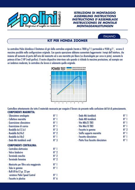
ISTRUZIONI DI MONTAGGIO ASSEMBLING INSTRUCTIONS INSTRUCTIONS D’ASSEMBLAGE INSTRUCCIONES DE MONTAJE MONTAGEANLEITUNGEN KIT PER HONDA ZOOMER ITALIANO La centralina Polini disinibisce il limitatore di giri della centralina originale (tarata a 7800 g/1') portandola a 9500 g/1', ovvero il massimo possibile nella configurazione originale. Con questa operazione abbiamo aumentato leggermente i tempi dell'iniettore, che insieme all'aumento di porta dell'aria del manicotto ed a una marmitta più libera (se disomologata per corse in pista), aumenta la potenza di ben 2 HP (vedi grafico). Il nostro dispositivo interviene solo quando si richiede la massima prestazione, ad esempio con un'andatura moderata, la centralina che lavora è solamente quella originale. POWER TEST Controllare attentamente che tutto il materiale necessario per eseguire il lavoro sia presente nella confezione del kit di potenziamento. COMPONENTI MARMITTA: - Silenziatore omologato N° 1 - Dado M6 Autoblock N° 1 - Collettore marmitta N° 1 - Dado M8 Autoblock N° 1 - Guarnizione silenziatore N° 1 - Vite M8x25 TBEI N° 1 - Guarnizione di scarico N° 1 - Vite M6x10 TBEI N° 1 - Rondella 6x12,5x1 N° 3 - Fascetta in gomma N° 2 - Rondella 8x24x2 N° 2 - Staffa supporto marmitta N° 1 - Rondella 6x18x2 N° 1 - Fascetta silenziatore N° 1 - Dado M6 Autoblock ovali N° 3 - Piatto fissa fascetta silenziatore N° 1 COMPONENTI CENTRALINA: - Centralina elettronica N° 1 - Velcro biadesivo N° 2 - Terminale maschio N° 2 - Terminale femmina N° 2 - Manicotto per filtro aria maggiorato N° 1 - Tubo in gomma N° 1 - Rulli Ø16x13 gr. 23 per variatore Polini Speed Control N° 1 - Fascette in plastica N° 6
- Page 2 and 3: MONTAGGIO DELLA MARMITTA Smontare l
- Page 4 and 5: GEARCASE COMPONENTS: - Electronic g
- Page 6 and 7: - Ecrou M6 Autoblock ovale N° 3 CO
- Page 8 and 9: - Tuerca M6 Autoblock oval N° 3 CO
- Page 10 and 11: - Unterlegscheibe 6x18x2 1 Stk. - M
- Page 12 and 13: A B C D E RACCORDO HONDA HONDA CONN
- Page 14: Questo modello d’impianto di scar
ISTRUZIONI DI MONTAGGIO<br />
ASSEMBLING INSTRUCTIONS<br />
INSTRUCTIONS D’ASSEMBLAGE<br />
INSTRUCCIONES DE MONTAJE<br />
MONTAGEANLEITUNGEN<br />
KIT PER HONDA ZOOMER<br />
ITALIANO<br />
La centralina <strong>Polini</strong> disinibisce il limitatore di giri della centralina originale (tarata a 7800 g/1') portandola a 9500 g/1', ovvero il<br />
massimo possibile nella configurazione originale. Con questa operazione abbiamo aumentato leggermente i tempi dell'iniettore, che<br />
insieme all'aumento di porta dell'aria del manicotto ed a una marmitta più libera (se disomologata per corse in pista), aumenta la<br />
potenza di ben 2 HP (vedi grafico). Il nostro dispositivo interviene solo quando si richiede la massima prestazione, ad esempio con<br />
un'andatura moderata, la centralina che lavora è solamente quella originale.<br />
<strong>POWER</strong> <strong>TEST</strong><br />
<br />
<br />
<br />
<br />
<br />
<br />
<br />
<br />
<br />
<br />
<br />
<br />
<br />
Controllare attentamente che tutto il materiale necessario per eseguire il lavoro sia presente nella confezione del kit di potenziamento.<br />
COMPONENTI MARMITTA:<br />
- Silenziatore omologato N° 1<br />
- Dado M6 Autoblock N° 1<br />
- Collettore marmitta N° 1<br />
- Dado M8 Autoblock N° 1<br />
- Guarnizione silenziatore N° 1<br />
- Vite M8x25 TBEI N° 1<br />
- Guarnizione di scarico N° 1<br />
- Vite M6x10 TBEI N° 1<br />
- Rondella 6x12,5x1 N° 3<br />
- Fascetta in gomma N° 2<br />
- Rondella 8x24x2 N° 2<br />
- Staffa supporto marmitta N° 1<br />
- Rondella 6x18x2 N° 1<br />
- Fascetta silenziatore N° 1<br />
- Dado M6 Autoblock ovali N° 3<br />
- Piatto fissa fascetta silenziatore N° 1<br />
COMPONENTI CENTRALINA:<br />
- Centralina elettronica N° 1<br />
- Velcro biadesivo N° 2<br />
- Terminale maschio N° 2<br />
- Terminale femmina N° 2<br />
- Manicotto per filtro aria maggiorato N° 1<br />
- Tubo in gomma N° 1<br />
- Rulli Ø16x13 gr. 23 per<br />
variatore <strong>Polini</strong> Speed Control N° 1<br />
- Fascette in plastica N° 6
MONTAGGIO DELLA MARMITTA<br />
Smontare la marmitta originale facendo attenzione a staccare la spina della sonda lamda (foto A). Montare il collettore di scarico con il<br />
silenziatore inserendo la guarnizione, usando rondelle e dadi autobloccanti ovali presenti nella confezione.<br />
Montare la staffa e la fascetta con l'apposita gomma, chiudere il tutto e riposizionare la sonda lamda come in origine (foto B).<br />
Per il fissaggio del parafango dietro al silenziatore è presente una piastrina avvitata che vi consigliamo di fissare con della Loctite<br />
blocca filetti.<br />
Attenzione! Consigliamo dopo i primi 15 minuti di funzionamento, di ricontrollare il serraggio delle viti e dei dadi della marmitta.<br />
La marmitta come viene consegnata è omologata e di conseguenza limitata. Per eventuali corse in pista, vi consigliamo di togliere il<br />
tubetto lasciando però la rondella (foto C). Così facendo si ottiene un buon compromesso tra potenza e la rumorosità.<br />
Attenzione! Più si libera la marmitta più si raggiungono alte prestazioni a discapito della rumorosità!<br />
MONTAGGIO DEL MANICOTTO<br />
Smontare completamente il filtro e sostituire il manicotto originale con il manicotto <strong>Polini</strong> completamente intercambiabile.<br />
Attenzione, il manicotto originale è incollato, smontarlo e pulire i residui di colla. Se l'inserimento di questo sul filtro originale non<br />
risulta immediato, scaldarlo a 30°/40°c per ammorbidirlo o molare con una fresa il filtro originale.<br />
Svitare il raccordo dalla cassa filtro originale (foto D) e inserire il tubo in dotazione mandando lo scarico a terra. Fissare il tutto con<br />
2/3 fascette in plastica.<br />
MONTAGGIO CENTRALINA<br />
Per un corretto montaggio della centralina, seguire passo dopo passo le istruzioni qui di seguito.<br />
Attenzione! Controllate che la chiave dello scooter sia in posizione “OFF”.<br />
Smontare la sella ed il poggiapiedi. Prendere il cavo rosa/blu che fuoriesce dall'iniettore (togliendo eventualmente un po' di isolante<br />
nero) e tagliare a circa 5 cm (foto E).<br />
Prendere un terminale femmina in dotazione (per il montaggio corretto vedi foto F) e fissarlo alla parte di cavo rosa/blu tagliato che<br />
esce dall'iniettore. Collegare un terminale maschio al restante cavo tagliato rosa/blu, che arriva dalla centralina Honda.<br />
Ora innestare i due terminali appena inseriti al cablaggio della centralina <strong>Polini</strong> (foto G):<br />
femmina con il cavo rosa 1 - maschio con il cavo blu 4.<br />
Disinnestare il connettore del corpo farfallato e liberare dalla guaina il filo giallo/blu (foto H) dalla centralina Honda.<br />
Tagliarlo e fissare i due terminali in dotazione (in questo caso non è importante la collocazione maschio-femmina).<br />
Prendere il cavo bianco 2,3 della centralina <strong>Polini</strong> e fissarlo ai terminali appena inseriti sul cavo giallo/blu della centralina Honda<br />
(foto I).<br />
Staccare il cavo rosso/nero originale dalla bobina (foto L) e congiungerlo al cavo 6 (rosso) della centralina <strong>Polini</strong>. Collegare il cavo 5<br />
(rosso) della centralina <strong>Polini</strong> alla bobina.<br />
Staccare il cavo giallo/blu originale dalla bobina (foto M) e congiungerlo al cavo 9 (giallo) della centralina <strong>Polini</strong>. Collegare il cavo 8<br />
(giallo) della centralina <strong>Polini</strong> alla bobina.<br />
Svitare la vite della massa bobina e inserire il cavo 7, già munito di occhiello e richiudere (foto N).<br />
Fissare il cablaggio con le fascette di plastica in modo che sia ben fermo.<br />
Pulire con diluente la superficie sotto il copripedana e sotto la centralina (foto O). Incollare il biadesivo con il velcro per il fissaggio<br />
della centralina.<br />
VARIATORE<br />
Questo kit di modifica è stato studiato e messo a punto con il variatore <strong>Polini</strong> Speed Control cod. 241.626.<br />
È quindi obbligatorio avere il variatore montato e modificarlo con i rulli presenti nel kit.
POS.<br />
1<br />
2<br />
3<br />
4<br />
5<br />
6<br />
7<br />
8<br />
9<br />
CONNESSIONE CENTRALINA POLINI<br />
COLORE CENTRALINA POLINI COLORE HONDA ZOOMER<br />
ROSA<br />
ROSA/BLU<br />
BIANCO<br />
GIALLO/BLU<br />
BIANCO<br />
GIALLO/BLU<br />
BLU<br />
ROSA/BLU<br />
ROSSO<br />
ROSSO<br />
ROSSO<br />
ROSSO<br />
NERO<br />
MASSA<br />
GIALLO<br />
GIALLO<br />
GIALLO<br />
GIALLO<br />
RIF.<br />
FOTO F<br />
FOTO H<br />
FOTO H<br />
FOTO F<br />
FOTO I<br />
FOTO I<br />
FOTO M<br />
FOTO L<br />
FOTO L<br />
KIT FOR HONDA ZOOMER<br />
ENGLISH<br />
The <strong>Polini</strong> gearcase disables the rpm limiting device in the original gearcase (set at 7800 g/1') taking it to 9500 g/1', i.e. the max<br />
possible with the original configuration. We have thus slightly increased the injector times, which together with an increase in the sleeve<br />
air flow and a freer exhaust (if converted for track racing), increases the power by up to 2 HP (see graph).<br />
Our device only intervenes when you require max performance, i.e. at a steady pace, only the original gearcase will work.<br />
<strong>POWER</strong> <strong>TEST</strong><br />
<br />
<br />
<br />
<br />
<br />
<br />
<br />
<br />
<br />
<br />
<br />
<br />
<br />
Check carefully that all the material needed for assembly is included in the enhancement kit.<br />
EXHAUST COMPONENTS:<br />
- Type-approved silencer N° 1<br />
- Nut M6 Autoblock N° 1<br />
- Exhaust manifold N° 1<br />
- Nut M8 Autoblock N° 1<br />
- Silencer gasket N° 1<br />
- Screw M8x25 TBEI N° 1<br />
- Exhaust gasket N° 1<br />
- Screw M6x10 TBEI N° 1<br />
- Washer 6x12,5x1 N° 3<br />
- Rubber band N° 2<br />
- Washer 8x24x2 N° 2<br />
- Exhaust bracket N° 1<br />
- Washer 6x18x2 N° 1<br />
- Silencer band N° 1<br />
- Nut M6 Oval Autoblock N° 3<br />
- Fixing plate for silencer band N° 1
GEARCASE COMPONENTS:<br />
- Electronic gearcase N° 1<br />
- Biadhesive Velcro N° 2<br />
- Male terminal N° 2<br />
- Female terminal N° 2<br />
- Boosted air filter sleeve N° 1<br />
- Rubber hose N° 1<br />
- Rolls Ø16x13 23g for <strong>Polini</strong> Speed Control N° 1<br />
- Plastic clip N° 6<br />
FITTING THE EXHAUST<br />
Remove the original exhaust, making sure you detach the lambda probe (photo A).<br />
Fit the exhaust manifold with the silencer by first inserting the gasket, using the washers, oval Autoblock nuts in the kit.<br />
Fit the bracket and the clip with its rubber band, tighten everything and then return the lambda probe as before (photo B).<br />
There is a screwed plate behind the silencer for fixing the mudguard: we recommend using Loctite glue to stop the thread from slipping.<br />
Caution! Check the tightening of the screws and the nuts on the exhaust after the first 15 minutes of use.<br />
The supplied exhaust is type-approved and thus limited. If you want to race on a track, we recommend removing the tube, but leaving<br />
the washer (photo C). That way you get a good compromise between power and noise.<br />
Caution! The more you free up the exhaust to get better performance, the greater the noise!<br />
FITTING THE SLEEVE<br />
Completely remove the filter and replace the original sleeve with the <strong>Polini</strong> sleeve (interchangeable).<br />
Caution! The original sleeve is stuck, remove it and clean away the glue residual.<br />
If you have difficulties in inserting this on the original filter, warm it to about 30-40°C to soften it or hone the original filter.<br />
Extract the fitting from the original filter case (photo D) and insert the tube provided in the kit, making sure the exhaust faces<br />
downwards. Fix all the parts with 2-3 plastic clips.<br />
FITTING THE GEARCASE<br />
Follow the steps below to ensure the gearcase is fitted properly.<br />
Caution! Make sure that the scooter key is in the “OFF” position!<br />
Remove seat and footboards. Take hold of the pink/blue cable coming out of the injector (removing a bit of black insulating material if<br />
necessary) and cut at about 5 cm (photo E).<br />
Take a female terminal (for the correct fitting see photo F) from the kit and fix to the cut end of the pink/blue cable coming from the<br />
injector. Connect a male terminal to the other end of the pink/blue cable (coming from the Honda gearcase).<br />
Connect the two terminals to the <strong>Polini</strong> gearcase (photo G): Female with pink cable 1 - male with blue cable 4.<br />
Detach the cable connector of the throttle body and free yellow/blue thread in the sheath (photo H) from the Honda gearcase.<br />
Cut and fix the two terminals provided in the kit (the male/female combination does not matter here).<br />
Take white cables 2-3 belonging to the <strong>Polini</strong> gearcase and fix to the terminals just inserted on the yellow/blue cable on the Honda<br />
gearcase (photo I).<br />
Detach the original red/black cable from the coil (photo L) and join to cable 6 (red) on the <strong>Polini</strong> gearcase. Connect cable 5 (red) on<br />
the <strong>Polini</strong> gearcase to the coil.<br />
Detach the original yellow/blue cable from the coil (photo M) and join to cable 9 (yellow) on the <strong>Polini</strong> gearcase.<br />
Connect cable 8 (yellow) on the <strong>Polini</strong> gearcase to the coil.<br />
Undo the coil earthing screw and insert cable 7, already fitted with an eyelet, and then tighten the screw again (photo N).<br />
Fix the cables with the plastic clips.<br />
Clean the surface under the footboard cover and under the gearcase cover (photo O). Use the biadhesive Velcro to fix the gearcase.<br />
SPEED CONTROL<br />
This conversion kit has been designed and developed for use with the <strong>Polini</strong> Speed Control code 241.626.<br />
This speed control must, therefore, be fitted and converted with the rollers provided in this kit.
POS.<br />
1<br />
2<br />
3<br />
4<br />
5<br />
6<br />
7<br />
8<br />
9<br />
POLINI GEARCASE CONNECTION<br />
POLINI GEARCASE COLOUR HONDA ZOOMER COLOUR<br />
PINK<br />
PINK/BLUE<br />
WHITE<br />
YELLOW/BLUE<br />
WHITE<br />
YELLOW/BLUE<br />
BLUE<br />
PINK/BLUE<br />
RED<br />
RED<br />
RED<br />
RED<br />
BLACK<br />
EARTH<br />
YELLOW<br />
YELLOW<br />
YELLOW<br />
YELLOW<br />
REF.<br />
PICT. F<br />
PICT. H<br />
PICT. H<br />
PICT. F<br />
PICT. I<br />
PICT. I<br />
PICT. M<br />
PICT. L<br />
PICT. L<br />
KIT POUR HONDA ZOOMER<br />
FRANÇAIS<br />
La centrale <strong>Polini</strong> débloque le limiteur de tours de la centrale d'origine (réglée sur 7800 trs/1') et la porte à 9500 trs/1', c'est-à-dire<br />
au maximum possible dans la configuration d'origine. Cette opération permet d'augmenter légèrement les temps de l'injecteur qui,<br />
grâce à l'augmentation du débit d'air du manchon et au pot d'échappement plus libre (si déshomologué pour course sur piste),<br />
augmente la puissance de 2 HP (voir graphique). Notre dispositif n'intervient qu'en cas de demande d'un maximum de performances;<br />
par exemple: à une vitesse modérée, seule la centrale d'origine travaille.<br />
<strong>POWER</strong> <strong>TEST</strong><br />
<br />
<br />
<br />
<br />
<br />
<br />
<br />
<br />
<br />
<br />
<br />
<br />
<br />
Contrôler avec soin si le kit additionnel d'augmentation de puissance contient bien tout le matériel nécessaire à l'exécution du montage.<br />
COMPOSANTS DU POT D'ECHAPPEMENT:<br />
- Silencieux homologué N° 1<br />
- Ecrou M6 Autoblock<br />
- Ecrou M8 Autoblock<br />
N° 1<br />
N° 1<br />
- Collecteur pot d'échappement N° 1<br />
- Vis M8x25 TBEI N° 1<br />
- Joint silencieux N° 1<br />
- Vis M6x10 TBEI N° 1<br />
- Joint d'échappement N° 1<br />
- Bride en caoutchouc N° 2<br />
- Rondelle 6x12,5x1 N° 3<br />
- Étrier de support du pot N° 1<br />
- Rondelle 8x24x2 N° 2<br />
- Bride silencieux N° 1<br />
- Rondelle 6x18x2 N° 1<br />
- Plaque fixation bride du silencieux N° 1
- Ecrou M6 Autoblock ovale N° 3<br />
COMPOSANTS DE LA CENTRALE:<br />
- Centrale électronique N° 1<br />
- Velcro bi adhésif N° 2<br />
- Borne femelle N° 2<br />
- Borne mâle N° 2<br />
- Manchon pour filtre à air agrandi N° 1<br />
- Tube caoutchouc N° 1<br />
- Rouleaux Ø16x13 23 grammes pour variateur <strong>Polini</strong> Speed Control N° 1<br />
- Bride en plastique N° 6<br />
MONTAGE DU POT D'ECHAPPEMENT<br />
Démonter le pot d'échappement d'origine en faisant bien attention à ce que la sonde lambda soit débranchée (photo A).<br />
Monter le collecteur d'échappement et le silencieux en insérant le joint et en utilisant les rondelles et les écrous autobloquants ovales<br />
qui se trouvent dans la confection. Monter l'étrier et la bride avec caoutchouc réservé à cet effet, serrer le tout et remettre la sonde<br />
lambda dans sa position d'origine (photo B).<br />
Pour fixer le garde-boue, on dispose d'une plaque vissée arrière au silencieux, qu'on conseille de fixer avec de la Loctite bloque filets.<br />
Attention! On conseille de contrôler de nouveau le serrage des vis et des écrous du pot d'échappement au bout des 15 premières<br />
minutes de fonctionnement.<br />
Le pot d'échappement est homologué à la livraison et par conséquent limité. Pour d'éventuelles courses sur piste, on conseille de retirer<br />
le petit tube, mais de laisser la rondelle (photo C). On obtiendra ainsi un bon compromis entre puissance et bruit dégagé.<br />
Attention! Plus on libère le pot d'échappement, plus les performances atteintes sont élevées au détriment du bruit !<br />
MONTAGE DU MANCHON<br />
Démonter entièrement le filtre et remplacer le manchon d'origine par un manchon <strong>Polini</strong> complètement interchangeable.<br />
Attention, le manchon original est collé, le démonter et essuyer las déchets de colle.<br />
Si le montage de ce dernier sur le filtre d'origine n'est pas immédiat, le réchauffer à 30°/40°C pour l'assouplir ou fraiser le filtre<br />
d'origine. Dévisser le raccord en le retirant de la caisse filtre d'origine (photo D) et introduire le tube fourni en dirigeant l'échappement<br />
vers le bas. Fixer le tout à l'aide de 2/3 brides en plastique.<br />
MONTAGE DE LA CENTRALE<br />
Pour monter correctement la centrale, suivre pas à pas les instructions ci-dessous.<br />
Attention! Contrôler que la clé du scooter est bien sur “OFF”.<br />
Démonter la selle et le repose-pied. Prendre le câble rose/bleu qui sort de l'injecteur (enlever éventuellement un peu de isolant noir)<br />
et le couper à environ 5 cm (photo E). Prendre la borne femelle fournie (pour le montage correct voire la photo F) et la fixer à la partie<br />
de câble rose/bleu coupée qui sort de l'injecteur. Raccorder une borne mâle au reste du câble coupé rose/bleu, qui sort de la centrale<br />
Honda. Brancher maintenant les deux bornes déjà insérées au câblage de la centrale <strong>Polini</strong> (photo G):<br />
la borne femelle au câble rose 1 - la borne mâle au câble bleu 4.<br />
Débrancher le connecteur du corps de papillon et enlever la gaine du fil 1, jaune/bleu (photo H) de la centrale Honda. Le couper et<br />
fixer les deux bornes fournies (dans ce cas la disposition mâle-femelle n'est pas importante). Prendre le câble blanc 2,3 de la centrale<br />
<strong>Polini</strong> et le fixer aux bornes déjà insérées sur la câble jaune /bleu de la centrale Honda (photo I).<br />
Détacher le câble rouge/noir d'origine et le retirer de la bobine (photo L) pour le raccorder au câble 6 (rouge) de la centrale <strong>Polini</strong>.<br />
Relier le câble 5 (rouge) de la centrale <strong>Polini</strong> à la bobine.<br />
Détacher le câble jaune/bleu d'origine et le retirer de la bobine (photo M) pour le raccorder au câble 9 (jaune) de la centrale <strong>Polini</strong>.<br />
Relier le câble 8 (jaune) de la centrale <strong>Polini</strong> à la bobine.<br />
Desserrer la vis de la masse bobine et introduire le câble 7 déjà muni d'œillet, puis refermer (photo N).<br />
Retenir le câblage à l'aide de brides en plastique de façon à ce qu'il soit bien fixé. Nettoyer au diluant la surface en dessous du couvre<br />
plancher et sous la centrale (photo O). Coller le bi adhésif avec velcro pour fixer la centrale.<br />
VARIATEUR<br />
Ce kit de modification a été étudié et mis au point avec le variateur <strong>Polini</strong> Speed Control code 241.626.
POS.<br />
1<br />
2<br />
3<br />
4<br />
5<br />
6<br />
7<br />
8<br />
9<br />
CONNEXION DE LA CENTRALE POLINI<br />
COULEUR HONDA ZOOMER<br />
ROSE/BLUE<br />
GIALLO/BLUE<br />
GIALLO/BLUE<br />
ROSE/BLUE<br />
ROUGE<br />
ROUGE<br />
MASSE<br />
JAUNE<br />
JAUNE<br />
COULEUR DE LA CENTRALE POLINI<br />
ROSE<br />
BLANC<br />
BLANC<br />
BLUE<br />
ROUGE<br />
ROUGE<br />
NOIR<br />
JAUNE<br />
JAUNE<br />
REF.<br />
PHOTO F<br />
PHOTO H<br />
PHOTO H<br />
PHOTO F<br />
PHOTO I<br />
PHOTO I<br />
PHOTO M<br />
PHOTO L<br />
PHOTO L<br />
KIT PARA HONDA ZOOMER<br />
ESPAÑOL<br />
Il est donc obligatoire de monter ce variateur et de le modifier à l'aide des rouleaux présents dans le kit.<br />
La centralita <strong>Polini</strong> desinhibe el limitador de revoluciones de la centralita original (regulada a 7800 rpm), llevándola a 9500 rpm, el<br />
máximo posible en la configuración original. Con esta operación, hemos aumentado ligeramente los tiempos del inyector que, junto con<br />
el aumento de caudal de aire del manguito y un tubo de escape más libre (no homologado, para carreras en pista) proporciona hasta 2<br />
HP más de potencia (ver gráfico). Nuestro dispositivo sólo interviene cuando se necesitan las máximas prestaciones. Por ejemplo: a una<br />
<strong>POWER</strong> <strong>TEST</strong><br />
<br />
<br />
<br />
<br />
<br />
<br />
<br />
<br />
<br />
<br />
<br />
<br />
<br />
velocidad moderada, funcionará únicamente la centralita original.<br />
Controlar atentamente que la caja del kit de potenciación contenga todo el<br />
material necesario para el trabajo.<br />
COMPONENTES TUBO DE ESCAPE:<br />
- Silenciador homologado N° 1<br />
- Colector tubo de escape N° 1<br />
- Guarnición silenciador N° 1<br />
- Guarnición de escape N° 1<br />
- Arandela 6x12,5x1 N° 3<br />
- Arandela 8x24x2 N° 2<br />
- Arandela 6x18x2 N° 1<br />
- Tuerca M6 Autoblock N° 1<br />
- Tuerca M8 Autoblock N° 1<br />
- Tornillo M8x25 TBEI N° 1<br />
- Tornillo M6x10 TBEI N° 1<br />
- Abrazadera de goma N° 2<br />
- Soporte estribo de escape N° 1<br />
- Abrazadera silenciador N° 1<br />
- Plancha de sujeción abrazadera silenciador N° 1
- Tuerca M6 Autoblock oval N° 3<br />
COMPONENTES CENTRALITA:<br />
- Centralita electrónica N° 1<br />
- Velcro biadhesivo N° 2<br />
- Terminal macho N° 2<br />
- Terminal hembra N° 2<br />
- Manguito para filtro de aire agrandado N° 1<br />
- Tubo de goma N° 1<br />
- Rodillos Ø16x13 gr. 23 para variador <strong>Polini</strong> Speed Control N° 1<br />
- Abrazaderas de plástico N° 6<br />
MONTAJE DEL TUBO DE ESCAPE<br />
Desmontar el tubo de escape original asegurándose de desconectar la clavija de la sonda lambda (foto A).<br />
Montar el colector de escape con el silenciador introduciendo la guarnición, usando para ello las arandelas y tuercas autobloqueantes<br />
ovales contenidas en la caja. Montar el estribo y la abrazadera con su goma correspondiente, cerrar todo y colocar de nuevo la sonda<br />
lambda en su posición original (foto B). Para fijar el guardabarros trasero al silenciador, se utiliza una pletina atornillada, que<br />
aconsejamos asegurar con sellador de roscas Loctite.<br />
¡Atención! Aconsejamos controlar de nuevo el apriete de los tornillos y de las tuercas del tubo de escape después de los primeros 15<br />
minutos de funcionamiento. El tubo de escape se entrega homologado y, por consiguiente, limitado. Para carreras en pista, aconsejamos<br />
quitar el tubito, dejando, sin embargo, la arandela (foto C). De ese modo, se obtiene un buen compromiso entre potencia y niveles<br />
de ruido. ¡Atención! Cuando más se libera el tubo de escape, más altas son las prestaciones alcanzadas, pero también mayores los<br />
niveles de ruido.<br />
MONTAJE DEL MANGUITO<br />
Desmontar completamente el filtro y sustituir el manguito original con el manguito <strong>Polini</strong> completamente intercambiable.<br />
¡Atención! El manguito original tiene pegamento, desmontarlo y limpiar los resíduos de pegamento. Si el manguito no entra<br />
fácilmente, calentarlo a 30°/40°C para ablandarlo, o fresar el filtro original. Destornillar el empalme de la caja del filtro original (foto<br />
D) e introducir el tubo servido, dirigiendo el escape al suelo. Fijar todo con 2/3 abrazaderas de plástico.<br />
MONTAJE DE LA CENTRALITA<br />
Para un correcto montaje de la centralita, seguir paso a paso las instrucciones que se dan a continuación.<br />
¡Atención! Controlar que la llave del scooter esté en posición “OFF”. Desmontar el sillín y el apoyo de los pies. Tomar el cable<br />
rosa/azul que sale del inyector (eventualmente quitar un poco de aislante negro) y cortar a 5 cm aproximadamente (foto E).<br />
Tomar una de las terminales hembra servidas (para el montaje correcto ver la foto F) y fijarla en la parte de cable rosa/azul cortado<br />
que sale del inyector. Conectar una terminal macho al cable cortado rosa/azul restante, que viene de la centralita Honda.<br />
Enchufar ahora los dos terminales ya insertados al cableado de la centralita <strong>Polini</strong> (foto G):<br />
hembra con el cable rosa 1 - macho con el cable azul 4.<br />
Desenchufar el conectador del cuerpo de aceleración y liberar de la vaina el hilo 1, amarillo/azul (foto H) de la centralita Honda.<br />
Cortarlo y fijar las dos terminales servidas (en este caso no es importante la posición macho-hembra).<br />
Tomar el cable blanco 2,3 de la centralita <strong>Polini</strong> y fijarlo en las terminales que han sido ya insertado en el cable amarillo/azul de la<br />
centralita Honda (foto I).<br />
Desconectar el cable rojo/negro original de la bobina (foto L) y conectarlo al cable 6 (rojo) de la centralita <strong>Polini</strong>. Conectar el cable 5<br />
(rojo) de la centralita <strong>Polini</strong> a la bobina.<br />
Desconectar el cable amarillo/azul original de la bobina (foto M) y conectarlo al cable 9 (amarillo) de la centralita <strong>Polini</strong>. Conectar el<br />
cable 8 (amarillo) de la centralita <strong>Polini</strong> a la bobina.<br />
Aflojar el tornillo de tierra de la bobina e introducir el cable 7, ya ojalado, y apretar de nuevo (foto N).<br />
Fijar el cableado con las abrazaderas de plástico de modo que quede bien seguro. Limpiar con diluyente la superficie bajo la cubierta<br />
del estribo y bajo la centralita (foto O). Encolar el biadhesivo con el velcro para fijar la centralita.<br />
VARIADOR
POS.<br />
1<br />
2<br />
3<br />
4<br />
5<br />
6<br />
7<br />
8<br />
9<br />
CONECTADOR CENTRALITA POLINI<br />
COLOR CENTRALITA POLINI COLOR HONDA ZOOMER<br />
ROSA<br />
ROSA/AZUL<br />
BLANCO<br />
AMARILLO/AZUL<br />
BLANCO<br />
AMARILLO/AZUL<br />
AZUL<br />
ROSA/AZUL<br />
ROJO<br />
ROJO<br />
ROJO<br />
ROJO<br />
NEGRO<br />
TIERRA<br />
AMARILLO<br />
AMARILLO<br />
AMARILLO<br />
AMARILLO<br />
RIF.<br />
FOTO F<br />
FOTO H<br />
FOTO H<br />
FOTO F<br />
FOTO I<br />
FOTO I<br />
FOTO M<br />
FOTO L<br />
FOTO L<br />
TUNING-KIT FÜR HONDA ZOOMER<br />
DEUTSCH<br />
Este kit de modificación ha sido estudiado y puesto a punto con el variador <strong>Polini</strong> Speed Control cód. 241.626.<br />
Por lo tanto, es obligatorio tener el variador montado y modificarlo con los rodillos presentes en el kit.<br />
Das <strong>Polini</strong>-Steuergerät befreit den Drehzahlbegrenzer des (auf 7800 U/m geeichten) Original-Steuergeräts und erhöht die Drehzahl<br />
auf 9500 U/m, das heißt den in der Originalkonfiguration möglichen Höchstwert. Mit diesem Vorgang wurden die Zeiten des<br />
Einspritzers geringfügig erhöht, wodurch zusammen mit der Erhöhung der Luftmenge der Muffe und einem freieren Auspuff (wenn für<br />
<strong>POWER</strong> <strong>TEST</strong><br />
<br />
<br />
<br />
<br />
<br />
<br />
<br />
<br />
<br />
<br />
<br />
<br />
<br />
Renneinsatz nicht zugelassen), die Leistung um gute 2 PS (siehe Graphik) erhöht wird. Unsere Vorrichtung spricht nur an, wenn<br />
Höchstleistung gefordert wird, bei gemäßigtem Tempo zum Beispiel arbeitet nur das Original-Steuergerät.<br />
Kontrollieren Sie genau, ob das komplette für die Durchführung der Arbeit<br />
erforderliche Material in der Verpackung des Tuning-Kits enthalten ist.<br />
BAUTEILE AUSPUFF<br />
- Zugelassener Schalldämpfer 1 Stk.<br />
- Rohrkrümmer 1 Stk.<br />
- Schalldämpferdichtung 1 Stk.<br />
- Abgasdichtung 1 Stk.<br />
- Unterlegscheibe 6x12,5x1 3 Stk.<br />
- Unterlegscheibe 8x24x2 2 Stk.<br />
- Mutter M6 selbstsichernd 1 Stk.<br />
- Mutter M8 selbstsichernd 1 Stk.<br />
- Schraube M8x25 TBEI 1 Stk.<br />
- Schraube M6x10 TBEI 1 Stk.<br />
- Gummischelle 2 Stk.<br />
- Halterung für Auspuff 1 Stk.<br />
- Schalldämpferschellen 1 Stk.<br />
- Befestigungsplatte für Endschalldämpfer-Schellen 1 Stk.
- Unterlegscheibe 6x18x2 1 Stk.<br />
- Mutter M6 selbstsichernd, oval 3 Stk.<br />
BAUTEILE STEUERGERÄT:<br />
- Elektronik-steuergerät 1 Stk.<br />
- Doppelvelcro 2 Stk.<br />
- Endverschluss, Stecker 2 Stk.<br />
- Endverschluss, Buchse 2 Stk.<br />
- Muffe für vergrößerten Luftfilter 1 Stk.<br />
- Gummischlauch 1 Stk.<br />
- Rollen Ø16x13 23 g für Variator <strong>Polini</strong> Speed Control 1 Stk.<br />
- Plastikschellen 6 Stk.<br />
MONTAGE DES AUSPUFFS<br />
Den Originalauspuff ausbauen, dazu muss der Stecker der Lambdasonde herausgezogen werden (Foto A).<br />
Den Auspuffkrümmer mit dem Schalldämpfer montieren, dabei die Dichtung einlegen und die in der Packung enthaltenen<br />
Unterlegscheiben und ovalen selbstsichernden Muttern verwenden. Den Bügel und die Schelle mit dem entsprechenden Gummiteil<br />
montieren, das Ganze schließen und die Lambdasonde in der ursprünglichen Position wieder einbauen (Foto B).<br />
Für die Befestigung des Kotflügels befindet sich hinter dem Schalldämpfer eine festgeschraubte Platte. Es empfiehlt sich, sie mit Loctite<br />
Schraubensicherung zu sichern.<br />
Achtung! Wir empfehlen, nach den ersten 15 Minuten Betrieb den Anzug der Schrauben und der Muttern des Auspuffs noch einmal zu<br />
kontrollieren.<br />
Der Auspuff ist bei Auslieferung für den Straßenverkehr zugelassen und folglich begrenzt.<br />
Für eventuelle Renneinsätze empfehlen wir, den Schlauch zu entfernen, die Unterlegscheibe jedoch eingebaut zu lassen (Foto C).<br />
Auf diese Weise wird ein guter Kompromiss zwischen Leistung und Geräuschpegel erzielt.<br />
Achtung! Je mehr der Auspuff freigelegt wird, desto höhere Leistungen werden auf Kosten des Geräuschpegels erzielt!<br />
MONTAGE DER MUFFE<br />
Den Filter komplett ausbauen und die Originalmuffe durch die vollständig austauschbare <strong>Polini</strong>-Muffe ersetzen. Achtung, die originale<br />
Muffe ist mit Klebstoff befestigt; nach der Demontage von ev. Klebstoffreste reinigen. Wenn sie sich nicht sofort auf den Originalfilter<br />
aufsetzen lässt, die Muffe auf 30/40 °C anwärmen, um sie zu erweichen oder den Originalfilter etwas ausfräsen.<br />
Das Verbindungsstück vom Originalfiltergehäuse abschrauben (Foto D), den mitgelieferten Schlauch einsetzen und den Auslass zum<br />
Boden ausrichten. Das Ganze mit 2/3 Plastikschellen befestigen.<br />
MONTAGE DES STEUERGERÄTS<br />
Für eine korrekte Montage des Steuergeräts müssen die nachfolgenden Anleitungen Schritt für Schritt befolgt werden.<br />
Achtung! Sicherstellen, dass der Zündschlüssel des Rollers auf “OFF” steht.<br />
Den Sattel und das Fußbrett ausbauen. Das aus dem Einspritzer kommende rosa/blau gekennzeichnete Kabel nehmen (Falls nötig, ein<br />
Teil vom schwarzem Abdichtungsmaterial abreiben) und auf etwa 5 cm abschneiden (Foto E).<br />
Einen mitgelieferten Buchsen-Endverschluss (für die richtige Montage sehen Sie Foto F) nehmen und an dem aus dem Einspritzer<br />
kommenden Teil des abgeschnittenen, rosa/blau gekennzeichneten Kabels befestigen. Einen Stecker-Endverschluss am restlichen, vom<br />
Honda-Steuergerät kommenden Teil des abgeschnittenen, rosa/blau gekennzeichneten Kabels befestigen.<br />
Nun zwei Endverschlüsse an der Verdrahtung des <strong>Polini</strong>-Steuergeräts anschließen (Foto G):<br />
Die Buchse mit dem rosa Kabel 1 - den Stecker mit dem blauen Kabel 4.<br />
Den Konnektor von der Drosselkappe trennen und den gelb/blauen Draht 1 vom Honda Steuergerät abmanteln (Foto H). Den Draht<br />
abschneiden und die zwei mitgelieferten Endverschlüsse anbringen (in diesem Fall ist die Anordnung von Stecker und Buchse egal).<br />
Das weiße Kabel 2,3 des <strong>Polini</strong>-Steuergeräts muss an die Stecker befestigt werden, die gerade am<br />
Blau/gelbem Kabel des Honda-Steuergeräts angebracht wurden (Foto I).<br />
Das rote/schwarze Originalkabel von der Spule trennen (Foto L) und mit dem Kabel 6 (rot) des <strong>Polini</strong>-Steuergeräts verbinden.<br />
Das Kabel 5 (rot) des <strong>Polini</strong>-Steuergeräts an der Spule anschließen.<br />
Das gelbe/blaue Originalkabel von der Spule trennen (Foto M) und mit dem Kabel 9 (gelb) des <strong>Polini</strong>-Steuergeräts verbinden.
Das Kabel 8 (gelb) des <strong>Polini</strong>-Steuergeräts an der Spule anschließen.<br />
Die Schraube der Spulenmasse lösen und das bereits mit einer Öse versehene Kabel 7 einstecken, dann wieder schließen (Foto N).<br />
Die Verdrahtung mit den Plastikschellen befestigen, damit es gut gesichert ist.<br />
Die Fläche unter der Fußbrettabdeckung und unter dem Steuergerät mit Lösemittel reinigen (Foto O).<br />
Zur Befestigung des Steuergeräts das Doppelklebeband mit dem Velcro festkleben.<br />
VARIATOR<br />
Dieses Tuning-Kit wurde mit dem Variator <strong>Polini</strong> Speed Control Art.Nr. 241.626 entwickelt und optimiert.<br />
Der Variator muss daher obligatorisch montiert sein und mit den im Kit enthaltenen Rollen umgebaut werden.<br />
POS.<br />
1<br />
2<br />
3<br />
4<br />
5<br />
6<br />
7<br />
8<br />
9<br />
VERBINDUNG POLINI STEUERGERÄT<br />
FARBE POLINI STEUERGERÄT FARBE HONDA ZOOMER<br />
ROSA<br />
ROSA/BLAU<br />
WEISS<br />
GELBE/BLAU<br />
WEISS<br />
GELBE/BLAU<br />
BLAU<br />
ROSA/BLAU<br />
ROT<br />
ROT<br />
ROT<br />
ROT<br />
SCHWARZ<br />
MASSA<br />
GELBE<br />
GELBE<br />
GELBE<br />
GELBE<br />
RIF.<br />
FOTO F<br />
FOTO H<br />
FOTO H<br />
FOTO F<br />
FOTO I<br />
FOTO I<br />
FOTO M<br />
FOTO L<br />
FOTO L
A<br />
B<br />
C<br />
D<br />
E<br />
RACCORDO HONDA<br />
HONDA CONNECTOR<br />
RACCORD HONDA<br />
RECORD HONDA<br />
VERBINDUNGSSTÜCK HONDA<br />
ROSA/BLU<br />
PINK/BLUE<br />
ROSE/BLEU<br />
ROSA/AZUL<br />
ROSA/BLAU<br />
ESEMPIO MONTAGGIO TERMINALI - EXAMPLE FOR THE FITTING OF<br />
THE TERMINALS - EXEMPLE DU MONTAGE DES BORNES - EJEMPLO<br />
MONTAJE DE LAS TERMINALES - ENDVERSCHLUSSMONTAGE BEISPIEL<br />
F<br />
ROSA-1/PINK-1/ROSE-1<br />
ROSA-1/ROSA-1<br />
G<br />
FEMMINA<br />
FEMALE<br />
FEMELLE<br />
HEMBRA<br />
BUCHSE<br />
MASCHIO<br />
MALE<br />
MALE<br />
MACHO<br />
STECKER<br />
BLU-4/BLUE-4/BLEU-4<br />
AZUL-4/BLAU-4
H<br />
BIANCO 2-3<br />
WHITE 2-3<br />
BLANC 2-3<br />
BLANCO 2-3<br />
WEISS 2-3<br />
I<br />
GIALLO-BLU<br />
YELLOW-BLUE<br />
JAUNE-BLEU<br />
AMARILLO-AZUL<br />
GELBE-BLAU<br />
L<br />
M<br />
ROSSO<br />
RED<br />
ROUGE<br />
ROJO<br />
ROT<br />
ROSSO 5-6<br />
RED 5-6<br />
ROUGE 5-6<br />
ROJO 5-6<br />
ROT 5-6<br />
GIALLO 8-9<br />
YELLOW 8-9<br />
JAUNE 8-9<br />
AMARILLO 8-9<br />
GELBE 8-9<br />
N<br />
O<br />
MASSA 7<br />
EARTH 7<br />
MASSE 7<br />
TIERRA 7<br />
MASSE 7
Questo modello d’impianto di scarico omologato "POLINI SUPER RACE" permette la libera circolazione del Vostro veicolo su strada<br />
pubblica. Nel caso di controllo da parte di organi preposti, la semplice presentazione del certificato d’omologazione allegato<br />
all’impianto di scarico dimostra l’autorizzazione all’installazione del silenziatore in oggetto sul Vostro modello di veicolo.<br />
La sostituzione dell’impianto di scarico originale con questo omologato "POLINI SUPER RACE" non necessita l’aggiornamento del<br />
libretto di circolazione.<br />
ATTENZIONE: allegato al certificato d’omologazione troverete un adesivo del tipo anti-manomissione, che dovrete obbligatoriamente<br />
apporre accanto alla targhetta di controllo dei dati d’omologazione posta sul telaio del veicolo.<br />
With this homologated exhaust system "POLINI SUPER RACE" fitted on your scooter, you can run on the public road.<br />
In case of inspection by the controlling body, the presentation of the certificate of homologation provided with the exhaust system<br />
demonstrate the authorisation to install on your motorcycle the silencer above mentioned.<br />
The substitution of the original exhaust system with the "POLINI SUPER RACE" homologated one, doesn’t need the updating of the<br />
registration document.<br />
ATTENTION: together with the certificate of homologation you will find a un-violation sticker that you must place next to the homologation<br />
data control label on the motorcycle frame.<br />
Ce model de pot d’échappement homologué "POLINI SUPER RACE", permet la libre circulation de Votre véhicule sur la voie publique.<br />
En cas d’un contrôl par les Autorités Publiques, la simple présentation du certificat de conformité joint au pot d’échappement ,<br />
démontre l’autorisation à l’installation du silencieux en objet dans Votre model de véhicule.<br />
Le remplacement du pot d’échappement d’origine avec celui-ci homologué "POLINI SUPER RACE", ne nécessite pas la mise à jour<br />
du livret de circulation.<br />
ATTENTION: joint au Certificat de conformité, vous trouverez un adhésif du genre anti- altération, qu’il faudra obligatoirement<br />
apposer à côté de la plaquette de control des donnés d’homologation placée sur le châssis du véhicule.<br />
Este modelo de sistema de escape homologado "POLINI SUPER RACE" permite la libre circulación de su vehículo en vías públicas.<br />
En caso de control de las piezas de su vehículo por parte de los agentes de policía, la presentación del certificado de homologación que<br />
se encuentra con el escape demuestra la autorización a la instalación del silenciador en su vehículo.<br />
La substitución del escape original con este modelo homologado "POLINI SUPER RACE" no necesita la actualización de la tarjeta de<br />
circulación.<br />
¡ATENCION!: anexo al certificado de homologación hay un adhesivo donde se prohibe la modificación de las piezas que tendrán que<br />
poner obligatoriamente al lado de la tarjeta de control de los datos de homologación puesta en el chasis del vehículo.<br />
Dieses zugelassene Modell der Auspuffanlage "POLINI SUPER RACE" erlaubt den freien Verkehr Ihres Fahrzeuges auf der Strasse.<br />
Im Falle einer Kontrolle vom Kontrollorgan, muss die Zulassungsbescheinigung, die mit der Auspuffanlage geliefert wird, vorgelegt<br />
werden. Der Ersatz des originale Auspuff mit dieses zugelassener "POLINI SUPER RACE", erfordert keine Fortbildung des<br />
Kraftfahrzeugschein.<br />
ACHTUNG: als Anlage der Zulassungsbescheinigung werden Sie ein Antifälschung-Aufkleber finden. Sie müssen diesen Aufkleber<br />
obligatorisch neben das Kontrollschild am Rahmen anbringen.


