Manuale per il collegamento e l'uso - Installation and ... - Elvox.com
Manuale per il collegamento e l'uso - Installation and ... - Elvox.com
Manuale per il collegamento e l'uso - Installation and ... - Elvox.com

You also want an ePaper? Increase the reach of your titles
YUMPU automatically turns print PDFs into web optimized ePapers that Google loves.
<strong>Manuale</strong> <strong>per</strong> <strong>il</strong> <strong>collegamento</strong> e l’uso - <strong>Installation</strong> <strong>and</strong> o<strong>per</strong>ation manual<br />
Manuel pour le raccordement et l’emploi - <strong>Installation</strong>s-und Benutzerh<strong>and</strong>buch<br />
Manual para el conexionado y el uso - Manual para la instalação e el uso<br />
EF04/S<br />
Fotocellule da esterno parete o da colonnina (versione con sincronismo)<br />
Photocells for surface wall-mounting or on column (with synchronism version)<br />
Cellules photoelectriques pour montage en sa<strong>il</strong>lie ou sur colonne (version avec synchronism)<br />
Photozellen für ap-montage oder montage an der säule (synchronisierte version)<br />
Fotocélulas para montaje de externo pared o sobre columna (versión con sincronismo)<br />
Fotocélulas para montagem de parede ou sobre colona (versão <strong>com</strong> sincronismo)
Fotocellula da esterno parete o da colonnina<br />
Descrizione<br />
Fotocellula versione sincronizzata da esterno parete o da colonnina <strong>per</strong> la<br />
protezione della corsa di cancelli e accessi automatizzati.<br />
Costituita da un ricevitore (RX) e da un trasmettitore (TX) a raggi infrarossi<br />
modulati, con tensione di alimentazione e portata selezionab<strong>il</strong>i.<br />
Il contenitore esterno ha una elevata resistenza meccanica ed agli agenti<br />
atmosferici, e le sue ridotte dimensioni rendono semplice l’installazione.<br />
N.B. è vietato l’uso <strong>per</strong> riflessione e l’installazione in su<strong>per</strong>fici non rigide<br />
soggette a vibrazioni.<br />
CARATTERISTICHE TECNICHE<br />
Tecnologia: Interpolazione diretta TX-RX mediante raggio infrarosso modulato<br />
ad impulsi.<br />
Alimentazione:<br />
12 Vc.c./c.a. con <strong>il</strong> ponticello JP12 inserito (limiti 10-18Vc.a.)<br />
24 Vc.c./c.a. senza <strong>il</strong> ponticello JP12 (limiti 18-32Vc.a.)<br />
Assorbimento massimo:<br />
a 12V: RX 46mA, TX(nom) 65mA, TX (sync) 37 mA<br />
a 24V: RX 55mA, TX(nom) 54mA, TX (sync) 45 mA<br />
Portata relè: 1A a 24Vc.c./120Vc.a.<br />
Tempo di risposta: < 30ms<br />
Angolo di r<strong>il</strong>evazione:<br />
RX ±20° senza parabola e tubetto di riduzione<br />
±5° con tubetto di riduzione<br />
Angolo raggio emesso: TX: ±12°<br />
Tem<strong>per</strong>atura di funzionamento: -20°C ÷ + 55°C<br />
Grado di protezione IP55<br />
Portata massima: 15m<br />
N.B. La portata si può ridurre del 50% in presenza di fenomeni atmosferici:<br />
nebbia, pioggia, polvere ecc. e qu<strong>and</strong>o viene inserito <strong>il</strong> tubetto di riduzione<br />
dell’angolo di ricezione (RX).<br />
Dimensioni (LxHxP): 60x89x36 mm<br />
INSTALLAZIONE<br />
Per consentire un <strong>per</strong>fetto allineamento posizionare <strong>il</strong> trasmettitore (TX) e<br />
<strong>il</strong> ricevitore (RX) in asse. Per ottenere un funzionamento ottimale installare<br />
<strong>il</strong> ricevitore (RX) opposto ai raggi del sole o sorgenti luminose.<br />
Inserendo RX i tubetti di riduzione, nei fotodiodi, al posto delle parabole si<br />
può ridurre l’effettivo angolo del raggio a ±5°, evit<strong>and</strong>o così le interferenze<br />
del sole e delle sorgenti luminose.<br />
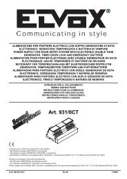
Da esterno parete<br />
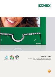
1) Inserire un cacciavite a taglio largo nella fessura ricavata nel lato inferiore<br />
del co<strong>per</strong>chio e con una semplice rotazione togliere <strong>il</strong> co<strong>per</strong>chio<br />
copriviti (Fig. 1).<br />
2) Togliere le 2 viti di fissaggio e <strong>il</strong> co<strong>per</strong>chio copri fotocellula.<br />
3) Fissare <strong>il</strong> contenitore della fotocellula in parete (Fig. 2), applic<strong>and</strong>o dei<br />
tasselli, cerc<strong>and</strong>o di ottenere l’allineamento migliore ut<strong>il</strong>izz<strong>and</strong>o le dime<br />
di fissaggio (vedi pag.7).<br />
4) Effettuare i collegamenti al corpo della fotocellula tenendo i f<strong>il</strong>i più corti<br />
possib<strong>il</strong>i (Fig. 3).<br />
Da colonnina<br />
1) Inserire un cacciavite a taglio largo nella fessura ricavata nel lato inferiore<br />
del co<strong>per</strong>chio e con una semplice rotazione togliere <strong>il</strong> co<strong>per</strong>chio<br />
copriviti (Fig. 1).<br />
2) Togliere le 2 viti di fissaggio e <strong>il</strong> co<strong>per</strong>chio copri fotocellula.<br />
3) Togliere <strong>il</strong> co<strong>per</strong>chio della colonnina inserendo un cacciavite a taglio<br />
largo nella fessura ricavata lateralmente (Fig. 4)<br />
4) Sf<strong>il</strong>are la parte frontale della colonnina (Fig. 5).<br />
5) Passare i conduttori ut<strong>il</strong>izz<strong>and</strong>o i due fori laterali del contenitore ed effettuare<br />
i collegamenti del corpo della fotocellula tenendo i f<strong>il</strong>i più corti<br />
possib<strong>il</strong>i (vedi Fig. 6 particolare A).<br />
6) Posizionare <strong>il</strong> contenitore della fotocellula in modo da sovrapporre <strong>il</strong> foro<br />
nella vite vedi (Fig. 6)<br />
Fissare <strong>il</strong> contenitore tramite le 3 viti date in dotazione con la colonnina.<br />
Photocell for surface wall-mounting or for column<br />
Description<br />
Surface wall-mount or column synchronized type photocell for protection of<br />
doors, gates <strong>and</strong> automated entries.<br />
It consists of: one modulated infrared ray receiver (RX) <strong>and</strong> one transmitter<br />
(TX), with selectable supply voltage <strong>and</strong> range.<br />
The external housing has a high resistance mechanic <strong>and</strong> to the atmospheric<br />
agents <strong>and</strong> its reduced dimensions ease the installation.<br />
NOTE: It is forbidden the use for reflection <strong>and</strong> the installation on non rigid<br />
surfaces, subject to vibrations.<br />
TECHNICAL FEATURES<br />
Technology: Direct TX-RX interpolation through infrared rays, modulated<br />
by impulses.<br />
Supply voltage:<br />
12V DC/AC with JP12 jum<strong>per</strong> inserted (10-18V A.C threshold)<br />
24V DC/AC without JP12 jum<strong>per</strong> (18-32V A.C threshold)<br />
Maximum absorption:<br />
at 12V: RX 46mA, TX (nom) 65mA, TX (sync) 37 mA<br />
at 24V: RX 55mA, TX (nom) 54mA, TX (sync) 45 mA<br />
Relay range: 1A at 24V DC/120V A.C.<br />
Answer dwell time:
Raccoordement de deux paires de cellules photoélectriques<br />
avec fonction de synchronisme<br />
Description<br />
Cellulle photoélectrique version synchronisée pour montage mural en sa<strong>il</strong>lie<br />
ou sur colonne pour la protection de portes, portaux, et entrées automatisées.<br />
Elle est <strong>com</strong>posée d’un récepteur (RX) et d’un transmetteur (TX) à rayons<br />
infrarouges modulés, avec tension d’alimentation et portée seletionnnables.<br />
Le boîtier externe a une élévée resistance mécanique et aux agents atmospheriques,<br />
et ses dimensions réduites rendent l’installation très simple.<br />
N.B. Il est interdit l’emploi par reflection et l’installation dans des surface<br />
non rigides sujetes à des vibrations.<br />
CARACTERISTIQUES TECHNIQUES<br />
Technologie: Interpolation directe TX-RX au moyen de rayons infrarouges<br />
modulés à impulses.<br />
Alimentation:<br />
12V c.c./c.a. avec pontage JP12 inseré (limites 10-18V c.a.)<br />
12V c.c./c.a. sans pontage JP12 (limites 18-32V c.a.)<br />
Absorption maximum:<br />
à 12V: RX 46mA, TX (nom.) 65mA, TX (sync) 37 mA<br />
à 24V: RX 55mA, TX (nom.) 54mA, TX (sync) 45 mA<br />
Portée relais: 1A à 24V c.c. / 120V c.a.<br />
Temps de réponse: < 30ms<br />
Angle de détection:<br />
RX ± 20° sans parabole et tube de réduction<br />
± 5° avec tube de réduction<br />
Angle rayon émi: TX: ±12°<br />
Température de fonctionnement: - 20° C ÷ 55° C<br />
Dégrée de protection IP 55<br />
Portée maximum: 15m<br />
N.B. La portée peut être réduite du 50% en présence de fenomèmes atmosphériques:<br />
brou<strong>il</strong>lard, pluie, poussière etc. et lorsque le tube de réduction<br />
de l’angle de réception (RX) est inséré.<br />
Dimensions: (LxHxP): 60x89x36 mm.<br />
INSTALLATION<br />
Pour <strong>per</strong>mettre un <strong>per</strong>fect alignement positionner le transmetteur (TX) et<br />
le récepteur (RX) en axe.<br />
Pour obtenir un optimum fonctionnement installer le récepteur (RX) du côté<br />
opposé aux rayons du sole<strong>il</strong> ou sources lumineuses.<br />
En insérant les tubes RX de réduction dans les photodiodes au lieu des<br />
paraboles on peut réduire l’effectif angle du rayon à ± 5°, en évitant ainsi<br />
les interférences du sole<strong>il</strong> et des sources lumineuses.<br />
Montage mural en sa<strong>il</strong>lie<br />
1) Insérer un tournevis large dans la fente dans le côté inférieur du couvercle<br />
et avec une rotation simple enlever le couvercle couvre-vis (Fig.<br />
1).<br />
2) Enlever les 2 vis de fixation et le couvercle couvre-cellules photoélectriques.<br />
3) Fixer le boîtier de la cellule photoélectrique dans la paroi (Fig. 2) en<br />
appliquant des goujons et en faisant attention au me<strong>il</strong>leur alignement<br />
en ut<strong>il</strong>isant les gabarit de <strong>per</strong>çage pour la fixation (voir page 7).<br />
4) Effectuer les raccordements au corps de la cellule photoélectrique en<br />
tenant les f<strong>il</strong>s les plus courts possible (Fig. 3).<br />
Montage sur la colonne<br />
1) Insérer un tournevis large dans la fente obtenue dans le côté inférieur<br />
du couvercle et avec une rotation simple enlever le couvercle couvre-vis<br />
(Fig. 1).<br />
2) Enlever les 2 vis de fixation et le couvercle couvre-cellules photoélectriques.<br />
3) Enlever le couvercle de la colonne en insérant un tournevis large dans<br />
la fente obtenue à un côté (Fig. 4).<br />
4) Déf<strong>il</strong>er la partie frontale de la colonne (Fig. 5).<br />
5) Passer le conducteurs en ut<strong>il</strong>isant les deus trous lateraux du boîtier et<br />
effectuer les raccordements du corps de la cellule photoélectrique en<br />
tenant les f<strong>il</strong>s les plus courts possible (voir Fig. 8, déta<strong>il</strong> A).<br />
6) Positionner le boîtier de la cellule photoélectrique afin de su<strong>per</strong>poser le<br />
trou à la vis (voir Fig. 6)<br />
Fixer le boîtier au moyen des 3 vis fournies avec la colonne.<br />
Anschluss von zwei synchronisierten Photozellenpaaren<br />
Beschreibung<br />
Synchronisierte Version der Photozellen für Aufputz-Montage oder Montage<br />
an der Säule für den Schutz von: Türen, Toren und automatisierten<br />
Eingängen. Bestehend aus: einem Empfänger (RX) und einem Sender<br />
(TX), mit modulierten infraroten Strahlen, mit wählbarer Versorgungsspannung<br />
und Sendebereich.<br />
Das Gehäuse ist resistent gegen hohe mechanische Beanspruchung und<br />
gegen atmosphärische Einflüsse, und seine reduzierten Abmessungen vereinfachen<br />
die <strong>Installation</strong>.<br />
Hinweis: Die Montage an reflektierenden, weichen Oberflächen, und auf<br />
Flächen die Vibrationen ausgesetzt sind, ist nicht erlaubt.<br />
TECHNISCHE DATEN<br />
Technologie: direkte TX-RX Interpolation durch impulsmodulierte Infrarot-Strahlen<br />
Versorgungsspannng: 12V DC/AC mit eingesteckter Brücke JP12 (10-18V<br />
AC )<br />
24 V DC/AC ohne Brücke JP12 (18-32V AC)<br />
Maximale Stromaufnahme:<br />
bei 12V: RX 46mA, TX (nom.) 65 mA, TX (Sync) 37 mA<br />
bei 24V: RX 55mA, TX (nom.) 54 mA, TX (Sync) 45 mA<br />
Relaisbelastung: 1A bei 24VDC/120VAC<br />
Ansprechzeit: < 30ms Erfassungswinkel:<br />
Erfassungswinkel :<br />
RX ± 20° ohne Parabol und Reduktionsrohr<br />
± 5° mit Reduktionsrohr<br />
Gesendeter Abstrahlwinkel: TX: ±12°<br />
Betriebstem<strong>per</strong>atur: - 20° ÷ + 55° C<br />
Schutzart: IP55<br />
Maximaler Sendebereich: 15m<br />
N.B. Der Sendebereich kann durch atmosphärische Einflüsse reduziert<br />
werden: Nebel, Regen, Staub usw. und wenn das Reduktionsrohr des<br />
Empfangswinkels eingesetzt wird. Abmessungen (BxHxT): 60x89x36 mm.<br />
INSTALLATION:<br />
Für eine <strong>per</strong>fekt Ausrichtung den Sender (TX) und den Empfänger (RX) in<br />
Achse stellen. Um einen optimalen Betrieb zu erreichen, den Empfänger<br />
(RX) abgew<strong>and</strong>t von Sonnenlicht oder <strong>and</strong>eren Lichtquellen einbauen.<br />
Durch Einsetzen der Reduktionsrohre in die Photodioden anstelle der Parabole,<br />
kann der wirksame Abstrahlwinkel um ± 5° vermindert werden. Auf<br />
diese Weise kann der Einfluss von Sonnenstrahlen und <strong>and</strong>eren Lichtquellen<br />
vermieden werden.<br />
AP-Montage<br />
1) Einen Schraubenzieher mit breiter Klinge in den Schlitz auf der Unterseite<br />
des Deckels einstecken und mit einer einfachen Drehung die<br />
Schraubenabdeckung abnehmen (Fig. 1).<br />
2) Die 2 Befestigungsschrauben entfernen und die Photozellenabdeckung<br />
abnehmen.<br />
3) Das Gehäuse unter Verwendung der mitgelieferten Düpbel an der W<strong>and</strong><br />
montieren (Abb. 2), und unter Verwendung der Bohrschablonen auf Seite<br />
7, die bestmögliche Ausrichtung erreichen.<br />
4) Die Drähte an die Photozelle anschließen und dabei so kurz wie möglich<br />
halten (Fig. 3).<br />
Montage an der Säule<br />
1) Einen Schraubenzieher mit breiter Klinge in den Schlitz auf der Unterseite<br />
des Deckels einstecken und mit einer einfachen Drehung die<br />
Schraubenabdeckung abnehmen (Fig. 1).<br />
2) Die 2 Befestigungsschrauben entfernen und die Photozellenabdeckung<br />
abnehmen.<br />
3) Den Deckel der Säule durch Einsetzen eines Schraubeziehers mit breiter<br />
Klinge in die Seitenschlitze, abnehmen (Abb. 4).<br />
4) Den Frontte<strong>il</strong> der Säule nach oben ziehen (Abb. 5).<br />
5) Die Kabel durch die 2 Seitenlöcher des Gehäuses führen und die Drähte<br />
an die Photozelle anschließen und dabei so kurz wie möglich halten<br />
(siehe Abb. 6, deta<strong>il</strong> A).<br />
6) Das Photozellengehäuse so ausrichten, dass das Loch mit der Schraube<br />
vollkommen übereinstimmt (siehe Abb. 6). Das Gehäuse mit den 3 bei<br />
der Säule mitgelieferten Schrauben befestigen.<br />
FR<br />
DE<br />
1
Célula para montaje de su<strong>per</strong>ficie o en la columna<br />
Descripción<br />
Fotocélula versión sincronizada para montaje de suo<strong>per</strong>ficie o en la columna<br />
para la protección de puertas, rejas y entradas automatizadas.<br />
Consiste de un receptor (RX) y de un transmetidor (TX) a rayos infrarrojos<br />
modulados, con tensión de alimentación y alcance seleccionables. En contenedor<br />
externo tiene una elevada resistencia mecánica y a los agentes<br />
atmosféricos, y sus reducidas dimensiones fac<strong>il</strong>itan la instalación.<br />
N.B. Se prohibe el uso para la reflexión y la instalación en su<strong>per</strong>ficies no<br />
rígidas sujetas a vibraciones.<br />
CARACTERÍSTICAS<br />
Tecnología: Interpolación directa TX-RX por medioo de rayous infrarrojos<br />
modullados a impulsos.<br />
Alimentación:<br />
12V cc/ac con puente JP12 insertado (límites 10-18V a.c.)<br />
24V c.c./c.a. sin puente JP 12 insertado (límites 18/32V ca)<br />
Absorción máxima:<br />
a 12V: RX 46mA, TX (nom) 65 mA, TX (sync) 37 mA<br />
a 24V: RX 55mA, TX (nom) 54mA, TX (sync) 45 mA<br />
Alcance relé: 1A a 24V cc/120C c.a.<br />
Tiempo de respuesta: < 30ms<br />
Angulo de detección:<br />
RX ± 20° sin parábola y tubo de reducción<br />
± 5 con tubo de reducción<br />
Ángulo rayo emitido TX: ±12°<br />
Tem<strong>per</strong>atura de funcionamiento: - 20° C ÷ + 55° C<br />
Grado de protección IP 55<br />
Alcance máximo: 15m<br />
N.B. El alcance se puede reducir del 50% en presencia de fenómenos atmosféricos:<br />
niebla, lluvia, polvo etc. y cu<strong>and</strong>o se inserta el tubo di reducción<br />
del ángulo de recepción (RX).<br />
Dimensiones (LxHxP): 60x89x36 mm.<br />
INSTALACIÓN<br />
Para <strong>per</strong>mitir un <strong>per</strong>fecto alineamiento posicionar el transmetitdor (TX) y<br />
el receptor (RX) en eje. Para obtener un funcionamento optimal instalar el<br />
receptor (RX) en el lado opuesto a los rayos del sol o fuentes luminosas.<br />
Insert<strong>and</strong>o los tubos RX de reducción en los fotodiodos en lugar de las<br />
parábolas se puede reducir el efectivo ángulo del rayo a ± 5°, evit<strong>and</strong>o así<br />
las interferencias del sol y de las fuentes luminosas.<br />
Montaje de su<strong>per</strong>ficie<br />
1) Insertar un destorn<strong>il</strong>lador con tajo ancho en la a<strong>per</strong>tura obtenida en<br />
el lado inferior de la tapa y con una simple rotación quitar la tapa cubre-torn<strong>il</strong>los<br />
(Fig. 1).<br />
2) Quitar los 2 torn<strong>il</strong>los de fijación y la tapa cubre-fotocélula.<br />
3) Fijar el contenedor de la fotocélula a la pared (Fig. 2) aplic<strong>and</strong>o los<br />
tacos y intent<strong>and</strong>o de obtener el mejor alineamiento, ut<strong>il</strong>iz<strong>and</strong>o los dechados<br />
de fijación (ver pag.7).<br />
4) Efetuar los conexionados al cuerpo de la fotocélula teniendo los h<strong>il</strong>os<br />
los más cortos posible (Fig. 3).<br />
Fotocélula para montagem saliente o para coluna<br />
Descrição<br />
Fotocélula versão sincronizada para montagem saliente ou para coluna para<br />
proteção de portas, portões e entradas automatizadas.Está <strong>com</strong>posta de um<br />
receptor (RX) e um transmetidor (TX) a raios de infravermelhos modulados,<br />
<strong>com</strong> tensão de alimentação e alcance selecionáveis. O contentor externo<br />
tem uma elevada resistência mecánica e aos agentes atmosféricos, e a suas<br />
dimensões reduzidas fac<strong>il</strong>itam a instalação.<br />
N.B. Se prohibe o uso por reflexão e a instalação em su<strong>per</strong>ficies não rígidas<br />
sujeitas às vibrações.<br />
CARACTERÍSTICAS TÉCNICAS<br />
Tecnología: Interpolação directa TX-RX através de raios infravermelhos<br />
modulados a impulsos.<br />
Alimentação:<br />
12V cc/ac <strong>com</strong> ponte JP12 inserido (límites 10-18V a.c.)<br />
24V c.c./c.a. sem ponte JP 12 inserido (límites 18/32V ca)<br />
Absorção máxima:<br />
a 12V: RX 46mA, TX (nom) 65 mA, TX (sync) 37 mA<br />
a 24V: RX 55mA, TX (nom) 54mA, TX (sync) 45 mA<br />
Alcance relé: 1A a 24V cc/120V c.a.<br />
Tempo de resposta: < 30ms<br />
Angulo de deteção:<br />
RX ± 20° sem parábola e tubo de redução<br />
± 5 <strong>com</strong> tubo de redução<br />
Ángulo do raio emitido TX: ±12°<br />
Tem<strong>per</strong>atura de funcionamento: - 20° C ÷ + 55° C<br />
Grado de proteção IP 55<br />
Alcance máximo: 15m<br />
N.B. O alcance pode-se reduzir do 50% em presência de fenómenos atmosféricos:<br />
nevoeiro, chuva, pó etc. e e qu<strong>and</strong>o se inserir o tubo de redução<br />
do ángulo de recepção (RX) de ± 5°.<br />
Dimensões (LxHxP): 60x89x36 mm.<br />
INSTALAÇÃO<br />
Para <strong>per</strong>mitir um <strong>per</strong>feito alinhamento posicionar o transmetidor (TX) e o<br />
receptor (RX) em eixo.<br />
Par obter un funcionamento optimal instalar o receptor (RX) na parte oposta<br />
aos raios solares e às fontes luminosas.<br />
Inserindo os tubos RX de reducção nos fotodiodos em lugar das parábolas<br />
pode-se reduzir o efectivo ángulo do raio a ± 5°, evit<strong>and</strong>o assim as interferências<br />
do sol e das fontes luminosas.<br />
Montagem saliente<br />
1) Inserir uma chave de parafusos <strong>com</strong> talho largo na fenta obtida no lado<br />
inferior da tampa e <strong>com</strong> uma simples rotação retirar a tampa cobre-parafusos<br />
(Fig. 1).<br />
2) Retirar os 2 parafusos de fixação e a tampa cobre-fotocélulas.<br />
3) Fixar o contentor da fotocélula na parede (Fig. 2) aplic<strong>and</strong>o as calhas e<br />
fazendo o possível para obter o melhor alinhamento, ut<strong>il</strong>iz<strong>and</strong>o os furos<br />
de fixação (ver pag.7).<br />
4) Efetuar as ligações ao corpo da fotocélula tendo os fíos os mais curtos<br />
possível (Fig. 3).<br />
Montaje a la columna<br />
1) Insertar un destorn<strong>il</strong>lador con tajo ancho en la a<strong>per</strong>tura obtenida en<br />
el lado inferior de la tapa y con una simple rotación quitar la tapa cubre-torn<strong>il</strong>los<br />
(Fig. 1).<br />
2) Quitar los 2 torn<strong>il</strong>los de fijación y la tapa cubre-fotocélula.<br />
3) Quitar la tapa de la columna insert<strong>and</strong>o un destorn<strong>il</strong>lador con tajo<br />
ancho en la a<strong>per</strong>tura obtenida lateralmente (Fig. 5).<br />
4) Desf<strong>il</strong>ar la parte frontal de la columna (Fig. 6).<br />
5) Pasar los conductores ut<strong>il</strong>iz<strong>and</strong>o los dos orificios laterales del contenedor<br />
y efectuar los conexionados del cuerpo de la fotocélula teniendo<br />
los h<strong>il</strong>os los más cortos posible (ver Fig. 7, particular A).<br />
6) Posicionar el contenedor de la fotocélula de manera que el orificio sea<br />
sobrepuesto al torn<strong>il</strong>lo (Fig. 7).<br />
Fijar el contenedor por medio de los 3 torn<strong>il</strong>los suministrados con la<br />
columna.<br />
Montagem na colona<br />
1) Inserir uma chave de parafusos <strong>com</strong> talho largo na fenta obtida no lado<br />
inferior da tampa e <strong>com</strong> uma simples rotação retirar a tampa cobre-parafusos<br />
(Fig. 1).<br />
2) Retirar os 2 parafusos de fixação e a tampa cobre-fotocélulas.<br />
3) Retirar a tampa da colona inserindo uma chave de parafusos <strong>com</strong> talho<br />
largo na fenta obtida lateralmente (Fig. 5)<br />
4) Desenfiar a parte frontal da colona (Fig. 6).<br />
5) Passar os condutores ut<strong>il</strong>iz<strong>and</strong>o os dois furos do contentor e efetuar as<br />
ligações do corpo da fotocélula tendo os furos os mais curtos possível<br />
(ver Fig. 7, pormenor A).<br />
6) Posicionar o contentor da fotocélula de modo a sobrepôr o furo ao parafuso<br />
(Fig. 7)<br />
Fixar o contentor através dos 3 parafusos fornecidos <strong>com</strong> a colona.<br />
2<br />
ES<br />
PT
60<br />
mm<br />
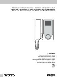
Fig. 1<br />
Inserire <strong>il</strong> cacciavite<br />
Insert screwdriver<br />
Insérer le tournevis<br />
Schraubenzieher einsetzen<br />
Insertar el destorn<strong>il</strong>lador<br />
Inserir a chave de parafusos<br />
Fig. 2<br />
400÷600<br />
mm<br />
39<br />
mm<br />
Fig. 3<br />
Fig. 5<br />
Fig. 6<br />
Fig. 4<br />
A<br />
3
COLLEGAMENTI<br />
1) Selezionare l’alimentazione della fotocellula agendo sul ponticello<br />
JP12V di selezione della tensione.<br />
La scelta 12/24 Vcc/ca va fatta in base alla tensione disponib<strong>il</strong>e della<br />
centralina<br />
JP 12 con ponticello inserito=Alimentazione 12Vc.c./c.a.<br />
JP 12 senza <strong>il</strong> ponticello=Alimentazione 24Vc.c./c.a.<br />
2) Nel caso di due trasmettitori (TX) vicini, <strong>il</strong> raggio di uno potrebbe interferire<br />
sull’altro ricevitore non garantendo <strong>il</strong> corretto funzionamento.<br />
Per ovviare questo problema, se disponib<strong>il</strong>e l’alimentazione in corrente<br />
alternata, è possib<strong>il</strong>e ut<strong>il</strong>izzare <strong>il</strong> sistema di sincronismo che <strong>per</strong>mette<br />
di far funzionare alternativamente le due coppie di fotocellule. Per attivare<br />
la funzione di sincronismo si deve togliere <strong>il</strong> ponticello, sync, del<br />
trasmettitore (TX).<br />
Ponticello “sync” inserito = funzionamento normale<br />
Ponticello “sync” non inserito = funzione sincronismo<br />
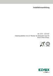
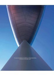
3) Eseguire i collegamenti elettrici in base alla funzione richiesta, secondo<br />
quanto riportato nelle caratteristiche tecniche, (Fig. 7).<br />
Il led bicolore presente nel ricevitore consente di ottenere una verifica<br />
dell’allineamento corretto tra RX e TX.<br />
N.B. L’allineamento deve essere particolarmente preciso qu<strong>and</strong>o viene<br />
inserito <strong>il</strong> tubicino <strong>per</strong> la riduzione dell’effetto angolo del raggio a ±5°.<br />
LED<br />
Significato<br />
Spento<br />
Alimentazione assente<br />
Rosso<br />
Presenza ostacolo, allineamento errato<br />
Lampeggiante Allineamento non <strong>per</strong>fetto<br />
Verde<br />
Allineamento ottimale<br />
4) Eseguita l’installazione della fotocellula. Controllare <strong>il</strong> funzionamento interrompendo<br />
più volte <strong>il</strong> fascio (raggio infrarosso); verificare l’accensione<br />
del led rosso della centralina e la <strong>com</strong>mutazione del relè.<br />
5) Eseguito <strong>il</strong> collaudo posizionare <strong>il</strong> frontalino ut<strong>il</strong>izz<strong>and</strong>o le 2 viti di fissaggio<br />
ed inserire la mostrina copri-viti.<br />
CONNECTIONS:<br />
1) Select the photocell supply voltage by o<strong>per</strong>ating on the jum<strong>per</strong> JP12V<br />
for the supply voltage selection.<br />
The 12/24V DC/AC choice must be made according to the voltage ava<strong>il</strong>able<br />
in the control unit.<br />
JP 12 with jum<strong>per</strong> inserted = 12V DC/AC supply voltage<br />
JP 12 without jum<strong>per</strong> = 24V DC/AC supply voltage<br />
2) If the two transmitters (TX) are installed one close to the other, the ray<br />
of one could interfere with the ray of the other. in this case the correct<br />
o<strong>per</strong>ation cannot be guaranteed. To avoid this problem, if the alternated<br />
current supply voltage is ava<strong>il</strong>able, it is possible to use the synchronism<br />
system which allows the two pairs of photocells to o<strong>per</strong>ate alternatively.<br />
To activate the synchronism function remove the “sync” jum<strong>per</strong> on the<br />
transmitter (TX).<br />
Jum<strong>per</strong> “sync” inserted = normal o<strong>per</strong>ation<br />
Jum<strong>per</strong> “sync” not inserted = synchronism function<br />
3) Carry out the electrical connection according to the required function,<br />
as <strong>per</strong> the technical features (see Fig. 7).<br />
The bicolour LED present on the receiver allows you to verify the correct<br />
aligning between the RX <strong>and</strong> TX.<br />
NOTE: The aligning must be particularly precise when inserting the tube<br />
for the reduction of the ray angle effect to ± 5°.<br />
LEd<br />
Switched off<br />
Red<br />
Flashing light<br />
Green<br />
Meaning<br />
No supply voltage<br />
Presence of obstacle, wrong aligning<br />
Wrong aligning<br />
Perfect aligning<br />
4) Once the photocell installation has been carried out, check the o<strong>per</strong>ation<br />
interrupting several time the beam (infrared ray);<br />
Check the central unit red LED lighting <strong>and</strong> the relay switching.<br />
5) Once the final check up has been ac<strong>com</strong>plish, position the front part<br />
using the 2 fixing screws <strong>and</strong> insert the screw cover.<br />
4<br />
I<br />
EN
RACCORDEMENTS<br />
1) Selectionner l’alimentation de la cellule photoélectrique en agissant sur<br />
le pontage JP12V de selection de la tension. Le choix 12/24V c.c./c.a.<br />
doit être fait selon la tension disponible de la centrale<br />
JP 12 avec pontage inséré = alimentation 12V c.c./c.a.<br />
JP 12 sans le pontage = alimentation 24V c.c./c.a.<br />
2) Si les deux transmetteur (TX) ont été installés l’un près de l’autre, le<br />
rayon de l’un pourrait interférer avec l’ autre récepteur en n’assurant pas<br />
le correct fonctionnement. Pour éviter ce problème, si l’alimentation est<br />
en courant alterné, <strong>il</strong> est possible d’ut<strong>il</strong>iser le système de synchronisme<br />
qui <strong>per</strong>met le fonctionnement alternatif des deux paires de cellule photoélectriques.<br />
Pour activer la fonction de synchronisme on doit enlever<br />
le pontage “sync” du transmetteur (TX).<br />
Pontage “sync” inséré = fonctionnement normal<br />
Pontage “sync” non inséré = fonction synchronism<br />
3) Efectuer les raccordements électriques selon la fonction requise et<br />
selon les indications des caractéristiques techniques (Fig. 7).<br />
La LED bicolore présente sur le récepteur <strong>per</strong>met d’obtenir un contrôle<br />
de l’alignement correct entre RX et TX.<br />
N.B.L’alignement doit être particulierment précis lorsque le tube est inséré<br />
pour la réduction de l’effet angle du rayon à ± 5°.<br />
LED<br />
Éteint<br />
Rouge<br />
Lampe cignotante<br />
Signification<br />
Alimentation absente<br />
Pésence obstacle, alignement erroné<br />
Alignement non <strong>per</strong>fect<br />
4) L’installation de la cellule photoélectrique effectuée, contrôler le fonctionnement<br />
en interrompant plusieurs foix le faiseau (rayon infrarouge).<br />
5) L’essai final effectué, positionner la partie frontale en ut<strong>il</strong>isant le 2 vis<br />
de fixation et insérer le couvre-vis.<br />
CONEXIONADOS<br />
1) Seleccionar la alimentación de la fotocélula actu<strong>and</strong>o sobre el puente<br />
JP12V de selección de la tensión. La elección 12/24 Vc.c./c.a. ha de<br />
ser hecha en base a la tensión disponible en la central.<br />
JP 12 con puente insertado = Alimentación 12V c.c./c.a.<br />
JP 12 sin puente = Alimentación 24V c.c./c.a.<br />
2) Si se instalan dos transmetidores (TX) cercanos, el rayo de uno podría<br />
interferir con el otro receptor no pudiendo así asegurar el <strong>per</strong>fecto<br />
funcionamiento. Para obviar este poblema, si se dispone de corriente<br />
altenra, es posibe ut<strong>il</strong>izar el sistema de sincronismo que <strong>per</strong>mite hacer<br />
funcionar alternativamente los dos pares de fotocélulas. Para activar<br />
la función de sincronismo sacar el puente “sync” del transmetidor (TX).<br />
Puente “sync” insertado = funcionamiento normal<br />
Puente “sync” no insertado = función sincronismo<br />
3) Efectuar los conexionados eléctricos en base a la función requerida y<br />
según lo que indican las características técnica (Fig. 7).<br />
El led bicolor presente en los receptores <strong>per</strong>mite obtener una verificación<br />
del alineamiento correcto entre RX y TX<br />
N.B. El alineamiento debe ser particolarmente preciso cu<strong>and</strong>o viene<br />
insertado el tubo para la reducción del efecto del ángulo del rayo a ± 5°.<br />
LED<br />
Apagado<br />
Rojo<br />
Relampagueador<br />
Verde<br />
Significado<br />
Alimentador absente<br />
Presencia obstáculo, alineamiento erróneo<br />
Alineamiento non <strong>per</strong>fecto<br />
Alineamientooptimal.<br />
4) Efectuada la instalación de la fotocélula controlar el funcionamiento<br />
interrumpiendo más veces el haz (rayo infrarojo). Verificar el encendido<br />
del led rojo de la central y la conmutación del relé.<br />
5) Efectuada la prueba final posicionar la parte frontal ut<strong>il</strong>iz<strong>and</strong>o los 2<br />
torn<strong>il</strong>los de fixación e insert<strong>and</strong>o el cubre-torn<strong>il</strong>los.<br />
ANSCHLÜSSE<br />
1) Wählen Sie die Photozellversorgungsspannung mittels der Brücke<br />
JP12. Je nach gelieferter Spannung von der Steuereinheit 12 oder<br />
24VDC/AC wählen.<br />
JP 12 mit Brücke eingesetzt = 12VDC/AC Versorgungsspannung.<br />
JP 12 ohne Brücke = 24VDC/AC Versorgungsspannung<br />
2) Sind zwei Sender(TX) nah beiein<strong>and</strong>er montiert, könnte der Strahl<br />
eines Empfängers mit dem des <strong>and</strong>eren Empfängers interferieren; in<br />
diesem Fall kann ein korrekter Betrieb nicht gewährleistet werden. Um<br />
dieses Problem zu verhindern, und wenn für die Versorgung der Geräte<br />
eine Wechselspannung verfügbar ist, ist es möglich das Synchronisierungssystem,<br />
das den abwechselnden Betrieb der zwei Photozellpaare<br />
ermöglicht, zu nutzen. Um die Synchronisierungsfunktion zu<br />
aktivieren, die Brücke “Sync” des Senders (TX) abnehmen.<br />
Brücke “sync” eingesetzt = Normalbetrieb Brücke “sync” nicht eingesetzt<br />
= Synchronisierungsfunktion<br />
Brücke “sync” eingesetzt = Normalbetrieb<br />
Brücke “sync” nicht eingesetzt = Synchronisierungsfunktion<br />
3) Die elektrischen Anschlüsse gemäss der geforderten Funktion und den<br />
technischen Daten durchführen (Fig. 7). Die zweifarbige LED beim Empfänger<br />
ermöglicht eine Überprüfung der korrekten Ausrichtung von<br />
RX und TX.<br />
Hinweis: Die Ausrichtung muss besonders genau sein, wenn das<br />
Reduktionsrohr für den Abstrahlwinkels eingesetzt wird.<br />
LED Bedeutung Ausgeschaltet Keine Versorgungsspannung<br />
Rot Anwesenheit eines Hindernisses, falsche Ausrichtung<br />
BlinklichtAusrichtung nicht exakt Grün Ausrichtung optimal<br />
4) Wenn die <strong>Installation</strong> der Photozelle durchgeführt wurde, den Betrieb<br />
durch mehrfaches Unterbrechen des Richtstrahls (infraroter Strahl) überprüfen.<br />
Das Einschalten der roten LED in der Steuerzentrale und die<br />
Aktivierung des Relais überprüfen .<br />
5) Ist die endgültige Prüfung abgeschlossen, den Frontte<strong>il</strong> mit den 2 Befestigungsschrauben<br />
fixieren und die Schraubenabdeckung einsetzen.<br />
LIGAÇÕES<br />
1) Selecionar a alimentação das fotocélulas obr<strong>and</strong>o na ponte JP12V de<br />
seleção da tensão. A escolha 12/24 Vc.c./c.a. deve ser feita conforme<br />
à tensão disponível na central.<br />
JP 12 <strong>com</strong> ponte inserida = Alimentação 12V c.c./c.a.<br />
JP 12 sem ponte = Alimentação 24V c.c./c.a.<br />
2) No caso de dois transmetidores (TX) vezinhos, o raio de um deles<br />
podería interferir <strong>com</strong> o outro não assegur<strong>and</strong>o assim o correcto funcionamento.<br />
Para evitar este problema, se fôr disponível a alimentação<br />
em corrente alternada, é possível ut<strong>il</strong>izar o sistema de sincronismo<br />
que <strong>per</strong>mite de fazer funcionar alternativamente os dois pares de fotocélulas.<br />
Para activar a função de sincronismo retirar a ponte “sync”<br />
do transmetidor (TX).<br />
Ponte “sync” inserida = funcionamento normal<br />
Ponte “sync” não inserida = função sincronismo<br />
3) Efectuar as ligações eléctricas em base à função pretendida e conforme<br />
a quanto indicado nas características técnicas (Fig. 7).<br />
O led bicolor presente no receptor <strong>per</strong>mite obter uma verificação do<br />
alinhamentocorrecto entre RX e TX<br />
N.B. O alinhamento deve ser particularmente exacto qu<strong>and</strong>o insere-se<br />
o tubo para a redução do efecto do ángulo do raio a ± 5°.<br />
LED<br />
Desligado<br />
Vermelho<br />
Indicador cint<strong>il</strong>ante<br />
Verde<br />
Significado<br />
Alimentação ausente<br />
Presência dum obstáculo, alinhamento erróneo<br />
Alinhamento não <strong>per</strong>feito<br />
Alinhamento optimal<br />
4) Efetuada a instalação da fotocélula, controlar o funcionamento interrompendo<br />
mais vezes o feixe (raio infravernelho). Verificar o acendimento<br />
do led vermelho da central e a <strong>com</strong>utação do relé.<br />
5) Executada a verificação e a aprovação posicionar a parte frontal ut<strong>il</strong>iz<strong>and</strong>o<br />
os 2 parafusos e inserir o cobre-parafusos.<br />
FR<br />
DE<br />
ES<br />
PT<br />
5
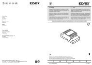
RX<br />
TX<br />
Fig. 7<br />
JP 12 (12-24V)<br />
JP 1 (+15 m)<br />
JP 12 (12-24V)<br />
“SYNC”<br />
12/24 V.c.c./c.a.<br />
+ -<br />
N.A.<br />
N.C.<br />
COM<br />
+ -<br />
12/24 V.c.c./c.a.<br />
COLLEGAMENTO DI DUE COPPIE DI FOTOCELLULE<br />
CONNECTION OF A 2-PAIR OF PHOTOELECTRIC CELLS<br />
CONNEXION DE DEUX PAIRES DE CELLULES PHOTOéLECTRIQUES<br />
ANSCHLUSS VON 2 FOTOZELLEN-PAAREN<br />
Conexionado de una pareja de fotocélulas<br />
LIGAÇÃO DE DOIS PARES DE FOTOCéLULAS<br />
12/24V c.c./c.a.<br />
COMUNE, COMMON, COMMUN, GEMEINSAM, Común<br />
contatto n.c., N.C. CONTACT, CONTACT N.F.<br />
ÖFFNERKONTAKT, CONTACTO N.C., CONTACTO N.F.<br />
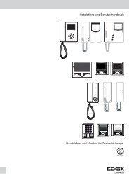
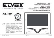
Dima di foratura<br />
Dr<strong>il</strong>lingsheme<br />
Gabarit de <strong>per</strong>çage<br />
Borrschablone<br />
Guia para horadar<br />
Guia para furar<br />
Ø 5mm<br />
Cod. S6I.FOT.DIM<br />
UP<br />
ALTO<br />
Dima di foratura<br />
Dr<strong>il</strong>lingsheme<br />
Gabarit de <strong>per</strong>çage<br />
Borrschablone<br />
Guia para horadar<br />
Guia para furar<br />
Ø 5mm<br />
Cod. S6I.FOT.DIM<br />
UP<br />
ALTO<br />
Ø 5mm<br />
Ø 5mm<br />
Ø 5mm<br />
Ø 5mm<br />
6<br />
Dima di foratura<br />
Cod. S6I.FOT.DIM<br />
Dima di foratura<br />
Cod. I S6I.FOT.DIM<br />
EN FR<br />
DE<br />
ES<br />
PT
COLLEGAMENTO DI DUE COPPIE DI FOTOCELLULE ALLA CENTRALINA<br />
FOTOCELLULA ESTERNA (1): funzionamento in chiusura FOTOCELLULA INTERNA (2): funzionamento in a<strong>per</strong>tura/chiusura<br />
CONNECTION OF A 2-PAIR OF PHOTOELECTRIC CELLS TO THE CENTRAL UNIT<br />
EXTERNAL PHOTOCELL (1): O<strong>per</strong>ation during the closing phase - INTERNAL PHOTOCELL (2): O<strong>per</strong>ation during the opening/closing phase.<br />
RACCORDEMENT DE DEUX JEUX DE CELLULES PHOTOéLECTRIQUES à LA CENTRALE DE CONTROLE<br />
CELLULE PHOTOELECTRIQUE EXTERNE (1): Fonctionnement en ferméture<br />
CELLULE PHOTOELECTRIQUE INTERNE (2): fonctionnement en ouverture/ferméture<br />
ANSCHLUSS VON 2 FOTOZELLEN-PAAREN AN ZENTRALE<br />
EXTERNE PHOTOZELLE (1): Betrieb beim Schließen - INTERNE PHOTOZELLE (2): Betrieb beim Öffnen/Schließen<br />
Conexionado de una pareja de fotocélulas A LA CENTRAL<br />
FOTOCELULA EXTERNA (1): Funcionamiento en cierre - FOTOCELULA INTERNA (2): Funcionamiento en a<strong>per</strong>tura/cierre<br />
LIGAÇÃO DE DOIS PARES DE FOTOCéLULAS à CENTRAL<br />
FOTOCELULA EXTERNA (1): Funcionamento no fechar - FOTOCELULA INTERNA (2): Funcionamento no abrir/fechar<br />
Alla centralina - To control unit - A la centrale<br />
Zur Steuerungseinheit - A la central<br />
12/24 Vdc<br />
ST.PA./FCOS<br />
FOT<br />
COM1<br />
Collegamento di due coppie di fotocellule con funzione di sincronismo<br />
Connection of two photocell pairs with synchronism function<br />
Cellule photoélectrique pour montage mural en sa<strong>il</strong>lie ou sur colonne<br />
Anschluss von zwei Photozellenpaaren mit Synchronisierungsfunktion<br />
Conexionado de dos pares de fotocélulas con función de sincronismo<br />
Ligação de dois pares de fotocélulas <strong>com</strong> função de sincronismo.<br />
Alla centralina - To control unit - A la centrale<br />
Zur Steuerungseinheit - A la central<br />
12/24 Vac<br />
ST.PA./FCOS<br />
FOT<br />
COM1<br />
Riproduzione vietata anche parziale. La società ELVOX s.p.a. tutela i diritti sui propri elaborati a termine di Legge.<br />
Reproduction forbidden, even partial. ELVOX S.P.A. guards its own rights according to the law.<br />
Réproduction défendu, même partiale. La Société ELVOX S.P.A. defende ses droits selon la loi.<br />
Nachdruck (auch partial) verboten. Alle Rechte an der technischen Dokumentation bei der ELVOX AG.<br />
Reproducción prohibida también parcial. ELVOX s.p.a. defiende sus derechos según la ley.<br />
Reprodução proibida mesmo parcial. A sociedade ELVOX s.p.a. tem os seus direitos registados e protegidos nos<br />
termos da Lei.<br />
I<br />
EN<br />
FR<br />
DE<br />
ES<br />
PT<br />
7
Vimar SpA: Viale Vicenza, 14<br />
36063 Marostica VI - Italy<br />
Tel. +39 0424 488 600 - Fax (Italia) 0424 488 188<br />
Fax (Export) 0424 488 709<br />
www.vimar.<strong>com</strong><br />
S6I.EF0.4S0 03 13 11<br />
VIMAR - Marostica - Italy