Sistema di tubazioni preisolate flessibili per ... - Watts Industries
Sistema di tubazioni preisolate flessibili per ... - Watts Industries
Sistema di tubazioni preisolate flessibili per ... - Watts Industries

Create successful ePaper yourself
Turn your PDF publications into a flip-book with our unique Google optimized e-Paper software.
<strong>Sistema</strong> <strong>di</strong> <strong>tubazioni</strong> <strong>preisolate</strong><br />
<strong>flessibili</strong> <strong>per</strong> teleriscaldamento<br />
Caratteristiche principali<br />
Il sistema <strong>di</strong> <strong>tubazioni</strong> <strong>preisolate</strong> termicamente<br />
Microflex sono idonee all’uso <strong>per</strong> :<br />
- Riscaldamento<br />
- Teleriscaldamento<br />
- Acqua sanitaria<br />
- Applicazioni speciali<br />
- Microflex ® è <strong>di</strong>sponibile in <strong>tubazioni</strong> singole,<br />
doppie o quadruple.<br />
- Tubo principale in PEX-a dotato <strong>di</strong> barriera<br />
contro la <strong>di</strong>ffusione dell’ossigeno.<br />
- L’isolante dalla struttura compatta e la guaina<br />
<strong>di</strong> tipo corrugato rendono il tubo flessibile,<br />
assicurando una posa semplice e rapida dei<br />
tubi.
TUBAZIONI PREISOLATE MICROFLEX<br />
INDICE<br />
2<br />
DESCRIZIONE DEL SISTEMA pag. 4<br />
Campi <strong>di</strong> applicazione .................................................................................................................................. pag. 4<br />
Proprietà Microflex ...................................................................................................................................... pag. 4<br />
Raggio <strong>di</strong> curvatura ...................................................................................................................................... pag. 4<br />
Struttura del sistema Microflex ......................................................................................................................pag. 4<br />
Tubo principale in PEX-a.............................................................................................................................. pag. 5<br />
Resistenza chimica........................................................................................................................................pag. 5<br />
Barriera alla <strong>di</strong>ffusione dell’ossigeno ............................................................................................................ pag. 7<br />
Comportamento a lungo termine ..................................................................................................................pag. 7<br />
Materiale isolante ........................................................................................................................................ pag. 8<br />
Guaina in HDPE corrugato ............................................................................................................................pag. 8<br />
Dimensioni bobine........................................................................................................................................ pag. 9<br />
GAMMA DI PRODOTTI pag. 10<br />
Riscaldamento centralizzato ...................................................................................................................... pag. 10<br />
Riscaldamento centralizzato e impianti sanitari.......................................................................................... pag. 11<br />
Impianti sanitari .......................................................................................................................................... pag. 11<br />
Microflex Cool con e senza cavo scaldante autoregolante..........................................................................pag. 12<br />
Accessori.................................................................................................................................................... pag. 17<br />
Raccor<strong>di</strong> terminali Jentro ............................................................................................................................pag. 22<br />
ISTRUZIONI DI INSTALLAZIONE TUBAZIONI MICROFLEX pag. 27<br />
Trasporto e immagazzinaggio .................................................................................................................... pag. 27<br />
Classificazione degli scavi.......................................................................................................................... pag. 27<br />
Prova <strong>di</strong> pressione...................................................................................................................................... pag. 29<br />
Istruzioni <strong>per</strong> la posa interrata tubi Microflex ..............................................................................................pag. 30<br />
Linee guida <strong>per</strong> lo strato protettivo ............................................................................................................ pag. 30<br />
Nastro <strong>di</strong> segnalazione ................................................................................................................................pag. 31<br />
Istruzioni <strong>di</strong> installazione a muro o soffitto.................................................................................................. pag. 31<br />
Linee guida <strong>per</strong> la posa aerea dei tubi ........................................................................................................pag. 31<br />
Linee guida <strong>per</strong> l’uso dei manicotti MK termorestringenti .......................................................................... pag. 31<br />
Linee guida <strong>per</strong> l’uso delle custo<strong>di</strong>e isolanti <strong>per</strong> raccor<strong>di</strong> a T......................................................................pag. 32<br />
Linee guida <strong>per</strong> l’uso dei set <strong>di</strong> manicotti isolanti MM75-MM200 .............................................................. pag. 34<br />
Pozzetto d’ispezione .................................................................................................................................. pag. 35<br />
Linee guida <strong>per</strong> l’uso del manicotto MMDV <strong>di</strong> attraversamento muro (non a tenuta stagna) .................... pag. 38<br />
Linee guida <strong>per</strong> l’uso dei nastri <strong>di</strong> rivestimento termorestringente MHB200 e a freddo MHK150................pag. 39<br />
Linee guida <strong>per</strong> l’uso del manicotto termorestringente MHM .................................................................... pag. 40<br />
Fissaggio del tubo ...................................................................................................................................... pag. 41<br />
Speciali istruzioni <strong>di</strong> ingegneria sanitaria.................................................................................................... pag. 41
TUBAZIONI PREISOLATE MICROFLEX<br />
CALCOLI pag. 41<br />
Selezione del materiale .............................................................................................................................. pag. 41<br />
Dis<strong>per</strong>sione termica.................................................................................................................................... pag. 41<br />
Tabelle <strong>per</strong><strong>di</strong>ta <strong>di</strong> carico ............................................................................................................................ pag. 43<br />
Tempi <strong>di</strong> installazione dei tubi Microflex e dei raccor<strong>di</strong> terminali ................................................................pag. 45<br />
Checklist responsabilità parti coinvolte ...................................................................................................... pag. 46<br />
3<br />
TESTI DI CAPITOLATO PER ARCHITETTI, PROGETTISTI E CONSULENTI pag. 46<br />
A - Tubazioni <strong>di</strong> trasporto a lunga <strong>di</strong>stanza in impianti <strong>di</strong> riscaldamento centralizzato .............................. pag. 46<br />
B - Tubazioni <strong>di</strong> trasporto a lunga <strong>di</strong>stanza in impianti sanitari .................................................................. pag. 46<br />
C - Tubazioni <strong>di</strong> trasporto a lunga <strong>di</strong>stanza <strong>per</strong> acqua fredda e refrigerata Microflex Cool........................ pag. 46<br />
CERTIFICATO DI GARANZIA pag. 49
TUBAZIONI PREISOLATE MICROFLEX<br />
DESCRIZIONE DEL SISTEMA<br />
4<br />
Il sistema <strong>di</strong> <strong>tubazioni</strong> <strong>preisolate</strong> Microflex si compone <strong>di</strong> un tubo principale isolato termicamente e rivestito da<br />
una guaina realizzata in polietilene ad alta densità (HDPE).<br />
Grazie al peso limitato e all’elevata <strong>flessibili</strong>tà, i tubi consentono una posa facile e rapida, anche in presenza <strong>di</strong><br />
ostacoli e intorno agli angoli. L’installazione degli accessori non richiede l’uso <strong>di</strong> particolari utensili.<br />
Il tubo principale in PEX-a (il polietilene costituisce la materia prima e la "X" si riferisce alla reticolazione tra le<br />
catene molecolari del polietilene) è dotato <strong>di</strong> barriera contro la <strong>di</strong>ffusione dell’ossigeno secondo DIN 4726.<br />
In<strong>di</strong>cato <strong>per</strong> il trasporto <strong>di</strong> numerosi tipi <strong>di</strong> flui<strong>di</strong>, offre una protezione totale contro la corrosione.<br />
Microflex ® è <strong>di</strong>sponibile come sistema <strong>di</strong> <strong>tubazioni</strong> singolo, doppio o quadruplo. Esente da CFC, il sistema è<br />
certificato da <strong>di</strong>versi istituti <strong>di</strong> prova ed enti <strong>di</strong> controllo.<br />
Campi <strong>di</strong> applicazione<br />
- Riscaldamento : • <strong>di</strong>stribuzione dell’acqua calda<br />
• approvvigionamento ai singoli e<strong>di</strong>fici<br />
• <strong>di</strong>stribuzione all’interno degli e<strong>di</strong>fici<br />
- Teleriscaldamento<br />
- Acqua sanitaria • acqua potabile e non potabile<br />
- Applicazioni speciali : • Trasporto <strong>di</strong> prodotti chimici<br />
• Industria alimentare<br />
• Sistemi <strong>di</strong> raffrescamento<br />
• Piscine, centri <strong>di</strong> intrattenimento<br />
Proprietà <strong>di</strong> Microflex<br />
- Linee <strong>di</strong> tubi preisolati in bobine fino a 100 m<br />
- Tubi singoli, doppi o quadrupli<br />
- Versatilità<br />
- Barriera contro la <strong>di</strong>ffusione dell’ossigeno<br />
- Basso peso<br />
- Protezione totale contro la corrosione<br />
- Produzione a basso impatto ambientale<br />
- Esenti da manutenzione<br />
- Lunga durata in servizio<br />
- Elevata qualità<br />
Raggio <strong>di</strong> curvatura<br />
Struttura del sistema Microflex<br />
Materiale isolante<br />
(PE reticolato)<br />
Microflex ® DUO 2x 40/3.7, <strong>di</strong>ametro Ø 160 mm<br />
- L’immagine mostra l’ineguagliata <strong>flessibili</strong>tà del<br />
tubo Microflex ® .<br />
- Con un raggio interno <strong>di</strong> 25 cm alloggia due tubi<br />
in PEX-a <strong>di</strong> Ø 40 mm!<br />
- La posa del tubo risulta estremamente semplice<br />
anche in presenza <strong>di</strong> ostacoli e intorno agli<br />
angoli.<br />
- I raggi <strong>di</strong> curvatura esterni dei singoli tubi sono<br />
specificati nelle tabelle relative alla gamma <strong>di</strong><br />
prodotti, includendo un margine <strong>di</strong> sicurezza.<br />
Tubo principale<br />
(PEX-a reticolato)<br />
Guaina esterna<br />
(HDPE)
TUBAZIONI PREISOLATE MICROFLEX<br />
Tubo principale in PEX-a<br />
Il tubo principale Microflex è utilizzato <strong>per</strong> il trasporto <strong>di</strong> flui<strong>di</strong>, realizzato in polietilene reticolato PEX-a e prodotto<br />
in conformità alle norme DIN. Offre i seguenti vantaggi:<br />
5<br />
- Eccellenti proprietà termiche<br />
Il tubo in PEX-a viene esposto <strong>per</strong> un considerevole intervallo <strong>di</strong> tempo a una tem<strong>per</strong>atura <strong>di</strong> 95° C/6 bar <strong>per</strong><br />
impianti <strong>di</strong> riscaldamento e <strong>di</strong> 95°C/10 bar <strong>per</strong> impianti sanitari (secondo DIN 16893). È in grado <strong>di</strong> sostenere<br />
sbalzi <strong>di</strong> tem<strong>per</strong>atura fino a 110°C. La resistenza all’urto è costante anche a tem<strong>per</strong>ature inferiori ai 100°C.<br />
- Garanzia <strong>di</strong> resistenza a lungo termine<br />
Con una tem<strong>per</strong>atura <strong>di</strong> mandata proporzionale alla tem<strong>per</strong>atura esterna (<strong>per</strong> es. 90°C inverno e 70°C estate)<br />
e una pressione d’esercizio pari a 5-6 bar, le prove eseguite dai maggiori enti <strong>di</strong> certificazione in numerosi<br />
paesi convalidano una durata in servizio stimata pari a oltre 100 anni.<br />
- Resistenza chimica<br />
La maggior parte delle sostanze chimiche non influiscono sul comportamento del tubo, anche a tem<strong>per</strong>ature<br />
elevate.<br />
Le sostanze chimiche che solitamente producono cavillature in altri materiali non sono in grado <strong>di</strong> corrodere<br />
il PEX-a.<br />
- Elevata resistenza all’abrasione<br />
I tubi in PEX-a offrono massima resistenza all’abrasione e all’usura. I tubi che convogliano liquami aggressivi<br />
a velocità relativamente alte non sono soggetti a corrosione.<br />
- Basso coefficiente <strong>di</strong> scabrezza<br />
Data l’estrema levigatezza della sua su<strong>per</strong>ficie interna, il tubo offre minor resistenza al flusso rispetto ai tubi<br />
convenzionali, garantendo eccellenti caratteristiche <strong>di</strong> flusso con <strong>per</strong><strong>di</strong>te <strong>di</strong> carico minime e nessuna<br />
formazione <strong>di</strong> incrostazioni.<br />
- Compatibilità ambientale<br />
Il tubo in PEX-a non contiene agenti inquinanti. Il tubo lascia inalterati sapore e odore del fluido trasportato ed<br />
è atossico, risultando ideale <strong>per</strong> impieghi in <strong>di</strong>sparati settori dell’industria alimentare.<br />
- Comportamento fisiologico<br />
I tubi in PEX-a sod<strong>di</strong>sfano i requisiti internazionali in materia <strong>di</strong> qualità dell’acqua potabile.<br />
- Omologazioni<br />
I tubi in PEX-a, controllati dal Süddeutsche Kunststoffzentrum SKZ <strong>di</strong> Würzburg (Centro <strong>di</strong> ricerca <strong>per</strong> materiali<br />
plastici della Germania meri<strong>di</strong>onale), sono certificati DVGW <strong>per</strong> uso potabile (copia <strong>di</strong>sponibile su richiesta).<br />
Resistenza chimica<br />
Le proprietà dei materiali plastici risultano alterate a contatto con sostanze chimiche principalmente <strong>per</strong> effetto <strong>di</strong><br />
processi chimici, come il rigonfiamento e la <strong>di</strong>ssoluzione dei polimeri. Nella fattispecie, i tubi in PEX-a presentano<br />
un comportamento più efficace rispetto ai tubi in PE non reticolato grazie ai legami chimici tipici della loro struttura.<br />
Per la valutazione della resistenza alle <strong>di</strong>verse sostanze, si è presa in considerazione l’alterazione del<br />
comportamento duttile e a trazione.<br />
I fattori <strong>di</strong> resistenza chimica riportati nella tabella seguente non sono generalmente applicabili al comportamento<br />
specifico <strong>di</strong> un tubo riempito con una sostanza specifica e posto sotto pressione. Per ottenere in<strong>di</strong>cazioni precise<br />
in merito sono consigliabili indagini a lungo termine su tubi campione.
TUBAZIONI PREISOLATE MICROFLEX<br />
6<br />
Sostanza 20°C 60°C<br />
Acetone +<br />
Acido acetico + +<br />
Acido benzoico, idrato + +<br />
Acido butirico + O<br />
Acido carbonico + +<br />
Acido citrico + +<br />
Acido cromico 50% + -<br />
Acido cromico/acidosulfurico + -<br />
Acido formico + +<br />
Acido fosforico, 95% + +<br />
Acido ftalico, 50% + +<br />
Acido idroclorico (70%) + O<br />
Acido idroclorico, conc. + +<br />
Acido maleico + +<br />
Acido nitrico, 30% + +<br />
Acido nitrico, 50% O -<br />
Acido ossalico (50%) + +<br />
Acido propionico, 50% + +<br />
Acido sulfurico, fino al 50% + +<br />
Acido sulfurico, fino al 98% O -<br />
Acqua + +<br />
Acquaragia - -<br />
Acrilonitrite + +<br />
Alcol allilico + O<br />
Alcol etilico + +<br />
Alcol propilico + +<br />
Alluminio solfato, idrato + +<br />
Ammonio solfato, idrato + +<br />
Ammonio, idrato + +<br />
Anidride solforica - -<br />
Anilina, pura + +<br />
aromatico O O<br />
Benzina + O<br />
Benzolo O -<br />
Bicromato <strong>di</strong> potassio (40%) + +<br />
Birra + +<br />
Bitume + +<br />
Bromina - -<br />
Burro + +<br />
Butane<strong>di</strong>olo + +<br />
Butanolo + +<br />
Butilacetato + O<br />
Candeggina +<br />
Carburante <strong>di</strong>esel + O<br />
Cicloesano + O<br />
Cicloesanolo + +<br />
Cicloesanone + O<br />
Cloro, liquido - -<br />
Cloroformio O -<br />
Cloruro <strong>di</strong> alluminio, anidro + +<br />
Cloruro <strong>di</strong> ammonio, idrato + +<br />
Cloruro <strong>di</strong> metilene O -<br />
Cloruro <strong>di</strong> potassio (idrato) + +<br />
Cresoli + O<br />
Decaidronaftalene + -<br />
Detergente + +<br />
Detergenti, sintetici + +<br />
Dibutilftalato + O<br />
Diclorobenzene O -<br />
Legenda :<br />
+ = resistente<br />
O = scarsa resistenza<br />
- = instabile<br />
Sostanza 20°C 60°C<br />
Dicloroetilene O -<br />
Dietiletere<br />
O<br />
Esano + +<br />
Estere alifatico + O<br />
Etere <strong>di</strong> petrolio +<br />
Etilacetato + O<br />
Fenolo + O<br />
Fluorina - -<br />
Formaldeide (40%) + +<br />
Fosfati, idrati + +<br />
Freon O -<br />
Gas cloro, umido O -<br />
Glicerina + +<br />
Glicole etilenico + +<br />
Glicole + +<br />
Idrato <strong>di</strong> so<strong>di</strong>o soluzione + +<br />
Idrossido <strong>di</strong> potassio, soluzione 30% + +<br />
Ipoclorito <strong>di</strong> so<strong>di</strong>o + O<br />
Latte + +<br />
Mercurio + +<br />
Metanolo + +<br />
Metiletilchetone + O<br />
Nafta + O<br />
Naftalene + -<br />
Nitrobenzene + O<br />
Oleum - -<br />
Olii <strong>per</strong> motore + O<br />
Olii, essenziali + O<br />
Olii, vegetali + O<br />
Olio combustibile + O<br />
Olio <strong>di</strong> fegato <strong>di</strong> merluzzo + +<br />
Olio <strong>di</strong> lino + +<br />
Olio <strong>di</strong> paraffina + +<br />
Olio <strong>di</strong> silicone + +<br />
Olio <strong>per</strong> trasformatori + O<br />
Ozono O -<br />
Ozono, idrato < 0.1% + -<br />
Permanganato <strong>di</strong> potassio, soluzione 20% + +<br />
Perossido <strong>di</strong> idrogeno, 100% + -<br />
Perossido <strong>di</strong> idrogeno, 30% + +<br />
Pestici<strong>di</strong> agricoli + +<br />
Petrolio + O<br />
Piri<strong>di</strong>na + O<br />
Poliglicole + +<br />
Propanolo + +<br />
Sali <strong>di</strong> magnesio, idrati + +<br />
Soluzione <strong>di</strong> sapone + +<br />
Stirene O -<br />
Sulfuro <strong>di</strong> idrogeno + +<br />
Tetracloruro <strong>di</strong> carbonio O -<br />
Tetraidrofurano O -<br />
Tetralina + O<br />
Tintura <strong>di</strong> io<strong>di</strong>o + O<br />
Toluene O -<br />
Trementina + O<br />
Tricloroetilene O -<br />
Vaselina + O<br />
Vino + +<br />
Xilene O -
TUBAZIONI PREISOLATE MICROFLEX<br />
Barriera alla <strong>di</strong>ffusione <strong>di</strong> ossigeno<br />
Il tubo principale in PEX-a è provvisto anche <strong>di</strong> una barriera contro la<br />
<strong>di</strong>ffusione dell’ossigeno nel sistema <strong>di</strong> <strong>tubazioni</strong>, assicurando una maggiore<br />
durata in servizio dei componenti del sistema.<br />
7<br />
La <strong>per</strong>meabilità all’acqua è 0.1 mg/l x d a 40°C.<br />
Proprietà meccaniche e termiche del tubo in PEX-a secondo DIN 16892/168932<br />
Proprietà Metodo <strong>di</strong> prova Unità Valore tipico<br />
Densità DIN 53479 g/cm 3 0,93<br />
Modulo <strong>di</strong> elasticità(tensionale) 20° DIN 53457 N/mm 2 600<br />
Resistenza a trazione allo snervamento<br />
20° C DIN 53455 N/mm 2 17<br />
80° C 7<br />
Resistenza a trazione DIN 53455 N/mm 2<br />
20°C > 24<br />
80° C 18-20<br />
140 °C 1,6-2,0<br />
Allungamento allo snervamento DIN 53455 %<br />
20°C 400<br />
80° C 400<br />
140 °C 250<br />
Resistenza all’urto DIN 53453 KJ/m 2<br />
20°C Assenza <strong>di</strong> rotture<br />
20° C Assenza <strong>di</strong> rotture<br />
Conduttività termica DIN 52612 W/m°K 0,41<br />
Espansione lineare DIN 43328 mm/°K<br />
20° C 1,4 X 10⁻⁴<br />
100 °C 2,0 X 10⁻⁴<br />
Permeabilità all’ossigeno DIN 4726 0,1 mg/l x d<br />
a 40°C DIN 4729<br />
Scabrezza su<strong>per</strong>ficiale k mm 0,007<br />
DVGW (Associazione<br />
Documento <strong>di</strong> lavoro W531<br />
tedesca delle aziende <strong>di</strong><br />
<strong>di</strong>stribuzione <strong>di</strong> gas e acqua)<br />
Resistività trasversale DIN 53482 cm 1018<br />
Capacità termica spec. DIN 51005 kJ/kg/°K 2,3<br />
Comportamento a lungo termine<br />
Prove a lungo termine <strong>di</strong>mostrano la resistenza dei tubi in PEX-a sia in funzione del tempo sia in funzione della<br />
tem<strong>per</strong>atura.<br />
PEX-a significa polietilene reticolato <strong>di</strong> tipo a. Attraverso uno dei tanti processi possibili, si ottiene la formazione<br />
<strong>di</strong> legami tra le macromolecole <strong>di</strong> polietilene, che creano ponti tra le molecole <strong>di</strong> PE (da cui deriva il termine<br />
"reticolazione”).<br />
La molecola risultante è molto più resistente alle tem<strong>per</strong>ature estreme, agli attacchi chimici e alla deformazione<br />
<strong>di</strong>fferita, rendendo il PEX-a un materiale eccellente <strong>per</strong> le reti <strong>di</strong> <strong>di</strong>stribuzione dell’acqua calda (fino a 95°C).<br />
Diversamente dai materiali termoplastici non reticolati come PP e PB, le curve <strong>di</strong> resistenza del Pex-a mostrano<br />
un andamento lineare a tem<strong>per</strong>ature elevate. Prove a lungo termine che coprono un arco <strong>di</strong> oltre 30 anni<br />
<strong>di</strong>mostrano che il materiale è sicuro fino a una durata in servizio <strong>di</strong> 50 anni. Per il calcolo delle sollecitazioni<br />
ammissibili nei tubi, fare riferimento al <strong>di</strong>agramma seguente.
TUBAZIONI PREISOLATE MICROFLEX<br />
8<br />
Materiale isolante<br />
Il materiale isolante utilizzato è una schiuma <strong>di</strong> polietilene reticolato microcellulare. Oltre alle eccellenti proprietà<br />
isolanti, la struttura a cellule chiuse del materiale assicura un assorbimento <strong>di</strong> acqua ridotto al minimo. Il materiale<br />
è esente da CFC.<br />
Senza CFCs<br />
Proprietà <strong>di</strong> isolamento termico<br />
Metodo <strong>di</strong> prova Valore<br />
Densità ISO 845 25 kg/m 3<br />
Resistenza a trazione ISO 1926 240 kPa<br />
Tem<strong>per</strong>atura d’esercizio - da -80°C a 110° C<br />
Assorbimento <strong>di</strong> acqua dopo 28 giorni DIN 53428 < 1,04 % Vol.<br />
Conduttività termica DIN 52612 10° C 0,040 W/m° K<br />
40° C 0,0365 W/m° K<br />
Guaina in HDPE corrugato<br />
La guaina, realizzata in polietilene ad alta<br />
densità (HDPE), protegge sia il tubo in<br />
polietilene reticolato sia il materiale isolante<br />
dagli agenti esterni.<br />
La struttura corrugata conferisce al tubo<br />
<strong>flessibili</strong>tà in senso longitu<strong>di</strong>nale ed eccellente<br />
rigi<strong>di</strong>tà contro le forze ra<strong>di</strong>ali. La costruzione è<br />
estremamente solida, im<strong>per</strong>meabile all’acqua e<br />
resistente alle sostanze aggressive.
TUBAZIONI PREISOLATE MICROFLEX<br />
Dimensioni bobine<br />
La lunghezza standard <strong>di</strong> una bobina è <strong>di</strong> 100 m, ma su richiesta può essere tagliata a misura.<br />
Il trasporto delle bobine avviene con normali mezzi <strong>di</strong> trasporto.<br />
Si rimanda alla sezione “Trasporto e Immagazzinaggio” pag.27 <strong>per</strong> le specifiche.<br />
9<br />
Microflex UNO<br />
Ø guaina Ø esterno tubo in PEX Lungh.standard bobina Ø int. bobina Ø est. bobina Largh. bobina<br />
mm mm m mm mm mm<br />
75 25 100 1100 1700 400<br />
90 32 100 1100 1820 450<br />
125 40 100 1200 2000 750<br />
125 50 100 1200 2000 750<br />
125 63 100 1200 2000 750<br />
160 40 100 1200 2000 850<br />
160 50 100 1200 2000 850<br />
160 63 100 1200 2000 850<br />
200 75 100 1200 2400 1500<br />
200 90 100 1200 2400 1500<br />
200 110 100 1200 2400 1500<br />
Microflex DUO <strong>per</strong> riscaldamento centralizzato<br />
Ø guaina Ø esterno tubo in PEX Lungh.standard bobina Ø int. bobina Ø est. bobina Largh. bobina<br />
mm mm m mm mm mm<br />
125 25/25 100 1200 2000 750<br />
125 32/32 100 1200 2000 750<br />
160 25/25 100 1200 2000 850<br />
160 32/32 100 1200 2000 850<br />
160 40/40 100 1200 2000 850<br />
160 50/50 100 1200 2000 850<br />
200 50/50 100 1200 2000 1500<br />
200 63/63 100 1200 2000 1500<br />
Microflex DUO solo <strong>per</strong> uso sanitario<br />
Ø guaina Ø esterno tubo in PEX Lungh.standard bobina Ø int. bobina Ø est. bobina Largh. bobina<br />
mm mm m mm mm mm<br />
125 25/20 100 1200 2000 750<br />
125 32/25 100 1200 2000 750<br />
160 25/25 100 1200 2000 850<br />
160 32/25 100 1200 2000 850<br />
160 40/25 100 1200 2000 850<br />
160 50/25 100 1200 2000 850<br />
160 50/32 100 1200 2000 850<br />
Microflex QUADRO<br />
Ø guaina Ø esterno tubo in PEX Lungh.standard bobina Ø int. bobina Ø est. bobina Largh. bobina<br />
mm mm m mm mm mm<br />
160 2X25 100 1200 2000 850<br />
1X25<br />
1X20<br />
160 2X32 100 1200 2000 850<br />
1X25<br />
1X20<br />
160 2X32 100 1200 2000 850<br />
1X32<br />
1X25
TUBAZIONI PREISOLATE MICROFLEX<br />
GAMMA DI PRODOTTI<br />
10<br />
Microflex è un sistema flessibile <strong>di</strong> <strong>tubazioni</strong> <strong>preisolate</strong> <strong>per</strong> impianti <strong>di</strong> riscaldamento centralizzato e impianti<br />
sanitari.<br />
Il materiale isolante utilizzato è una schiuma microcellulare <strong>di</strong> polietilene reticolato con struttura a cellule chiuse;<br />
una guaina <strong>di</strong> tipo corrugato conferiscono al tubo un’eccezionale <strong>flessibili</strong>tà, assicurando una posa semplice e<br />
rapida dei tubi.<br />
Il tubo principale è realizzato in Pex-a (<strong>per</strong> ulteriori dettagli si veda a pag. 5). I tubi destinati agli impianti <strong>di</strong><br />
riscaldamento centralizzato hanno un <strong>di</strong>ametro interno compreso tra DN 20 e 90, sono dotati <strong>di</strong> una barriera<br />
all’ossigeno in conformità con DIN 4726 e resistono a una pressione <strong>di</strong> 6 bar a una tem<strong>per</strong>atura <strong>di</strong> 95°C.<br />
I tubi <strong>per</strong> gli impianti sanitari hanno un <strong>di</strong>ametro interno compreso tra DN 20 e 50 e sono in grado <strong>di</strong> sostenere<br />
una pressione <strong>di</strong> 10 bar a una tem<strong>per</strong>atura <strong>di</strong> 95°C.<br />
.<br />
Riscaldamento centralizzato<br />
Gamma Standard - MICROFLEX ®<br />
UNO PN 6 / 95° C<br />
Co<strong>di</strong>ce Tubo PEX -a DN Ø Peso Raggio PN Spessore<br />
Ø esterno guaina al <strong>di</strong> me<strong>di</strong>o<br />
spess. parete esterna metro curvatura isolante<br />
mm mm kg/m cm mm<br />
M7525CWI 25 x 2,3 20 Ø 75 0,64 20 6 17,5<br />
M9032CWI 32 x 2,9 25 Ø 90 0,88 26 6 21<br />
M16040CWI 40 x 3,7 32 Ø 160 1,65 50 6 47,5<br />
M16050CWI 50 x 4,6 40 Ø 160 1,9 50 6 42,5<br />
M16063CWI 63 x 5,7 50 Ø 160 2,2 50 6 37<br />
M20075CWI 75 x 6,8 65 Ø 200 3,1 55 6 52<br />
M20090CWI 90 x 8,2 75 Ø 200 3,8 55 6 44<br />
M200110CWI 110 x 10,0 90 Ø 200 4,5 60 6 34<br />
Gamma Standard - MICROFLEX ®<br />
DUO PN 6 / 95° C<br />
Co<strong>di</strong>ce Tubo PEX -a DN Ø Peso Raggio PN Spessore<br />
Ø esterno guaina al <strong>di</strong> me<strong>di</strong>o<br />
spess. parete esterna metro curvatura isolante<br />
mm mm kg/m cm mm<br />
MD16025CWI 2 x 25/2,3 20 Ø 160 1,57 30 6 45,5<br />
MD16032CWI 2 x 32/2,9 25 Ø 160 1,77 40 6 41<br />
MD16040CWI 2 x 40/3,7 32 Ø 160 2,55 50 6 34<br />
MD20050CWI 2 x 50/4,6 40 Ø 200 3,85 75 6 46<br />
MD20063CWI 2 x 63/5,7 50 Ø 200 3,90 100 6 21<br />
Gamma Economy - MICROFLEX ®<br />
PRIMO UNO PN 6 / 95° C<br />
Co<strong>di</strong>ce Tubo PEX -a DN Ø Peso Raggio PN Spessore<br />
Ø esterno guaina al <strong>di</strong> me<strong>di</strong>o<br />
spess. parete esterna metro curvatura isolante<br />
mm mm kg/m cm mm<br />
M9040CWI 40 x 3,7 32 Ø 90 0,95 30 6 17,0<br />
M12540CWI 40 x 3,7 32 Ø 125 1,78 40 6 32,5<br />
M12550CWI 50 x 4,6 40 Ø 125 2,00 50 6 27,5<br />
M12563CWI 63 x 5,7 50 Ø 125 2,38 50 6 21,0<br />
M16075CWI 75 x 6,8 65 Ø 160 3,14 55 6 31,5<br />
M16090CWI 90 x 8,2 80 Ø 160 3,73 55 6 26,0
TUBAZIONI PREISOLATE MICROFLEX<br />
Gamma Economy - MICROFLEX ® DUO PN 6 / 95° C<br />
Co<strong>di</strong>ce Tubo PEX -a DN Ø Peso Raggio PN Spessore<br />
Ø esterno guaina al <strong>di</strong> me<strong>di</strong>o<br />
spess. parete esterna metro curvatura isolante<br />
mm mm kg/m cm mm<br />
MD12525CWI 2 x 25/2,3 20 Ø 125 1,57 30 6 31,3<br />
MD12532CWI 2 x 32/2,9 25 Ø 125 1,77 30 6 22,2<br />
MD16050CWI 2 x 50/4,6 40 Ø 160 3,55 50 6 29,0<br />
11<br />
Riscaldamento centralizzato e impianti sanitari<br />
MICROFLEX ®<br />
QUADRO PN 6 Risc. centralizzato / PN 10 Imp. sanitari con omologazione DVGW<br />
Co<strong>di</strong>ce tubo PEX-a DN Ø Peso Raggio PN Spessore<br />
Ø esterno guaina al <strong>di</strong> me<strong>di</strong>o<br />
spess. par. esterna m curv. isolante<br />
mm mm kg/m cm mm<br />
MQ16025C2520SWI 2 x 25/2,3 20 Ø 160 2,40 50 6 25<br />
1 x 25/3,5 20 10<br />
1 x 20/2,8 15<br />
MQ16032C2520SWI 2 x 32/2,9 25 Ø 160 2,60 50 6 21,5<br />
1 x 25/3,5 20 10<br />
1 x 20/2,8 15 10<br />
MQ16032C3225SWI 2 x 32/2,9 25 Ø 160 2,70 50 6 19,7<br />
1 x 32/4,4 25 10<br />
1 x 25/3,5 20 10<br />
Impianti sanitari<br />
Gamma Standard - MICROFLEX ®<br />
UNO PN 10 / 95°C con omologazione DVGW<br />
Co<strong>di</strong>ce tubo PEX-a DN Ø Peso Raggio PN Spessore<br />
Ø esterno guaina al <strong>di</strong> me<strong>di</strong>o<br />
spess. par. esterna m curv. isolante<br />
mm mm kg/m cm mm<br />
M7525SWI 25 x 3,5 20 Ø 75 0,71 20 10 17,5<br />
M9032SWI 32 x 4,4 25 Ø 90 1,00 26 10 21<br />
M12540SWI 40 x 5,5 32 Ø 125 1,60 50 10 47,5<br />
M12550SWI 50 x 6,8 40 Ø 125 1,90 50 10 42,5<br />
M12563SWI 63 x 8,7 50 Ø 125 2,40 55 10 37<br />
Gamma Standard - MICROFLEX ®<br />
DUO PN 10 / 95°C con omologazione DVGW<br />
Co<strong>di</strong>ce Ø esterno DN Ø Peso Raggio PN Spessore<br />
tubo Pex-a guaina <strong>di</strong> me<strong>di</strong>o<br />
spess. parete esterna curv. solamento<br />
mm mm kg/m cm mm<br />
MD16025SWI 2 x 25/3,5 20 Ø 160 1,71 30 10 45,5<br />
MD1603225SWI 1 x 32/4,4 25 Ø 160 1,90 40 10 43<br />
1 x 25/3,5 20<br />
MD1604025SWI 1 x 40/5,5 32 Ø 160 2,22 50 10 45<br />
1 x 25/3,5 20<br />
MD1605025SWI 1 x 50/6,9 40 Ø 160 2,70 60 10 49<br />
1 x 25/3,5 20<br />
MD1605032SWI 1 x 50/6,9 40 Ø 160 2,70 65 10 49<br />
1 x 32/4,4 25
TUBAZIONI PREISOLATE MICROFLEX<br />
Gamma Economy - MICROFLEX ®<br />
PRIMO UNO PN 6 / 95° C<br />
12<br />
Co<strong>di</strong>ce Tubo PEX -a DN Ø Peso Raggio PN Spessore<br />
Ø esterno guaina al <strong>di</strong> me<strong>di</strong>o<br />
spess. parete esterna metro curvatura isolante<br />
mm mm kg/m cm mm<br />
MD1252520SWI 1 x 25/3,5 20 Ø 125 1,65 30 10 33,0<br />
1 x 20/2,8 15<br />
MD1253225SWI 1 x 32/4,4 25 Ø 125 2,00 30 10 28,6<br />
1 x 25/3,5 20<br />
Microflex COOL (con e senza cavo scaldante autoregolante)<br />
MICROFLEX ®<br />
COOL con cavo scaldante autoregolante PN 12 / 25° C<br />
Co<strong>di</strong>ce Tubo PEX -a DN Ø Peso Raggio PN Spessore<br />
Ø esterno guaina al <strong>di</strong> me<strong>di</strong>o<br />
spess. parete esterna metro curvatura isolante<br />
mm mm kg/m cm mm<br />
MV7532PEWI 32 x 2,9 25 Ø 75 0,70 30 12 16<br />
MV9040PEWI 40 x 3,7 32 Ø 90 1,10 50 12 18<br />
MV12550PEWI 50 x 4,6 40 Ø 125 1,50 50 12 28<br />
MV12563PEWI 63 x 5,7 50 Ø 125 1,90 50 12 22<br />
MV16075PEWI 75 x 6,8 65 Ø 160 2,60 55 12 34<br />
MV16090PEWI 90 x 8,2 75 Ø 160 3,40 55 12 26<br />
MICROFLEX ® COOL senza cavo scaldante autoregolante PN 12 / 25° C<br />
Co<strong>di</strong>ce Tubo PEX -a DN Ø Peso Raggio PN Spessore<br />
Ø esterno guaina al <strong>di</strong> me<strong>di</strong>o<br />
spess. parete esterna metro curvatura isolante<br />
mm mm kg/m cm mm<br />
M9032PEWI 32 x 2,9 25 Ø 90 0,78 25 12 22<br />
M9040PEWI 40 x 3,7 32 Ø 90 1,00 50 12 18<br />
M12550PEWI 50 x 4,6 40 Ø 125 1,40 50 12 28<br />
M12563PEWI 63 x 5,7 50 Ø 125 1,80 50 12 22<br />
M16075PEWI 75 x 6,8 65 Ø 160 2,50 55 12 34<br />
M16090PEWI 90 x 8,2 75 Ø 160 3,30 55 12 26
TUBAZIONI PREISOLATE MICROFLEX<br />
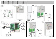
Kit <strong>di</strong> connessione <strong>per</strong> cavo scaldante autoregolante<br />
13<br />
Co<strong>di</strong>ce<br />
MVKITGR<br />
MVKITGR:<br />
MVBOX:<br />
1 cassetta <strong>di</strong> connessione<br />
3 set <strong>di</strong> connessione in cassetta<br />
1 kit <strong>di</strong> connessione lato terminale<br />
+ foglio <strong>di</strong> istruzioni <strong>per</strong> il montaggio<br />
1 set <strong>di</strong> connessione<br />
1 kit <strong>di</strong> connessione lato terminale<br />
+ foglio <strong>di</strong> istruzioni <strong>per</strong> il montaggio<br />
1 cassetta <strong>di</strong> connessione<br />
Termostato ambiente (MVTH)<br />
Specifiche tecniche :<br />
Custo<strong>di</strong>a antispruzzo, grado <strong>di</strong> protezione IP65, con interruttore <strong>di</strong> regolazione ad<br />
incasso. Differenziale t = 2°C a 16A.<br />
Il cavo scaldante autoregolante è collegato a un’uscita da 220V/230V e deve<br />
essere protetto con un fusibile da 16A e un magnetotermico non su<strong>per</strong>iore a 30µA.<br />
Attenzione : a una tem<strong>per</strong>atura <strong>di</strong> 0°C la lunghezza massima del circuito non<br />
deve su<strong>per</strong>are i 100 m.<br />
Nota: l’uso <strong>di</strong> un termostato è raccomandato.<br />
Il cavo scaldante autoregolante è sempre<br />
collegato a un’uscita da 220V/230V,<br />
in<strong>di</strong>pendentemente dalla sua lunghezza.<br />
Il grafico a lato mostra la curva termica.<br />
Date le sue proprietà autoregolanti, il<br />
cavo scaldante interviene in presenza <strong>di</strong><br />
variazioni <strong>di</strong> tem<strong>per</strong>atura lungo l’intero<br />
impianto.<br />
L’acqua stagnante può raggiungere una<br />
tem<strong>per</strong>atura <strong>di</strong> 35°C o più.<br />
Si raccomanda l’uso <strong>di</strong> un termostato <strong>per</strong><br />
comandare il <strong>di</strong>sinserimento del circuito,<br />
riducendo così il consumo <strong>di</strong> energia.<br />
W/m<br />
14,0<br />
12,0<br />
10,0<br />
8,0<br />
6,0<br />
4,0<br />
2,0<br />
0,0<br />
- 10 0 10 20 30 40 50 60 70 °C
TUBAZIONI PREISOLATE MICROFLEX<br />
Tubi preisolati antigelo<br />
con cavo scaldante autoregolante<br />
14<br />
Questa tabella mostra la <strong>di</strong>s<strong>per</strong>sione termica quando la guaina del tubo è esposta a una tem<strong>per</strong>atura ambiente<br />
negativa. Se la <strong>di</strong>s<strong>per</strong>sione termica è su<strong>per</strong>iore a 9 W/m sussiste il <strong>per</strong>icolo <strong>di</strong> gelo.<br />
Ø tubo 32 25 32 32 40 40 40 50 50 63 63 75 75 90 90<br />
guaina esterna 75 125 90* 125 90* 125* 160 125* 160 125* 160 160* 200 160* 200<br />
Spessore 19 41 22 37,5 18 33 50 28 46 22 40 34 52 26 44<br />
isolamento mm mm mm mm mm mm mm mm mm mm mm mm mm mm mm<br />
Tem<strong>per</strong>atura - 1 1 1 1 1 1 1 1 1 1 1 1 1 1 1 1<br />
tubo - 2 1 1 1 1 1 1 1 1 1 2 1 2 1 2 1<br />
esterno - 3 1 1 1 1 2 1 1 2 1 2 1 2 1 3 2<br />
- 4 2 1 2 1 2 2 1 2 1 3 2 2 2 3 2<br />
- 5 2 1 2 1 2 2 1 2 2 3 2 3 2 4 3<br />
- 6 2 1 2 2 3 2 2 3 2 3 2 3 2 4 3<br />
- 7 2 2 3 2 3 2 2 3 2 4 2 3 3 5 3<br />
- 8 3 2 3 2 4 3 2 3 2 4 3 4 3 5 4<br />
- 9 3 2 3 2 4 3 2 4 3 5 3 4 3 6 4<br />
-10 3 2 3 3 4 3 2 4 3 5 4 5 3 6 4<br />
- 11 4 2 4 3 5 3 3 4 3 6 4 5 4 7 5<br />
- 12 4 3 4 3 5 4 3 5 3 6 4 5 4 7 5<br />
- 13 4 3 4 3 5 4 3 5 4 7 4 6 4 8 5<br />
- 14 4 3 5 3 6 4 3 5 4 7 5 6 5 8 6<br />
- 15 5 3 5 4 6 4 3 6 4 7 5 6 5 9 6<br />
- 16 5 3 5 4 6 5 4 6 4 8 5 7 5 9 6<br />
- 17 5 3 6 4 7 5 4 6 5 8 6 7 5 10 7<br />
- 18 5 4 6 4 7 5 4 6 5 9 6 8 6 10 7<br />
- 19 6 4 6 4 8 5 4 7 5 9 6 8 6 10 7<br />
- 20 6 4 6 5 8 6 4 7 5 9 7 8 6 11 8<br />
- 21 6 4 7 5 8 6 5 7 6 10 7 9 7 11 8<br />
- 22 6 4 7 5 9 6 5 8 6 10 7 9 7 12 8<br />
- 23 7 4 7 5 9 6 5 8 6 11 7 9 7 12 9<br />
- 24 7 5 7 6 9 7 5 8 6 11 8 10 7 13 9<br />
- 25 7 5 8 6 10 7 5 9 6 12 8 10 8 13 9<br />
- 26 7 5 8 6 10 7 6 9 7 12 8 10 8 14 10<br />
- 27 8 5 8 6 10 7 6 9 7 12 8 11 8 14 10<br />
- 28 8 5 9 6 11 7 6 10 7 13 9 11 9 15 10<br />
- 29 8 5 9 7 11 8 6 10 7 13 9 12 9 15 11<br />
- 30 8 6 9 7 11 8 6 10 8 14 9 12 9 16 11<br />
- 31 9 6 9 7 12 8 6 10 8 14 10 12 9 16 11<br />
- 32 9 6 10 7 12 8 7 11 8 14 10 13 10 17 12<br />
- 33 9 6 10 7 12 9 7 11 8 15 10 13 10 17 12<br />
- 34 9 6 10 8 13 9 7 11 8 15 10 13 10 18 12<br />
- 35 10 6 10 8 13 9 7 12 9 16 11 14 10 18 13<br />
- 36 10 7 11 8 13 9 7 12 9 16 11 14 11 18 13<br />
- 37 10 7 11 8 14 10 8 12 9 16 11 14 11 19 13<br />
- 38 10 7 11 8 14 10 8 13 9 17 11 15 11 19 14<br />
- 39 11 7 12 8 14 10 8 13 10 17 12 15 11 20 14<br />
- 40 11 7 12 9 15 10 8 13 10 18 12 15 12 20 14<br />
- 41 11 7 12 9 15 10 8 13 10 18 12 16 12 21 15<br />
- 42 11 8 12 9 15 11 8 14 10 18 13 16 12 21 15<br />
- 43 12 8 13 9 16 11 9 14 10 19 13 16 12 22 15<br />
- 44 12 8 13 9 16 11 9 14 11 19 13 17 13 22 16<br />
- 45 12 8 13 10 16 11 9 15 11 19 13 17 13 23 16<br />
- 46 12 8 13 10 17 12 9 15 11 20 14 17 13 23 16<br />
- 47 13 8 14 10 17 12 9 15 11 20 14 18 13 23 16<br />
- 48 13 9 14 10 17 12 10 15 11 21 14 18 14 24 17<br />
- 49 13 9 14 10 17 12 10 16 12 21 14 18 14 24 17<br />
- 50 13 9 14 11 18 12 10 16 12 21 15 19 14 25 17
TUBAZIONI PREISOLATE MICROFLEX<br />
Cavi scaldanti autoregolanti: struttura e funzionamento<br />
15<br />
1 2 3 4<br />
5<br />
1. Conduttori in rame stagnato<br />
2. Matrice semiconduttiva autoregolante<br />
3. Guaina isolante<br />
4. Calza metallica <strong>di</strong> sicurezza in rame stagnato<br />
5. Rivestimento esterno <strong>di</strong> sicurezza<br />
Costruzione robusta<br />
Il cavo scaldante è un cavo autoregolante dotato <strong>di</strong> due conduttori paralleli multifilo in rame stagnato e <strong>di</strong> una matrice<br />
semiconduttiva interme<strong>di</strong>a.<br />
Questa matrice è isolata elettricamente tramite un rivestimento in poliolefina o in fluoropolimero. È rivestita da una<br />
calza metallica in rame stagnato che viene utilizzata come messa a terra (conduttore <strong>di</strong> sicurezza) del cavo<br />
scaldante, sod<strong>di</strong>sfa i principali standard <strong>di</strong> sicurezza e garantisce ulteriore protezione meccanica.<br />
Ciclo <strong>di</strong> vita garantito<br />
Nei nostri laboratori i cavi scaldanti autoregolanti sono oggetto <strong>di</strong> assidue prove, secondo quanto previsto dagli<br />
standard internazionali e in conformità ai meto<strong>di</strong> scientifici e alle procedure riconosciute. Queste prove hanno<br />
<strong>di</strong>mostrato che il ciclo <strong>di</strong> vita del cavo riscaldante autoregolante è <strong>di</strong> oltre 40 anni.<br />
Licenze<br />
Tutti i cavi scaldanti autoregolanti sono prodotti in conformità alle più severe norme <strong>di</strong> qualità e sono sottoposti a<br />
costanti controlli. Sono conformi a tutte le licenze CENELEC e a numerose altre licenze <strong>di</strong> fabbricazione, controllo,<br />
ecc. rilasciate in <strong>di</strong>versi paesi.<br />
Diagramma del circuito<br />
Circuiti paralleli<br />
Alimentando due conduttori paralleli in rame, la corrente attraversa la matrice semiconduttiva composta da molecole<br />
fini. Il <strong>di</strong>agramma del circuito elettrico è simile a un circuito parallelo in molte resistenze <strong>di</strong>pendenti dalla tem<strong>per</strong>atura.<br />
La costruzione lineare del sistema e le semplici o<strong>per</strong>azioni richieste <strong>per</strong> la sua installazione consentono una notevole<br />
ottimizzazione dei risparmi.<br />
Il cavo scaldante è sempre collegato a un’uscita da 220V, in<strong>di</strong>pendentemente dalla sua lunghezza.
TUBAZIONI PREISOLATE MICROFLEX<br />
Capacità termica<br />
16<br />
Tem<strong>per</strong>atura<br />
1 2 3<br />
1. Nelle sezioni fredde del cavo scaldante la struttura del<br />
materiale termoplastico si contrae generando numerose<br />
correnti elettriche che attraversano le particelle <strong>di</strong> carbone.<br />
Nella matrice semiconduttiva la corrente viene convertita in<br />
calore.<br />
2. Nelle sezioni tiepide la struttura del materiale termoplastico<br />
si <strong>di</strong>lata, interrompendo progressivamente il passaggio delle<br />
correnti nelle particelle <strong>di</strong> carbone. Di conseguenza aumenta<br />
il numero delle resistenze mentre si riduce la conduzione <strong>di</strong><br />
corrente e quin<strong>di</strong> l’erogazione <strong>di</strong> calore.<br />
3. Nelle sezioni calde la <strong>di</strong>latazione della struttura del<br />
materiale termoplastico interrompe quasi completamente il<br />
passaggio <strong>di</strong> corrente. Ne consegue una resistenza elettrica<br />
molto elevata e una caduta quasi a 0 della capacità termica.<br />
Funzionamento<br />
La matrice semiconduttiva si compone <strong>di</strong> un rivestimento in materiale termoplastico dalla speciale formulazione a<br />
molecole fini, miscelate con particelle <strong>di</strong> carbone in grado <strong>di</strong> generare correnti elettriche tra due conduttori paralleli<br />
in rame. All’aumento della tem<strong>per</strong>atura, il materiale termoplastico si espande <strong>per</strong> effetto della <strong>di</strong>latazione molecolare.<br />
Le particelle <strong>di</strong> carbone si separano sempre più, provocando l’interruzione delle correnti elettriche e l’aumento della<br />
resistenza elettrica nella matrice. La conduzione <strong>di</strong> corrente e il calore erogato precipitano <strong>di</strong> conseguenza.<br />
Quando la matrice si raffredda il processo si ripete al contrario e l’erogazione <strong>di</strong> calore aumenta in risposta alle basse<br />
tem<strong>per</strong>ature. La struttura molecolare fine della matrice le conferisce proprietà duroplastiche, rendendo <strong>per</strong>fettamente<br />
riproducibile a livello molecolare il comportamento <strong>di</strong> <strong>di</strong>latazione, anche in presenza <strong>di</strong> variazioni <strong>di</strong> tem<strong>per</strong>atura. Le<br />
proprietà autoregolanti del cavo scaldante sono insite nel materiale stesso e conferiscono al cavo scaldante la<br />
capacità <strong>di</strong> reagire alle variazioni <strong>di</strong> tem<strong>per</strong>atura in qualsiasi punto dell’impianto.<br />
Risparmio energetico<br />
Poiché la capacità scaldante si regola in base alle tem<strong>per</strong>ature locali, il consumo energetico è sempre proporzionale<br />
alle esigenze prevalenti. I cavi scaldanti <strong>per</strong>tanto consentono <strong>di</strong> ridurre i consumi energetici ed economici me<strong>di</strong>ante<br />
il principio dell’autoregolazione.<br />
Sicuro ed affidabile<br />
Date le sue proprietà autoregolanti, il sistema non è soggetto a surriscaldamento o deterioramento, anche in caso <strong>di</strong><br />
sovrapposizione del cavo scaldante.
TUBAZIONI PREISOLATE MICROFLEX<br />
Accessori<br />
I tappi antipolvere MS, MSD, MSQ servono unicamente allo scopo <strong>di</strong> prevenire l’ingresso della polvere.<br />
Tappi antipolvere <strong>per</strong> MICROFLEX ®<br />
UNO<br />
Co<strong>di</strong>ce Ø guaina Ø<br />
esterna<br />
tubo<br />
MS7525 75 25<br />
MS7532 75 32<br />
MS9032 90 32<br />
MS9040 90 40<br />
MS12540 125 40<br />
MS12550 125 50<br />
MS12563 125 63<br />
MS16040 160 40<br />
MS16050 160 50<br />
MS16063 160 63<br />
MS16075 160 75<br />
MS16090 160 90<br />
MS20075 200 75<br />
MS20090 200 90<br />
MS200110 200 110<br />
17<br />
Tappi antipolvere <strong>per</strong> MICROFLEX ®<br />
DUO<br />
Co<strong>di</strong>ce Ø guaina Ø<br />
esterna<br />
tubo<br />
MSD12525 125 2 x 25<br />
MSD12532 125 2 x 32<br />
MSD16025 160 2 x 25<br />
MSD16032 160 2 x 32<br />
MSD16040 160 2 x 40<br />
MSD16050 160 2 x 50<br />
MSD20050 200 2 x 50<br />
MSD20063 200 2 x 63<br />
MSD1252520 125 1 x 25 / 1 x 20<br />
MSD1253225 125 1 x 32 / 1 x 25<br />
MSD1603225 160 1 x 32 / 1 x 25<br />
MSD1604025 160 1 x 40 / 1 x 25<br />
MSD1605025 160 1 x 50 / 1 x 25<br />
MSD1605032 160 1 x 50 / 1 x 32<br />
Tappi antipolvere <strong>per</strong> MICROFLEX ®<br />
QUADRO<br />
Co<strong>di</strong>ce Ø guaina Ø<br />
esterna<br />
tubo<br />
MSQ160252520 160 2 x 25 / 1 x 25 / 1 x 20<br />
MSQ160322320 160 2 x 32 / 1 x 25 / 1 x 20<br />
MSQ160323225 160 2 x 32 / 1 x 32 / 1 x 25
TUBAZIONI PREISOLATE MICROFLEX<br />
I terminali termorestringenti MK prevengono l’ingresso <strong>di</strong> acqua tra la guaina e il tubo principale in PEX-a<br />
isolato (Istruzioni ve<strong>di</strong> pag.31).<br />
18<br />
Terminali termorestringenti <strong>per</strong> MICROFLEX ® UNO<br />
Co<strong>di</strong>ce Ø guaina Ø<br />
esterna<br />
tubo<br />
MK2000 75 25<br />
MK2100 75 / 90 32 o 40<br />
MK2200 125 40 o 50<br />
MK2400 125 63<br />
MK2340 160 40 o 50<br />
MK2500 160 da 63 a 90<br />
MK2600 200 da 75 a 110<br />
Terminali termorestringenti <strong>per</strong> MICROFLEX ® DUO<br />
Co<strong>di</strong>ce Ø guaina Ø<br />
esterna<br />
tubo<br />
MK3250-P604 125 1 x 25 / 1 x 20<br />
MK3250-P604 125 2 x 25<br />
MK3250-P604 125 1 x 32 / 1 x 25<br />
MK3280 125 2 x 32<br />
MK3350-01 160 2 x 25 o 2 x 32<br />
MK3350-02 160 2 x 40<br />
MK3350-01 160 1 x 32 / 1 x 25<br />
MK3350-02 160 1 x 40 / 1 x 25<br />
MK3360-01 160 1 x 50 / 1 x 25<br />
MK3350-03 160 2 x 50<br />
MK3350-03 200 2 x 50<br />
Manicotto modello LS <strong>per</strong> attraversamento muro (tenuta stagna)<br />
B<br />
A<br />
Questo manicotto è idoneo anche <strong>per</strong><br />
su<strong>per</strong>fici lisce (tubi <strong>di</strong> drenaggio, tubi in<br />
pressione..)<br />
* può essere usato in combinazione con il modello MCS<br />
1.<br />
2.<br />
3.<br />
1. Ricavare un foro in funzione delle<br />
<strong>di</strong>mensioni minime e massime (ve<strong>di</strong><br />
colonna 5).<br />
Applicare il manicotto LS sulla guaina<br />
esterna. Assicurarsi che a monte e a<br />
valle del manicotto vi sia un tratto<br />
rettilineo <strong>di</strong> almeno 60 cm.<br />
Non sono ammesse curvature.<br />
2. Inserire il tubo completo <strong>di</strong> manicotto<br />
nell’a<strong>per</strong>tura a muro.<br />
3. Serrando i bulloni in corrispondenza degli<br />
sno<strong>di</strong> equamente <strong>di</strong>stanziati, le piastrine<br />
<strong>di</strong> fissaggio risultano uniformemente<br />
compresse e riempiono lo spazio anulare<br />
tra il tubo e l’a<strong>per</strong>tura a muro.<br />
Co<strong>di</strong>ce Ø esterno Larghezza Micro-Sigillo A<strong>per</strong>tura nel Coppia<br />
Gommino Bulloni inclusi muro Nm<br />
in mm A B in mm Min. Max.<br />
9LS200 * 75 43 60 100 - 102 3,0 3,5<br />
7LS300 75 62 83 110 - 115 9,0 11,0<br />
8LS300 * 90 62 83 128 - 132 9,0 11,0<br />
9LS315 90 62 85 134 - 136 10,0 12,0<br />
7LS475 * 125 - - <strong>per</strong> MCS 8 26,0 32,5<br />
6LS325 125 65 115 175 - 180 11,8 14,5<br />
7LS325 * 160 65 115 209 - 212 11,8 14,5<br />
7LS400 160 86 145 240 - 245 30,0 37,0<br />
13LS300 160 62 83 200 - 202 9,0 11,0<br />
9LS325 200 65 115 250 - 255 11,8 14,5<br />
8LS400 200 86 145 275 - 282 30,0 37,0<br />
10LS575 * 200 - - <strong>per</strong> MCS 12 47,0 61,0
TUBAZIONI PREISOLATE MICROFLEX<br />
Manicotto <strong>per</strong> attraversamento muro MCS (Istruzioni a pag. 19).<br />
E<br />
430<br />
ØD1<br />
ØD2<br />
Co<strong>di</strong>ce Ø guaina Anello <strong>di</strong> tenuta D1 D2 E<br />
tubo<br />
MCS 4 75 9LS200 102 212 4,8<br />
MCS 5 90 8LS300 130 241 4,8<br />
MCS 8 125 7LS475 209 321 4,8<br />
MCS 8 160 7LS325 209 321 4,8<br />
MCS 12 200 10LS575 311 422 4,8<br />
Nota :<br />
L’art. MCS8 è utilizzabile sia <strong>per</strong> Ø 125 sia <strong>per</strong> Ø 160.<br />
A seconda del Ø occorre utilizzare i seguenti sigilli <strong>di</strong> contatto :<br />
Ø 125 = 7LS475; Ø 160 = 7LS325<br />
19<br />
Manicotto modello MMDV <strong>per</strong> montaggio a muro (non a tenuta stagna)<br />
2.<br />
Questo manicotto MICROFLEX <strong>per</strong> montaggio a muro si compone<br />
<strong>di</strong> un tubo corrugato in polietilene ad alta densità e <strong>di</strong> un manicotto<br />
termorestringente. Con il tubo corrugato incassato e sporgente dal<br />
muro <strong>di</strong> circa 100 mm, inserire il tubo Microflex e sigillarlo con il<br />
manicotto termorestringente.<br />
Lo spessore del muro deve essere inferiore a 400 mm.<br />
(Istruzioni a pag. 38).<br />
Manicotto <strong>per</strong> attraversamento muro<br />
(da incasso)<br />
ESTERNO<br />
Manicotto<br />
termorestringente<br />
Tappo<br />
INTERNO<br />
1.<br />
Manicotto <strong>per</strong><br />
attraversamento muro<br />
Co<strong>di</strong>ce Ø guaina Ø manicotto Ø a<strong>per</strong>tura<br />
dettaglio 1 dettaglio 2 muro<br />
mm mm mm<br />
MMDV75 75 110 210<br />
MMDV90 90 110 210<br />
MMDV125 125 160 260<br />
MMDV160 160 200 300<br />
MMDV200 200 250 350<br />
Manicotti MCS <strong>per</strong> attraversamento muro in strutture a getto <strong>di</strong> cemento<br />
Coprigiunto e<br />
nervatura<br />
Tubo<br />
Microflex<br />
Micro - Seal<br />
Descrizione<br />
Per la posa in o<strong>per</strong>a <strong>di</strong> tubi che attraversano murature e<br />
solai in strutture <strong>di</strong> nuova costruzione, possono essere<br />
impiegati manicotti CS non metallici, prodotti <strong>per</strong><br />
stampaggio in polietilene ad alta densità. Leggeri e<br />
facilmente manovrabili, sono ideali <strong>per</strong> le strutture<br />
realizzate a getto <strong>di</strong> cemento.<br />
Muro<br />
Micro - Seal<br />
Provvisti <strong>di</strong> coprigiunto e nervature <strong>di</strong> rinforzo<br />
incorporate, questi manicotti rimangono ancorati al muro,<br />
contrastando le forze originate dalla gittata.<br />
Sono previsti tappi terminali <strong>per</strong> semplificarne e renderne<br />
più accurato il posizionamento all’interno delle<br />
casseforme. Nell’eventualità <strong>di</strong> mo<strong>di</strong>fiche in cantiere, è<br />
possibile accorciarli servendosi <strong>di</strong> semplici utensili<br />
manuali.<br />
Normale<br />
Compresso<br />
Il manicotto è appositamente realizzato con su<strong>per</strong>ficie<br />
esterna zigrinata <strong>per</strong> garantire una maggiore adesione<br />
alle interfacce <strong>di</strong> cemento rispetto alla maggior parte dei<br />
prodotti in materiale plastico.
TUBAZIONI PREISOLATE MICROFLEX<br />
Installazione<br />
20<br />
430 mm<br />
D1<br />
D2<br />
1. L’installazione <strong>di</strong> tappi terminali su<br />
entrambe le estremità del manicotto<br />
serve a prevenirne la deformazione<br />
durante le fasi iniziali della gittata <strong>di</strong><br />
cemento e a mantenere il manicotto<br />
esattamente in posizione.<br />
2. Corpo del manicotto inserito sul<br />
tappo terminale.<br />
3. Inserimento dell’altro tappo terminale<br />
nel manicotto.<br />
L’ampia area flangiata del tappo<br />
assicura un’ottima su<strong>per</strong>ficie <strong>di</strong><br />
appoggio alla cassaforma e resiste<br />
al peso della gittata <strong>di</strong> cemento.<br />
4. L’o<strong>per</strong>atore verifica la corretta<br />
installazione del manicotto prima <strong>di</strong><br />
innalzare la parete all’esterno della<br />
cassaforma.<br />
5. Anche in seguito al <strong>di</strong>sarmo, il<br />
tappo terminale resta in posizione<br />
poiché serve a proteggere il<br />
manicotto dalla sporcizia e dalle<br />
incrostazioni.<br />
6. Prima dell’inserimento del tubo, i<br />
tappi vengono rimossi <strong>per</strong> rivelare<br />
una su<strong>per</strong>ficie interna del manicotto<br />
priva <strong>di</strong> contaminazioni.<br />
Manicotto termorestringente MHM <strong>per</strong> riparazioni<br />
Guaina<br />
Manicotto<br />
termorestringente<br />
Per la riparazione delle guaine esterne in caso <strong>di</strong> danno accidentale:<br />
1. far scorrere il manicotto termorestringente sulla guaina fino a coprire la<br />
parte danneggiata.<br />
2. servendosi <strong>di</strong> una pistola termocollante, far aderire il manicotto alla<br />
guaina (facendo attenzione a non bruciarla!)<br />
3. premere il manicotto, indossando guanti protettivi<br />
4. la guaina danneggiata è ora sigillata ermeticamente!<br />
(Per ulteriori dettagli vedere pagina 40).<br />
*Su richiesta è <strong>di</strong>sponibile anche il<br />
manicotto termorestringente con<br />
larghezza 450 mm<br />
Co<strong>di</strong>ce Ø Guaina Larghezza manicotto<br />
termorestringente<br />
MHM75 75 220 mm*<br />
MHM90 90 220 mm*<br />
MHM125 125 220 mm*<br />
MHM160 160 220 mm*<br />
MHM200 200 220 mm*
TUBAZIONI PREISOLATE MICROFLEX<br />
Co<strong>di</strong>ce Nastro <strong>di</strong> riparazione Lunghezza<br />
x larghezza<br />
MHB200 Nastro termorestringente 10 m x 200 m<br />
MHK150 Nastro <strong>di</strong> rivestimento applicabile a freddo 10 m x 150 m<br />
21<br />
(Istruzioni d’uso a pag. 39).<br />
Le custo<strong>di</strong>e isolanti Microflex in HDPE, realizzate a misura <strong>per</strong> i tubi Microflex, garantiscono<br />
massima sicurezza o<strong>per</strong>ativa.<br />
Custo<strong>di</strong>a isolante in PEX-a <strong>per</strong> manicotti<br />
Con i tubi principali già collegati ai raccor<strong>di</strong> terminali, l’installazione della custo<strong>di</strong>a offre ulteriore isolamento,<br />
sigillando la guaina esterna. Il set comprende lana <strong>di</strong> roccia, un kit <strong>di</strong> mastice <strong>di</strong> bitume pronto all’uso, bulloni in<br />
acciaio inox e un foglio <strong>di</strong> istruzioni.<br />
Co<strong>di</strong>ce Lunghezza Larghezza Altezza Peso Per guaina<br />
mm mm mm kg esterna<br />
MM129075 960 290 200 4,5 Ø 125/90/75<br />
MM201612 1170 345 270 5,5 Ø 200/160/125<br />
L<br />
Kit d’isolamento alternativo <strong>per</strong> manicotti<br />
Questo kit è proposto in alternativa ai kit MM129075 o MM201612. Si compone <strong>di</strong> una struttura tubulare che<br />
funge da manicotto, 2 manicotti termorestringenti, lana <strong>di</strong> roccia, nastro adesivo e un foglio <strong>di</strong> istruzioni.<br />
(Per ulteriori informazioni si veda a pag. 34).<br />
Taglio del materiale isolante<br />
Co<strong>di</strong>ce Lunghezza Per guaina<br />
mm<br />
esterna<br />
MM75 700 Ø 75<br />
MM90 700 Ø 90<br />
MM125 850 Ø 125<br />
MM160 1000 Ø 160<br />
MM200 1000 Ø 200<br />
Ø125 mm<br />
Ø160 mm<br />
Custo<strong>di</strong>a isolante <strong>per</strong> raccor<strong>di</strong> a T<br />
Una volta effettuato il collegamento dei tubi principali in PEX-a con i raccor<strong>di</strong> terminali, la custo<strong>di</strong>a offre ulteriore<br />
coibentazione, sigillando la guaina esterna. Il set comprende lana <strong>di</strong> roccia, un kit <strong>di</strong> mastice <strong>di</strong> bitume pronto<br />
all’uso, bulloni in acciaio inox e un foglio <strong>di</strong> istruzioni.<br />
(Per ulteriori informazioni si veda a pag. 32).<br />
Co<strong>di</strong>ce Lunghezza Larghezza Altezza Peso Per guaina<br />
mm mm mm kg esterna<br />
MT129075 960 590 200 5,5 Ø 125/90/75<br />
MT201612 1170 750 270 8,0 Ø 200/160/125<br />
L
TUBAZIONI PREISOLATE MICROFLEX<br />
22<br />
Custo<strong>di</strong>a isolante <strong>per</strong> raccor<strong>di</strong> a gomito<br />
Con i tubi principali in PEX-a già collegati ai raccor<strong>di</strong> terminali, l’installazione della custo<strong>di</strong>a offre ulteriore<br />
isolamento, sigillando la guaina esterna. Il set comprende lana <strong>di</strong> roccia, un kit <strong>di</strong> mastice <strong>di</strong> bitume pronto all’uso,<br />
bulloni in acciaio inox e un foglio <strong>di</strong> istruzioni.<br />
Co<strong>di</strong>ce Lunghezza Larghezza Altezza Peso Per mantello<br />
mm mm mm kg<br />
eMH201612 740 740 270 7,5 Ø 200/160/125<br />
L<br />
Custo<strong>di</strong>a isolante doppia <strong>per</strong> accoppiare 2 tubi singoli in 1 tubo doppio<br />
Con i tubi principali in PEX-a già collegati ai raccor<strong>di</strong> terminali, l’installazione della custo<strong>di</strong>a offre ulteriore<br />
isolamento, sigillando la guaina esterna. Il set comprende lana <strong>di</strong> roccia, un kit <strong>di</strong> mastice <strong>di</strong> bitume pronto all’uso,<br />
bulloni in acciaio inox e un foglio <strong>di</strong> istruzioni.<br />
Co<strong>di</strong>ce Lunghezza Larghezza Altezza Peso Per guaina<br />
mm mm mm kg esterna<br />
MBR201612 1170 460 230 7,0 Ø 200/160/125<br />
Pozzetto d’ispezione<br />
Questo pozzetto d’ispezione può essere impiegato in alternativa ai nostri kit isolanti MM, MT o MBR.<br />
Con i suoi 6 ingressi, è pre<strong>di</strong>sposto <strong>per</strong> il collegamento <strong>di</strong> numerosi tubi e valvole. Il set è completo <strong>di</strong> un kit <strong>di</strong><br />
mastice <strong>di</strong> bitume pronto all’uso, bulloni in acciaio inox e un foglio <strong>di</strong> istruzioni. Per ulteriori informazioni, si veda<br />
a pag. 35-37.<br />
810 mm<br />
Co<strong>di</strong>ce Diametro esterno Peso Per guaina<br />
della camera<br />
esterna<br />
mm<br />
kg<br />
MIS 810 35 6 x Ø 200/160/125<br />
Manicotto termorestringente <strong>per</strong> pozzetto d’ispezione<br />
MHM125 0,1 Ø 125<br />
MHM160 0,1 Ø 160<br />
MHM200 0,1 Ø 200<br />
Raccor<strong>di</strong> terminali Jentro ®<br />
Il raccordo terminale Jentro ® è un giunto <strong>di</strong> collegamento <strong>per</strong><br />
<strong>tubazioni</strong> in PEX <strong>di</strong> semplice installazione, anche in punti <strong>di</strong> <strong>di</strong>fficile<br />
accesso; non richiede utensili speciali ed è in grado <strong>di</strong> compensare<br />
senza problemi fenomeni <strong>di</strong> contrazione e <strong>di</strong>latazione del tubo.<br />
I raccor<strong>di</strong> Jentro ® sono raccor<strong>di</strong> professionali <strong>per</strong> impianti sanitari e<br />
<strong>di</strong> riscaldamento centralizzato.<br />
Sono <strong>di</strong>sponibili in versione <strong>di</strong>ritta con filetto maschio:<br />
- nelle misure da 25 a 110 mm <strong>per</strong> una pressione <strong>di</strong> 6 bar (0.6<br />
Mpa/84 Psi) <strong>per</strong> impianti <strong>di</strong> riscaldamento centralizato<br />
- nelle misure da 25 a 63 mm <strong>per</strong> una pressione <strong>di</strong> 10 bar (1 Mpa/140<br />
Psi) <strong>per</strong> impianti sanitari<br />
I raccor<strong>di</strong> terminali Jentro ® possono essere collegati con una vasta<br />
gamma <strong>di</strong> raccor<strong>di</strong> filettati, in modo da formare raccor<strong>di</strong> a T, a gomito<br />
o altri tipi <strong>di</strong> giunti ausiliari.
TUBAZIONI PREISOLATE MICROFLEX<br />
Istruzioni <strong>di</strong> montaggio<br />
23<br />
1. Utilizzando una paio <strong>di</strong><br />
forbici speciali o una pinza<br />
tagliatubi, tagliare il tubo in<br />
PEX-a ad angolo retto.<br />
2. Togliere le eventuali<br />
bavature con un utensile<br />
appropriato.<br />
3. Svitare il bullone e il<br />
dado in acciaio inox<br />
dall’anello <strong>di</strong> serraggio.<br />
4. Svitare il bullone e il<br />
dado in acciaio inox<br />
dall’anello <strong>di</strong> serraggio.<br />
5. Inserire una moneta o<br />
un oggetto simile nella<br />
fessura dell’anello <strong>di</strong><br />
serraggio.<br />
6. Inserire la vite corta<br />
nell’anello <strong>di</strong> serraggio e<br />
ruotarla in senso orario in<br />
<strong>di</strong>rezione della moneta.<br />
7. La moneta funge da<br />
battuta d’arresto <strong>per</strong> la vite<br />
e l’anello <strong>di</strong> serraggio si<br />
aprirà consentendone la<br />
facile rimozione.<br />
8. Spingere l’anello <strong>di</strong><br />
serraggio sul tubo, facendo<br />
attenzione a non ruotarlo.<br />
La tacca nell’anello <strong>di</strong><br />
serraggio deve essere<br />
rivolta verso il raccordo.<br />
9. Inserire il giunto nel tubo<br />
fino in fondo.<br />
10. Riposizionare l’anello<br />
<strong>di</strong> serraggio sul giunto.<br />
11. Allentare la vite e<br />
rimuovere la moneta.<br />
12. Riposizionare il bullone<br />
e il dado in acciaio inox e<br />
bloccare l’anello <strong>di</strong> serraggio<br />
utilizzando come guida le<br />
coppie in<strong>di</strong>cate <strong>di</strong> seguito.<br />
13. Tubo installato - Verificare sempre la tenuta come in<strong>di</strong>cato <strong>di</strong> seguito.<br />
- Svuotare l’intero impianto e applicare <strong>per</strong> 30 minuti<br />
una pressione d’esercizio moltiplicata <strong>per</strong> 1,5 rispetto<br />
alla normale pressione d’esercizio.<br />
Ø S M<br />
MS7525 75 25<br />
MS7532 75 32<br />
MS9032 90 32<br />
MS9040 90 40<br />
MS12540 125 40<br />
MS12550 125 50<br />
MS12563 125 63<br />
MS16040 160 40<br />
- Verificare la tenuta dei raccor<strong>di</strong>.<br />
- Ridurre rapidamente la pressione d’esercizio<br />
dell’intero impianto a un valore pari alla metà della<br />
normale pressione d’esercizio.<br />
- Al raggiungimento del valore desiderato, chiudere<br />
rapidamente la valvola <strong>di</strong> massima pressione.<br />
Se questo nuovo valore <strong>di</strong> pressione minima viene<br />
mantenuto <strong>per</strong> 90 minuti, i tubi e i raccor<strong>di</strong> sono a<br />
tenuta.<br />
- Effettuare quin<strong>di</strong> un controllo visivo dei raccor<strong>di</strong>.
TUBAZIONI PREISOLATE MICROFLEX<br />
24<br />
Raccor<strong>di</strong> Jentro ®<br />
<strong>per</strong> impianti <strong>di</strong> riscaldamento centralizzato<br />
Raccordo <strong>di</strong> collegamento <strong>di</strong>ritto, maschio<br />
Raccordo <strong>di</strong>ritto <strong>per</strong> collegamento PEX-a x PEX-a<br />
Raccordo a gomito <strong>per</strong> collegamento PEX-a x PEX-a<br />
6 bar<br />
6 bar<br />
Raccordo a Tee <strong>per</strong> collegamento n.3 PEX-a x PEX-a 6 bar<br />
Co<strong>di</strong>ce Ø filetto maschio Ø esterno tubo Ø Tubo/spessore muro<br />
pollici mm mm<br />
MJ13025/23 3 x 1" 25 - 25 - 25 25/2.3<br />
MJ13032/29 3 x 1" 32 - 32 - 32 32/2.9<br />
MJ1304032/37 2 x 1 1/4" + 1 x 1" 40 - 32 - 40 40/3.7 + 32/2.9<br />
MJ13040/37 3 x 1 1/4" 40 - 40 - 40 40/3.7<br />
MJ1305040/46 3 x 1 1/4" 50 - 40 - 50 50/4.6 + 40/3.7<br />
MJ13050/46 3 x 1 1/4" 50 - 50 - 50 50/4.6<br />
MJ1306350/57 2 x 2" + 1 x 1 1/4" 63 - 50 - 63 63/5.7 + 50/4.6<br />
MJ13063/57 3 x 2" 63 - 63 - 63 63/5.7<br />
MJ13075/69 3 x 2" 75 - 75 - 75 75/6.9<br />
MJ13090/82 3 x 3" 90 - 90 - 90 90/8.2<br />
MJ130110/10 3 x 3" 110 -110 -110 110/10<br />
Raccor<strong>di</strong> bicono<br />
6 bar<br />
Co<strong>di</strong>ce Ø filetto maschio Ø esterno tubo Ø Tubo/spessore muro<br />
pollici mm mm<br />
MJ3414425/23 1" 25 25/2.3<br />
MJ3414432/29 1" 32 32/2.9<br />
MJ3415440/37 1 1/4" 40 40/3.7<br />
MJ3415450/46 1 1/4" 50 50/4.6<br />
MJ341263/57 2" 63 63/5.7<br />
MJ341275/69 2" 75 75/6.9<br />
MJ341390/82 3" 90 90/8.2<br />
MJ3413110/10 3" 110 110/10<br />
Co<strong>di</strong>ce Ø filetto maschio Ø esterno tubo Ø Tubo/spessore muro<br />
pollici mm mm<br />
MJ27025/23 2 x 1" 25 x 25 25/2.3<br />
MJ27032/29 2 x 1" 32 x 32 32/2.9<br />
MJ27040/37 2 x 1 1/4" 40 x 40 40/3.7<br />
MJ27050/46 2 x 1 1/4" 50 x 50 50/4.6<br />
MJ27063/57 2 x 2" 63 x 63 63/5.7<br />
MJ27075/69 2 x 2" 75 x 75 75/6.9<br />
MJ27090/82 2 x 3" 90 x 90 90/8.2<br />
MJ270110/10 2 x 3" 110 x 110 110/10<br />
Co<strong>di</strong>ce Ø filetto maschio Ø esterno tubo Ø Tubo/spessore muro<br />
pollici mm mm<br />
MJ9025/23 2 x 1" 25 x 25 25/2.3<br />
MJ9032/29 2 x 1" 32 x 32 32/2.9<br />
MJ9040/37 2 x 1 1/4" 40 x 40 40/3.7<br />
MJ9050/46 2 x 1 1/4" 50 x 50 50/4.6<br />
MJ9063/57 2 x 2" 63 x 63 63/5.7<br />
MJ9075/69 2 x 2" 75 x 75 75/6.9<br />
MJ9090/82 2 x 3" 90 x 90 90/8.2<br />
MJ90110/10 2 x 3" 110 x 110 110/10<br />
Co<strong>di</strong>ce Ø Esterno tubo mm Attacco filettato Spessore DN<br />
VB3414425/23 25 x 3,5 1"<br />
VB3414432/29 32 x 2,9 1"<br />
VB3415440/37 40 x 3,7 1 1/4"<br />
VB3416450/46 50 x 4,6 1 1/2"<br />
Usare questi raccor<strong>di</strong> solo in installazioni accessibili
TUBAZIONI PREISOLATE MICROFLEX<br />
Raccor<strong>di</strong> Jentro ®<br />
<strong>per</strong> impianti sanitari<br />
Raccordo <strong>di</strong> collegamento <strong>di</strong>ritto, maschio<br />
10 bar<br />
Co<strong>di</strong>ce Ø filetto maschio Ø esterno tubo Ø spessore muro<br />
pollici mm mm<br />
MJ3414425/35 1" 25 25/3.5<br />
MJ3414432/44 1" 32 32/4.4<br />
MJ3415440/55 1 1/4" 40 40/5.5<br />
MJ3415450/69 1 1/4" 50 50/6.9<br />
MJ341263/87 2" 63 63/8.7<br />
25<br />
Raccordo <strong>di</strong>ritto <strong>per</strong> collegamento PEX-a x PEX-a<br />
10 bar<br />
Co<strong>di</strong>ce Ø filetto maschio Ø esterno tubo Ø spessore muro<br />
pollici mm mm<br />
MJ27025/35 2 x 1" 25 x 25 25/3.5<br />
MJ27032/44 2 x 1" 32 x 32 32/4.4<br />
MJ27040/55 2 x 1 1/4" 40 x 40 40/5.5<br />
MJ27050/69 2 x 1 1/4" 50 x 50 50/6.9<br />
MJ27063/87 2 x 2" 63 x 63 63/8.7<br />
Raccordo a gomito PEX x PEX<br />
10 bar<br />
Co<strong>di</strong>ce Ø filetto maschio Ø esterno tubo Ø spessore muro<br />
pollici mm mm<br />
MJ9025/35 2 x 1" 25 x 25 25/3.5<br />
MJ9032/44 2 x 1" 32 x 32 32/4.4<br />
MJ9040/55 2 x 1 1/4" 40 x 40 40/5.5<br />
MJ9050/69 2 x 1 1/4" 50 x 50 50/6.9<br />
MJ9063/87 2 x 2" 63 x 63 63/8.7<br />
Raccordo a Tee 3 PEX<br />
Raccor<strong>di</strong> bicono<br />
10 bar<br />
Co<strong>di</strong>ce Ø filetto maschio Ø esterno tubo Ø spessore muro<br />
pollici mm mm<br />
MJ13025/35 3 x 1" 25 - 25 - 25 25/3.5<br />
MJ13032/44 3 x 1" 32 - 32 - 32 32/4.4<br />
MJ1304032/55 2 x 1 1/4" + 1 x 1" 40 - 32 - 40 40/5.5 + 32/4,4<br />
MJ13040/55 3 x 1 1/4" 40 - 40 - 40 40/5.5<br />
MJ1305040/69 3 x 1 1/4" 50 - 40 - 50 50/6.9 + 40/5,5<br />
MJ13050/69 3 x 1 1/4" 50 - 50 - 50 50/6.9<br />
MJ1306350/87 2 x 2" + 1 x 1 1/4" 63 - 50 - 63 63/8.7 + 50/6,9<br />
MJ13063/87 3 x 2" 63 - 63 - 63 63/8.7<br />
Co<strong>di</strong>ce Ø Esterno tubo mm Attacco filettato Spessore DN<br />
VB3413420/28 20 x 2,8 3/4"<br />
VB3414425/35 25 x 3,5 1"<br />
VB3414432/44 32 x 4,4 1"<br />
VB3415440/55 40 x 5,5 1 1/4"<br />
VB3416450/69 50 x 6,9 1 1/2"<br />
VB341263/87 63 x 8,7 2"<br />
Usare questi raccor<strong>di</strong> dove sono accessibili
TUBAZIONI PREISOLATE MICROFLEX<br />
Manicotto F (ottone)<br />
26<br />
L<br />
Co<strong>di</strong>ce mm L mm DN<br />
VW27034 20 30 3/4"<br />
VW27044 25 35 1"<br />
VW27054 32 37 1 1/4"<br />
VW27064 40 42 1 1/2"<br />
VW2702 50 45 2"<br />
VW2703 80 55 3"<br />
Gomito 90°<br />
F x F (ottone)<br />
H<br />
Co<strong>di</strong>ce mm L mm H mm DN<br />
VW9034 20 x 20 49 30 3/4"<br />
VW9044 25 x 25 58 35 1"<br />
VW9054 32 x 32 68 42 1 1/4"<br />
VW9064 40 x 40 70 42 1 1/2"<br />
VW902 50 x 50 91 50 2"<br />
VW903 80 x 80 126 75 3"<br />
L<br />
Tee F (ottone)<br />
H<br />
Co<strong>di</strong>ce mm L mm H mm DN<br />
VW13034 3 x 20 60 30 3/4"<br />
VW13044 3 x 25 70 35 1"<br />
VW13054 3 x 32 84 42 1 1/4"<br />
VW13064 3 x 40 86 45 1 1/2"<br />
VW1302 3 x 50 105 55 2"<br />
VW1303 3 x 80 126 75 3"<br />
L<br />
Riduzione M/F (ottone) (Ottone o F = Raccor<strong>di</strong> <strong>di</strong> tubo <strong>di</strong> ferro malleabili)<br />
Co<strong>di</strong>ce mm L mm H mm DN<br />
VW2414434 25 x 20 16 1" x 3/4"<br />
VW2415434 32 x 20 20 1 1/4" x 3/4"<br />
VW2415444 32 x 25 20 1 1/4" x 1"<br />
VW2416444 40 x 25 21 1 1/2" x 1"<br />
VW2416454 40 x 32 21 1 1/2" x 1 1/4"<br />
VW241234 50 x 20 48 = F 2” x 3/4”<br />
VW241244 50 x 25 25 2" x 1"<br />
VW241254 50 x 32 25 2" x 1 1/4"<br />
VW241344 80 x 25 30 = F 3" x 1"<br />
VW241354 80 x 32 30 = F 3" x 1 1/4"<br />
VW24132 80 x 50 30 3" x 2"<br />
Attacco fisso<br />
Co<strong>di</strong>ce mm DN<br />
MFP25 25 1"<br />
MFP32 32 1 1/4"<br />
MFP50 50 2"
TUBAZIONI PREISOLATE MICROFLEX<br />
Flange<br />
Co<strong>di</strong>ce mm DN<br />
MDF44 25 1"<br />
MDF54 32 1 1/4"<br />
MDF2 50 2"<br />
MDF3 80 3"<br />
27<br />
Nastro <strong>di</strong> segnalazione<br />
ATTENZIONE:<br />
TUBO PER ACQUA<br />
ATTENZIONE: TUBO PER ACQUA<br />
CON CAVO SCALDANTE<br />
8 cm<br />
8 cm<br />
Co<strong>di</strong>ce<br />
MTRW<br />
MTRB<br />
Descrizione<br />
ATTENZIONE : TUBO PER ACQUA<br />
rotoli da 250 metri<br />
ATTENZIONE : TUBO PER ACQUA CON CAVO SCALDANTE<br />
rotoli da 250 metri<br />
ISTRUZIONI DI INSTALLAZIONE TUBAZIONI MICROFLEX<br />
Trasporto e immagazzinaggio<br />
Le <strong>tubazioni</strong> Microflex sono fornite in bobine <strong>di</strong> lunghezza massima pari a 100 metri. Le estremità dei tubi sono<br />
sigillate con tappi terminali protettivi <strong>per</strong> prevenire l’ingresso <strong>di</strong> contaminanti.<br />
In fase <strong>di</strong> immagazzinaggio occorre proteggere il tubo in PEX-a dalla luce solare e prevenire qualsiasi tipo <strong>di</strong><br />
deformazione della bobina.<br />
I tubi devono essere trasportati e immagazzinati in modo tale che oggetti contundenti, sassi o altri agenti esterni<br />
non possano danneggiarli. I tubi non devono essere trascinati <strong>per</strong> terra. Usare esclusivamente fascette <strong>di</strong> nylon<br />
o <strong>di</strong> tessuto <strong>per</strong> fissare le bobine durante il sollevamento o in fase <strong>di</strong> trasporto.<br />
Classificazione degli scavi<br />
Fino a una profon<strong>di</strong>tà <strong>di</strong> 120 cm si raccomanda <strong>di</strong> scavare una trincea verticale; <strong>per</strong> profon<strong>di</strong>tà su<strong>per</strong>iori a 120 cm<br />
è preferibile una trincea a V.<br />
I lavori <strong>di</strong> scavo devono essere eseguiti in modo conforme alle <strong>di</strong>sposizioni e alla regolamentazione delle autorità<br />
locali. Prima <strong>di</strong> procedere è spesso necessario ottenere un <strong>per</strong>messo.<br />
La profon<strong>di</strong>tà della trincea <strong>di</strong> servizio deve essere in accordo con le linee guida <strong>di</strong> pag. 28, relative alla posa dei<br />
tubi Microflex.<br />
La consultazione delle mappe catastali relative al territorio <strong>di</strong> attività potrebbe rivelarsi utile al fine <strong>di</strong> prevenire<br />
possibili conflitti con strutture e servizi esistenti o futuri.<br />
Al termine dei lavori <strong>di</strong> posa delle <strong>tubazioni</strong> è possibile segnalarne il <strong>per</strong>corso con un nastro segnalatore.<br />
Si raccomanda l’iscrizione al catasto.<br />
ATTENZIONE:<br />
Tem<strong>per</strong>atura <strong>di</strong> posa minima <strong>per</strong> i tubi Microflex: - 5°C.
TUBAZIONI PREISOLATE MICROFLEX<br />
Per la posa dei tubi sanitari tenere in debita considerazione la profon<strong>di</strong>tà <strong>di</strong> gelo del terreno.<br />
28<br />
Trincea <strong>per</strong> tubo doppio Microflex (DUO)<br />
;;;;;;;;;;<br />
;;;;;;;;;;<br />
;;;;;;;;;;<br />
;;;;;;;;;;<br />
;;;;;;;;;;<br />
;;;;;;;;;;<br />
;;;;;;;;;;<br />
;;;;;;;;;;<br />
;;;;;;;;;;<br />
;;;;;;;;;;<br />
;;;;;;;;;;<br />
;;;;<br />
;;;;<br />
;;;;<br />
R A A B C D b t* Scavo Riemp.<br />
Ø guaina larg. prof. m 3 /m m 3 /m<br />
mm mm mm mm mm mm mm circa circa<br />
125 150 100 150 250 425 625 0,27 0,17<br />
(650) (1025)<br />
160 180 100 150 250 520 660 0,34 0,22<br />
(650) (1060)<br />
200 180 100 150 250 560 700 0,39 0,25<br />
(650) (1100)<br />
1 Strato protettivo<br />
2 Nastro segnalatore del <strong>per</strong>corso<br />
3 Riempimento sabbioso<br />
4 Letto <strong>di</strong> posa sabbioso<br />
5 Tubo Microflex<br />
Trincea <strong>per</strong> 2 tubi Microflex singoli (2x UNO) senza collegamento sotterraneo<br />
;;;;;;;;;;<br />
;;;;;;;;;;<br />
;;;;;;;;;;<br />
;;;;;;;;;;<br />
;;;;;;;;;;<br />
;;;;;;;;;;<br />
;;;;;;;;;;<br />
;;;;;;;;;;<br />
;;;;;;;;;;<br />
;;;;;;;;;;<br />
;;;;;;;;;;<br />
;;;;<br />
;;;;<br />
;;;;<br />
R A A B C D b t* Scavo Riemp.<br />
Ø guaina larg. prof. m 3 /m m 3 /m<br />
mm mm mm mm mm mm mm circa circa<br />
75 150 100 150 250 550 575 0,32 0,20<br />
(650) (975)<br />
90 150 100 150 250 580 590 0,34 0,22<br />
(650) (990)<br />
125 150 100 150 250 650 625 0,41 0,26<br />
(650) (1025)<br />
200 180 100 150 250 860 700 0,60 0,38<br />
(650) (1100)<br />
1 Strato protettivo<br />
2 Nastro segnalatore del <strong>per</strong>corso<br />
3 Riempimento sabbioso<br />
4 Letto <strong>di</strong> posa sabbioso<br />
5 Tubo Microflex<br />
Trincea <strong>per</strong> 2 tubi Microflex singoli (2x UNO) con collegamento sotterraneo<br />
;;;;;;;;;;<br />
;;;;;;;;;;<br />
;;;;;;;;;;<br />
;;;;;;;;;;<br />
;;;;;;;;;;<br />
;;;;;;;;;;<br />
;;;;;;;;;;<br />
;;;;;;;;;;<br />
;;;;;;;;;;<br />
;;;;;;;;;;<br />
;;;;;;;;;;<br />
;;;;<br />
;;;;<br />
;;;;<br />
R A A B C D b t* Scavo Riemp.<br />
Ø guaina larg. prof. m 3 /m m 3 /m<br />
mm mm mm mm mm mm mm circa circa<br />
300 150 100 150 250 900 800 0,72 0,45<br />
(650) (1200)<br />
( ) I valori tra parentesi si riferiscono alla co<strong>per</strong>tura minima richiesta su un<br />
condotto interrato sotto un’area destinata ad intersezione stradale accessibile<br />
a carichi fino a 5.5 t/asse.
TUBAZIONI PREISOLATE MICROFLEX<br />
Prova <strong>di</strong> pressione<br />
Prova <strong>di</strong> pressione e risciacquo secondo DIN 1900 Parte 2<br />
29<br />
Quale prova degli interventi eseguiti a beneficio del cliente, la sezione 3.1.13 della nuova DIN 18581 relativa alle<br />
<strong>di</strong>sposizioni tecniche generali in materia <strong>di</strong> appalti <strong>per</strong> o<strong>per</strong>e e<strong>di</strong>li (ATV) prevede la compilazione e la consegna<br />
al cliente, tra i “documenti <strong>di</strong> accompagnamento rilevanti”, <strong>di</strong> un report relativo all’esecuzione della prova <strong>di</strong><br />
pressione.<br />
In questo report, che è soggetto ad approvazione da parte del cliente o <strong>di</strong> un suo rappresentante autorizzato,<br />
l’installatore dell’impianto verifica la conformità del suo lavoro con le regole della tecnica riconosciute e con gli<br />
obblighi contrattuali (quale prestazione secondaria da fornire secondo quanto sancito dalle norme VOB <strong>di</strong> gara e<br />
prestazioni negli appalti <strong>per</strong> o<strong>per</strong>e e<strong>di</strong>li, Parte B, § 4 e § 13).<br />
Le prove <strong>di</strong> pressione rappresentano un’attività <strong>di</strong> supporto concordata contrattualmente, essenziale ai fini<br />
dell’adempimento del contratto, facente anche parte delle prestazioni dell’appaltatore seppur non <strong>di</strong>chiarata nelle<br />
specifiche prestazioniali.<br />
La procedura della prova <strong>di</strong> pressione è obbligatoria<br />
Prima dell’occultamento del sistema <strong>di</strong> <strong>tubazioni</strong> Microflex, riempire le<br />
<strong>tubazioni</strong> finite <strong>di</strong> acqua, facendo attenzione ad evitare la formazione <strong>di</strong><br />
bolle d’aria. La prova <strong>di</strong> pressione si sud<strong>di</strong>vide in una prova preliminare<br />
seguita da una prova principale.<br />
Prova preliminare<br />
La prova preliminare prevede l’applicazione <strong>di</strong> una pressione <strong>di</strong> prova<br />
pari a 1,5 volte la pressione d’esercizio ammissibile. Tale pressione deve<br />
essere generata due volte nell’arco <strong>di</strong> 30 minuti a un intervallo <strong>di</strong> 10<br />
minuti. Dopo altri 30 minuti corrispondenti al <strong>per</strong>iodo <strong>di</strong> prova, la<br />
pressione <strong>di</strong> prova non dovrà essere caduta <strong>di</strong> oltre 0,6 bar (0,1 bar al<br />
minuto), in totale assenza <strong>di</strong> <strong>per</strong><strong>di</strong>te.<br />
Prova principale<br />
La prova principale, che deve essere condotta subito dopo la prova<br />
preliminare, dura 2 ore. Al termine <strong>di</strong> questo <strong>per</strong>iodo la pressione <strong>di</strong> prova<br />
registrata dopo la prova preliminare non dovrà essere caduta <strong>di</strong> oltre<br />
0,2 bar. Non devono verificarsi <strong>per</strong><strong>di</strong>te in alcun punto del sistema oggetto<br />
della prova.<br />
Note:<br />
Un ulteriore fattore che potrebbe con<strong>di</strong>zionare l’esito della prova è la<br />
<strong>di</strong>fferenza <strong>di</strong> tem<strong>per</strong>atura tra il tubo e il fluido <strong>di</strong> prova, causata dall’alto<br />
coefficiente <strong>di</strong> <strong>di</strong>latazione termica dei tubi in materiale plastico.<br />
Un’escursione termica <strong>di</strong> 10 K corrisponde approssimativamente a una<br />
variazione <strong>di</strong> pressione compresa tra 0,5 e 1 bar. Per questa ragione,<br />
occorre prendere tutte le precauzioni possibili <strong>per</strong> garantire che la<br />
tem<strong>per</strong>atura del fluido <strong>di</strong> prova rimanga costante durante l’esecuzione delle<br />
prove <strong>di</strong> pressione sui componenti del sistema costituiti da <strong>tubazioni</strong> in<br />
materiale plastico. In questo contesto è importante eseguire un’ispezione<br />
visiva <strong>di</strong> tutti i giunti durante l’esecuzione della prova <strong>di</strong> pressione, poiché<br />
l’es<strong>per</strong>ienza <strong>di</strong>mostra che non sempre è possibile rilevare le piccole <strong>per</strong><strong>di</strong>te<br />
semplicemente controllando il manometro. Al termine della prova <strong>di</strong><br />
pressione, le <strong>tubazioni</strong> <strong>di</strong> acqua potabile devono essere completamente<br />
lavate.<br />
Lavaggio del sistema <strong>di</strong> <strong>tubazioni</strong><br />
Per ragioni <strong>di</strong> protezione anticorrosione, l’elaborata procedura <strong>di</strong> risciacquo del sistema con una miscela <strong>di</strong><br />
aria/acqua come descritta in DIN 1988 Parte 2 non deve essere eseguita.<br />
Per la rimozione delle impurità grossolane, eseguire semplicemente il lavaggio del sistema <strong>di</strong> <strong>tubazioni</strong> con<br />
acqua.
TUBAZIONI PREISOLATE MICROFLEX<br />
Prova <strong>di</strong> tenuta - DIN 1988<br />
30<br />
2 Prova preliminare bar<br />
2.1 Pressione d’esercizio x 1,5<br />
2.2 Dopo 10 min. (ripetere 2.1)<br />
2.3 Dopo 20 min. (ripetere 2.1)<br />
2.4 Dopo 30 min.<br />
2.5 Dopo 60 min. caduta <strong>di</strong><br />
pressione ammissibile<br />
TUBAZIONI PREISOLATE MICROFLEX<br />
Nastro <strong>di</strong> segnalazione<br />
ATTENZIONE:<br />
TUBO PER ACQUA<br />
ATTENZIONE: TUBO PER ACQUA<br />
CON CAVO SCALDANTE<br />
8 cm<br />
8 cm<br />
Co<strong>di</strong>ce<br />
MTRW<br />
MTRB<br />
Descrizione<br />
ATTENZIONE : TUBO PER ACQUA<br />
rotoli da 250 metri<br />
ATTENZIONE : TUBO PER ACQUA CON CAVO SCALDANTE<br />
rotoli da 250 metri<br />
31<br />
Istruzioni <strong>di</strong> installazione a muro o soffitto<br />
A questo scopo, in ragione della sua <strong>flessibili</strong>tà, il tubo deve essere<br />
supportato ogni metro <strong>per</strong> tutta la sua lunghezza. Per evitare<br />
curvature il tubo deve essere legato con fascette a una struttura <strong>di</strong><br />
supporto.<br />
100 cm<br />
Montaggio a muro<br />
Linee guida <strong>per</strong> la posa aerea dei tubi<br />
Se la tubazione è destinata a posa aerea occorre prevedere punti <strong>di</strong> supporto <strong>per</strong> prevenirne lo spostamento. Su<br />
terreni accidentati, il tubo deve essere assicurato a intervalli <strong>di</strong> circa 25 m, facendo attenzione a garantirne un<br />
adeguato supporto. A questo scopo è possibile innalzare una struttura <strong>di</strong> supporto (ve<strong>di</strong> Istruzioni <strong>di</strong> installazione<br />
a muro o soffitto pag.31).<br />
I tubi Microflex devono essere protetti dall’esposizione <strong>di</strong>retta ai raggi UV.<br />
Linee guida <strong>per</strong> l’uso dei manicotti MK termorestringenti<br />
Far scorrere il manicotto sopra il tubo principale in PEX-a e la<br />
guaina.<br />
Servendosi <strong>di</strong> una pistola termoincollante o <strong>di</strong> una minitorcia<br />
con fiamma gialla (NON usare la fiamma azzurra!) far aderire<br />
delicatamente il manicotto.<br />
Comprimere il manicotto, indossando guanti protettivi.<br />
L’estremità finale del tubo è ora sigillata ermeticamente.
TUBAZIONI PREISOLATE MICROFLEX<br />
Linee guida <strong>per</strong> l’uso delle custo<strong>di</strong>e isolanti <strong>per</strong> raccor<strong>di</strong> a T<br />
32<br />
Quando un tubo doppio Microflex viene collegato in una<br />
custo<strong>di</strong>a isolata, si raccomanda <strong>di</strong> preferire una<br />
configurazione sovrapposta dei tubi, anziché<br />
giustapposta.<br />
Questo metodo serve a rendere ancora più semplice il<br />
montaggio dei raccor<strong>di</strong> terminali.<br />
In entrambe le parti della custo<strong>di</strong>a, simili a gusci (la<br />
parte su<strong>per</strong>iore è identica a quella inferiore), sono<br />
pre<strong>di</strong>sposti fori grezzi.<br />
Le custo<strong>di</strong>e sono progettate <strong>per</strong> alloggiare guaine dal<br />
<strong>di</strong>ametro pari a 125, 160 o 200 mm oppure a 75, 90 o<br />
125 mm e possono essere tagliate lungo una linea a<br />
scelta <strong>per</strong> ottenere il <strong>di</strong>ametro desiderato.<br />
Scorticare una lunghezza sufficiente <strong>di</strong> isolante e guaina<br />
dal tubo in PEX-a (facendo attenzione a non<br />
danneggiare il tubo) in modo da poter posizionare al<br />
centro dei tubi il raccordo terminale.<br />
Assicurarsi che il tubo Microflex preisolato su<strong>per</strong>i <strong>di</strong> 10<br />
cm il segno 200.<br />
Uno dei due gusci può essere utilizzato come <strong>di</strong>ma <strong>per</strong> definire la <strong>di</strong>stanza desiderata tra i tubi principali in PEX-a.<br />
Si raccomanda l’uso dei<br />
manicotti MK<br />
termorestringenti<br />
(ve<strong>di</strong> pagg. 18 e 31).<br />
Tagliare le strisce <strong>di</strong> bitume (2 <strong>per</strong> manicotto o raccordo<br />
a gomito e 3 <strong>per</strong> raccordo a T) adattandole al <strong>di</strong>ametro<br />
esterno della custo<strong>di</strong>a del tubo.<br />
Rimuovere lo strato protettivo e far aderire le strisce <strong>di</strong><br />
bitume all’interno delle custo<strong>di</strong>e isolanti in<br />
corrispondenza dei punti <strong>di</strong> ingresso (2 o 3) del tubo.<br />
Ø125 mm<br />
Ø160 mm<br />
pretagliare il<br />
materiale isolante<br />
Avvolgere il rivestimento isolante, tagliato su misura,<br />
intorno al tubo <strong>di</strong> servizio in modo da coprire<br />
adeguatamente i giunti.<br />
Legare con il nastro fornito in dotazione.
TUBAZIONI PREISOLATE MICROFLEX<br />
Ø125 mm<br />
Applicare il kit <strong>di</strong> mastice <strong>di</strong> bitume sulle scanalature <strong>di</strong><br />
entrambi i gusci della custo<strong>di</strong>a a intervalli regolari, fino a<br />
raggiungere uno spessore <strong>di</strong> 4 mm (<strong>per</strong> una larghezza<br />
<strong>di</strong> 5 mm).<br />
33<br />
Ø160 mm<br />
Ø200 mm<br />
Una volta collegati, posizionare i tubi in uno dei gusci<br />
della custo<strong>di</strong>a.<br />
Applicare il kit <strong>di</strong> mastice <strong>di</strong> bitume a intervalli regolari<br />
lungo le flange del guscio su<strong>per</strong>iore e inferiore della<br />
custo<strong>di</strong>a (a fianco dei fori), ottenendo uno spessore <strong>di</strong><br />
circa 6 mm.<br />
dettaglio<br />
Fare attenzione ad allineare i due gusci della custo<strong>di</strong>a.<br />
Serrare i bulloni in acciaio inox.<br />
Accertarsi che il kit <strong>di</strong> mastice <strong>di</strong> bitume venga<br />
espulso attraverso le a<strong>per</strong>ture laterali.
TUBAZIONI PREISOLATE MICROFLEX<br />
Linee guida <strong>per</strong> l’uso dei set <strong>di</strong> manicotti isolanti MM75-MM200<br />
34<br />
Il set si compone <strong>di</strong> 1 manicotto rigido e<br />
2 manicotti termorestringenti.<br />
Far scorrere il manicotto rigido sul tubo<br />
Microflex.<br />
in alternativa<br />
Si raccomanda l’uso dei manicotti MK<br />
termorestringenti (ve<strong>di</strong> pagg. 18 e 31)<br />
Fissare i raccor<strong>di</strong> terminali.<br />
Avvolgere il rivestimento isolante sul<br />
tubo <strong>di</strong> servizio, avendo cura <strong>di</strong> coprire<br />
adeguatamente i giunti. Legare con il<br />
nastro fornito in dotazione.<br />
Far scorrere all’in<strong>di</strong>etro il manicotto<br />
rigido in modo da alloggiarvi i giunti.<br />
Servendosi <strong>di</strong> una pistola<br />
termoincollante o <strong>di</strong> una minitorcia con<br />
fiamma gialla (NON usare la fiamma<br />
azzurra!) far aderire delicatamente<br />
entrambi i manicotti <strong>per</strong> metà sul<br />
manicotto rigido e <strong>per</strong> metà sulla<br />
guaina del tubo Microflex.<br />
Co<strong>di</strong>ce L1 L2 L3<br />
MM75/90 60 220 700<br />
MM125 80 260 850<br />
MM160 100 350 1000<br />
MM200 120 400 1000
TUBAZIONI PREISOLATE MICROFLEX<br />
Pozzetto d’ispezione<br />
Questo pozzetto d’ispezione può essere utilizzato in alternativa ai nostri kit MM, MT o MBR. Provvisto <strong>di</strong> 6 ingressi<br />
a sezioni marcate, ciascuno dei quali può essere tagliato su misura in funzione <strong>di</strong> <strong>di</strong>versi <strong>di</strong>ametri d’a<strong>per</strong>tura (125,<br />
160 o 160 mm), consente <strong>di</strong> realizzare vari collegamenti, compreso l’alloggiamento <strong>di</strong> valvole d’intercettazione.<br />
L’unità è fornita completa <strong>di</strong> co<strong>per</strong>chio su<strong>per</strong>iore, bulloni in acciaio inox, kit <strong>di</strong> mastice <strong>di</strong> bitume e un foglio <strong>di</strong><br />
istruzioni.<br />
Seguendo i passi illustrati <strong>di</strong> seguito, il collegamento risulterà im<strong>per</strong>meabile all’acqua.<br />
35<br />
Preparazione<br />
Attenzione!<br />
Una volta terminati gli scavi delle trincee, compattare con cura il primo strato protettivo utilizzando una pala<br />
escavatrice. Quando lo strato protettivo raggiunge uno spessore <strong>di</strong> circa 50 cm sopra la generatrice su<strong>per</strong>iore del<br />
tubo, è possibile utilizzare un rullo <strong>per</strong> compattare il terreno sottostante.<br />
Apporre un nastro segnalatore! Co<strong>di</strong>ce MTRW.<br />
Installazione<br />
Gli ingressi sono a sezioni marcate <strong>per</strong> facilitarne il taglio in funzione del <strong>di</strong>ametro d’a<strong>per</strong>tura desiderato.<br />
Appoggiare delicatamente il pozzetto d’ispezione su un letto <strong>di</strong> posa, liberato da oggetti appuntiti.<br />
Giunzione<br />
Prima <strong>di</strong> collegare i tubi nel pozzetto d’ispezione, procedere come segue :<br />
1. far scorrere un tappo termorestringente (modello MK) sopra la guaina e il tubo <strong>di</strong> servizio. Servendosi <strong>di</strong> una<br />
pistola termocollante o <strong>di</strong> una minitorcia con fiamma gialla (NON usare la fiamma azzurra!) far aderire<br />
delicatamente il manicotto.<br />
Dettaglio<br />
Co<strong>di</strong>ce MK<br />
Tappo<br />
termorestringente<br />
2. far scorrere un manicotto termorestringente (modello MHM) sopra la guaina, prima <strong>di</strong> inserire il tubo Microflex<br />
nel pozzetto d’ispezione.
TUBAZIONI PREISOLATE MICROFLEX<br />
36<br />
Ve<strong>di</strong> dettaglio<br />
Manicotto termorestringente<br />
Realizzare nel pozzetto tutte le giunzioni necessarie. Far aderire delicatamente il manicotto MHM sopra la guaina,<br />
servendosi <strong>di</strong> una pistola termoincollante o <strong>di</strong> una minitorcia <strong>per</strong> assicurare un collegamento im<strong>per</strong>mebile tra la<br />
guaina e il pozzetto d’ispezione.<br />
Possibilità <strong>di</strong> <strong>di</strong>ramazione<br />
Il pozzetto d’ispezione, realizzato in polietilene resistente agli urti, è molto solido e offre la possibilità <strong>di</strong> eseguire:<br />
- <strong>di</strong>ramazioni da tubi Microflex UNO a DUO (ve<strong>di</strong> schema 1)<br />
- <strong>di</strong>ramazioni da Microflex DUO a DUO (sia in impianti <strong>di</strong> riscaldamento centralizzato sia in impianti sanitari) (ve<strong>di</strong><br />
schema 2)<br />
- <strong>di</strong>ramazioni <strong>di</strong> più tubi Microflex DUO dal <strong>di</strong>ametro <strong>di</strong>verso (ve<strong>di</strong> schema 3)<br />
Schema 1 Schema 2 Schema 3<br />
Serrare i bulloni
TUBAZIONI PREISOLATE MICROFLEX<br />
Sigillatura del pozzetto d’ispezione<br />
Applicare uniformemente il kit <strong>di</strong> mastice <strong>di</strong> bitume sul bordo del corpo<br />
del pozzetto fino a raggiungere uno spessore <strong>di</strong> circa 10 mm (<strong>per</strong> una<br />
larghezza <strong>di</strong> 10 mm).<br />
37<br />
Posizionare il co<strong>per</strong>chio convesso sul corpo. Serrare i 6 bulloni in<br />
acciaio inox.<br />
Ruotare delicatamente il co<strong>per</strong>chio in senso orario, facendo attenzione<br />
a non danneggiare la guarnizione posta tra il corpo e l’elemento <strong>di</strong><br />
chiusura. Non imprimere una forza eccessiva.<br />
Rivestimento<br />
Letto <strong>di</strong> posa<br />
compattato<br />
Letto <strong>di</strong> posa<br />
compattato<br />
Letto <strong>di</strong> posa<br />
compattato<br />
Dimensioni d’ingombro
TUBAZIONI PREISOLATE MICROFLEX<br />
Linee guida <strong>per</strong> l’uso del manicotto MMDV <strong>di</strong> attraversamento muro<br />
(non a tenuta stagna)<br />
38<br />
Questo manicotto <strong>di</strong> attraversamento muro si compone<br />
<strong>di</strong> una guaina corrugata e <strong>di</strong> un manicotto<br />
termorestringente.<br />
Incassare la guaina corrugata prevedendo una<br />
sporgenza dal muro <strong>di</strong> circa 100 mm.<br />
Far scorrere il manicotto sopra il tubo Microflex. NON<br />
TAGLIARE MAI IL MANICOTTO NEL SENSO<br />
DELLA LUNGHEZZA!<br />
Premere il tubo Microflex attraverso la guaina<br />
corrugata precedentemente incassata.<br />
Servendosi <strong>di</strong> una pistola termocollante o <strong>di</strong> una<br />
minitorcia con fiamma gialla (NON usare la fiamma<br />
azzurra!) far aderire delicatamente il manicotto <strong>per</strong><br />
metà sul tubo corrugato e <strong>per</strong> metà sulla guaina del<br />
tubo Microflex.<br />
Su<strong>per</strong>ficie calda<br />
Premere il manicotto, utilizzando guanti protettivi.<br />
Ora il manicotto <strong>di</strong> attraversamento muro è pronto.<br />
Finitura<br />
Lo spazio anulare tra il tubo Microflex e l’a<strong>per</strong>tura a muro<br />
deve essere riempito con cura.<br />
Dimensioni<br />
Tubo Microflex 75 90 125 160 200<br />
Tubo corrugato 110 110 160 200 250<br />
A<strong>per</strong>tura a muro 210 210 260 300 350
TUBAZIONI PREISOLATE MICROFLEX<br />
Linee guida <strong>per</strong> l’uso dei nastri <strong>di</strong> rivestimento termorestringente<br />
MHB200 e a freddo MHK150<br />
MHB200 e MHK150<br />
39<br />
Assicurarsi che la guaina del tubo sia asciutta e<br />
pulita.<br />
Far scorrere il manicotto termorestringente sopra il<br />
tubo Microflex danneggiato.<br />
NON TAGLIARE MAI IL MANICOTTO NEL<br />
SENSO DELLA LUNGHEZZA!<br />
MHB200<br />
MHK150<br />
Servendosi <strong>di</strong> una pistola termoincollante o <strong>di</strong> una<br />
minitorcia con fiamma gialla (NON usare la fiamma<br />
azzurra!), far aderire delicatamente il manicotto <strong>per</strong><br />
riparazioni.<br />
Su<strong>per</strong>ficie calda<br />
Premere il manicotto, indossando guanti protettivi.<br />
Premere con decisione intorno alla guaina del tubo.<br />
MHB200 e MHK150<br />
La guaina danneggiata è ora sigillata ermeticamente.<br />
Per guaina esterna<br />
con <strong>di</strong>ametro pari a<br />
75mm<br />
90mm<br />
125mm<br />
160mm<br />
200mm<br />
Utilizzare la lunghezza<br />
305mm<br />
355mm<br />
465mm<br />
575mm<br />
700mm
TUBAZIONI PREISOLATE MICROFLEX<br />
Linee guida <strong>per</strong> l’uso del manicotto termorestringente MHM<br />
40<br />
Assicurarsi che la guaina del tubo sia asciutta e pulita.<br />
Avvolgere il manicotto <strong>per</strong> riparazioni intorno alla<br />
guaina danneggiata, avendo cura <strong>di</strong> sovrapporre gli<br />
strati <strong>di</strong> circa 7 cm)<br />
Servendosi <strong>di</strong> una pistola termoincollante o <strong>di</strong> una<br />
minitorcia con fiamma gialla (NON usare la fiamma<br />
azzurra!), far aderire delicatamente il manicotto <strong>per</strong><br />
riparazioni.<br />
Su<strong>per</strong>ficie calda<br />
Premere il manicotto, indossando guanti protettivi.<br />
La guaina danneggiata è ora sigillata ermeticamente.<br />
Per guaina esterna<br />
con <strong>di</strong>ametro pari a<br />
75mm<br />
90mm<br />
125mm<br />
160mm<br />
200mm<br />
Utilizzare la lunghezza<br />
305mm<br />
355mm<br />
465mm<br />
575mm<br />
700mm
TUBAZIONI PREISOLATE MICROFLEX<br />
Fissaggio del tubo<br />
In trincea:<br />
Assicurarsi scrupolosamente che il tracciato del tubo abbia un<br />
andamento a serpentina.<br />
Per fissare i cavi nella posizione desiderata, introdurre la sabbia <strong>di</strong><br />
riempimento protettivo a strati regolari.<br />
Nei fabbricati:<br />
Installare bracciali a punto fisso, preferibilmente all’ingresso del<br />
fabbricato. I bracciali, fissati sui tubi <strong>di</strong> trasporto del fluido, ne<br />
compensano la contrazione o l’espasione.<br />
Un fenomeno piuttosto comune che potrebbe verificarsi in fase <strong>di</strong><br />
installazione è un lieve arretramento dell’isolante.<br />
41<br />
In presenza <strong>di</strong> variazioni <strong>di</strong> tem<strong>per</strong>atura i tubi in Pex-a sono soggetti a forze <strong>di</strong> contrazione e <strong>di</strong>latazione, illustrate<br />
nelle tabelle seguenti in funzione dei vari <strong>di</strong>ametri.<br />
T 10ºK 20ºK 30ºK 40ºK 50ºK 60ºK 70ºK 80ºK 90ºK 100ºK<br />
Afm. (mm) F [N] F [N] F [N] F [N] F [N] F [N] F [N] F [N] F [N] F [N]<br />
20 x1,9 117 233 350 467 583 700 817 933 1050 1167<br />
25 x 2,3 177 354 531 709 886 1063 1240 1417 1594 1771<br />
32 x 2,9 286 573 859 1145 1432 1718 2004 2291 2577 2863<br />
40 x 3,7 456 911 1367 1823 2279 2734 3190 3646 4101 4557<br />
50 x 6,8 709 1417 2126 2834 3543 4251 4960 5669 6377 7086<br />
63 x 5,7 1126 2251 3377 4503 5628 6754 7879 9005 10131 11256<br />
75 x 6,8 1574 3147 4721 6294 7868 9441 11015 12588 14162 16735<br />
90 x 8,2 2276 4552 6828 9103 11379 13655 15931 18207 20483 22758<br />
110 x 10 3393 6786 10179 13572 16965 20358 23750 27143 30536 33929<br />
160 x 14,6 7203 14405 21608 28811 36013 43216 50418 57621 64824 72026<br />
Tabella 1 : forze sul punto fisso <strong>per</strong> tubi in PEX-a della serie SDR 11<br />
Fattore <strong>di</strong> sicurezza 1,2<br />
T 10ºK 20ºK 30ºK 40ºK 50ºK 60ºK 70ºK 80ºK 90ºK 100ºK<br />
Afm. (mm) F [N] F [N] F [N] F [N] F [N] F [N] F [N] F [N] F [N] F [N]<br />
16 x 2,2 103 206 309 412 515 618 721 824 927 1030<br />
20 x 2,8 163 327 490 654 817 9800 1144 1307 1471 1634<br />
25 x 3,5 255 511 766 1021 1277 1532 1787 2043 2298 2553<br />
32 x 4,4 412 824 1236 1648 2060 2472 2884 3296 3708 4120<br />
40 x 5,5 844 1288 1931 2575 3219 38W 4507 5150 5794 6438<br />
50 x 6,9 1009 2018 3027 4036 5045 6054 7063 8072 9081 10090<br />
63 x 8,7 Iew 3206 4809 8411 8014 9617 11220 12823 14426 16028<br />
Tabella 2 : forze sul punto fisso <strong>per</strong> tubi in PEX-a della serie SDR 7.4<br />
Speciali istruzioni <strong>di</strong> ingegneria sanitaria<br />
Fattore <strong>di</strong> sicurezza 1,2<br />
O<strong>per</strong>are in conformità con i requisiti prevalenti dell’autorità idraulica competente.<br />
CALCOLI<br />
Selezione del materiale<br />
Si raccomanda <strong>di</strong> misurare la lunghezza dei tubi <strong>di</strong>rettamente in cantiere, utilizzando un metro a nastro. Per<br />
determinare la lunghezza <strong>di</strong> tubo effettivamente richiesta, tenere in considerazione il fatto che il tracciato <strong>di</strong> posa<br />
dei tubi segue solitamente un andamento a serpentina.<br />
I nostri consulenti sul campo e i membri del nostro staff a Rotselaar saranno lieti <strong>di</strong> fornirvi la loro assistenza in<br />
tutte le fasi <strong>di</strong> progettazione, dalla selezione dei materiali e degli accessori al layout dell’impianto.<br />
Dis<strong>per</strong>sione termica<br />
I valori usati <strong>per</strong> calcolare la <strong>di</strong>s<strong>per</strong>sione termica sono:<br />
isolamento 0.040 W/m° K<br />
suolo 1.2 W/m° K<br />
tubo in Pex-a: 0.38 W/m<br />
Spessore del rivestimento sopra la generatrice su<strong>per</strong>iore del tubo: 500 mm<br />
Una volta calcolato t, la <strong>di</strong>s<strong>per</strong>sione termica <strong>per</strong> metro <strong>di</strong> tubazione può essere facilmente desunta dalla tabella,<br />
facendo riferimento alla riga corrispondente.
TUBAZIONI PREISOLATE MICROFLEX<br />
Ø 2 tubi in Pex-a<br />
42<br />
T v : tem<strong>per</strong>atura del flusso<br />
T o : tem<strong>per</strong>atura del suolo<br />
T r : tem<strong>per</strong>atura <strong>di</strong> ritorno<br />
Dis<strong>per</strong>sione termica in W/m Dis<strong>per</strong>sione termica in W/m<br />
Ø 2 tubi<br />
in Pex-a<br />
T v : tem<strong>per</strong>atura del flusso<br />
T o : tem<strong>per</strong>atura del suolo<br />
Dis<strong>per</strong>sione termica in W/m Dis<strong>per</strong>sione termica in W/m<br />
Ø 1 tubo in Pex-a<br />
Ø 1 tubo in Pex-a<br />
ø guaina ø guaina ø guaina<br />
I tubi in PEX sono installati con successo da oltre 25 anni negli impianti <strong>di</strong> tutto il mondo. I dati esposti nelle tabelle<br />
<strong>di</strong> pag. 43 e 44 sono conformi alle principali norme e <strong>di</strong>rettive in materia <strong>di</strong> tubi in PEX reticolato, elaborate dalle<br />
autorità competenti a livello nazionale e internazionale.
TUBAZIONI PREISOLATE MICROFLEX<br />
Tabelle <strong>per</strong><strong>di</strong>ta <strong>di</strong> carico<br />
Capacità <strong>di</strong> riscaldamento in Watt calcolata a un valore t <strong>di</strong> 20 gra<strong>di</strong><br />
Rugosità del tubo : 0.007 mm Im<strong>per</strong>meabilità all’acqua : 0.97190 g/cm 3 Tem<strong>per</strong>atura dell’acqua: 80°C<br />
43<br />
Tubo Pex-a<br />
Tubo Pex-a<br />
25 x 2,3 32 x 2,9 40 x 3,7 50 x 4,6 63 x 5,7<br />
t: 20°C W R W R W R t: 20°C W R W R<br />
l/s Watt m/s Pa/m m/s Pa/m m/s Pa/m l/s Watt m/s Pa/m m/s Pa/m<br />
1 2 3 4 5 6 7 8 9 10 11 12 13 14<br />
0,030 2512,0 0,09 7,5 - - - - 0,100 8373,6 0,08 2,3 0,05 0,7<br />
0,035 2930,7 0,11 9,8 - - - - 0,150 12560,4 0,11 4,6 0,07 1,5<br />
0,040 3349,4 0,12 12,3 - - - - 0,200 16747,2 0,15 7,6 0,10 2,5<br />
0,045 3768,1 0,14 15,1 - - - - 0,250 20934,0 0,19 11,2 0,12 3,7<br />
0,050 4186,8 0,16 18,2 0,09 5,5 - - 0,300 25120,8 0,23 15,5 0,14 5,0<br />
0,055 4605,5 0,17 21,5 0,10 6,5 - - 0,350 29307,6 0,27 20,4 0,17 6,6<br />
0,060 5024,1 0,18 25,0 0,11 7,6 - - 0,400 33494,4 0,31 25,9 0,19 8,4<br />
0,065 5442,8 0,20 28,7 0,12 8,7 - - 0,450 37681,2 0,34 31,9 0,22 10,3<br />
0,070 5861,5 0,21 32,7 0,13 9,9 - - 0,500 41868,0 0,38 38,6 0,24 12,5<br />
0,075 6280,2 0,23 36,9 0,14 11,2 0,09 4,0 0,550 46054,8 0,42 45,8 0,26 14,8<br />
0,080 6698,9 0,24 41,4 0,15 12,5 0,10 4,4 0,600 50241,6 0,46 53,5 0,29 17,3<br />
0,085 7117,5 0,26 46,0 0,16 13,9 0,10 4,9 0,650 54428,4 0,50 61,8 0,31 19,9<br />
0,090 7536,2 0,28 50,9 0,17 15,4 0,11 5,4 0,700 58615,2 0,54 70,7 0,33 22,8<br />
0,095 7954,0 0,29 56,0 0,18 16,9 0,11 6,0 0,750 62802,0 0,57 80,1 0,36 25,8<br />
0,100 8373,6 0,31 61,4 0,19 18,5 0,12 6,5 0,800 66988,8 0,61 90,0 0,38 28,9<br />
0,120 10048,3 0,37 84,8 0,22 25,6 0,14 9,0 0,850 71175,6 0,65 100,4 0,41 32,3<br />
0,140 11723,0 0,43 111,5 0,26 33,6 0,17 11,8 0,900 75362,4 0,69 111,4 0,43 35,8<br />
0,160 13397,7 0,49 141,6 0,30 42,5 0,19 14,9 0,950 79549,2 0,73 122,9 0,45 39,4<br />
0,180 15072,4 0,55 174,9 0,33 52,4 0,22 18,4 1,000 83736,0 0,76 134,9 0,48 43,2<br />
0,200 16747,0 0,61 211,3 0,37 63,2 0,24 22,1 1,050 87922,8 0,80 147,4 0,50 47,2<br />
0,220 18421,9 0,67 250,9 0,41 74,9 0,26 26,2 1,100 92109,6 0,84 160,5 0,53 51,4<br />
0,240 20096,6 0,73 239,5 0,45 87,5 0,29 30,6 1,150 96296,4 0,88 174,0 0,55 55,7<br />
0,260 21771,3 0,80 339,3 0,48 101,0 0,31 35,3 1,200 100483,2 0,92 188,1 0,57 60,1<br />
0,280 23446,0 0,86 388,1 0,52 115,4 0,34 40,3 1,250 104670,0 0,96 202,7 0,60 64,7<br />
0,300 25120,8 0,92 439,9 0,56 130,7 0,36 45,5 1,300 108856,8 0,99 217,8 0,62 69,5<br />
0,320 26795,5 0,98 494,7 0,59 146,8 0,38 51,1 1,350 113043,6 1,03 233,4 0,65 74,4<br />
0,340 28470,2 1,04 552,4 0,63 163,7 0,41 57,0 1,400 117230,4 1,07 249,5 0,67 79,5<br />
0,360 30144,9 1,10 613,2 0,67 181,5 0,43 63,1 1,450 121417,2 1,11 266,1 0,69 84,8<br />
0,380 31819,6 1,16 676,9 0,70 200,2 0,46 69,5 1,500 125604,0 1,15 283,2 0,72 90,2<br />
0,400 33494,4 1,22 743,5 0,74 219,6 0,48 76,3 1,550 129790,8 1,19 300,8 0,74 95,7<br />
0,420 35169,1 1,28 813,1 0,78 240,0 0,50 83,2 1,600 133977,6 1,22 318,8 0,77 101,4<br />
0,440 36843,8 1,35 885,6 0,82 261,1 0,53 90,5 1,650 138164,4 1,26 337,4 0,79 107,3<br />
0,460 38518,5 1,41 961,0 0,85 283,1 0,55 98,1 1,700 142351,2 1,30 356,5 0,81 113,3<br />
0,480 40193,2 1,47 1039,3 0,89 305,8 0,58 105,9 1,750 146538,0 1,34 376,1 0,84 119,4<br />
0,500 41868,0 1,53 1120,5 0,93 329,4 0,60 114,0 1,800 150724,8 1,38 396,2 0,86 125,8<br />
0,550 46054,8 1,68 1336,0 1,02 392,0 0,66 135,4 1,900 159098,4 1,45 437,8 0,91 138,8<br />
0,600 50241,6 1,84 1569,5 1,11 459,6 0,72 158,6 2,000 167472,0 1,53 481,3 0,96 152,5<br />
0,650 54428,4 1,99 1820,8 1,21 532,2 0,78 183,4 2,100 175845,6 1,61 526,9 1,00 166,8<br />
0,700 58615,2 - - 1,30 609,8 0,84 209,8 2,200 184219,2 1,68 574,3 1,05 181,6<br />
0,750 62802,0 - - 1,39 692,3 0,90 237,9 2,300 192592,8 1,76 623,8 1,10 197,1<br />
0,800 66988,8 - - 1,48 779,8 0,96 267,7 2,400 200966,4 1,84 675,1 1,15 213,1<br />
0,850 71175,6 - - 1,58 872,2 1,02 299,0 2,500 209340,0 1,91 728,4 1,20 229,8<br />
0,900 75362,4 - - 1,67 969,4 1,08 332,0 2,600 217713,6 1,99 783,6 1,24 247,0<br />
0,950 79549,2 - - 1,76 1071,5 1,14 366,6 2,700 226087,2 - - 1,29 264,8<br />
1,000 83736,0 - - 1,85 1178,5 1,20 402,8 2,800 234460,8 - - 1,34 283,2<br />
1,050 87922,8 - - 1,95 1290,3 1,26 440,6 2,900 242834,4 - - 1,39 302,2<br />
1,100 92109,6 - - 2,04 1406,9 1,32 480,0 3,000 251208,0 - - 1,43 321,8<br />
1,150 96296,4 - - - - 1,38 521,0 3,100 259581,6 - - 1,48 341,9<br />
1,200 100483,2 - - - - 1,44 563,5 3,200 267955,2 - - 1,53 362,6<br />
1,250 104670,0 - - - - 1,50 607,6 3,300 276328,8 - - 1,58 383,9<br />
1,300 108856,8 - - - - 1,56 653,3 3,400 284702,4 - - 1,63 405,8<br />
1,350 113043,6 - - - - 1,62 700,6 3,500 293076,0 - - 1,67 428,2<br />
1,400 117230,4 - - - - 1,68 749,4 3,600 301449,6 - - 1,72 451,2<br />
1,450 121417,2 - - - - 1,74 799,8 3,700 309823,2 - - 1,77 474,8<br />
1,500 125604,0 - - - - 1,80 851,7 3,800 318196,8 - - 1,82 498,9<br />
1,550 129790,8 - - - - 1,86 905,2 3,900 326570,4 - - 1,86 523,7<br />
1,600 133977,6 - - - - 1,92 960,3 4,000 334944,0 - - 1,91 549,0<br />
1,650 138164,4 - - - - 1,98 1016,9 4,100 343317,6 - - 1,96 574,8<br />
1,700 142351,2 - - - - 2,04 1075,0 4,200 351691,2 - - 2,01 601,3<br />
Conversione : 1 Watt = 0,860 kcal
TUBAZIONI PREISOLATE MICROFLEX<br />
Tabelle <strong>per</strong><strong>di</strong>ta <strong>di</strong> carico<br />
44<br />
Capacità <strong>di</strong> riscaldamento in Watt calcolata a un valore t <strong>di</strong> 20 gra<strong>di</strong><br />
Rugosità del tubo : 0.007 mm Im<strong>per</strong>meabilità all’acqua : 0.97190 g/cm 3 Tem<strong>per</strong>atura dell’acqua: 80°C<br />
Tubo Pex-a<br />
Tubo Pex-a<br />
75 x 6,8 90 x 8,2 110 x 10<br />
t: 20°C W R W R t: 20°C W R<br />
l/s Watt m/s Pa/m m/s Pa/m l/s Watt m/s Pa/m<br />
15 16 17 18 19 20 21 22 23 24<br />
0,30 25116 0,10 2,2 0,07 0,9 0,40 33488 0,06 0,6<br />
0,35 29302 0,12 2,9 0,08 1,2 0,50 41860 0,08 0,9<br />
0,40 33488 0,14 3,7 0,09 1,5 0,60 50233 0,09 1,2<br />
0,45 37674 0,15 4,5 0,11 1,9 0,70 58605 0,11 1,6<br />
0,50 41860 0,17 5,4 0,12 2,3 0,80 66977 0,13 2,0<br />
0,55 46047 0,19 6,4 0,13 2,7 0,90 75349 0,14 2,5<br />
0,60 50233 0,20 7,5 0,14 3,1 1,00 83721 0,16 3,0<br />
0,65 54419 0,22 8,6 0,15 3,6 1,20 100465 0,19 4,1<br />
0,70 58605 0,24 9,9 0,16 4,1 1,40 117209 0,22 5,4<br />
0,75 62791 0,25 11,2 0,18 4,7 1,60 133953 0,25 6,9<br />
0,80 66977 0,27 12,5 0,19 5,2 1,80 150698 0,28 8,5<br />
0,85 71163 0,29 14,0 0,20 5,8 2,00 167442 0,31 10,3<br />
0,90 75349 0,30 15,5 0,21 6,5 2,40 200930 0,38 14,3<br />
0,95 79535 0,32 17,0 0,22 7,1 2,80 234419 0,44 18,9<br />
1,00 83721 0,34 18,7 0,24 7,8 3,20 267907 0,50 24,1<br />
1,05 87907 0,35 20,4 0,25 8,5 3,60 301395 0,57 29,8<br />
1,10 92093 0,37 22,2 0,26 9,3 4,00 334884 0,63 36,2<br />
1,15 96279 0,39 24,0 0,27 10,0 4,40 368372 0,69 43,0<br />
1,20 100465 0,41 25,9 0,28 10,8 4,80 401860 0,75 50,5<br />
1,30 108837 0,44 30,0 0,31 12,5 5,20 435349 0,82 58,4<br />
1,40 117209 0,47 34,3 0,33 14,3 5,60 468837 0,88 66,9<br />
1,50 125581 0,51 38,8 0,35 16,2 6,00 502326 0,94 76,0<br />
1,60 133953 0,54 43,6 0,38 18,2 6,40 535814 1,01 85,6<br />
1,70 142326 0,57 48,7 0,40 20,3 6,80 569302 1,07 95,7<br />
1,80 150698 0,61 54,0 0,42 22,5 7,20 602791 1,13 106,3<br />
1,90 159070 0,64 59,6 0,45 24,8 7,50 627907 1,18 114,6<br />
2,00 167442 0,68 65,4 0,47 27,2 8,00 669767 1,26 129,2<br />
2,10 175814 0,71 71,5 0,49 29,7 8,40 703256 1,32 141,4<br />
2,20 184186 0,74 77,9 0,52 32,3 8,80 736744 1,38 154,1<br />
2,30 192558 0,78 84,4 0,54 35,0 9,20 770233 1,45 167,4<br />
2,40 200930 0,81 91,3 0,56 37,9 9,40 786977 1,48 174,2<br />
2,50 209302 0,84 98,3 0,59 40,8 9,60 803721 1,51 181,1<br />
2,60 217674 0,88 105,7 0,61 43,8 9,80 820465 1,54 188,2<br />
2,70 226047 0,91 113,2 0,63 46,9 10,00 837209 1,57 195,4<br />
2,80 234419 0,95 121,0 0,66 50,1 10,50 879070 1,65 214,0<br />
2,90 242791 0,98 129,1 0,68 53,4 11,00 920930 1,73 233,4<br />
3,00 251163 1,01 137,4 0,71 56,8 11,50 962791 1,81 253,5<br />
3,20 267907 1,08 154,7 0,75 63,9 12,00 1004651 1,89 274,5<br />
3,40 284651 1,15 172,9 0,80 71,4 12,50 1046512 1,96 296,3<br />
3,60 301395 1,22 192,2 0,85 79,3 13,00 1088372 2,04 318,8<br />
3,80 318140 1,28 212,3 0,89 87,6 13,50 1130233 2,12 342,2<br />
4,00 334884 1,35 233,4 0,94 96,2 14,00 1172093 2,20 366,3<br />
4,20 351628 1,42 255,5 0,99 105,3 14,50 1213953 2,28 391,2<br />
4,40 368372 1,49 278,5 1,03 114,7 15,00 1255814 2,36 416,9<br />
4,60 385116 1,55 302,4 1,08 124,4 15,50 1297674 2,44 443,4<br />
4,80 401860 1,62 327,3 1,13 134,6 16,00 1339535 2,52 470,7<br />
5,00 418605 1,69 353,1 1,18 145,1 16,50 1381395 2,59 498,8<br />
5,20 435349 1,76 379,8 1,22 156,0 17,00 1423256 2,67 527,6<br />
5,40 452093 1,82 407,5 1,27 167,3 17,50 1465116 2,75 557,2<br />
5,60 468837 1,89 436,1 1,32 178,9 18,00 1506977 2,83 587,7<br />
5,80 485581 1,96 465,6 1,36 190,9 18,50 1548838 2,91 618,8<br />
6,00 502326 2,03 496,0 1,41 203,3 19,00 1590698 2,99 650,8<br />
6,20 519070 2,09 527,4 1,46 216,0 19,50 1632558 3,07 683,6<br />
6,40 535814 2,16 559,6 1,50 229,1 20,00 1674419 3,14 717,1<br />
6,60 552558 2,23 592,8 1,55 242,6 20,50 1716279 3,22 751,4<br />
6,80 569302 2,30 626,9 1,60 256,5 21,00 1758140 3,30 786,5<br />
7,00 586047 2,36 661,9 1,65 270,7 21,50 1800000 3,38 822,3<br />
7,20 602791 2,43 697,9 1,69 285,2 22,00 1841860 3,46 858,9<br />
7,40 619535 2,50 734,7 1,74 300,2 22,50 1883721 3,54 896,3<br />
Conversione : 1 Watt = 0,860 kcal
TUBAZIONI PREISOLATE MICROFLEX<br />
Tempi <strong>di</strong> installazione dei tubi Microflex e dei raccor<strong>di</strong> terminali<br />
Tempi <strong>di</strong> posa me<strong>di</strong> dei tubi <strong>di</strong> teleriscaldamento in normali con<strong>di</strong>zioni o<strong>per</strong>ative, ad esclusione dei tempi <strong>di</strong><br />
trasporto e destinati ad o<strong>per</strong>e <strong>di</strong> carpenteria.<br />
Microflex UNO – PN 6 riscaldamento/ PN 10 impianti sanitari/ PN 12 tubo freddo<br />
guaina esterna Tubo Pex-a est./int. Peso Lunghezza Tempo Numero<br />
Ø mm Ø mm kg/m m <strong>di</strong> lavoro <strong>per</strong>sone<br />
75 25 0,80 80 1 ora 2<br />
90 32 1,28 80 1 2<br />
90 40 1,10 80 1 2<br />
125 40 1,18 60 1 2<br />
125 50 1,28 50 1 2<br />
125 63 2,40 50 1 3<br />
160 40 1,65 50 1 2<br />
160 50 1,90 40 1 2<br />
160 63 2,26 40 1 3<br />
160 75 3,14 40 1 3<br />
160 90 3,40 30 1 3<br />
200 75 3,20 30 1 3<br />
200 90 3,90 30 1 3<br />
200 110 4,80 30 1 3<br />
45<br />
Microflex DUO – PN 6 riscaldamento<br />
125 2 x 25 1,57 55 1 2<br />
125 2 x 32 1,77 55 1 2<br />
160 2 x 25 1,57 50 1 2<br />
160 2 x 32 1,77 50 1 2<br />
160 2 x 40 2,85 50 1 2<br />
160 2 x 50 3,55 40 1 2<br />
200 2 x 50 3,55 40 1 3<br />
200 2 x 63 3,90 30 1 3<br />
Microflex DUO – PN10 impianti sanitari<br />
125 1 x 25 / 1 x 20 1,65 55 1 2<br />
125 1 x 32 / 1 x 25 1,80 55 1 2<br />
160 2 x 25 1,71 50 1 2<br />
160 1 x 32 + 1 x 25 1,90 50 1 2<br />
160 1 x 40 + 1 x 25 2,10 40 1 2<br />
160 1 x 50 + 1 x 25 2,40 40 1 2<br />
160 1 x 50 + 1 x 32 2,70 40 1 2<br />
Microflex QUADRO – PN 6/PN 10<br />
160 2 x 25 2,40 50 1 2<br />
1 x 25<br />
1 x 20<br />
160 2 x 32 2,60 40 1 2<br />
1 x 25<br />
1 x 20<br />
160 2 x 32 2,70 40 1 2<br />
1 x 32<br />
1 x 25<br />
Microflex QUADRO – PN 6/PN 10<br />
Articoli Tempo Numero<br />
<strong>di</strong> lavoro <strong>per</strong>sone<br />
Raccor<strong>di</strong> terminali PEX/PEX fino a DN 50 15 min. 1<br />
Raccor<strong>di</strong> terminali PEX/PEX da DN 63 a DN 110 20 min. 1<br />
Raccor<strong>di</strong> terminali PEX/FE fino a DN 50 15 min. 1<br />
Raccor<strong>di</strong> terminali PEX/FE da DN 63 a DN 110 20 min. 1<br />
Raccor<strong>di</strong> a T PEX fino a DN 50 30 min 1<br />
Raccor<strong>di</strong> a T PEX da DN 63 a DN 110 40 min. 1<br />
Kit d’isolamento Ø 125 – 200 * tipo MM/MH 20 min. 1<br />
Kit d’isolamento Ø 125 – 200 * tipo MT/MBR 30 min. 1<br />
Tappi termorestringenti Ø 125 – 200 mm 15 min. 1
TUBAZIONI PREISOLATE MICROFLEX<br />
Checklist responsabilità parti coinvolte<br />
46<br />
La seguente checklist presenta un riepilogo delle responsabilità a carico <strong>di</strong> tutte le parti coinvolte.<br />
Usarla come modello <strong>di</strong> riferimento in fase <strong>di</strong> definizione del progetto.<br />
Personale addetto Progettista Installatore Impresa e<strong>di</strong>le Su<strong>per</strong>visore<br />
Argomento<br />
Tracciato <strong>tubazioni</strong><br />
Permesso a costruire<br />
Misurazione a passi del tracciato<br />
Selezione materiale / approvvigionamento<br />
Scavi<br />
Fornitura materiali<br />
Letto <strong>di</strong> posa<br />
Posa <strong>tubazioni</strong><br />
Condotto Microflex <strong>di</strong> attraversamento muro<br />
Prova <strong>di</strong> tenuta<br />
Rinterro/Riempimento<br />
Nastro segnalatore tracciato<br />
Iscrizione al catasto<br />
Legenda :<br />
P = Pianificazione<br />
SV = Su<strong>per</strong>visione<br />
I = Informazione<br />
E = Esecuzione<br />
H = Supporto
TUBAZIONI PREISOLATE MICROFLEX<br />
TESTI DI CAPITOLATO PER ARCHITETTI, PROGETTISTI E CONSULENTI<br />
MICROFLEX è un sistema <strong>per</strong> <strong>tubazioni</strong> in materiale plastico, preisolato, flessibile, autocompensante.<br />
47<br />
A - Tubazioni <strong>di</strong> trasporto a lunga <strong>di</strong>stanza in impianti <strong>di</strong> riscaldamento<br />
centralizzato<br />
• Disponibili come tubo singolo, doppio o quadruplo, così composto :<br />
- Tubo <strong>di</strong> trasporto fluido: tubo in PEX-a in polietilene reticolato, secondo DIN 16892 e foglio <strong>di</strong> lavoro W531<br />
DVGW, provvisto <strong>di</strong> barriera alla <strong>di</strong>ffusione <strong>di</strong> ossigeno secondo DIN 4726, progettato <strong>per</strong> tem<strong>per</strong>ature pari<br />
a 95° C / 6 bar, o 70° C / 10 bar.<br />
- Isolamento termico multistrato in schiuma <strong>di</strong> polietilene reticolato con struttura a cellule chiuse, esente da<br />
CFC, con valore <strong>di</strong> lambda pari a 0.040 W/m° K a 10° C.<br />
- Guaina esterna corrugata a doppia parete in polietilene ad alta densità. Questo modello cosiddetto “a camera<br />
chiusa” impe<strong>di</strong>sce l’ingresso dell’acqua in caso <strong>di</strong> danneggiamento della parete esterna.<br />
B - Tubazioni <strong>di</strong> trasporto a lunga <strong>di</strong>stanza in impianti sanitari<br />
• Disponibili come tubo singolo o doppio, così composto :<br />
- Tubo <strong>di</strong> trasporto fluido: tubo PEX-a in polietilene reticolato secondo DIN 16892 e foglio <strong>di</strong> lavoro W531 DVGW,<br />
progettato <strong>per</strong> tem<strong>per</strong>ature pari a 95° C / 10 bar.<br />
- Isolamento termico multistrato in schiuma PEX-a <strong>di</strong> polietilene reticolato con struttura a cellule chiuse, esente<br />
da CFC, con un valore <strong>di</strong> lambda pari a 0.040 W/m° K a 10° C.<br />
- Guaina esterna a doppia parete in polietilene ad alta densità corrugato. Questo modello, cosiddetto a “camera<br />
chiusa”, impe<strong>di</strong>sce l’ingresso <strong>di</strong> acqua in caso <strong>di</strong> danneggiamento della parete esterna.<br />
C - Tubi <strong>di</strong> trasporto a lunga <strong>di</strong>stanza <strong>per</strong> acqua fredda e refrigerata<br />
Microflex COOL<br />
• Disponibili come tubo singolo, così composto :<br />
- Tubo <strong>di</strong> trasporto fluido: tubo in HDPE secondo DIN 8074/75 – PE 80 nero, secondo EN 12201, progettato <strong>per</strong><br />
em<strong>per</strong>ature <strong>di</strong> 25° C / 12 bar.<br />
- Isolamento termico multistrato in schiuma <strong>di</strong> polietilene reticolato PEX con struttura a cellule chiuse, esente<br />
da CFC, con un valore <strong>di</strong> lambda pari a 0.040 W/m° K a 10° C.<br />
- Guaina esterna a doppia parete in polietilene ad alta densità corrugato. Questo modello, cosiddetto “a camera<br />
chiusa” impe<strong>di</strong>sce l’ingresso <strong>di</strong> acqua in caso <strong>di</strong> danneggiamento della parete esterna.<br />
I tubi del sistema MICROFLEX sono forniti in bobine standard <strong>di</strong> lunghezza 100 m o possono essere tagliati a<br />
misura. Il rispetto dei raggi <strong>di</strong> curvatura minimi (ve<strong>di</strong> gamma prodotti) garantisce un’installazione <strong>per</strong>manente in<br />
letto <strong>di</strong> posa sabbioso secondo le specifiche del produttore.
TUBAZIONI PREISOLATE MICROFLEX<br />
1A. MICROFLEX QUADRO, DUO o UNO<br />
48<br />
TUBO DI TRASPORTO PEX-a QUADRO 2 x .............................. mm DN ......................................<br />
+ 1 x .............................. mm DN ......................................<br />
+ 1 x .............................. mm DN ......................................<br />
o DUO 2 x .............................. mm DN ......................................<br />
o UNO 1 x .............................. mm DN ......................................<br />
Ø guaina esterna in HDPE<br />
Raggio <strong>di</strong> curvatura<br />
Spessore me<strong>di</strong>o isolamento<br />
Lunghezza richiesta<br />
...................................... mm<br />
...................................... mm<br />
...................................... mm<br />
...................................... m<br />
Co<strong>di</strong>ce articolo ............................................<br />
Quantità ............................................<br />
1B. MICROFLEX DUO o UNO<br />
TUBO DI TRASPORTO PEX-a DUO 2 x .............................. mm DN ......................................<br />
o DUO + 1 x .............................. mm DN ......................................<br />
+ 1 x .............................. mm DN ......................................<br />
o UNO 1 x .............................. mm DN ......................................<br />
Ø guaina esterna in HDPE<br />
Raggio <strong>di</strong> curvatura<br />
Spessore me<strong>di</strong>o isolamento<br />
Lunghezza richiesta<br />
...................................... mm<br />
...................................... mm<br />
...................................... mm<br />
...................................... m<br />
Co<strong>di</strong>ce articolo ............................................<br />
Quantità ............................................<br />
1C. MICROFLEX QUADRO, DUO o UNO<br />
HD-PE UNO 1 x .............................. mm DN ......................................<br />
Cavo <strong>di</strong> tracciamento<br />
sì/ no<br />
Ø guaina esterna in HDPE<br />
Raggio <strong>di</strong> curvatura<br />
Spessore me<strong>di</strong>o isolamento<br />
Lunghezza richiesta<br />
...................................... mm<br />
...................................... mm<br />
...................................... mm<br />
...................................... m<br />
Co<strong>di</strong>ce articolo ............................................<br />
Quantità ............................................<br />
2. Raccor<strong>di</strong> terminali Jentro<br />
Misura ............................................<br />
Co<strong>di</strong>ce articolo ............................................<br />
Quantità ............................................<br />
3. Tappo antipolvere MICROFLEX<br />
<strong>per</strong> sigillare l’estremità del tubo<br />
Co<strong>di</strong>ce articolo ............................................<br />
Quantità ............................................
TUBAZIONI PREISOLATE MICROFLEX<br />
4. Tappo termorestringente MICROFLEX (tenuta stagna)<br />
<strong>per</strong> sigillare l’estremità del tubo<br />
Co<strong>di</strong>ce articolo ............................................<br />
Quantità ............................................<br />
49<br />
5. Manicotto <strong>di</strong> attraversamento muro MICROFLEX LINK-SEAL (tenuta stagna)<br />
Un kit <strong>di</strong> montaggio modulare a trasmissione meccanica, composto da sno<strong>di</strong> interlacciati in gomma sintetica,<br />
sagomati in modo da riempire lo spazio anulare tra il tubo e l’a<strong>per</strong>tura a muro.<br />
Serrando i bulloni in corrispondenza degli sno<strong>di</strong> equi<strong>di</strong>stanziati, le piastrine <strong>di</strong> pressione risultano<br />
uniformemente compresse.<br />
Ø guaina esterna tubo Microflex<br />
...................................... mm<br />
Ø a<strong>per</strong>tura a muro<br />
...................................... mm<br />
Co<strong>di</strong>ce articolo ............................................<br />
Quantità ............................................<br />
6. Manicotto <strong>di</strong> attraversamento muro MICROFLEX (non a tenuta stagna)<br />
Il manicotto <strong>di</strong> attraversamento muro MICROFLEX si compone <strong>di</strong> un tubo in HDPE corrugato e <strong>di</strong> un<br />
manicotto termorestringente. Con il tubo corrugato incassato e sporgente dal muro <strong>di</strong> circa 100 mm, il tubo<br />
Microflex viene inserito e sigillato con il manicotto termorestringente.<br />
Lo spessore del muro deve essere inferiore a 400 mm.<br />
Ø guaina esterna tubo Microflex<br />
...................................... mm<br />
Ø a<strong>per</strong>tura a muro<br />
...................................... mm<br />
Co<strong>di</strong>ce articolo ......................................<br />
Quantità ......................................<br />
7. Kit isolante MICROFLEX <strong>per</strong> raccor<strong>di</strong> a T, a gomito e manicotti<br />
I giunti interrati possono essere provvisti <strong>di</strong> un isolamento supplementare <strong>per</strong> mezzo <strong>di</strong> appositi kit isolanti,<br />
composti da 2 gusci in HDPE identici, nastro adesivo, lana <strong>di</strong> roccia, un kit <strong>di</strong> mastice <strong>di</strong> bitume pronto<br />
all’uso, bulloni in acciaio inox e un foglio <strong>di</strong> istruzioni.<br />
Co<strong>di</strong>ce articolo ......................................<br />
Quantità ......................................<br />
8. I bracciali a punto fisso devono essere installati preferibilmente all’ingresso dei fabbricati.<br />
Questi punti fissi sono in grado <strong>di</strong> compensare le forze <strong>di</strong> contrazione e <strong>di</strong>latazione sul tubo <strong>di</strong> servizio.
50<br />
TUBAZIONI PREISOLATE MICROFLEX
TUBAZIONI PREISOLATE MICROFLEX<br />
CERTIFICATO DI GARANZIA<br />
Oggetto della garanzia<br />
Garantiamo che <strong>per</strong> le guaine esterne, l’isolamento e i tubi <strong>di</strong> servizio sono usate materie prime prive <strong>di</strong> <strong>di</strong>fettosità.<br />
51<br />
I tubi principali PEX-a sono sottoposti a controlli regolari da parte del Centro <strong>di</strong> ricerca <strong>per</strong> materiali plastici<br />
dellaGermania meri<strong>di</strong>onale (SKZ Würzburg) in accordo con le <strong>di</strong>rettive sancite da un contratto <strong>di</strong> assicurazione della<br />
qualità. In tutti i punti rilevanti queste <strong>di</strong>rettive sod<strong>di</strong>sfano o su<strong>per</strong>ano i requisiti <strong>di</strong> DIN 16892, 16893 e 4726, oltre<br />
alla linea guida BS 5153.<br />
L’isolamento a cellule chiuse si compone <strong>di</strong> polietilene <strong>di</strong> qualità su<strong>per</strong>iore, rico<strong>per</strong>to da una guaina esterna in<br />
polietilene ad alta densità (HDPE).<br />
Con<strong>di</strong>zioni <strong>di</strong> garanzia<br />
La garanzia verrà onorata ad espressa con<strong>di</strong>zione che il sinistro <strong>di</strong> qualsiasi natura si sia verificato entro 10 anni<br />
dalla data <strong>di</strong> messa in servizio dell’impianto, che i tubi Microflex siano stati collegati me<strong>di</strong>ante raccor<strong>di</strong> terminali<br />
Jentro e che siano stati impiegati accessori originali Microflex.<br />
Se comprovata, la mancata osservanza delle linee guida relative a progettazione, integrazione e messa in funzione<br />
fa decadere la garanzia MICROFLEX.<br />
Tutti i prodotti MICROFLEX devono essere installati da un’impresa e<strong>di</strong>le certificata ed es<strong>per</strong>ta. Sono esclusi dalla<br />
garanzia i danni conseguenti a agenti esterni (<strong>per</strong> es. tubi forati, danni da congelamento, ecc.), errori <strong>di</strong> montaggio<br />
o <strong>di</strong>fetti <strong>di</strong> montaggio.<br />
In caso <strong>di</strong> danno MICROFLEX dovrà esserne imme<strong>di</strong>atamente informata, entro 8 giorni dalla data del sinistro.<br />
Le dovrà essere garantita la possibilità <strong>di</strong> ispezionare il danno prima che venga adottata qualsiasi misura atta alla<br />
risoluzione del problema. La mancata osservanza <strong>di</strong> questa con<strong>di</strong>zione fa decadere la garanzia.<br />
Qualsiasi misura adottata da MICROFLEX <strong>per</strong> limitare il danno non può essere considerata come un’ammissione <strong>di</strong><br />
responsabilità.<br />
La negoziazione del risarcimento non può in alcun modo determinare la non vali<strong>di</strong>tà della riven<strong>di</strong>cazione in<br />
riferimento a ritar<strong>di</strong>, motivazione insufficiente o qualsiasi altra ragione, secondo quanto stabilito dall’articolo<br />
precedente.<br />
Contenuto ed esecuzione dei pagamenti in garanzia<br />
MICROFLEX garantisce che i tubi danneggiati verranno sostituiti senza costi aggiuntivi. La presente garanzia copre<br />
anche i danni conseguenti a pulizia, smontaggio, sostituzione e trasporto <strong>di</strong> detti tubi. La tabella <strong>di</strong> pag. 46 (tempi <strong>di</strong><br />
installazione delle <strong>tubazioni</strong> Microflex e dei raccor<strong>di</strong> terminali) mostra, in via esemplificativa, la durata accettabile <strong>di</strong><br />
queste o<strong>per</strong>azioni. Microflex accetta i salari applicati nel settore e<strong>di</strong>le. Sono esclusi dalla garanzia risarcimenti dovuti<br />
a inattività, deprezzamento e danni supplementari in<strong>di</strong>retti.<br />
MICROFLEX è titolare della polizza a co<strong>per</strong>tura <strong>di</strong>:<br />
- Responsabilità civile<br />
Danni alle <strong>per</strong>sone e alle cose: e 2.500.000 cumulativamente <strong>per</strong> sinistro<br />
- Responsabilità del prodotto dopo la consegna<br />
Danni alle <strong>per</strong>sone e alle cose: e 2.500.000 cumulativamente <strong>per</strong> sinistro e <strong>per</strong> anno assicurativo<br />
MICROFLEX si riserva il <strong>di</strong>ritto <strong>di</strong> nominare specialisti <strong>per</strong> le o<strong>per</strong>azioni <strong>di</strong> depurazione.<br />
La presentazione <strong>di</strong> una riven<strong>di</strong>cazione durante il <strong>per</strong>iodo <strong>di</strong> garanzia non può causare l’estensione della durata<br />
totale <strong>di</strong> detto <strong>per</strong>iodo.<br />
Eventuali accor<strong>di</strong> verbali saranno considerati non vali<strong>di</strong>.<br />
Trasferimento <strong>di</strong> <strong>di</strong>ritti e obblighi<br />
In caso <strong>di</strong> ven<strong>di</strong>ta dell’oggetto descritto nel presente documento a terzi, l’acquirente acquisisce i <strong>di</strong>ritti <strong>di</strong> garanzia in<br />
esso sanciti.
Linea <strong>di</strong> prodotti <strong>Watts</strong> <strong>Industries</strong><br />
- Disconnettori<br />
- Dispositivi anticontaminazione<br />
- Valvole <strong>di</strong> ritegno<br />
- Dispositivi <strong>di</strong> sicurezza<br />
- Valvole <strong>di</strong> sovrapressione<br />
- Riduttori <strong>di</strong> pressione<br />
- Valvole <strong>di</strong> regolazione autoazionate<br />
- Valvole a farfalla<br />
- Valvole d’intercettazione<br />
- Strumenti <strong>di</strong> misura<br />
- Dispositivi <strong>di</strong> controllo tem<strong>per</strong>atura<br />
- Vasi d’espansione<br />
- Interruttori <strong>di</strong> processo<br />
- Prodotti <strong>per</strong> impianti a gasolio<br />
- Prodotti <strong>per</strong> impianti a gas<br />
- Termostati<br />
- Dispositivi <strong>di</strong> protezione<br />
- Valvole <strong>per</strong> ra<strong>di</strong>atore<br />
- Collettori e raccor<strong>di</strong><br />
- Componenti <strong>per</strong> centrale termica<br />
Re-order no. 90-0010-IT/1-06-06-Rev.0<br />
<strong>Watts</strong> <strong>Industries</strong> Italia S.r.l.<br />
Via Brenno, 21 - 20046 Biassono (MI), Italia<br />
Tel. +39 039 4986.1 - Fax +39 039 4986.222<br />
e-mail : info@wattsindustries.it - www.wattsindustries.com