Valvole di zona ed attuatore elettrotermico - GPEX
Valvole di zona ed attuatore elettrotermico - GPEX
Valvole di zona ed attuatore elettrotermico - GPEX

You also want an ePaper? Increase the reach of your titles
YUMPU automatically turns print PDFs into web optimized ePapers that Google loves.
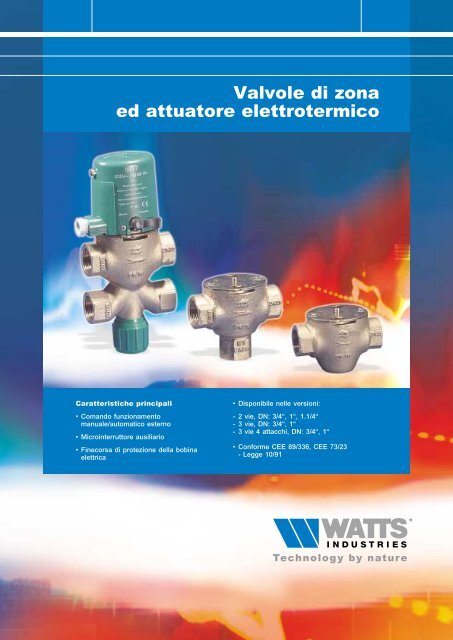
<strong>Valvole</strong> <strong>di</strong> <strong>zona</strong><br />
<strong>ed</strong> <strong>attuatore</strong> <strong>elettrotermico</strong><br />
Caratteristiche principali<br />
• Comando funzionamento<br />
manuale/automatico esterno<br />
• Microinterruttore ausiliario<br />
• Finecorsa <strong>di</strong> protezione della bobina<br />
elettrica<br />
• Disponibile nelle versioni:<br />
- 2 vie, DN: 3/4“, 1“, 1.1/4“<br />
- 3 vie, DN: 3/4“, 1“<br />
- 3 vie 4 attacchi, DN: 3/4“, 1“<br />
• Conforme CEE 89/336, CEE 73/23<br />
- Legge 10/91
VALVOLE DI ZONA<br />
Descrizione<br />
2<br />
Le valvole <strong>di</strong> regolazione <strong>zona</strong> Serie 561T, 560T, 571T sono organi automatici utilizzati generalmente per il<br />
controllo dei flussi d'acqua calda e fr<strong>ed</strong>da negli impianti <strong>di</strong> riscaldamento e/o con<strong>di</strong>zionamento, me<strong>di</strong>ante un<br />
comando elettrico ON/OFF (<strong>attuatore</strong> Serie 580T).<br />
Impiego<br />
Le valvole <strong>di</strong> <strong>zona</strong> Serie 561T, 560T, 571T sono impiegate negli impianti <strong>di</strong> :<br />
• Riscaldamento centralizzato con <strong>di</strong>stribuzione orizzontale per la regolazione e contabilizzazione del calore dei<br />
singoli appartamenti<br />
• Riscaldamento autonomo per la <strong>di</strong>visione tra <strong>zona</strong> giorno e <strong>zona</strong> notte<br />
• Con<strong>di</strong>zionamento<br />
• Distribuzione acqua calda sanitaria per intercettazione del fluido nei bollitori ad accumulo<br />
• Distribuzione industriale per l'intercettazione dei flui<strong>di</strong> nelle reti.<br />
571T<br />
Corpo valvola <strong>di</strong> <strong>zona</strong> a 2 vie.<br />
Tipo Co<strong>di</strong>ce DN Kvs<br />
571T 571T34 3/4" FF 5,5<br />
571T 571T1 1" FF 6,2<br />
571T 571T114 1.1/4" FF 7,0<br />
560T<br />
Corpo valvola <strong>di</strong> <strong>zona</strong> a 3 vie.<br />
Tipo Co<strong>di</strong>ce DN Kvs Kvs by-pass<br />
560T 560T34 3/4" FF 5,5 0 - 3,6<br />
560T 560T1 1" FF 6,2 0 - 3,6<br />
561T<br />
Corpo valvola <strong>di</strong> <strong>zona</strong> a 3 vie quattro attacchi con taratura by-pass incorporato.<br />
Tipo Co<strong>di</strong>ce DN Kvs Kvs by-pass<br />
561T 561T34 3/4" FF 5,5 0 - 3,6<br />
561T 561T1 1" FF 6,2 0 - 3,6<br />
Caratteristiche Tecniche Valvola<br />
Corpo e s<strong>ed</strong>e<br />
Stelo<br />
Otturatore<br />
Otturatore by-pass<br />
Bronzo<br />
Acciaio inox<br />
CuZn40Pb2<br />
PPE+PA<br />
Caratteristiche Costruttive Valvola<br />
Pressione <strong>di</strong> esercizio<br />
10 Bar<br />
Pressione max <strong>di</strong>fferenziale<br />
1,5 bar<br />
Temperatura <strong>di</strong> esercizio 110°C<br />
Alzata nominale stelo<br />
4 mm
VALVOLE DI ZONA<br />
566T<br />
Valvola <strong>di</strong> taratura per by-pass.<br />
3<br />
Tipo Co<strong>di</strong>ce DN<br />
566T 566T34X 3/4" FF<br />
566T 566T1X 1" FF<br />
565T<br />
Eccentrici <strong>di</strong> collegamento in tre pezzi interasse 16 mm.<br />
Tipo Co<strong>di</strong>ce DN<br />
565T 565T3434X 3/4" x 3/4"<br />
565T 565T341X 1" x 3/4"<br />
565T 565T134X 1" x 1"<br />
565T 565T11X 3/4" x 1"<br />
531C<br />
Eccentrici <strong>di</strong> collegamento in tre pezzi interasse 6 mm.<br />
Tipo Co<strong>di</strong>ce DN<br />
531C 5310C 3/4" x 3/4"<br />
531C 5311C 1" x 3/4"<br />
531C 5312C 1" x 1"<br />
531C 5313C 3/4" x 1"<br />
580T<br />
Attuatore <strong>elettrotermico</strong>.<br />
Tipo Co<strong>di</strong>ce Alimentazione Protezione<br />
580T 580T220VX 230V IP20<br />
580T 580T24VX 24V IP20<br />
Caratteristiche Tecniche Attuatore (Art. 580T)<br />
Marcatura<br />
CE EMC Compatibilità elettromagnetica<br />
Motore<br />
Elettrico ad espansione termica<br />
Portata contatto ausiliario<br />
700 mA<br />
Potenza assorbita<br />
20 W<br />
Temperatura max ambiente<br />
0-50°C<br />
Umi<strong>di</strong>tà ambiente<br />
90% U.R.<br />
Grado <strong>di</strong> protezione IP 20<br />
Tipo <strong>di</strong> regolazione<br />
ON/OFF<br />
Tempo <strong>di</strong> risposta<br />
4 min<br />
Comando<br />
Manuale apertura all' 80% della corsa<br />
Innesto sul corpo valvola<br />
A baionetta<br />
Passacavo<br />
9 mm<br />
Carena<br />
Termoplastico estinguente
VALVOLE DI ZONA<br />
Funzionamento<br />
VALVOLA<br />
4<br />
Il funzionamento delle valvole <strong>di</strong> regolazione <strong>zona</strong> Serie 561T, 560T, 571T avviene me<strong>di</strong>ante il movimento<br />
dell'otturatore che intercetta il fluido termovettore.<br />
La valvola <strong>di</strong> <strong>zona</strong> in con<strong>di</strong>zioni <strong>di</strong> riposo è normalmente chiusa. L'azionamento ON/OFF dell'otturatore della<br />
valvola <strong>di</strong> <strong>zona</strong> è affidato ad un elemento termostatico a cera presente all'interno degli attuatori Serie 580T<br />
attivato da una resistenza elettrica a fronte <strong>di</strong> un segnale emesso da un termostato ambiente (o cronotermostato).<br />
Quando riceve il consenso dal <strong>di</strong>spositivo <strong>di</strong> comando (termostato o cronotermostato), la resistenza elettrica, per<br />
effetto del passaggio <strong>di</strong> corrente, genera calore. La pillola <strong>di</strong> rame, riscaldandosi, consente all’elemento sensibile in<br />
essa contenuta <strong>di</strong> <strong>di</strong>latarsi e <strong>di</strong> esercitare la spinta sull’asta mobile provocando il movimento dell’otturatore del corpo<br />
valvola. Le caratteristiche idrauliche <strong>di</strong> portata e <strong>di</strong> per<strong>di</strong>te <strong>di</strong> carico delle valvole sono rilevabili su appositi<br />
nomogrammi: in abbinamento con gli attuatori ON/OFF invece assumono le caratteristiche proprie <strong>di</strong> tale <strong>di</strong>spositivo.<br />
Per consentire il bilanciamento idraulico degli impianti dove è previsto l’uso <strong>di</strong> valvole <strong>di</strong> <strong>zona</strong> a 3 vie è possibile<br />
utilizzare le valvole <strong>di</strong> taratura Serie 566T, installabili sulla via <strong>di</strong> miscelazione.<br />
Taratura del by-pass delle valvole serie 561T e 566T<br />
La taratura del by-pass si effettua con le seguenti operazioni :<br />
1 - Chiudere completamente il volantino<br />
2 - Togliere il volantino svitando la vite <strong>di</strong> fermo<br />
3 - Pretarare la valvola rimettendo il volantino con il riferimento<br />
riportato sulla parte interna in corrispondenza del<br />
numero prescelto sul nomogramma<br />
4 - Aprire completamente la valvola che verrà a trovarsi<br />
nella posizione desiderata.<br />
Valori <strong>di</strong> Kv per by-pass ( 566T )<br />
Posizioni <strong>di</strong> taratura 1 2 3 4 A<br />
Kv 1.4 2 2.4 2.7 3<br />
Svitare<br />
Girare<br />
Girare<br />
ATTUATORE<br />
L'<strong>attuatore</strong> <strong>elettrotermico</strong> Serie 580T è costituito da :<br />
1) Asta mobile <strong>di</strong> spinta<br />
2) Resistenza elettrica<br />
3) Pillola in rame contenente l'elemento sensibile<br />
4) Microinterruttore per comando ausiliario<br />
5) Microinterrutore <strong>di</strong> sicurezza.<br />
Peculiarità dell'<strong>attuatore</strong><br />
• Comando manuale esterno :<br />
Per l'azionamento manuale della valvola in caso <strong>di</strong> assenza d'alimentazione. Il funzionamento manuale non<br />
esclude l'eventuale sistema <strong>di</strong> contabilizzazione.<br />
• Fine corsa <strong>di</strong> protezione della resistenza elettrica :<br />
Per funzionamenti prolungati, quando la valvola è completamente aperta (bobina sotto tensione) il fine corsa<br />
interviene fornendo tensione alla bobina ad intervalli <strong>di</strong> tempo regolari.<br />
• Contatto ausiliario :<br />
Per coman<strong>di</strong> supplementari quali sistemi <strong>di</strong> contabilizzazione, pompe, ventilatori o altre apparecchiature.<br />
• Il termostato ambiente da il segnale all’<strong>attuatore</strong> 580T :<br />
l’<strong>attuatore</strong> si riscalda per la presenza <strong>di</strong> una resistenza che avvolge un cilindretto contenuto al <strong>di</strong> sotto della calotta<br />
verde. Il cilindretto contiene una sostanza che all’aumentare della temperatura si <strong>di</strong>lata andando a premere<br />
sull’asta dell’otturatore. Dopo circa 2 min (tempo necessario alla <strong>di</strong>latazione della sostanza) la valvola comincia ad<br />
aprirsi. A circa 1 mm <strong>di</strong> corsa dell’otturatore interviene il micro Aux che chiude il contatto e fa partire la pompa o il<br />
sistema <strong>di</strong> contabilizzazione. A 4 min l’otturatore è completamente aperto.<br />
• Il termostato ambiente toglie il segnale all’<strong>attuatore</strong> 580T :<br />
l’<strong>attuatore</strong> si raffr<strong>ed</strong>da e la valvola comincia a chiudere. A circa 1 mm <strong>di</strong> corsa dalla chiusura completa<br />
dell’otturatore il micro Aux apre il contatto e spegne la pompa.
VALVOLE DI ZONA<br />
Installazione<br />
Le valvole <strong>di</strong> <strong>zona</strong> devono essere installate rispettando il senso <strong>di</strong> flusso in<strong>di</strong>cato sul corpo quin<strong>di</strong> è necessario che<br />
le valvole della Serie 560T, 561T e relativo <strong>attuatore</strong> (Art. 580T), siano montate sulla tubazione <strong>di</strong> ritorno: le<br />
due bocche contrassegnate con la parola "zone", orientate verso il basso, sono così collegate al circuito secondario<br />
e grazie alla caduta <strong>di</strong> fluido dall’alto si impe<strong>di</strong>sce il deposito <strong>di</strong> residui sulla s<strong>ed</strong>e della valvola (autopulente).<br />
Il modello a 3 vie 4 attacchi, (Art. 561T+580T), per mezzo degli eccentrici (Serie 5310C-5313C) può essere<br />
collegata a monte dei collettori complanari Modul: gli eccentrici in tre pezzi adattano l'interasse della valvola (60 mm)<br />
con l'interasse dei collettori complanare Dn 3/4” (50 mm), Dn 1” (60 mm).<br />
5<br />
Evitare l'installazione della valvola con l'<strong>attuatore</strong> rivolto in basso.<br />
• La testina <strong>di</strong> comando può essere piombata al fine <strong>di</strong> evitare manomissioni.<br />
• Per smontare l'<strong>attuatore</strong> dal corpo valvola è sufficiente una breve rotazione della stessa in senso antiorario.<br />
• Togliere l'alimentazione prima <strong>di</strong> rimuovere l'<strong>attuatore</strong>.<br />
Schemi <strong>di</strong> collegamento<br />
Fig. 1<br />
Leva esterna per conversione da manuale<br />
ad automatico<br />
Fig. 2<br />
Collegamento alla morsettiera<br />
1<br />
2<br />
5<br />
6<br />
4<br />
3<br />
1-2 Porta fusibile <strong>di</strong> sicurezza per circuito<br />
primario.<br />
3 Trasformatore 230/24 V, 50 Hz<br />
(20 VA per ciascuna valvola).<br />
4 Fusibili <strong>di</strong> sicurezza per circuito<br />
secondario (0,8 A per valvola).<br />
5 Termostato<br />
6 Valvola <strong>di</strong> <strong>zona</strong>.<br />
7 Comando ausiliario per pompa,<br />
contabilizzazione.<br />
1) Elemento elettrotermostatico<br />
2) Morsetteria <strong>di</strong> collegamento<br />
3) Otturatore a tenuta metallica<br />
4) Valvola <strong>di</strong> by-pass<br />
5) Microinterruttori<br />
6) Stelo della valvola
VALVOLE DI ZONA<br />
Schemi idraulici<br />
• Le valvole <strong>di</strong> <strong>zona</strong> a 2 vie Serie 571T hanno la funzione d’intercettare il flusso termovettore ( Schema 1 ).<br />
6<br />
• Le valvole <strong>di</strong> <strong>zona</strong> a 3 Vie Serie 560T hanno la funzione d’intercettare il flusso termovettore sulla <strong>zona</strong> primaria<br />
e <strong>di</strong> deviare il flusso stesso ad un impianto derivato ( Schema 2 ).<br />
• Le valvole <strong>di</strong> <strong>zona</strong> a 3 Vie 4 attacchi Serie 561T hanno la funzione d’intercettare il flusso termovettore sulla <strong>zona</strong><br />
primaria e <strong>di</strong> deviare il flusso stesso ad un impianto derivato. Inoltre questa serie è provvista <strong>di</strong> <strong>di</strong>spositivo <strong>di</strong><br />
by-pass che consente <strong>di</strong> effettuare un bilanciamento idraulico negli impianti a più zone ( Schema 3 ).<br />
Schema 1<br />
Schema 2<br />
Schema 3
VALVOLE DI ZONA<br />
Dimensioni d’ingombro (mm)<br />
571T<br />
560T<br />
7<br />
B<br />
B<br />
C<br />
C<br />
A<br />
A<br />
Co<strong>di</strong>ce DN A B C<br />
571T 3/4" 90 61 25<br />
571T 1" 100 61 25<br />
571T 1.1/4" 103 59 25<br />
Co<strong>di</strong>ce DN A B C<br />
560T 3/4" 90 78 25<br />
560T 1" 100 78 25<br />
561T<br />
566T<br />
C<br />
B<br />
B<br />
C<br />
25<br />
A<br />
A<br />
Co<strong>di</strong>ce DN A B C<br />
561T 3/4" 90 130 50<br />
561T 1" 100 140 60<br />
Co<strong>di</strong>ce DN A B C<br />
566T 3/4" 90 130 50<br />
566T 1" 100 140 60<br />
580T<br />
62<br />
73<br />
88
VALVOLE DI ZONA<br />
Nomogrammi portate/per<strong>di</strong>te <strong>di</strong> carico<br />
8<br />
Massime aperture<br />
561T - 560T - 571T DN 3/4" - 1" - 1.1/4"<br />
DN 1.1/4" Kvs 7.8<br />
DN 1" Kvs 6.8<br />
DN 3/4" Kvs 5.5<br />
[ kPa ]<br />
[ m bar ] [ mm c.a. ]<br />
20<br />
200<br />
2000<br />
10<br />
8<br />
100<br />
80<br />
1000<br />
800<br />
PERDITE DI CARICO<br />
5<br />
4<br />
3<br />
2<br />
1<br />
0.8<br />
0.5<br />
50<br />
40<br />
30<br />
20<br />
10<br />
5<br />
500<br />
400<br />
300<br />
200<br />
100<br />
50<br />
0.3<br />
3<br />
30<br />
0.2<br />
2<br />
20<br />
0.1<br />
1<br />
3000<br />
20 30 50 100<br />
10 200 300 500 1000 2000<br />
[ l/h ]<br />
10<br />
0.01 0.02 0.03 0.05 0.1 0.2 0.3 0.5 1 2 3<br />
3<br />
[ m /h ]<br />
PORTATE<br />
Taratura by-pass<br />
560T - 571T<br />
pos 3 Kv 1.5<br />
pos 2.5 Kv 1.2<br />
pos 2 Kv 0.9<br />
pos 1.5 Kv 0.8<br />
pos 3.5 Kv 2.0<br />
pos 4 Kv 2.5<br />
pos 4.5 Kv 3.0<br />
pos A Kv 3.8<br />
[ kPa ]<br />
pos 1 Kv 0.6<br />
[ m bar ] [ mm c.a. ]<br />
20<br />
200<br />
2000<br />
10<br />
8<br />
100<br />
80<br />
1000<br />
800<br />
PERDITE DI CARICO<br />
5<br />
4<br />
3<br />
2<br />
1<br />
0.8<br />
0.5<br />
50<br />
40<br />
30<br />
20<br />
10<br />
5<br />
500<br />
400<br />
300<br />
200<br />
100<br />
50<br />
0.3<br />
3<br />
30<br />
0.2<br />
2<br />
20<br />
0.1<br />
1<br />
3000<br />
20 30 50 100<br />
10 200 300 500 1000 2000<br />
[ l/h ]<br />
10<br />
0.01 0.02 0.03 0.05 0.1 0.2 0.3 0.5 1 2 3<br />
3<br />
[ m /h ]<br />
PORTATE<br />
Le descrizioni e le fotografie contenute nel presente, si intendono fornite a semplice titolo informativo e non impegnativo.<br />
Watts Cazzaniga si riserva il <strong>di</strong>ritto <strong>di</strong> apportare, senza alcun preavviso, qualsiasi mo<strong>di</strong>fica tecnica <strong>ed</strong> estetica ai propri prodotti.<br />
WATTS Cazzaniga S.p.A.<br />
Via Parco, 20046 Biassono (MI), Italia<br />
Tel. 039 49 86.1 - Fax 49 86.222<br />
E-mail info@wattscazzaniga.it<br />
Sito www.wattsindustries.com<br />
Re-order no. 01F051-IT/1-04-09-Rev. 0