caution - Tekno Point
caution - Tekno Point
caution - Tekno Point

You also want an ePaper? Increase the reach of your titles
YUMPU automatically turns print PDFs into web optimized ePapers that Google loves.
MANUALE UTENTE – INSTALLATORE<br />
USER’S – INSTALLER'S MANUAL<br />
MULTI DC INVERTER UNITS<br />
CANALIZZATO - DUCTED TYPE<br />
2600 W<br />
3600 W<br />
5300 W<br />
SOFFITTO PAVIMENTO - FLOOR CEILING<br />
3600 W<br />
5300 W<br />
Questo manuale è stato creato per scopo informativo. La ditta declina ogni responsabilità per i risultati di una progettazione o di una installazione<br />
basata sulle spiegazioni e le specifiche tecniche riportate in questo manuale. E’ inoltre vietata la riproduzione anche parziale sotto qualsiasi forma<br />
dei testi e delle figure contenute in questo manuale.<br />
This manual has been created for informative purpose. The company declines every responsibility for the results of projecting or installation based on<br />
the explanations and the technical specifications given in this manual. Is besides forbidden the reproduction under any form of the texts and of the<br />
figures contained in this manual.
Serie / Series / Serie / Serie<br />
MANUALE UTENTE – INTALLATORE<br />
MULTI DC INVERTER CANALIZZATI- SOFF.-PAV.<br />
USER’S - INSTALLATION MANUAL<br />
MULTI DC INVERTER DUCT- FLOOR-CEILING<br />
Emissione / Issue<br />
Ausgabe / Emission<br />
02 - 2009<br />
Sostituise / Supersade<br />
Ersetzt / Remplace<br />
-<br />
Catalogo / Catalogue / Katalog / Catalogue<br />
MUI1402090401-00<br />
I prodotti elettrici ed elettronici di eventuale scarto non dovranno essere<br />
disposti con i normali rifiuti domestici, ma smaltiti a norma di legge RAEE in<br />
base alle direttive Europee 2002/96/CE e suc-cessive modifiche<br />
2003/108/CE, informandosi presso il Comune di residenza o presso il<br />
rivenditore nel caso in cui il prodotto venga sostituito con uno analogo.<br />
Possible wasted electrical or electronic devices/products should not be<br />
located together with normal domestic waste, but disposed according to the<br />
current WEEE law in compliance with the European Directive 2002/96/EC<br />
and following modifications 2003/108/EC. Please inform yourself at your<br />
local Administration or at your reseller in case the product will be replaced<br />
with a similar one.<br />
2
ITALIANO<br />
3
INDICE<br />
I. DESCRIZIONE<br />
II. INFORMAZIONI IMPORTANTI<br />
III. SEZIONE DI UTILIZZO<br />
III. 1 TELECOMANDO R51.............................................................................................. 8<br />
III. 2. NOMI DEI COMPONENTI DELL’APPARECCHIO.................................................. 14<br />
III. 3. OPERAZIONI E PRESTAZIONI DEL CONDITIONATORE .................................... 14<br />
III. 4. CONSIGLI PER IL FUNZIONAMENTO ECONOMICO........................................... 15<br />
III. 5. REGOLAZIONE DEL FLUSSO DELL’ARIA............................................................ 15<br />
III. 6 PULIZIA DEL FLITRO DELL’ARIA........................................................................... 16<br />
III. 7. I SIGUENTI SINTIMI IN OGNI CASO MALFUNZIONAMENTI ............................... 16<br />
III. 8. MALFUNZIONAMENTI ........................................................................................... 18<br />
IV. SEZIONE DI INSTALLAZIONE<br />
IV. 1. PRECAUZIONI ....................................................................................................... 19<br />
IV. 2. INFORMAZIONI PER L’INSTALLAZIONE.............................................................. 19<br />
IV. 3. ACCESSORI .......................................................................................................... 19<br />
IV. 4 COMBINAZIONI DELLE UNITÀ INTERNE.............................................................. 20<br />
IV. 5. INSTALLAZIONE DELL’UNITÀ INTERNA ............................................................. 21<br />
IV. 6 INSTALLAZIONE DELL’UNITÀ ESTERNA ............................................................. 26<br />
IV. 7. SCHEMA ELETTRICO ........................................................................................... 30<br />
IV. 8. PROVA DI FUNZIONAMENTO .............................................................................. 31<br />
4
I. DESCRIZIONE<br />
UNITA’ INTERNA<br />
Aria in ingresso<br />
2<br />
1<br />
3<br />
2<br />
Aria in uscita<br />
Aria in ingresso<br />
3<br />
Aria in uscita<br />
1<br />
Aria in uscita<br />
4<br />
3<br />
5<br />
4<br />
3<br />
5<br />
8<br />
6<br />
8<br />
6<br />
9<br />
7<br />
UNITA’ ESTERNA<br />
9<br />
7<br />
UNITÀ INTERNA<br />
1 Aletta<br />
2 Gruppo ingresso aria (filtro dentro)<br />
3 Parte installazione<br />
4 Telecomando R51<br />
5 Pannello display<br />
6 Tubo di scarico condensa<br />
UNITÀ ESTERNA<br />
7 Tubo di connessione<br />
8 Cavo di connessione<br />
9 Valvola di arresto<br />
9 Ricevitore segnale infrarossi<br />
NOTA: Tutte le immagini in questo manuale sono soltanto un esempio illustrativo utile alla spiegazione e possono<br />
essere lievemente diverse dal condizionatore che avete acquistato (a seconda del modello).<br />
5
II. INFORMAZIONI IMPORTANTI<br />
Leggere interamente questo manuale per un corretto uso del condizionatore e danni alle persone ed al bene. Lo<br />
scorretto uso della macchina potrebbe causare danni o ferite.<br />
È consigliato leggere con attenzione queste informazione importanti per adeguarsi alle procedure di sicurezza.<br />
! AVVERTIMENTO<br />
Il condizionatore deve essere installato rispettando le norme di cablaggio nazionale per evitare il rischio di pericolo di morte<br />
Affidare al fornitore od a personale qualificato l’installazione.<br />
All’utente non è permesso installare da solo le unità, per evitare perdite d’acqua, scosse elettriche, incendi ecc.<br />
Contattare il fornitore od il centro assistenza più vicino per migliorare le prestazioni, riparazione o manutenzione.<br />
Per evitare prestazioni inadeguate, o rischio di perdite d’acqua, scosse elettriche ed incendi.<br />
Per evitare scosse elettriche, incendi o ferite, spegnere il condizionatore nel caso d’anomalia tale odori strani o incendi e<br />
contattare il fornitore od il centro assistenza il più vicino.<br />
Non lasciare mai l’unità ed il telecomando bagnarsi.<br />
Per evitare scosse elettriche o incendi.<br />
Non stare a lungo a diretto contatto con l’aria fredda. Aria troppo fredda può causare danni alla salute.<br />
Non usare spry infiammabili tale spray per capelli, vernice vicino all’unità.<br />
Ciò potrebbe causare incendi.<br />
Mai mettere le mani nello sbocco d’uscita d’aria o sulle alette orizzontali quando esse sono in movimento.<br />
Per evitare il rischio di catturarsi le mani o danneggiare il condizionatore.<br />
! PERICOLO<br />
Non provare da soli a fornire assistenza alla macchina. Questa unità non ha elementi di utilizzo che devono essere aperti e la<br />
rimozione del coperchio può esporvi a pericolosi voltaggi. Togliere l’ alimenta-zione non basta ad evitare possibili shock elettrici.<br />
! PERICOLO<br />
Mai mettere le mani o oggetti nello sbocco d'entrata e uscita dell'unità. Questa unità contiene una ventola che gira ad alta velocità.<br />
Un contatto con essa può causa-re serie lesioni.<br />
! PERICOLO<br />
Per evitare il rischio di serie scariche elettriche, mai spruzzare o versare acqua o altri liquidi nell'unità.<br />
! ATTENZIONE<br />
Ventilare la stanza ogni tanto mentre il condizionatore è in funzione, specialmente se ci sono altre apparecchiature a gas in uso<br />
nella stanza. Non seguire questi consigli può causare una perdita di ossigeno nella stanza.<br />
! ATTENZIONE<br />
Per prevenire una scarica elettrica, spe-gnere la corrente o staccare la spina prima di iniziare ogni pulizia o altre varie<br />
manutenzioni. Seguire le indicazioni perla pulizia nel manuale utente.<br />
! ATTENZIONE<br />
Non usare liquidi o aerosol per la pulizia. Usare un soffice e asciutto panno per pulire l'unità. Per evitare scariche elet-triche, mai<br />
provare a pulire l'unità spruz-zando acqua su di essa.<br />
! PRECAUZIONI<br />
Non usare detergenti nell'unità. I solventi pos-sono velocemente distruggere gli elementi dell'unità (vaschetta di scarico e gli<br />
elementi dello scambiatore di calore).<br />
NOTE<br />
Per un'adeguata prestazione, utilizzare l'unità sotto la temperatura operativa e le condizioni d'umidità indicate nel questo Manuale.<br />
Se l'unità è utilizzata al di fuori di queste indicazioni, questo può causare malfunzionamenti dell'unità o gocciolamento dall'unità<br />
interna.<br />
Mantenere la temperatura della stanza a un livello confortevole.<br />
Pulizia del filtro dell'aria<br />
Un filtro dell'aria intasato, riduce la poten-za di raffreddamento. Pulirlo ogni due settimane.<br />
Mai aprire porte e finestre oltre ciò che è necessario<br />
Per mantenere fresca o calda l'aria nella stanza, mai aprire porte e finestre oltre ciò che è necessario.<br />
Tende<br />
In raffreddamento, chiudere le tende per evitare la luce solare diretta.<br />
Rendere uniforme la circolazione dell'aria nella stanza<br />
Sistemare la direzione del flusso d'aria per ogni circolazione nella stanza.<br />
6
! AVVERTIMENTO<br />
Non installare l’unità da soli.<br />
Un’installazione errata può provocare ferite dovute ad incendi, folgorazioni, cadute dell'unità o perdite d’acqua. Contattare il<br />
fornitore dal quale avete acquistato l'unità o un’ installatore speciale.<br />
L’installazione deve essere conforme alle istruzioni indicate.<br />
L'installazione errata può provocare ferite dovute ad incendi, folgorazioni, cadute dell'unità o perdite d’acqua.<br />
Installare saldamente l'unità su di un supporto che può sopportarne il peso.<br />
Installare su un supporto debole può provocarne il cedimento e quindi ferite dovute alla caduta dell’unità.<br />
Realizzare i collegamenti elettrici rispettando le normative nazionale e gli schemi di cablaggio elettrico di questo<br />
manuale ed assicurarsi di utilizzare un circuito elettrico individuale.<br />
Se la capacità del circuito di alimentazione è insufficiente, potrebbe manifestarsi un incendio o una scarica elettrica.<br />
Usare i cavi specifici per i cablaggi elettrici ed eseguire i collegamenti correttamente.<br />
Collegamenti errati possono causare incendi.<br />
Controllare che non ci siano perdite di gas refrigerante dopo l’installazione<br />
Assicurarsi di usare le parti fornite e specificate, durante l’installazione.<br />
L'uso di pezzi difettosi può provocare ferite dovute ad incendi,folgorazioni ecc.<br />
Fissare saldamente il coperchio che isola la parte elettrica delle unità.<br />
Se le coperture elettriche delle unità non sono fissate saldamente, potrebbero manifestarsi incendi o scariche elettriche causate<br />
da polvere, acqua ecc.<br />
! ATTENZIONE<br />
Non installare l'unità in luoghi dove possano propagarsi gas infiammabili.<br />
L’unità potrebbe incendiare il gas propagatosi e provocare un’esplosione.<br />
Le unità interne dovrebbero essere installate:<br />
In un luogo dove c’è sufficiente spazio per l’installazione e la manutenzione.<br />
■ In un luogo in cui il flusso d’aria possa raggiungere tutti gli angoli.<br />
■ In un luogo dove le tubazioni e lo scarico condensa possano essere raggiunte facilmente.<br />
■ In un luogo dove non vi siano perdite gas infiammabili o nocivi/corrosivi. in un luogo dove non vi sia l’effetto di elevate tensioni<br />
e alte frequenze.<br />
■ In un luogo in cui non vi siano rumore o l’effetto di vibrazioni.<br />
! CUTELE<br />
Il posizionamento nei seguenti luoghi può causare malfunzionamenti. (Se non si può evitare, contattare il fornitore<br />
locale)<br />
■ Luoghi con presenza di olio minerale,<br />
■ Luoghi in cui l’aria possa essere ricca di salsedine, come nelle vicinanze di spiagge.<br />
■ Luoghi con presenza di zolfo.<br />
■ Luoghi in cui ci sono forti variazioni della tensione.<br />
■ Luoghi in cui vi può essere gas naturale-etano, come le cucine.<br />
■ Luoghi in cui ci siano fenomeni elettromagnetici legati ad alte frequenze.<br />
■ Luoghi in cui vi siano gas o sostanze infiammabili. h. luoghi in cui vi sono acidi o gas alcalini.<br />
■ Altri luoghi per applicazioni speciali.<br />
7
III. SEZIONE DI UTILIZZO<br />
III. 1 TELECOMANDO R51<br />
Telecomando completo di pile di alimentazione.<br />
SET TEMPERATUR (°C)<br />
AU TO<br />
COOL<br />
DRY<br />
HEAT<br />
FAN<br />
HIGH<br />
MED<br />
LOW<br />
TEMP.<br />
MODE<br />
ON/OFF FAN SPEED<br />
SWING ECONOMIC TIMER ON<br />
TIMER OFF<br />
RESETLOCK<br />
AIR DIRECTION<br />
POWERFUL<br />
III. 1.1 ISTRUZIONI DI UTILIZZAZIONE<br />
Tramite il telecomando è possibile eseguire le seguenti operazioni:<br />
• Accensione/spegnimento dell’unità.<br />
• Scelta delle tre velocità del ventilatore.<br />
• Regolazione del termostato e mantenimento in ambiente della temperatura desiderata.<br />
• Commutazione del ciclo di funzionamento: raffreddamento/riscaldamento. Sulla griglia dell’unità sono presenti degli<br />
indicatori che forniscono informazioni sullo stato dell’unità o eventuali segnalazioni di allarme e, qualora non fosse<br />
temporaneamente disponibile il telecomando e/o il pannello comando consentono, utilizzando il tasto MANUAL, di<br />
gestire l’unità in modalità manuale.<br />
III. 1.2 Telecomando<br />
Il telecomando permette di impostare e visualizzare tutti i parametri di funzionamento dell’unità, facilitando così tutte<br />
le operazioni di programmazione.<br />
Il telecomando é alimentato con 2 batterie R03 size AAA da 1,5 V.<br />
IMPORTANTE!<br />
E’ consigliabile testare il funzionamento del telecomando per determinare la sua zona di ricezione.<br />
8
III. 1.2.1 Descrizione telecomando e relative funzioni<br />
1<br />
2<br />
3<br />
4<br />
5<br />
6<br />
7<br />
SET TEMPERATURE (°C)<br />
AUTO<br />
COOL<br />
DRY<br />
HEAT<br />
TEMP.<br />
FAN<br />
HIGH<br />
MED<br />
LOW<br />
MODE ON/OFF FAN SPEED<br />
SWING<br />
AIR DIRECTION<br />
ECONOMIC TIMER ON<br />
RESET LOCK<br />
TIMER OFF<br />
POWERFUL<br />
3<br />
8<br />
9<br />
10<br />
11<br />
10<br />
12<br />
13<br />
(1) Trasmette i segnali infrarossi al ricevitore dell’unità<br />
(2) Indica gli stati e i modi di funzionamento dell’unità<br />
(3) Questi tasti permettono di impostare la temperatura ambiente desiderata.<br />
▲ la temperatura richiesta viene incrementata fino a 30 °C ,▼ la temperatura<br />
richiesta viene decrementata fino a 17 °C Ogni pressione corrisponde una<br />
variazione di 1°C.<br />
(4) Permette di selezionare il tipo di funzionamento desiderato (AUTO, COOL,<br />
DRY, HEAT, FAN).<br />
(5) Questo tasto permette al deflettore di oscillare in maniera orizzontale.<br />
(6) Premere questo pulsante per ripristinare le impostazioni del telecomando.<br />
(7) Permette di selezionare l’angolo di inclinazione del deflettore<br />
(8) Permette di accendere e spegnere l’unità. Premere il tasto per accendere,<br />
premere nuovamente per spegnere<br />
(9) Premere questo tasto per selezionare la velocità del ventilatore. Quando si<br />
seleziona AUTO la velocità del ventilatore viene regolata automaticamente a<br />
seconda della temperatura dell’ambiente. È possibile selezionare anche<br />
manualmente la velocità del ventilatore scegliendo tra 3 regolazioni: LOW =<br />
MINIMA; MED = MEDIA; HIGH = MASSIMA.<br />
(10) Premere questi tasti per predisporre lo spegnimento/accensione dell’unità<br />
con timer.<br />
(11) Premere questo tasto per un funzionamento favorire il risparmio di<br />
energia.<br />
(12) Permette di bloccare ogni funzionalità del telecomando.<br />
(13) Premere questo tasto durante il funzionamento in raffreddamento<br />
(riscaldamento) per cambiare al funzionamento di raffreddamento<br />
(riscaldamento) forzato. Premere di nuovo lo stesso tasto per cancellare<br />
questa funzione.<br />
III. 1.2.2 Descrizione del display<br />
1<br />
2<br />
4<br />
3<br />
2<br />
8<br />
5<br />
TIMERONOFF<br />
6,7<br />
1) Indicatore di trasmissione: Appare ogni volta che si trasmette un segnale all’unità interna.<br />
2) Visualizzazione del programma di funzionamento (MODE). Indica il tipo di funzionamento prescelto.<br />
3) Visualizzazione ON/OFF: Indica che l’unità è in funzione.<br />
4) Visualizzazione della temperatura (TEMP): Indica la temperatura impostata (da 17 °C a 30 °C). Quando si sceglie il<br />
programma di funzionamento FAN non viene visualizzata nessuna temperatura.<br />
5) Visualizzazione di blocco: Indica che il telecomando è bloccato.<br />
6) Visualizzazione del timer (TIMER ON). Se si preme il tasto TIMER viene visualizzato l’orario di accensione con<br />
timer.<br />
7) Visualizzazione del timer: Se si preme il tasto TIMER OFF viene visualizzato l’orario di spegnimento con timer.<br />
8) Visualizzazione della velocità del ventilatore (FAN) Indica la velocità del ventilatore selezionata. Può essere<br />
visualizzato AUTO o uno dei tre livelli di velocità: MINIMA (LOW), MEDIA (MED), MASSIMA (HIGH).<br />
9
III. 1.2.3 Uso del telecomando<br />
Il telecomando utilizza due batterie alcaline da 1,5 V del tipo R03 size AAA (fornite in dotazione). Per inserire le<br />
batterie, sfilare completamente il coperchio del telecomando facendolo slittare verso la parte inferiore. Inserire le<br />
batterie nell’apposito alloggiamento rispettando le polarità indicate. Riposizionare il coperchio e selezionare le<br />
funzioni desiderate. Stessa operazione deve essere fatta per la sostituzione delle batterie scariche con altre batterie<br />
nuove. La durata media delle batterie é di circa un anno.<br />
Il telecomando rimane sempre con il display acceso. Rimuovere le batterie dal telecomando se si prevede di non<br />
utilizzarlo per lunghi periodi.<br />
Rivolgere il telecomando verso il ricevitore dell’unità mentre si effettuano le impostazioni. Se i segnali vengono<br />
ricevuti correttamente, l’unità emetterà un segnale acustico “beep”. Il telecomando è in grado di trasmettere fino ad<br />
una distanza di circa 11 metri dal ricevitore.<br />
Evitare l’esposizione del telecomando all’umidità eccessiva, alla luce solare diretta o ad altre fonti di calore ed evitare<br />
gli urti. Proteggere il telecomando dall’acqua o altri liquidi. Se il ricevitore a raggi infrarossi dell’unità è esposto a luce<br />
solare diretta o a luce intensa di una lampada oppure nelle vicinanze è presente una lampada fluorescente con<br />
accensione elettronica, l’unità potrebbe presentare anomalie di funzionamento o non funzionare. L’utilizzo di altri<br />
telecomandi nelle vicinanze o nello stesso ambiente in cui é installata l’unità potrebbe influenzarne il regolare<br />
funzionamento; evitare di rivolgere il trasmettitore di altri telecomandi verso il ricevitore dell’unità.<br />
III. 1.2 ACCENSIONE SPEGNIMENTO DELL’UNITÀ<br />
ON/OFF<br />
Premere il tasto ON/OFF per accendere o spegnere l’unità.<br />
Nel passaggio da ON a OFF viene interrotto qualsiasi modalità di funzionamento, cancellate le temporizzazioni in<br />
corso, memorizzati la modalità di funzionamento dell’apparecchio e del ventilatore ed il valore di temperatura<br />
impostato. Nel passaggio da OFF a ON l’unità ripristina automaticamente tutte le modalità di funzionamento<br />
memorizzate prima dello spegnimento.<br />
Ad unità accesa sul display compare l’indicazione di unità accesa.<br />
La presenza di questo simbolo sul display indica che il telecomando sta trasmettendo le impostazioni all’unità. ▲<br />
III. 1.3 IMPOSTAZIONE DELLA MODALITÀ DI FUNZIONAMENTO<br />
Premendo più volte il tasto Mode è possibile cambiare la modalità di funzionamento dell’unità. Sul display compare<br />
l’indicazione della modalità di funzionamento selezionato:<br />
AUTO: funzionamento completamente automatico<br />
COOL: funzione raffreddamento<br />
DRY: funzione deumidificazione<br />
HEAT: funzione riscaldamento<br />
FAN: funzionamento solo ventilazione<br />
Con la scelta della modalità AUTO, l’unità può operare in RAFFREDDAMENTO ed in RISCALDAMENTO in base alla<br />
differenza di temperatura esistente tra la temperatura ambiente e la temperatura selezionata sul telecomando.<br />
Quando viene scelta la modalità di raffreddamento COOL, l’unità funziona con set di temperatura libero, abbassando la<br />
temperatura in ambiente.<br />
Quando viene scelto la modalità di deumidificazione DRY, l’unità funziona, con set di temperatura libero, abbassando<br />
così progressivamente la temperatura e l’umidità in ambiente. Nella modalità di deumidificazione DRY il tasto FAN<br />
SPEED non è utilizzabile.<br />
10
Quando viene scelto il programma di riscaldamento HEAT, l’unità funziona, con set di temperatura libero, alzando la<br />
temperatura in ambiente. Quando viene scelto il programma di ventilazione FAN, l’unità funziona senza set di<br />
temperatura, ventilando l’aria dell’ambiente.<br />
IMPORTANTE!<br />
- Il ventilatore dell’unità si ferma al raggiungimento del valore di temperatura impostato per poi riattivarsi<br />
automaticamente alla velocità minima per evitare fenomeni di stratificazione dell’aria in prossimità dell’apparecchio.<br />
- Selezionando la funzione COOL DRY, il ventilatore potrebbe non avviarsi subito perché presente la funzione<br />
ANTI-HEATING. Selezionando la funzione HEAT, il ventilatore potrebbe non avviarsi subito perché presente la<br />
funzione ANTI-COOLING.<br />
III. 1.4 FUNZIONE ECONOMY<br />
ECONOMIC<br />
Usare questa funzione per un funzionamento favorire il risparmio di energia.<br />
III. 1.5 IMPOSTAZIONE DELLA TEMPERATURA DESIDERATA<br />
▲e▼Premendo questi tasti nelle modalità AUTO, COOL, DRY, HEAT è possibile aumentare o diminuire il valore<br />
della temperatura desiderata tra 17°C e 30°C. Il display visualizza il valore della temperatura selezionato.<br />
III. 1.6 IMPOSTAZIONE DEL DEFLETTORE<br />
Per ottenere una distribuzione ottimale dell’aria, regolare la posizione del deflettore motorizzato avendo cura che il<br />
flusso d’aria non investa direttamente le persone. Per il deflettore motorizzato agire nella modalità seguente:<br />
AIR<br />
DIRECTION<br />
Premendo più volte il tasto AIR DIRECTION è possibile modificare la posizione del deflettore.<br />
SWING<br />
Premendo il tasto SWING è possibile attivare l’oscillazione continua del deflettore.<br />
PERICOLO!<br />
Muovere manualmente il deflettore motorizzato quando l’unità è accesa potrebbe causare dei problemi di<br />
funzionamento o danneggiare il sistema di regolazione.<br />
III. 1.7 IMPOSTAZIONE DELLA VENTILAZIONE<br />
Premendo più volte il tasto FAN SPEED è possibile impostare la velocità del ventilatore tra le tre disponibili, oppure<br />
attivare la funzione AUTO. Sul display compare la modalità di funzionamento:<br />
AUTO: funzionamento completamente automatico.<br />
LOW: funzionamento velocità minima.<br />
MED: funzionamento velocità media.<br />
HIGH: funzionamento velocità massima<br />
III. 1.8 IMPOSTAZIONE DEI TIMER<br />
IMPORTANTE!<br />
Affinché le impostazioni del timer abbiano effetto, il telecomando deve essere SEMPRE posizionato nei pressi<br />
dell’unità (ad una distanza massima di 11 metri) e rivolto verso la stessa.<br />
La funzione TIMER non è ripetitiva e deve essere impostata ogni qualvolta si desidera utilizzarla. Quando viene<br />
selezionata la funzione Timer ON-OFF, l'accensione dell'unità potrà avvenire con un leggero ritardo rispetto all'orario<br />
timer programmato, ciò è da ritenersi del tutto normale e rientra nel corretto funzionamento dell'unità.<br />
TIMER ON e TIMER OFF: Premendo questo tasto è possibile programmare l’orario di accensione e/o l’orario di<br />
spegnimento dell’unità.<br />
11
▲e▼: Premendo questo tasto è possibile modificare l’orario di accensione o di spegnimento. Ad ogni pressione del<br />
tasto l’orario viene incrementato o decrementato di 0.5h prima di 10H dopodichè il differenziale dell’impostazione<br />
timer aumenta di 1h in ogni pressione del tasto ▲.<br />
III. 1.9 BLOCCO DELLA TASTIERA<br />
Premendo con un oggetto appuntito il tasto BLOCCO/LOCK è possibile inibire completamente la<br />
tastiera del telecomando evitando usi indesiderati dello stesso (bambini, ecc.). Il display visualizzerà il<br />
simbolo riportato a fianco. Per rimuovere il blocco della tastiera, premere nuovamente con un oggetto<br />
appuntito il tasto BLOCCO/LOCK.<br />
III. 1.10 RESET DEL TELECOMANDO<br />
Premendo con un oggetto appuntito il tasto RESET è possibile riportare il telecomando alle impostazioni di<br />
fabbrica.<br />
III. 1.11 GUIDA RAPIDA AL FUNZIONAMENTO<br />
SET TEMPERATURE (°C)<br />
AUTO<br />
COOL<br />
DRY<br />
HEAT<br />
FAN<br />
HIGH<br />
MED<br />
LOW<br />
TEMP.<br />
2<br />
1<br />
5<br />
MODE ON/OFF FAN SPEED<br />
SWING<br />
ECONOMIC TIMER ON<br />
RESET LOCK<br />
TIMER OFF<br />
4<br />
3<br />
6<br />
AIR DIRECTION<br />
POWERFUL<br />
III. 1.11.1 FUNZIONAMENTO AUTOMATICO<br />
Con la scelta della modalità AUTO l’unità può operare in RAFFREDDAMENTO o in RISCALDAMENTO in base alla<br />
differenza di temperatura esistente tra la temperatura ambiente e la temperatura selezionata sul telecomando.<br />
L’unità funzionerà in Condizione<br />
Raffreddamento TA - TS > 1 °C<br />
Ventilazione -1 °C ≤ TA - TS ≤ 1 °C<br />
Riscaldamento<br />
TA - TS < -1 C<br />
TA = Temperatura ambiente, TS = Temperatura selezionata<br />
III. 1.11.2 MODALITÀ RAFFREDDAMENTO<br />
Per impostare la modalità di raffreddamento COOL procedere come segue:<br />
• Selezionare la modalità COOL, agendo sul tasto MODE (1);<br />
• regolare la temperatura desiderata premendo i tasti TEMP (2) il display indica valori da 17 °C a 30 °C;<br />
• regolare la velocità di ventilazione premendo il tasto FAN SPEED (3), scegliendo tra AUTO e le altre velocità HIGH-<br />
MED-LOW;<br />
12
• rivolgere il telecomando verso il ricevitore dell’unità, e premere il tasto di accensione ON/OFF (4);<br />
• regolare il flusso dell’aria secondo le esigenze utilizzando il tasto SWING (5) o AIR DIRECTION (6). Fatte le<br />
regolazioni, queste verranno riproposte quando si riaccenderà l’unità.<br />
Ogni segnale trasmesso dal telecomando, se ricevuto dall’unità, viene confermato da un “beep”.<br />
III. 1.11.3 FUNZIONE DEUMIDIFICAZIONE<br />
Per impostare la modalità deumidificazione DRY procedere come segue:<br />
• Selezionare la modalità DRY, agendo sul tasto MODE (1);<br />
• regolare la temperatura desiderata premendo i tasti TEMP (2) il display indica valori da 17 °C a 30 °C;<br />
• rivolgere il telecomando verso il ricevitore dell’unità, e premere il tasto di accensione ON/OFF (4);<br />
• regolare il flusso dell’aria secondo le esigenze utilizzando il tasto SWING (5) o AIR DIRECTION (6); Fatte le<br />
regolazioni, queste verranno riproposte quando si riaccenderà l’unità.<br />
Ogni segnale trasmesso dal telecomando, se ricevuto dall’unità, viene confermato da un “beep”.<br />
Quando viene scelta la modalità di deumidificazione DRY, l’unità funziona con set di temperatura libero, abbassando<br />
così progressivamente la temperatura e l’umidità in ambiente.<br />
Nella modalità di deumidificazione DRY, il tasto FAN SPEED non è utilizzabile.<br />
III. 1.11.4 FUNZIONE RISCALDAMENTO<br />
Per impostare la modalità di riscaldamento HEAT procedere come segue:<br />
• Selezionare la modalità HEAT, agendo sul tasto MODE (1);<br />
• regolare la temperatura desiderata premendo i tasti TEMP (2): il display indica valori da 17°C a 30°C;<br />
• regolare la velocità di ventilazione agendo sul tasto FAN SPEED (3), scegliendo tra AUTO e le altre velocità HIGH-<br />
MED-LOW;<br />
• rivolgere il telecomando verso il ricevitore dell’unità, e premere il tasto di accensione ON/OFF (4);<br />
• regolare il flusso dell’aria secondo le esigenze utilizzando il tasto SWING (5) o AIR DIRECTION (6). Fatte le<br />
regolazioni, queste verranno riproposte quando si riaccenderà l’unità.<br />
Ogni segnale trasmesso dal telecomando, se ricevuto dall’unità, viene confermato da un “beep”.<br />
III. 1.11.5 FUNZIONE VENTILAZIONE<br />
Per impostare la modalità di ventilazione FAN procedere come segue:<br />
• Selezionare la modalità FAN, agendo sul tasto MODE (1),<br />
• regolare la velocità di ventilazione agendo sul tasto FAN SPEED (3), scegliendo tra AUTO e le altre velocità HIGH-<br />
MED-LOW;<br />
• rivolgere il telecomando verso il ricevitore dell’unità, e premere il tasto di accensione ON/OFF (4);<br />
• regolare il flusso dell’aria secondo le esigenze utilizzando il tasto SWING (5) o AIR DIRECTION (6); Fatte le<br />
regolazioni, queste verranno riproposte quando si riaccenderà l’unità.<br />
Ogni segnale trasmesso dal telecomando, se ricevuto, viene confermato da un suono “beep”.<br />
13
III. 2. NOMI DEI COMPONENTI DELL’APPARECCHIO<br />
Il condizionatore è composto d’un unità interna, unità esterna, tubazioni di collegamento e di un telecomando.<br />
(Riferirsi alla Fig-2-1)<br />
■ Descrizione degli indicatori sul display dell’unità interna<br />
OPERATION AUTO TIMER<br />
PRE.-DEF.<br />
Fig.2-1<br />
NOTA: Tutte le immagini in questo manuale sono soltanto un esempio illustrativo utile alla spiegazione e possono<br />
essere lievemente diverse dal condizionatore che avete acquistato (a seconda del modello).<br />
• Il LED OPERATION lampeggia una volta per secondo dopo aver connesso l’alimentazione.<br />
• Il LED OPERATION sulla prima unità in operazione lampeggia per due volte per secondo mentre il LED della<br />
successiva unità in operazione rimarrà acceso durante il periodo di funzionamento.<br />
• Il LED OPERATION rimarrà spento quando il condizionatore è spento.<br />
• Il LED del TIMER rimarrà acceso quando il Timer On/Off viene impostato.<br />
• Il LED DEF rimarrà acceso durante il funzionamento di sbrinamento ed il raffreddamento.<br />
• Il LED DEF rimarrà spento durante il funzionamento di ventilazione per qualsiasi velocità di funzionamento (ALTA,<br />
MEDIA, BASSA).<br />
• I LED TIMER e DEF lampeggiano per 5 volte per secondo nell’avvenimento di conflitto di modalità.<br />
• I LED OPERATION e DEF lampeggiano per 5 volte per secondo durante il funzionamento in fase di massimo<br />
raffreddamento.<br />
III. 3. OPERAZIONI E PRESTAZIONI DEL CONDITIONATORE<br />
Per un'adeguata prestazione e per un funzionamento sicuro, utilizzare l'unità sotto le condizioni di temperatura di<br />
operazione e le condizioni d'umidità indicate nella tabella sotto.<br />
Temperatura<br />
Temperatura esterna Temperatura interna<br />
Modalità<br />
Raffreddamento 17 °C ~ 43 °C 17 °C ~ 30 °C<br />
Riscaldamento 17 °C ~ 21 °C 0 °C ~ 30 °C<br />
! CAUTELA<br />
1. Se l'unità è utilizzata al di fuori di queste condizioni di temperatura, si possono verificare<br />
malfunzionamenti o gocciolamento dall'unità interna.<br />
2. Il fenomeno è normale perchè quando all’interno l‘umidità è alta, l’aria si condensa sulla superficie<br />
del condizionatore formando acqua, perciò è consigliabile chiudere porte e finestre.<br />
3. La prestazione ottimale sarà raggiunta dentro questi intervalli di temperatura<br />
■ Proprietà tre minuti di protezione<br />
L’unità partirà dopo 3 minuti di ritardo fra due ON/OFF continui per protezione del compressore al riavvio.<br />
■ Interruzione di alimentazione<br />
Una possibile interruzione di corrente causerà l’arresto totale del funzionamento dell’unità.<br />
● Il LED OPERATION lampeggerà dopo il ripristino dell’alimentazione.<br />
● Premere il tasto ON/OFF sul telecomando per avviare l’unità.<br />
● Le radiazioni o le onde elettromagnetiche provenienti da cabine di telefonia senza filo vicine potrebbero causare<br />
malfunzionamenti dell’unità.<br />
Scollegare l’alimentazione e poi ricollegarla di nuovo. Premere il tasto ON/OFF sul telecomando per avviare l’unità.<br />
14
III. 4. CONSIGLI PER IL FUNZIONAMENTO ECONOMICO<br />
Per garantire un funzionamento economico si consiglia di seguire le istruzioni indicate qui sotto:<br />
■ Regolare correttamente la direzione del flusso d’aria per evitare danni alla salute.<br />
■ Impostare la temperature interna per raggiungere il comfort e per evitare il super raffreddamento ed il super<br />
riscaldamento.<br />
■ In raffreddamento, chiudere le tende per evitare la radiazione solare diretta.<br />
■ Per mantenere fresca o calda aria nella stanza, mai aprire porte e finestre oltre ciò che è necessario.<br />
■ Impostare il Timer per il periodo di funzionamento desiderato.<br />
■ Se l’ingresso o l’uscita dell'aria è ostruito; ciò causerà abbassamento di rendimento o spegnimento della macchina.<br />
■ Se prevedete di non utilizzare la macchina per un lungo periodo, scollegate l'alimentazione e togliete le batterie dal<br />
telecomando. Ripristinate l'alimentazione per garantire una partenza regolare.<br />
■ Pulite i filtri almeno una volta ogni due settimane poiché quando sono intasati riducono l'efficienza del<br />
condizionatore.<br />
III. 5. REGOLAZIONE DEL FLUSSO DELL’ARIA<br />
Canalizzato<br />
* Regolare l’aletta in orizzontale in raffred-damento.<br />
* Regolare l’aletta verso il basso (vertical-mente) in riscaldamento.<br />
Nota:<br />
1 Regolare l'aletta orizzontale giù quan-do il senso del flusso di aria è verso il basso.<br />
2 l'angolo d'inclinato dell'aletta orizzon-tale deve essere inferiore di 40° altri-menti ci sarà<br />
formazione delle gocci d'acqua.<br />
Regolare sinistra e destra<br />
Nota<br />
Nel regolare il flusso d'aria sinistra /destra, gira l'aletta verticale in determi-nati angoli e<br />
l'angolo non deve essere troppo grande altrimenti gocci d'acqua si formeranno.<br />
Tipo Canalizzato-Soffitto<br />
Ciò che segue è come regolare la direzione del flusso d'aria quando le parti dell'uscita<br />
dell'aria (vendute separata-mente) sono usate con l'unità interna.<br />
Raffreddamento<br />
Per raffreddare efficacemente l'intera stanza, si deve regolare orizzontalmente l'aletta.<br />
Riscaldamento<br />
Riscaldare efficacemente la parte inferiore della stanza, regolare l'aletta verso il basso.<br />
Tipo Soffitto - pavimento<br />
* Regolare la direziona d’aria in alto ed in basso<br />
Oscillazione - auto<br />
Premi il tasto SWING, l'aletta oscillerà sue giù automaticamente.<br />
Oscillazione manuale<br />
Regolare l'aletta per ottenere un migliore raffreddamento/riscaldamento.<br />
In raffreddamento<br />
*Regolare l’aletta verticalmente in riscaldamento Regolare verticalmente l'aletta verso il<br />
basso.<br />
* Regolare la lamiera verticale all'inter-no dell'aletta uscita d'aria al senso previ-sto.<br />
< 40°<br />
Aletta verticale<br />
Vertical louver<br />
15
III. 6 PULIRE IL FILTRO DELL’ARIA<br />
- Usare aspirapolvere o acqua per pulire il filtro; se la polvere è in eccesso, usare una spazzola morbida e del<br />
detergente e asciugarlo in luogo fresco.<br />
- Il lato di ingresso aria deve essere posizionato verso l'alto quando si usa l'aspirapolvere (riferirsi alla Fig. 7-4) mentre<br />
deve essere posizionato verso il basso se si usa l’acqua per il filtro. (Riferirsi alla Fig. 7-5)<br />
Fig. 7-4 Fig. 7-5<br />
- Re-installare correttamente i filtri e chiudere il pannello frontale<br />
L’operazione senza filtri d’aria potrebbe causare malfunzionamento e accumulo della polvere all’interno dell’unità.<br />
! CAUTELA<br />
Non asciugare il filtro direttamente sotto i raggi solare o fuoco.<br />
III. 7. I SEGUENTI SINTOMI IN OGNI CASO DI MALFUNZIONAMENTO<br />
Sintomo 1: Il condizionatore non parte.<br />
■ Il condizionatore non parte subito quando viene premuto il tasto ON/OFF sul telecomando. Se il diodo di operazione<br />
viene illuminato ciò significa che il sistema è normale. La funzione di protezione compressore evita che il<br />
condizionatore si riavvia per almeno 3 minuti se viene acceso subito dopo lo spegnimento.<br />
■ Se il diodo di operazione e l’indicatore “PRE-DEF” si accendono, ciò significa che la modalità di riscaldamento stata<br />
selezionata. L’unità non parte subito dopo l’accensione perché la funzione di protezione “anti aria fredda” è attiva.<br />
Sintomo 2: Commutazione in modalità di ventilazione durante il funzionamento in modalità di raffreddamento<br />
■ Per prevenire la formazione della brina sul evaporatore, il sistema cambierà automaticamente il funzionamento in<br />
ventilazione, dopodichè ripristina la modalità di raffreddamento.<br />
■ Quando la temperature interna cala sotto la temperature d’impostazione, il compressore si ferma e l’unità interna<br />
cambia alla modalità di ventilazione.<br />
Sintomo 3: Nebbia Bianca proviene dall’unità interna<br />
Sintomo 3.1: Unità interna<br />
Quando il tasso d’umidità ambiente è sufficientemente alto durante il funzionamento in modalità di raffreddamento, e<br />
se l’interno dell’unità interna è molto sporco ciò causerà una distribuzione non uniforme della temperatura ambiente.<br />
Quindi è necessario contattare il fornitore o il centro assistenza abilitato per pulire l’interno dell’unità interna.<br />
Sintomo 3.2: Unità interna, unità esterna<br />
■ Alla fine del funzionamento di sbrinamento, l’unità cambia alla modalità di riscaldamento e dopodichè la sbrina<br />
generata viene scaricata.<br />
Sintomo 4: Rumori viene fuori dal condizionatore nel funzionamento di raffreddamento<br />
Sintomi 4.1: Unità interna<br />
■ Un continuo basso rumore tipo “ss” potrebbe essere udito quando il condizionatore è in funzionamento di<br />
raffreddamento o all’arresto dell’unità. Ciò potrebbe avvenire quando la pompa di scarico condensa è in operazione.<br />
■ Un basso rumore potrebbe essere udito, cioè dovuto alla dilatazione della plastica causata dalla variazione della<br />
temperatura.<br />
Sintomo 4.2: Unità interna, unità esterna<br />
■ Un continuo basso rumore tipo “sibilo” potrebbe essere sentito quando il condizionatore è in operazione. Ciò è<br />
causato dal flusso refrigerante.<br />
16
■ Un basso sibilo potrebbe essere udito all’avvio o subito dopo l’arresto dell’unità cioè dovuto alla variazione o<br />
all’arresto del flusso refrigerante.<br />
Sintomo 4.3: Unità esterna<br />
■ Quando si cambia il tono del rumore di funzionamento ciò significa che l’unità cambia frequenza.<br />
Sintomo 5: Polvere proviene da l’unità interna<br />
■ Quando l’unità è usata per la prima volta e per lungo tempo. Ciò significa che la polvere è penetrata dentro l’unità.<br />
Sintomo 6: L’unità manda fuori odori<br />
L’unità può assorbire l’odore della stanza, attrezzatura, sigarette, ecc e le emette di nuovo.<br />
Sintomo 7: Il ventilatore dell’unità esterna non gira.<br />
■ Durante l’operazione. La velocità del ventilatore è controllata per ottimizzare l’operazione dell’apparecchio.<br />
Sintomo 8: Capacità riscaldamento.<br />
Nel funzionamento di riscaldamento, l’unità esterna genera il calore e lo fornisce all’interno tale sistema cosiddetto<br />
pompa di calore.<br />
Quando la temperature esterna è bassa, il calore rilasciato dall’unità esterna diminuisce di conseguenza la potenza di<br />
raffreddamento si riduce (vedere la figura sotto). C’è una differenza enorme di temperatura tra l’ambiente interna e<br />
l’ambiente esterna, ciò provocherà surriscaldamento. In questo caso, è consigliato usare un altro apparecchio in<br />
combinazione per riscaldare.<br />
Capacità riscaldamento<br />
Alta<br />
Bassa<br />
Bassa Alta<br />
Temp. esterna<br />
9. Selezione modalità di operazione<br />
Quando due unità interne sono contemporaneamente in operazione, l’unità secondaria non può operare quando si<br />
presenta un conflitto di modalità con l’unità primaria (master). Nell’avvenimento di un conflitto di modalità, il LED<br />
TIMER a il LED DEF del display dell’unità secondaria lampeggeranno a 5Hz. Questo può essere risolto cambiando la<br />
modalità di funzionamento dell’unità in conflitto.<br />
Tabella illustrazione conflitto-modalità durante il funzionamento:<br />
UNITÀ B<br />
UNITÀ A<br />
RAFFREDDAMENTO RISCALDAMENTO DEUMIDIFICAZIONE VENTILAZIONE AUTO<br />
RAFFREDDAMENTO ABILITATO DISABILITATO ABILITATO ABILITATO<br />
RISCALDAMENTO DISABILITATO ABILITATO DISABILITATO DISABILITATO<br />
DEUMIDIFICAZIONE ABILITATO DISABILITATO ABILITATO ABILITATO Si avvia solo<br />
VENTILAZIONE DISABILITATO DISABILITATO ABILITATO ABILITATO sulla stessa<br />
RAFFREDDAMENTO FORZATO<br />
Si avvia sulla stessa modalità dell’unità principale<br />
modalità della<br />
RAFFREDDAMENTO AUTO ABILITATO DISABILITATO ABILITATO ABILITATO l’unità principale<br />
RISCALDAMENTO AUTO DISABILITATO ABILITATO DISABILITATO DISABILITATO<br />
VENTILAZIONE AUTO ABILITATO DISABILITATO ABILITATO ABILITATO<br />
17
III. 8. MALFUNZIONAMENTI<br />
Arrestare l’operazione e spegnere l’alimentazione e poi contattare il fornitore od il centro assistenza abilitato se viene verificato un<br />
malfunzionamento di tipo qui sotto.<br />
L’indicatore di operazione lampeggia rapidamente (2 volte per secondo), dopo aver scollegato e<br />
ricollegato l’unità. La situazione è la stessa.<br />
Fusibile o circuito dell’interruttore intervengono frequentemente.<br />
MALFUNZIONAMENTI<br />
Oggetti o sostanze strani penetrati nell’unità.<br />
Telecomando disabilitato o errore interruttore.<br />
Altri condizioni inconsuete.<br />
Arrestare l’operazione e spegnere l’alimentazione e poi contattare il fornitore od il centro assistenza abilitato se viene verificato un<br />
malfunzionamento di tipo qui sotto.<br />
Errore Cause possibili Soluzioni<br />
Interruzione alimentazione.<br />
Attendere il ripristino dell’alimentazione<br />
Interruttore alimentazione spento.<br />
Accendere l’alimentazione<br />
L’unità non si avvia<br />
Fusibile dell’interruttore d’alimentazione<br />
potrebbe essere bruciato.<br />
Sostituire il fusibile<br />
Batterie esaurite o telecomando difettoso. Sostituire le batterie<br />
Il flusso aria è normale mentre il<br />
raffreddamento (riscaldamento) è<br />
insufficiente<br />
Flusso aria normale senza effetto di<br />
Raffreddamento (Riscaldamento)<br />
L’orario impostato per l’accensione non è<br />
ancora raggiunto<br />
La temperature è impostata scorrettamente<br />
Filtro aria ostruito con polveri o sporcizia<br />
Ingresso/uscita delle unità interna/esterna sono<br />
ostruiti.<br />
Porta o finestre sono aperte<br />
Ingresso/uscita delle unità interna/esterna sono<br />
ostruiti.<br />
Protezione dei 3 minuti del compressore è attiva<br />
Temperatura non è impostata correttamente<br />
Attendere la cancellazione dell’orario di<br />
impostazione.<br />
Impostare correttamente la temperature.<br />
Riferirsi alla sezione di operazione<br />
Pulire il filtro dell’aria<br />
Rimuovere tutte le ostruzioni<br />
Chiudere porta e finestra<br />
Rimuovere tutte le ostruzioni<br />
Attendere<br />
Impostare correttamente la temperatura.<br />
18
IV. SEZIONE DI INSTALLAZIONE<br />
IV. 1. PRECAUZIONI<br />
■ Seguire le normative locali, nazionale ed internazionale vigenti<br />
■ Per una corretta installazione leggere con attenzione questo manuale.<br />
■ Le seguenti precauzioni sono importanti per la sicurezza oggetti. È necessario di ricordarle.<br />
■ Conservare in un posto sicuro questo manuale per future/ulteriori consultazioni.<br />
! AVVERTIMENTO Questo simbolo indica pericolo di morte causato da uno scorretto utilizzo.<br />
! PRECAUZIONE Questo simbolo indica il pericolo gravi ferite o di danno ad oggetti inseguito ad un utilizzo scorretto.<br />
L’installatore potrà illustrare all’utente il corretto uso e manutenzione del condizionatore, rimandandolo comunque<br />
all’attenta consultazione del manuale utente installazione del condizionatore.<br />
IV. 2. INFORMAZIONI PER L’INSTALLAZIONE<br />
■ Per una corretta installazione è consigliato leggere questo manuale prima di procedere con l’installazione.<br />
■ Il condizionatore deve essere installato da personale qualificato.<br />
■ Quando si installa l’unità interna o le sue tubazioni, seguire le istruzione di questo manuale.<br />
■ Se il condizionatore è in contatto con parti metalliche dell’edificio, si deve provvedere ad isolare l’unità secondo le<br />
norme vigenti.<br />
■ Attaccare l’alimentazione dopo aver eseguito l’installazione per un controllo completo del condizionatore.<br />
■ Questo manuale può subire modifiche senza preavviso per scopo di miglioramenti.<br />
NOTE PER L’INSTALLAZIONE<br />
■ Selezionare il luogo di installazione;<br />
■ Installare prima l’unità interna;<br />
■ Installare l’unità esterna;<br />
■ Installare le tubazioni di connessione;<br />
■ Collegare il tubo di drenaggio;<br />
■ Effettuare il cablaggio elettrico;<br />
■ Prova di funzionamento.<br />
IV. 3. ACCESSORI<br />
Controllare che nell'imballo siano contenuti gli accessori per l'installazione.<br />
- Canalizzati<br />
Accessori per<br />
NOME FIGURA QUANTITÀ<br />
l’installazione 1. Gancio 2<br />
2. Telecomando 1<br />
Telecomando &<br />
supporto<br />
3. Supporto 1<br />
4. Viti di montaggio (ST2.9×10-C-H) 2<br />
5. Batterie alkaline (AM4) 2<br />
Altri<br />
6. Manuale utente del telecomando ---------- 1<br />
7. Manuale utente installazione ---------- 1<br />
- Soffitto-Pavimento<br />
19
O<br />
SET T EM P ERAT U RE C )<br />
AU TO<br />
FAN<br />
COO L<br />
HIGH<br />
DR Y<br />
ME D<br />
HEAT<br />
LOW<br />
TE M P.<br />
O N/O FF<br />
M O D E<br />
FANSPEED<br />
S W I N G ECONOMIC TI M E R O N<br />
AI RDIRECTION<br />
T IM E R O FF<br />
R ES ETLO C K<br />
POWERF UL<br />
No Nome Qtà. Profilo Funzione<br />
Cautele per il telecomando:<br />
■ Non gettare il telecomando.<br />
1 Isolamento tubazioni 2 Pipe joint heat insulation<br />
2 Telecomando 1 Remote control air conditioner<br />
3 Rondella 8 Overhang indoor unit<br />
4 Fasciatura costrizione 10 Binding insulation pipe<br />
5 Giunta uscita acqua 1 Outdoor unit drainage<br />
6 Guarnizione 1 Outdoor unit drainage<br />
7 Dado in rame 2 Connecting pipe<br />
8 Tubo di scarico condensa 1 Indoor unit drainage<br />
9 7# batterie alcaline 1<br />
10 Sotto assieme ricevitore segnale 1<br />
11 Cavo segnale unità interna/esterna 1<br />
■ Prima dell’installazione, verifica se il luogo d’installazione rientra nel campo d’azione del telecomando.<br />
■ Tenere il telecomando lontano dalla TV ed altre apparecchiature stereo almeno 1 m.<br />
■ Non installare o posare il telecomando in luoghi direttamente esposi ai raggi solari o vicino a fonti di calore, come<br />
stufe, termosifoni etc.<br />
■ Accertarsi che il polo positivo ed il polo negativo della batteria sono nelle giuste posizioni quando le inserisce.<br />
Vite di montaggioB<br />
ST2.9x10-C-H<br />
Supporto telecomando<br />
Telecomando<br />
Fig.3-1<br />
IV. 4 COMBINAZIONI DELLE UNITÀ INTERNE<br />
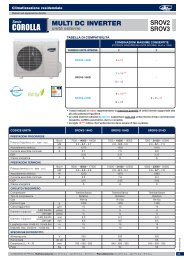
1X2 Multi DC Inverter<br />
UN’UNITÀ<br />
DUE UNITÀ<br />
2.6kW 2.6kW +2.6kW 3.6kW + 3.6kW<br />
3.6kW 2.6kW + 3.6kW<br />
1X3 Multi DC Inverter<br />
UN’UNITÀ DUE UNITÀ TRE UNITÀ<br />
2.6kW 2.6kW +2.6kW 3.6kW + 3.6kW 2.6kW +2.6kW+2.6kW<br />
3.6kW 2.6kW + 3.6kW 2.6kW +2.6kW+3.6kW<br />
1X4 Multi DC Inverter<br />
UN’UNITÀ DUE UNITÀ TRE UNITÀ QUATRO UNITÀ<br />
2.6kW 2.6kW +2.6kW 3.6kW + 3.6kW 2.6kW +2.6kW+2.6kW 2.6kW +3.6kW+3.6kW 2.6kW +2.6kW+2.6kW+2.6kW<br />
3.6kW 2.6kW + 3.6kW 3.6kW + 5.3kW 2.6kW +2.6kW+3.6kW 2.6kW +3.6kW+5.3kW 2.6kW +2.6kW+2.6kW+3.6kW<br />
5.3kW 2.6kW + 5.3kW 2.6kW +2.6kW+5.3kW 3.6kW +3.6kW+3.6kW<br />
20
IV. 5. INSTALLAZIONE DELL’UNITÀ INTERNA<br />
IV. 5.1 Installazione del corpo dell’unità<br />
• Usare delle barre d’acciaio per sostenere l’unità interna, Φ 10 mm e 4 bulloni per il fissaggio.<br />
• L’installazione a soffitto varia dal tipo di costruzione, consultare il costruttore per le procedure specifiche.<br />
1) La struttura del soffitto deve garantire una posizione piana dell’unità ed evitare eventuali vibrazioni.<br />
2) Tagliare il trave del tetto.<br />
3) Rinforzare il posto tagliato e consolidare il trave del tetto.<br />
• Terminata l’installazione del corpo principale, tirare il tubo e la linea elettrica nel soffitto.<br />
• Prima di procedere con l’installazione, determinare la direzione dei tubi da tirare. Particolarmente nel caso<br />
d’installazione a soffitto, posizionare i tubi refrigerante, tubi di scarico condensa i cavi di collegamento tra interna /<br />
esterna sui posti di collegamento prima di sospendere la macchina.<br />
• Installazione dei ganci appendente<br />
Costruzione di legno<br />
Mettere l’asse sopra la trave del tetto, quindi installare le barre di sostegno di sostegno.<br />
Legname sopra il trave<br />
Trave del soffitto<br />
Soffitto<br />
Bullone vite di sospensione<br />
Fig.5-1<br />
Nuovi mattoni calcestruzzi<br />
Intarsiare o includere i bulloni delle viti. (Riferirsi alla Fig.5-2)<br />
Inserzione lamierina Lato inserzione<br />
Fig.5-2<br />
Nuovi edifici e soffitti<br />
Usare vite fischer, mattoni forti di terracotta. (riferirsi alla Fig.5-3)<br />
Barra d’acciaio<br />
Bullone vite d’incastro<br />
Fig.5-3<br />
Struttura d’acciaio del trave del tetto<br />
Installare direttamente ed usare la barra di sostegno in acciaio. (riferirsi alla Fig.5-4)<br />
Bulloni vite appendente<br />
Bulloni di sostegno<br />
Barra in acciaio<br />
di sostegno<br />
Fig.5-4<br />
21
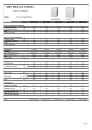
Posizione del foro a soffitto e dell’unità interna e dell’attacco vite<br />
Fig.5-4<br />
A<br />
B<br />
148<br />
B<br />
Air outlet sketch map<br />
268<br />
385<br />
220<br />
102<br />
C<br />
D<br />
Air outlet sketch map<br />
82<br />
Air inlet<br />
A<br />
100<br />
ø 100<br />
>250mm<br />
C<br />
>500m<br />
Fig.5-5<br />
MODELLI A B C D<br />
2600 W 915 870 715 870<br />
3600 W 915 870 715 870<br />
5300 W 1260 1224 1015 1215<br />
>500m<br />
Pannello d’ingresso aria<br />
Griglia ingresso aria<br />
Ingresso aria<br />
Griglia ingresso aria<br />
Ingresso aria<br />
Fig.5-6<br />
ATTENZIONE<br />
Tenere le alette della griglia in livello orizzontale (come da figura sopra Fig.5-6) altrimenti l’unità potrebbe emettere<br />
forti rumori.<br />
IV. 5.2 INSTALLAZIONE ACCESSIORI DEL CANALIZZATO<br />
IV. 5.2.1 INSTALLAZIONE DELLA PIASTRA DI FISSAGGIO<br />
Fissare la piastra di fissaggio con i bulloni forniti come accessori. (se usate altri bulloni, state attenti che la lunghezza<br />
sia appropriate e assicuratevi di non danneggiare l’unità.<br />
Bullone fissazione<br />
Fig.5-7<br />
IV. 5.2.2 INSTALLAZIONE DELLA PIASTRA DI FISSAGGIO<br />
Fissare il canalizzato sulla piastra di installazione con i ribattini come indicato nella figura sopra.<br />
Ribattino (per fissare<br />
il canalizzato)<br />
Unità interna<br />
Uscita aria<br />
Fig.5-8<br />
22
NOTE:<br />
Non lasciare che l’unità interna sostenga il peso del canalizzato. Per la manutenzione installare il canalizzato in un<br />
luogo facilmente accessibile. In caso di installazione in sale riunioni o posti simili, attrezzare l’unità di silenziatore.<br />
IV. 5.2.3 Accessori opzionali<br />
Nome Quantità Specifiche Funzione<br />
Piastra di fissaggio 8 Collegare il canalizzato<br />
Bulloni di fissaggio 8 ST3.9X10-F-H Fissare la piastra di fissaggio<br />
IV. 5.2.4 Installazione del tubo di scarico dell’unità interna<br />
1- Materiale isolante<br />
Tubazioni<br />
Materiale isolante<br />
PVC<br />
Polietilene - 6mm<br />
Nessun spazio<br />
Tubo PVC rigido<br />
Materiale isolamento<br />
termico<br />
Materiale isolamento<br />
termico<br />
Unità principale<br />
Sigillare il materiale<br />
d’isolamento termico<br />
Fig.5-9<br />
2. Drenaggio<br />
Fig.5-10<br />
2- Isolante termico<br />
Isolare termicamente il giunto fissando l’isolante fasciando le tubazioni.<br />
ATTENZIONE<br />
- Il tubo di scarico come le parti di connessione dell’unità interna devono essere isolate termicamente altrimenti si può<br />
formare condensa.<br />
- Fissare saldamente le tubazioni in modo da prevenire gocciolamenti.<br />
- Non imporre la pressione sulle parti di connessione dello scarico.<br />
- Il gradiente in discesa del tubo di scarico deve essere sopra 1/100, and e non piegare il tubo di scarico.<br />
- Tirare il tubo di drenaggio trasversalmente all’interno di 20m. Installare un sostenitore nel caso che il tubo di scarico<br />
è troppo lungo per prevenire la curvatura.<br />
- Riferirsi alla scheda di installazione delle tubazioni.<br />
1.5m~2m<br />
Dislivello circa 10cm<br />
Curva<br />
Materiale<br />
is olante<br />
Inclinazione in descesa<br />
inferiore di 1/100<br />
Forma S<br />
IV. 5.3. INSTALLAZIONE DELL’UNITÀ SOFFITTO-PAVIMENTO<br />
Inclinazione in des cesa<br />
inferiore di 1/10 0<br />
VP30<br />
Fig.5-11<br />
IV. 5.3.1 Installazione su muro dell’unità soffitto – pavimento<br />
23
D Gancio<br />
A C<br />
D. Attacco tubo<br />
refrigerante<br />
D. lato gas<br />
Attacco tubo scarico condensa<br />
D. Attacco tubo<br />
refrigerante<br />
E. Lato liquido<br />
(1) Si consiglia di usare un indicatore di livello per installare l’unità sul muro.<br />
(2) Mantenere l’unità perpendicolare al suolo.<br />
Fig.5-12<br />
Gancio<br />
Bullone dio fissaggio<br />
Rondella<br />
20mm<br />
D. Attacco tubo refrigerante<br />
(D. Lato gas)<br />
E. Attacco tubo refrigerante<br />
(E. Lato liquido)<br />
G<br />
H<br />
Bullone di montaggio<br />
Attacco scarico condensa<br />
Fig. 5-17<br />
ATTENTION: Le immagini indicate sopra sono soltanto un esempio illustrativo per i modelli 3600 – 5300 W e<br />
possono essere lievemente diverse dal condizionatore che avete acquistato (a seconda del modello).<br />
24
Dimensioni Soffitto – Pavimento<br />
Capacità (W)<br />
Dimensioni (mm)<br />
A B C D E F G H<br />
3600 W– 5300 W 990 660 206 505 506 907 200 203<br />
IV. 5.3.3 Installazione delle tubazioni di frigorifere<br />
Controllare il dislivello fra l'unità interna e l'unità esterna, la lunghezza del tubo refrigerante ed il numero delle<br />
piegature verificano le seguenti richieste:<br />
Unità interne che possono<br />
essere usate in combinazione<br />
Numero delle unità connesse<br />
Lunghezza totale (tutte le stanze)<br />
Lunghezza per un’unità interna<br />
Quando l’unità interna è installata<br />
Dislivello tra le unità interna ed sopra l’unità esterna (B)<br />
esterna<br />
Quando l’unità interna è installata<br />
sotto l’unità esterna (A)<br />
Dislivello tra unità interne<br />
IV. 5.3.4 Procedura di connessione dei tubi.<br />
1 - 4 unità<br />
Max. 60m<br />
Max. 15m<br />
Max. 10m<br />
Max. 10m<br />
Max. 10m<br />
- Assicurarsi che non vi sia sporcizia od acqua nelle tubazioni prima di provvedere a realizzare le connessioni.<br />
- L’installazione dei tubi di connessione deve essere effettuata prima del fissaggio delle unità interna ed<br />
esterna.<br />
! CAUTELE<br />
- Mantenere i tubi di connessione asciutti e non lasciate l’umidità penetrare dentro durante l’installazione.<br />
- Coprire completamente i tubi di connessione lato liquido e lato gas con dell’isolamento termico per evitare la<br />
formazione di condensa.<br />
• Realizzare un foro nella parete (adatto al formato del condotto della parete, 90mm in generale), regolata sui montaggi<br />
quali il condotto della parete e la sua copertura.<br />
• E’ possibile avvolgere i cavi di comunicazione attorno all’isolante delle tubazioni di refrigerante.<br />
• Passare il tubo di connessione legato tramite il condotto della parete dalla parte esterna. Fare attenzione alla<br />
posizione del tubo non danneggiare la tubazione.<br />
• Connettere i tubi<br />
• Evacuare l'aria con pompa a vuoto.<br />
• Aprire le valvole di arresto dell’unità esterna per connettere il tubo refrigerante con l’unità interna e esterna.<br />
• Controllare che non ci siano perdite controllando con dispositivo cercafughe o con acqua saponata.<br />
• Coprire la giunta tra tubazioni e l’unità interna con dell’isolante termico e bloccarlo con del nastro adesivo per<br />
garantire un corretto isolamento termico ed evitare così la formazioni di condensa.<br />
! CAUTELA<br />
Coprire le tubazione entrambi lato liquido e lato gas e le giunte tra tubazioni e le unità interna e esterna con<br />
dell’isolante termico per evitare la formazioni di condensa.<br />
IV. 5.3.5 Connessione del tubo di drenaggio<br />
■ Installazione del tubo di drenaggio dell’unità interna<br />
Si prega di usare materiale adesivo, si prega di coprirle con una guaina nella connessione del tubo PVC.<br />
25
! CAUTELA<br />
• Coprire il tubo di drenaggio e il tubo refrigerante dell’unità interna con dell’isolamento termico per evitare la<br />
formazione della rugiada.<br />
• Applicare un legante PVC al tubo di connessione, ed accertatevi che non vi siano perdite.<br />
• Si prega di non imporre pressione sulla parte di connessione delle tubazioni con l’unità interna.<br />
• La lunghezza del tubo di scarico condensa può raggiungere 20m, quando il tubo è lungo installate un<br />
sostegno per evirate che si incurvi.<br />
• Riferirsi alle figure qui sotto per l’installazione dei tubi.<br />
1.5m~2 m<br />
Dislivello circa 10cm<br />
Curva<br />
Materiale<br />
is olante<br />
Inclina z ione in de sc esa<br />
inferiore di 1/100<br />
Forma S<br />
Inclinazione in des cesa<br />
inferiore di 1/10 0<br />
VP30<br />
Fig. 5-18<br />
■ Teste di drenaggio<br />
• Verificare se il tubo di drenaggio non è ostruito.<br />
• Nei nuovi edifici il test di drenaggio dovrebbe essere realizzato prima della pavimentazione del soffitto.<br />
IV. 5.3.6 Cablaggio elettrico<br />
• Il cablaggio elettrico dell’apparecchio deve essere effettuato in concordanza con le normative nazionale.<br />
• II condizionatore deve essere collegato ad un circuito di alimentazione autonomo.<br />
• La messa a terra del gruppo di alimentazione del condizionatore e dell’unità interna ed esterna deve essere<br />
fatta correttamente.<br />
• Il lavoro di cablaggio deve essere fatto da persone qualificate rispettando gli schemi di cablaggio.<br />
! CAUTELA<br />
• Collegare un adeguato magnetotermico differenziale a protezione dei collegamenti e della macchina<br />
• Il cavo di alimentazione ed il cavo segnale devono essere installate separatamente per evitare i fenomeni di<br />
interferenza.<br />
• Collegare l’alimentazione solo dopo aver controllato con cura il cablaggio.<br />
NOTE:<br />
Note per EMC la direttiva 89/336/EEC. Per impedire la formazione di scintille della corrente durante l'avvio del<br />
compressore (processo tecnico), applicare le seguenti condizioni d'installazione.<br />
1. Il collegamento d’alimentazione al condizionatore deve essere fatto direttamente all’alimentazione principale. La<br />
linea elettrica deve essere a bassa impedenza, normalmente l’impedenza necessaria si raggiunga ad un punto di<br />
fusione 32A.<br />
2. Nessun’altra apparecchiatura deve essere collegata con questa linea elettrica.<br />
3. Accertarsi sulle restrizione che devono essere applicate all’uso d’altre apparecchiature come lavatrici,<br />
condizionatori o forni elettrici.<br />
4. Per maggiori dettagli sull’alimentazione del condizionatori riferirsi alla targa dell’apparecchiatura.<br />
5. Per qualsiasi domanda contattare il fornitore.<br />
5. Per qualsiasi domanda contattare il fornitore.<br />
IV. 6 INSTALLAZIONE DELL’UNITÀ ESTERNA<br />
IV. 6.1 Luogo di installazione<br />
■ L’unità esterna dove essere installata nei seguenti luoghi.<br />
• In un luogo dove c’è sufficiente spazio per l’installazione e la manutenzione, e dove il vento non può essere forte.<br />
• Luoghi con sufficiente ventilazione.<br />
• Il supporto può sostenere il peso dell’unità esterna e deve essere piano e regolare per evitare le vibrazioni<br />
aggiuntive.<br />
26
• Luoghi o collocazioni in cui l’aria espulsa dall’unità esterna possa recare danno ai vicini.<br />
• In un luogo dove le tubazioni ed i cavi possano essere installati facilmente.<br />
• Dove lo sbocco d’uscita aria non è ostruito.<br />
• Dove non vi possono essere perdite di gas infiammabile<br />
• La lunghezza delle tubazioni tra l’unità interna e l’unità esterna deve essere ammissibile.<br />
• Nei luoghi vicino alla costa dove il vento può essere forte, installare l’unità esterna contro il muro per garantire il<br />
regolare funzionamento. Usare un schermo se necessario (Fig.6-1)<br />
O<br />
Vento forte<br />
Fig.6-1<br />
• Evitare che l’unità sia sottoposta alla radiazione diretta od al calore di altre apparecchiature. Se non si può evitare,<br />
prevedere un riparo.<br />
• Evitare l’installazione in un luogo in cui l’acqua di scarico condensa durante il funzionamento di riscaldamento<br />
possa recare danno alle persone.<br />
• Evitare l’installazione in un luogo che sarà oggetto di neve, accumulo di foglie o altri detriti stagionale. Se<br />
inevitabile, prevedere un riparo.<br />
• Posizionare l’unità esterna in un luogo vicino all’unità interna.<br />
Se possibile, rimuovere gli ostacoli vicini all’unità per favorire la circolazione dell’aria.<br />
• La minima distanza tra l’unità esterna ed gli ostacoli descritte sopra non sono valide per locali a tenuta d’aria o<br />
locali chiusi. Lasciare liberi almeno 2 delle 3 direzioni (Fig. 6-2)<br />
X<br />
(Muro o ostacolo)<br />
c<br />
m<br />
Ingresso aria<br />
0<br />
3<br />
>3 0c m<br />
><br />
N<br />
Ingresso aria<br />
Canale di sostegno<br />
>60 cm<br />
P<br />
c<br />
m<br />
0 M<br />
Uscita aria<br />
2<br />
Fig. 6-2<br />
IV. 6.2 Installazione della pipetta di drenaggio dell’unità esterna<br />
Adattare la guarnizione alla pipette scarico condensa; inserire la pipette nel buco sul pannello base dell’unità esterna,<br />
ruotare di 90° per assicurare l’assemblaggio. Collegare la pipetta con un tubo nel caso in cui la condensa defluisca<br />
dall’unità esterna durante il funzionamento in riscaldamento. (Riferirsi alla Fig. 6-3)<br />
Guarnizione<br />
Pipetta di scarico<br />
Foro basamento<br />
dell'unità esterna<br />
Guarnizione<br />
Thebasepan<br />
Pipetta di scarico<br />
of outdoor unit Fig. 6-3<br />
27
IV 6.3 Tubazioni refrigerante<br />
1. Svasatura<br />
a). Tagliare correttamente un tubo.<br />
magro greggio ronzio<br />
90° A<br />
Fig. 6-4 Fig. 6-5<br />
b). Inserire il tubo nel dado e cartellare il tubo.<br />
Diametro esterno<br />
Tabella (mm)<br />
Max.<br />
Min.<br />
Ф 6.4 1.3 0.7<br />
Ф 9.5 1.6 1.0<br />
Ф 12.7 1.8 1.0<br />
2 Connettere l’unità interna prima e poi l’unità esterna.<br />
Piegare i tubi a mani se possibile, evitando di romperli.<br />
Piegare il tubo con il police<br />
Raggio-min 100 mm Fig. 6-6<br />
• L’angolo di curvatura non deve superare 90°.<br />
• Piegare se possibile, il tubo di connessione nella parte centrale; maggiore è il raggio di piegatura e meglio è.<br />
• Non piegare né tendere il tubo più di tre volte.<br />
• Lubrificare le superfici del tubo refrigerante e dei dadi di giunzione con olio e tiralo per 3~4 tondi con le mani prima<br />
di fissare i dadi.<br />
Fig. 6-7<br />
• Accertarsi d’utilizzare simultaneamente due chiavi per connettere o disconnettere i tubi.<br />
! CAUTELA<br />
Fig.6-8<br />
Coppia di torsione troppo grande danneggia la lisciatura della flangia e causerà perdita nel sistema. E’<br />
consigliabile riferirsi alla tabella sotto.<br />
Dopo la fine dei lavori di connessione, controllare se ci sono perdite del gas refrigerante.<br />
Diametro esterno Coppia di torzione NM (N.cm) Additional tightening torque (N.cm)<br />
Ф 6.4 1570 (160kgf.cm) 1960 (200kgf.cm)<br />
Ф 9.5 2940 (300kgf.cm) 3430 (350kgf.cm)<br />
Ф 12.7 3500 (400kgf.cm) 4410 (450kgf.cm)<br />
28
IV 6.4 Spurgo dell’aria con la pompa del vuoto<br />
Operazione valvola di presa<br />
a) Valvola di arresto<br />
1. Rimuovere il cappuccio della valvole di arresto usando chiave esagonale<br />
2. Una coppia di torsione eccessiva può romper il corpo della valvola di arresto.<br />
3. Accertarsi di fissare saldamente il cappuccino della valvola di arresto.<br />
b) Chiusura della valvola di arresto<br />
1. Rimuovere il cappuccino della valvola e chiudere la valvola con una chiave esagonale.<br />
2. Stringere saldamente la valvola una chiave regolabile.<br />
Accertarsi che il cappuccio sia saldamente fissato. Per la coppia di torsione si veda tabella precedente.<br />
Usare un tubo flessibile di carica per la connessione della porta di servizio.<br />
! CAUTELA Dopo aver fissato il cappuccino, controllare se non ci sono perdite di refrigerante<br />
Porta di servizio<br />
Dado manut enzione<br />
Cappuccio<br />
Sigello<br />
Asta<br />
Foro esagonale<br />
Fig. 6-9<br />
• Utilizzare una pompa a vuoto<br />
Utilizzare una pompa a vuoto per fare il vuoto nelle tubazioni sia dal lato gas che dal lato liquido, preferibilmente in<br />
modo simultaneo.<br />
1. Allentare e rimuovere i dadi di servizio delle valvole di arresto A e B, e collegare il tubo flessibile di carica della<br />
manipola alla porta di servizio della valvola di arresto A. (Accertarsi che le valvole A e B soni entrambi chiuse)<br />
2. Connettere la giunta del tubo flessibile alla pompa a vuoto.<br />
3. Aprire completamente la leva Lo della manopola.<br />
4. Azionare la pompa di vuoto. All’inizio dello spurgo, allentare il dado di servizio della valvola di arresto B per<br />
controllare se l’aria penetra dentro (il suono della pompa cambia, e l’indicatore del decimetro “Compund meter”<br />
scende sotto zero). Dopodichè chiudere il dado di servizio.<br />
5. Quando l’evacuazione è conclusa, chiudere la manopola “Lo” della valvola manometro e arrestare la pompa a<br />
vuoto. Fare il vuoto per oltre 15 minuti, controllare se l’indicatore del tester ha raggiunto -76cmHg (-1X10 Pa).<br />
6. Rimuovere il cappuccio delle valvole di arresto A e B per aprire le valvole d’arresto A e B, quindi fissarle.<br />
7. Smontare il tubo flessibile di carica dalla porta di servizio della valvola di arresto A e fissare il dado.<br />
Unità esterna<br />
Unità interna<br />
A<br />
Lato gas C<br />
B<br />
Valvola di arresto<br />
Lato liquido<br />
Fig. 6-10<br />
IV. 6.5 Quantità refrigerante addizionale che deve essere caricata<br />
D<br />
29
Manometro<br />
-76 cmHg<br />
Bassapressione<br />
Tubo flessibile<br />
Alta pressione<br />
Tubo flessibile<br />
Pompaavuoto<br />
! CAUTELA<br />
Presa di pressione Fig.6-11<br />
La carica refrigerante si effettua solo dopo la realizzazione del cablaggio elettrico.<br />
La carica refrigerante potrebbe essere effettuata dopo la realizzazione del test di perdita e l’evacuazione dei<br />
tubi.<br />
Durante l’operazione di carica del gas refrigerante, si deve prestare attenzione per evitare il fenomeno di<br />
liquefazione del gas refrigerante perchè la massima carica refrigerante ammissibile non si raggiunge mai.<br />
Usare il refrigerante R410A per la carica addizionale per evitare il pericolo esplosione e incendi.<br />
Aprire lentamente il contenitore del gas refrigerante.<br />
Nell’operazione di carica refrigerante usare guanti e occhiali per proteggere gli occhi.<br />
■ L’unità esterna è caricata con il refrigerante R 410A, non tossico e non infiammabile. La carica addizionale deve<br />
essere calcolata in funzione del diametro e della lunghezza del tubo del lato liquido.<br />
Connective pipe length<br />
Nessuna quantità refrigerante addizionale R(g) quando L(m)<br />
è inferiore di 5m (un solo senso)<br />
Quantità refrigerante addizionale quando la lunghezza del<br />
tubo L(m) è superiore di 5m (un solo senso)<br />
IV. 7. SCHEMA ELETTRICO<br />
Cavo di connessione<br />
Carica refrigerante addizionale<br />
-----------<br />
(L-5m)X15g<br />
10 mm 40 mm<br />
Morsettiera unità esterna<br />
L<br />
N<br />
Messa<br />
a terra<br />
Grounding<br />
Cablaggio<br />
Unità A<br />
Unità B Unità C Unità D<br />
Cavo di connessione<br />
Tra unità interna/esterna<br />
Unità interna A<br />
Cavo di connessione<br />
Tra unità interna/esterna<br />
Cavo di connessione<br />
Tra unità interna/esterna<br />
Cavo di connessione<br />
Tra unità interna/esterna<br />
Unità interna B Unità interna C Unità interna D<br />
Dual<br />
Trial<br />
Quadri<br />
1. Rimuovere il coperchio dei componenti elettrici dell’unità esterna.<br />
30
2. Isolare i cavi conduttori non utilizzati con un nastro PVC.<br />
! CAUTION<br />
Accertarsi di connettere i morsetti delle unità interne (A, B, C, D) ai terminali corrispondenti delle<br />
valvole Hi e Lo ed i terminali dei cavi segnali (A, B, C, D) o i dell’unità esterna rispettando lo schema<br />
di cablaggio per evitare il danneggiamento dei componiti elettrici.<br />
IV. 8. PROVA DI FUNZIONAMENTO<br />
• Il test deve essere eseguito solo dopo aver completato l’installazione.<br />
• Si prega di controllare i seguenti punti prima di eseguire il test.<br />
• Unità interna ed esterna installate correttamente.<br />
• Tubazioni e cavi elettrici collegati correttamente.<br />
• Test di pressione delle tubazioni eseguito.<br />
• Lo scarico condensa funziona regolarmente.<br />
• L’isolamento termico è stato eseguito correttamente.<br />
• La messa a terra è stata installata correttamente.<br />
• La lunghezza delle tubazioni e la carica di refrigerante sono state controllate.<br />
• La tensione di alimentazione corrisponde a quella di progetto per il condizionatore.<br />
• Ingresso ed uscita dell’aria delle unità interne ed esterne non sono ostruite.<br />
• Le valvole lato gas e lato liquido sono aperte.<br />
• Il condizionatore è stato pre-riscaldato dando tensione.<br />
4. Test operation<br />
■ Impostare con il telecomando il condizionatore in modalità raffreddamento, e controllare i seguenti punti come<br />
indicato nella parte d’uso di questo manuale. Sei si verifica qualche malfunzionamento, risolverlo servendosi delle<br />
indicazioni del capitolo “ANOMALIE” di questo manuale.<br />
• 1) Unità interna<br />
a. Verificare se accensione e spegnimento dal telecomando avvengono correttamente.<br />
b. Verificare se i tasti del controllo remoto sono tutti operativi.<br />
c. Verificare se i deflettori od alette si muovono regolarmente.<br />
d. Verificare se la temperatura interna è regolata correttamente.<br />
e. Verificare se gli indicatori sul ricevitore funzionano.<br />
f. Verificare se il tasto manuale funziona correttamente.<br />
g. Verificare se lo scarico condensa avviene con regolarità.<br />
h) Verificare se ci sono vibrazione o rumori strani durante l’operazione.<br />
j. Verificare se la capacità di riscaldamento è adeguata.<br />
• 2) Unità esterna<br />
a) Verificare se la presenza di eventuali rumori o vibrazioni fuori norma.<br />
b) h. Verificare se ci sono perdite di gas refrigerante.<br />
! CAUTELA<br />
La funzione di protezione del condizionatore impedisce l’accensione immediata di nuovo dopo averlo spento. Il<br />
condizionatore all’intervento della protezione potrà essere riavviato dopo circa 3 minuti dal suo spegnimento.<br />
31
32<br />
ENGLISH
INDEX<br />
I. DESCRIPTION<br />
II. IMPORTANT SAFETY INFORMATION<br />
III. OPERATION PART<br />
III. 1 CONTROLS SUPPLIED AS STANDARD................................................................ 37<br />
III.2. PARTS NAMES OF THE UNIT................................................................................ 43<br />
III.3. AIR CONDITIONER OPERATIONS AND PERFORMANCE ................................... 43<br />
III.4. HINTS FOR ECONOMICAL OPERATION............................................................... 43<br />
III.5. ADJUSTING AIR FLOW DIRECTION...................................................................... 44<br />
III.6. CLEAN THE AIR FILTER ........................................................................................ 44<br />
III.7. FOLLOWING SYMPTOMS ARE NOT AIR CONDITIONER TROUBLES................ 45<br />
III.9. TROUBLESHOOTING............................................................................................. 47<br />
IV. INSTALLATION PART<br />
IV.1. INSTALLATION PRECAUTION............................................................................... 48<br />
IV.2. INSTALLATION INFORMATION ............................................................................. 48<br />
IV.3. ACCESSORIES....................................................................................................... 48<br />
IV.4. COMBINATION RULES .......................................................................................... 49<br />
IV.5. INDOOR UNIT INSTALLATION .............................................................................. 50<br />
IV.6. OUTDOOR UNIT INSTALLATION .......................................................................... 56<br />
IV.7. WIRING DIAGRAMS ............................................................................................... 59<br />
IV.8. TEST OPERATION ................................................................................................. 60<br />
33
II. DESCRIPTION<br />
INDOOR UNIT<br />
Air inlet<br />
2<br />
1<br />
3<br />
2<br />
Air outlet<br />
Air inlet<br />
3<br />
Air outlet<br />
1<br />
Air outlet<br />
4<br />
3<br />
5<br />
4<br />
3<br />
5<br />
8<br />
6<br />
8<br />
6<br />
9<br />
7<br />
OUTDOOR UNIT<br />
9<br />
7<br />
INDOOR UNIT<br />
1 Air flow louver (at air outlet)<br />
2 Air inlet (with air filter in it)<br />
3 Installation part<br />
4 Remote controller<br />
5 Display panel<br />
6 Drain pipe<br />
OUTDOOR UNIT<br />
7<br />
8<br />
9<br />
Connecting pipe<br />
Air inlet<br />
Air outlet<br />
NOTE: All the pictures in this manual are for explanation purpose only. They may be slightly different from the air<br />
conditioner you purchased (depending on model). The actual shape shall prevail.<br />
34
II. IMPORTANT SAFETY INFORMATION<br />
To prevent injury to the user or other people and property damage, the following instructions must be followed.<br />
Incorrect operation due to ignoring of instructions may cause harm or damage.<br />
The important safety information is listed which must be read carefully.<br />
! WARNING<br />
The air conditioner must be installed by qualified persons<br />
Ask your dealer for installation of the air conditioner.<br />
Incomplete installation performed by yourself may result in a water leakage, electric shock, and fire.<br />
Ask your dealer for improvement, repair, and maintenance.<br />
Incomplete improvement, repair, and maintenance may result in a water leakage, electric shock, and fire.<br />
In order to avoid electric shock, fire or injury, or if you detect any abnormality such as smell of fire, turn off the power<br />
supply and call your dealer for instructions.<br />
Never let the indoor unit or the remote controller get wet.<br />
It may cause an electric shock or a fire.<br />
It is not good for your health to expose your body to the air flow for a long time.<br />
Never use a flammable spray such as hair spray, lacquer or paint near the unit.<br />
It may cause a fire.<br />
Do not insert fingers, rods or other objects into the air inlet or outlet.<br />
When the fan is rotating at high speed, it will cause injury.<br />
! DANGER<br />
Do not attempt to service the unit yourself. This unit has no user serviceable components opening and removing the cover will<br />
expose you to dangerous voltage. Turning off the power supply will not prevent potential electric shock.<br />
! DANGER<br />
Never put hands or objects into the air outlet of indoor and outdoor units. This unit contain a fan running at high speed. Contact<br />
with the moving fan will cause serious injury.<br />
! DANGER<br />
To avoid the risk of serious electrical shock, never sprinkle or spill water or liquid on the unit.<br />
! DANGER<br />
Ventilate the room occasionally while the air conditioner is in use, especially if there is also a gas appliance in use in this room.<br />
Failure to follow these directions may result in a loss of oxygen in the room.<br />
! WARNING<br />
To prevent electric shock, turn off the power or disconnect the power supply plug before beginning any cleaning or other routine<br />
maintenance. Follow the directions for cleaning in the owner's manual.<br />
! WARNING<br />
Do not use liquid cleaners or aerosol cleaners. Use a soft and dry cloth for cleaning the unit. To avoid electric shock, never<br />
attempt to clean the unit by sprinkling water on it.<br />
! CAUTION<br />
Do not use caustic household dry cleaners in the unit. Drain cleaners can quickly destroy the unit components (drain pan and<br />
heat-exchanger coil etc.).<br />
NOTE<br />
For proper performance, operate the unit under the usable operating temperature and humidity conditions indicated in the user’s<br />
part of this manual. If the unit is operated beyond these condition, it may cause malfunctions of the unit or dew dripping from the<br />
unit.<br />
Maintain room temperature at a comfortable level.<br />
Clean air filter<br />
A clogged air filter reduce cooling efficiency. Clean it once two weeks.<br />
Never open doors and windows more often than necessary<br />
To keep cool or warm air in the room, never open doors and windows more often than necessary.<br />
Windows curtains<br />
In cooling, close the curtain to avoid direct sunlight.<br />
Get uniform circulation of room air<br />
Adjust airflow direction for ever circulation of room air.<br />
35
! WARNING<br />
Be sure only trained and qualified service personnel to install, repair or service the equipment.<br />
Improper installation, repair, and maintenance may result in electric shocks, short-circuit, leaks, fire or other damage to the<br />
equipment.<br />
Install according to this installation instructions strictly.<br />
If installation is defective, it will cause water leakage, electrical shock fire.<br />
Install at a strong and firm location which is able to withstand the set' s weight.<br />
If the strength is not enough or installation is not properly done, the set will drop to cause injury.<br />
For electrical work, follow the local national wiring standard, regulation and this installation instructions. An<br />
independent circuit and single outlet must be used.<br />
If electrical circuit capacity is not enough or defect in electrical work, it will cause electrical shock fire.<br />
Use the specified cable and connect tightly and clamp the cable so that no external force will be acted on the terminal.<br />
If connection or fixing is not perfect, it will cause heat-up or fire at the connection.<br />
After completing the installation work, check that the refrigerant does not leak.<br />
Toxic gas may be produced if the refrigerant leaks into the room and comes into contact with a source of fire, such as a fan heater, stove or<br />
cooker.<br />
Use the attached accessories parts and specified parts for installation.<br />
otherwise, it will cause the set to fall, water leakage, electrical shock fire.<br />
Wiring routing must be properly arranged so that control board cover is fixed properly.<br />
If control board cover is not fixed perfectly, it will cause heat-up at connection point of terminal, fire or electrical shock.<br />
! CAUTION<br />
Don't install the air conditioner in the following locations:<br />
■ There is petrolatum existing.<br />
■ There is salty air surrounding (near the coast).<br />
■ There is caustic gas (the sulphide, for example) existing in the air (near a hot spring).<br />
■ The Volt vibrates violently (in the factories).<br />
■ In buses or cabinets.<br />
■ In kitchen where it is full of oil gas.<br />
■ There is strong electromagnetic wave existing.<br />
■ There are inflammable materials or gas.<br />
■ Other special conditions.<br />
36
III. OPERATION PART<br />
III. 1 CONTROLS SUPPLIED AS STANDARD<br />
• Remote control R51 with batteries.<br />
SET TEMPERATUR (°C)<br />
AU TO<br />
COOL<br />
DRY<br />
HEAT<br />
FAN<br />
HIGH<br />
MED<br />
LOW<br />
TEMP.<br />
MODE<br />
ON/OFF FAN SPEED<br />
SWING ECONOMIC TIMER ON<br />
TIMER OFF<br />
RESETLOCK<br />
AIR DIRECTION<br />
POWERFUL<br />
III. 1.1 INSTRUCTIONS FOR USE<br />
The following operations can be carried out using the remote control:<br />
• Switching the unit on/off.<br />
• Selection of the three fan speeds.<br />
• Adjusting the thermostat and maintaining the desired ambient temperature.<br />
• Switching between the cooling/heating operating cycle.<br />
The unit panel houses a number of indicators which provide information on the unit status or alarm signals. If the<br />
remote control is temporarily unavailable, it can be used to operate the unit in manual mode using the MANUAL key.<br />
III. 1.2 REMOTE CONTROL R51<br />
The remote control can be used to set and display all the unit operating parameters, facilitating the all programming<br />
operations. The remote control is powered by two 1.5 V AAA R03 batteries.<br />
IMPORTANT!<br />
It is advisable to test the remote control in order to establish its reception zone.<br />
37
III. 1.2.1 Description of the remote control and relative functions<br />
1<br />
2<br />
3<br />
4<br />
5<br />
6<br />
7<br />
SET TEMPERATURE (°C)<br />
AUTO<br />
COOL<br />
DRY<br />
HEAT<br />
TEMP.<br />
FAN<br />
HIGH<br />
MED<br />
LOW<br />
MODE ON/OFF FAN SPEED<br />
SWING<br />
AIR DIRECTION<br />
ECONOMIC TIMER ON<br />
RESET LOCK<br />
TIMER OFF<br />
POWERFUL<br />
3<br />
8<br />
9<br />
10<br />
11<br />
10<br />
12<br />
13<br />
(1) Transmits the infrared signals to the unit receiver.<br />
(2) Indicates the unit status and operating modes.<br />
(3) These keys make it possible to set the desired ambient temperature.<br />
▲the requested temperature is increased up to 30 °C ▼ the requested<br />
temperature is decreased down to 17 °C. Every time the key is pressed<br />
the temperature is changes with 1°C.<br />
(4) Makes it possible to select the desired operating mode (AUTO, COOL,<br />
DRY, HEAT, FAN).<br />
(5) This key enables the louver to swing vertically (horizontally).<br />
(6) Press this button to reset the remote control settings.<br />
(7) Makes it possible to set the louver angle.<br />
(8) Makes it possible to switch the unit on and off. Press the key once to<br />
switch it on, press it again to switch it off.<br />
(9) Press this key to select the fan speed. When you select AUTO, the fan<br />
speed is automatically regulated on the basis of the ambient temperature.<br />
It is also possible to select the fan speed manually, choosing between 3<br />
settings: LOW, MED (MEDIUM); HIGH.<br />
(10) Press these keys to set the unit on/off timer.<br />
(11) This function is not available in the units.<br />
(12) Makes it possible to lock all the remote control functions.<br />
(13) Press this button on cooling/heating mode to go into powerful<br />
cooling(heating) operation. Press again to cancel it.<br />
III. 1.2.2 Description of the display<br />
1<br />
2<br />
4<br />
3<br />
2<br />
8<br />
5<br />
TIMERON OFF<br />
6,7<br />
1) Transmission indicator appears whenever a signal is transmitted to the internal unit.<br />
2) Operating mode display (MODE): Indicates the selected mode.<br />
3) ON/OFF display: Indicates that the unit is in operation.<br />
4) Temperature display (TEMP): Indicates the set temperature (from 17 °C to 30 °C). When the FAN operating mode<br />
is selected, no temperature is displayed.<br />
5) Lock display: Indicates that the remote control is locked.<br />
6) Timer display (TIMER ON). If you press the TIMER ON key, the timer on time is displayed.<br />
7) Timer display (TIMER OFF). If you press the TIMER OFF key, the timer off time is displayed.<br />
8) Fan speed display (FAN): Indicates the selected fan speed. It may be displayed as AUTO or one of the three<br />
speeds: LOW, (MED) MEDIUM, HIGH.<br />
III. 1.2.3 Using the remote control<br />
The remote control uses two 1.5 V, R03 type AAA batteries (provided). To insert the batteries, remove the cover<br />
completely from the remote control by sliding it downwards. Insert the batteries in the relative housing, making sure<br />
38
you respect the polarities indicated. Replace the cover and select the desired functions. Follow the same steps when<br />
replacing flat batteries with new batteries. On average the batteries last for around one year.<br />
The remote control display is always on. Remove the batteries from the remote control if you expect not to use it for a<br />
long period of time. <strong>Point</strong> the remote control towards the unit receiver when setting the various functions. If the signals<br />
are received correctly, the unit will emit a "beep". The remote control is able to transmit up to a distance of around 11<br />
metres from the receiver. Do not expose the remote control to excessive damp, direct sunlight or other heat sources,<br />
and do not subject it to knocks. Protect the remote control from water and other liquids. If the unit's infrared receiver is<br />
exposed to direct sunlight or strong artificial light, or if a fluorescent lamp with electronic switch is placed nearby, the<br />
unit could be subject to operating anomalies or may not work at all. The use of other remote controls in the vicinity or<br />
in the same room as the unit could affect its operation. Do not point other remote control transmitters at the unit<br />
receiver.<br />
III. 1.3 SWITCHING THE UNIT ON AND OFF<br />
ON/OFF<br />
Press the ON/OFF key to switch the unit on or off.<br />
When switching from ON to OFF the operating mode is interrupted and current time delays are cancelled, while the<br />
appliance and fan operating modes and the set temperature value are memorised. When switching from OFF to ON,<br />
the machine automatically restores all the operating modes memorised before it was switched off.<br />
When the unit is on, the unit on symbol appears on the display.<br />
The presence of this symbol on the display indicates that the remote control is transmitting the settings to unit ▲.<br />
III. 1.4 SETTING THE OPERATING MODE<br />
By pressing the Mode key several times it is possible to change the unit operating mode. The selected operating<br />
mode symbol appears on the display.<br />
AUTO: automatic mode.<br />
COOL: cooling mode.<br />
DRY: dehumidification mode.<br />
HEAT: heating mode.<br />
FAN: fan only mode.<br />
When the automatic programme AUTO is selected, the unit may operate in COOLING or HEATING mode depending<br />
on the temperature difference in place between the ambient temperature and the temperature selected on the remote<br />
control. When the cooling programme COOL is selected, the unit operates with a free temperature setting, lowering<br />
the ambient temperature. When the dehumidification programme DRY is selected, the unit operates with a free<br />
temperature setting, progressively lowering the ambient temperature and humidity. When the dehumidification<br />
programme DRY is in operation, the FAN SPEED button cannot be used. When the heating programme HEAT is<br />
selected, the unit operates with a free temperature setting, raising the ambient temperature. When the fan programme<br />
FAN is selected, the unit operates without temperature settings, simply blowing air through the environment.<br />
IMPORTANT!<br />
- The unit fan stops when the set temperature is reached and is then automatically reactivated at minimum speed to<br />
prevent air stratification phenomena in the vicinity of the appliance.<br />
- When the COOL DRY mode is selected, the fan may not start up straight away because the ANTI-HEATING<br />
mode is present (see paragraph I.4.6.1). When the HEAT mode is selected, the fan may not start up straight away<br />
because the ANTI-COOLING mode is present (see paragraph I.4.6.2).<br />
39
III. 1.5 ECONOMY MODE<br />
ECONOMIC<br />
Use this function to go into saving-energy running.<br />
III. 1.6 SETTING THE DESIRED TEMPERATURE<br />
▲and▼ by pressing these keys in the AUTO, COOL, DRY and HEAT modes, it is possible to increase or reduce the<br />
desired temperature between 17°C and 30°C. The display shows the selected temperature.<br />
III. 1.7 SETTING THE LOUVER<br />
In order to obtain optimal air distribution, adjust the motorised louver, making sure that the air flow is not directly<br />
pointed at anyone. For the motorised louver, proceed as follows:<br />
AIR<br />
DIRECTION<br />
By pressing the AIR DIRECTION key several times it is possible to modify the position of the deflector.<br />
SWING<br />
By pressing the SWING key it is possible to activate continuous louver swing mode.<br />
DANGER!<br />
Moving the motorised louver manually when the unit is on could cause operating problems or damage the<br />
adjustment system.<br />
III. 1.8 SETTING THE FAN<br />
By pressing the FAN SPEED key several times it is possible to adjust the fan speed between the three available<br />
speeds, or to activate the AUTO mode. The operating mode appears on the display:<br />
AUTO: automatic speed operation<br />
LOW: minimum speed operation<br />
MED: medium speed operation<br />
HIGH: high speed operation<br />
III. 1.9 SETTING THE TIMER<br />
IMPORTANT!<br />
In order for the timer settings to have an effect, the remote control must ALWAYS be positioned near the unit (at a<br />
maximum distance of 11 metres) and be pointed towards the same.<br />
The TIMER function is not repetitive and must be set whenever you wish to use it. When the Timer ON-OFF function<br />
is selected, the unit may be switched on with a slight delay with respect to the programmed timer time. This should be<br />
considered completely normal and does not mean that the unit is not operating correctly.<br />
TIMER ON and TIMER OFF: Pressing these keys makes it possible to programme the unit on and/or off time.<br />
▲and▼: Pressing this key makes it possible to modify the switch-on or switch-off time. Whenever the key is pressed,<br />
the time is put forward or back by 0.5h then after 10h the it will increase with 1h in each press.<br />
III. 1.10 KEYPAD LOCK<br />
By using a sharp object to press the LOCK key it is possible to prevent use of the remote control keypad<br />
completely, meaning that it can be protected from use by children etc. The display will show the symbol<br />
illustrated here. To remove the keypad lock, use a sharp object to press the LOCK key again.<br />
III. 1.11 RESETTING THE REMOTE CONTROL<br />
By using a sharp object to press the RESET key, it is possible to restore the factory settings to the remote<br />
control.<br />
40
III. 1.12 RAPID OPERATING GUIDE<br />
SET TEMPERATURE (°C)<br />
AUTO<br />
COOL<br />
DRY<br />
HEAT<br />
FAN<br />
HIGH<br />
MED<br />
LOW<br />
TEMP.<br />
2<br />
1<br />
5<br />
MODE ON/OFF FAN SPEED<br />
SWING<br />
ECONOMIC TIMER ON<br />
RESET LOCK<br />
TIMER OFF<br />
4<br />
3<br />
6<br />
AIR DIRECTION<br />
POWERFUL<br />
III. 1.12.1 AUTOMATIC MODE<br />
When the automatic programme AUTO is selected, the unit may operate in COOLING or HEATING mode depending<br />
on the temperature difference in place between the ambient temperature and the temperature selected on the remote<br />
control.<br />
The unit will operate in Condition<br />
Cooling TA - TS > 1 °C<br />
Fan -1 °C ≤ TA - TS ≤ 1 °C<br />
Heating TA - TS < -1 °C<br />
TA = ambient temperature, TS = selected temperature<br />
III. 1.12.2 COOLING MODE<br />
To set the cooling mode COOL, proceed as follows:<br />
• select COOL mode by pressing the MODE key (1);<br />
• adjust the desired temperature by pressing the TEMP keys (2). The display shows values from 17 °C to 30 °C;<br />
• adjust fan speed by pressing FAN SPEED key (3), choosing between AUTO and other speeds HIGH-MED-LOW;<br />
• point the remote control at the unit receiver and press the ON/OFF key ON/OFF (4);<br />
• adjust the air flow in keeping with requirements by using the SWING key (5) or AIR DIRECTION key (6). Once these<br />
adjustments have been made, they will be offered when the unit is switched back on. If received by the unit, every<br />
signal transmitted by the remote control is confirmed by a "beep”.<br />
III. 1.12.3 DEHUMIDIFICATION MODE<br />
To set the dehumidification mode DRY, proceed as follows:<br />
• select the dehumidification programme by pressing the MODE key (1);<br />
• adjust the desired temperature by pressing the TEMP keys (2). The display shows values from 17 °C to 30 °C;<br />
• point the remote control at the unit receiver and press the ON/OFF key ON/OFF (4);<br />
• adjust the air flow in keeping with requirements by using the SWING key (5) or AIR DIRECTION key (6); Once these<br />
adjustments have been made, they will be offered when the unit is switched back on. If received by the unit, every<br />
41
signal transmitted by the remote control is confirmed by a "beep”. When the dehumidification programme DRY is<br />
selected, the unit operates with a free temperature setting, progressively lowering the ambient temperature and<br />
humidity. When the dehumidification programme DRY is in operation, the FAN SPEED button cannot be used.<br />
III. 1.12.4 HEATING MODE<br />
To set the heating mode HEAT, proceed as follows:<br />
• select the heating programme by pressing the MODE key (1);<br />
• adjust the desired temperature by pressing the TEMP keys (2). The display shows values from 17 °C to 30 °C;<br />
• adjust fan speed by pressing FAN SPEED key (3), choosing between AUTO and other speeds HIGH-MED-LOW;<br />
• point the remote control at the unit receiver and press the ON/OFF key ON/OFF (4);<br />
• adjust the air flow in keeping with requirements by using the SWING key (5) or AIR DIRECTION key (6). Once these<br />
adjustments have been made, they will be offered when the unit is switched back on. If received by the unit, every<br />
signal transmitted by the remote control is confirmed by a "beep”.<br />
III.1.12.5 FAN MODE<br />
To set the fan mode FAN, proceed as follows:<br />
• select the fan mode by pressing the MODE key (1);<br />
• adjust fan speed by pressing FAN SPEED key (3), choosing between AUTO and other speeds HIGH-MED-LOW;<br />
• point the remote control at the unit receiver and press the ON/OFF key ON/OFF (4);<br />
• adjust the air flow in keeping with requirements by using the SWING key (5) or AIR DIRECTION key (6); Once these<br />
adjustments have been made, they will be offered when the unit is switched back on. If received by the unit, every<br />
signal transmitted by the remote control is confirmed by a "beep” sound.<br />
42
IV.2. PARTS NAMES OF THE UNIT<br />
The air conditioner consists of indoor unit, outdoor unit, connecting pipe and remote controller. (Refer to Fig.2-.1)<br />
■ Function indicators on indoor unit display panel<br />
OPERATION AUTO TIMER<br />
PRE.-DEF.<br />
Fig.2-1<br />
NOTE: All the pictures in this manual are for explanation purpose only. They may be slightly different from the air<br />
conditioner you purchased (depending on model). The actual shape shall prevail.<br />
• The OPERATION lamp flashes once per second when connecting power supply.<br />
• The operation lamp on the first operated unit flashes two times per second, the lamp on the second operated unit<br />
will be lit all the time.<br />
• The operation lamp will be off when the air conditioner switch off.<br />
• The timer lamp will be lit when on/off time has been set.<br />
• The DEF lamp will be lit while defrosting and cooling air controlling.<br />
• The DEF lamp will be off while the indoor fan operating (High, MED, Low, Slight)<br />
• The TIMER lamp and DEF lamp flash 5 times per second while the modes conflicting.<br />
The OPERATION lamp and DEF lamp flash 5 times per second while high cooling<br />
IV.3. AIR CONDITIONER OPERATIONS AND PERFORMANCE<br />
Use the system in the following temperature for safe and effective operation. The Max operation temperature for the<br />
air conditioner. (Cooling/Heating)<br />
Mode<br />
Temperature Outdoor temperature Room temperature<br />
Cooling operation 17 °C ~ 43 °C 17 °C ~ 30 °C<br />
Heating operating 17 °C ~ 21 °C 0 °C ~ 30 °C<br />
! CAUTION<br />
1. For proper performance, operate the unit under the usable operating temperature and humidity conditions<br />
indicated in this owner's manual. If the unit is operated beyond these condition, it may cause malfunctions of<br />
the unit or dew dripping from the unit<br />
2. The phenomenon is normal that the surface of air conditioning may condense water when the relative larger<br />
humidity in room, please close the door and window.<br />
3. Optimum performance will be achieved within these operating temperature range.<br />
■ Three-minute protection feature<br />
A protection feature prevents the air conditioner from being activated for approximately 3 minutes when it restarts<br />
immediately after operation.<br />
■ Power failure<br />
Power failure during operation will stop the unit completely.<br />
● The OPERATION lamp on the indoor unit will start flashing when power is restored.<br />
● To restart operation, push the ON/OFF button on the remote controller.<br />
● Lightning or a car wireless telephone operating nearby may cause the unit to malfunction.<br />
Disconnect the unit with the power and then connect the unit with the power again. Push the ON/OFF button on the<br />
remote controller to restart operation.<br />
IV.4. HINTS FOR ECONOMICAL OPERATION<br />
The following should be noticed to ensure an economical operation:<br />
43
■ Adjust the air flow direction properly to avoid winding toward your body.<br />
■ Adjust the room temperature properly to get a comfortable situation and to avoid super cooling and superheat.<br />
■ In cooling, close the curtains to avoid direct sunlight.<br />
■ To keep cool or warm air in the room, never open doors or windows more often than necessary.<br />
■ Set the timer for the desired operating time.<br />
■ Never put obstructions near the air outlet or the air inlet. Or it will cause lower efficiency, even a sudden stop.<br />
■ If you don't plan to use the unit for a long time, please disconnect power and remove the batteries from the remote<br />
controller. When the power switch is connected, some energy will be consumed, even if the air conditioner isn't in<br />
operation. So please disconnect the power to save energy. And please switch the power on 12 hours before you<br />
restart the unit to ensure a smooth operation.<br />
■ A clogged air filter will reduce cooling or heating efficiency, please clean it once two weeks.<br />
IV.5. ADJUSTING AIR FLOW DIRECTION<br />
Duct Type<br />
* Adjust the louver horizontally when cooling.<br />
* Adjust the louver down (vertically) when heating.<br />
Note:<br />
1 Adjust the horizontal louver down when the air flow is down.<br />
2 The slant angle of horizontal louver must be less than 40° otherwise the water drop<br />
will be caused.<br />
Adjust left and right.<br />
Note:<br />
When adjusting air flow left/right, turn the vertical louver to certain angles and the angle<br />
isn't too big otherwise the water drop will be caused<br />
Duct-Ceiling Type<br />
The following is how to adjust the airflow direction when the air outlet parts(sold<br />
separately) is used with the indoor unit.<br />
Cooling<br />
To effectively cool the whole room, plea-se adjust the louver horizontally.<br />
Heating<br />
To effectively heat the bottom of the room please set the louver downwards.<br />
Ceiling-Floor Type<br />
* Adjust the air direction up and down<br />
* Auto-swing:<br />
Press SWING button, the louver will swing up and down automatically.<br />
Manual Swing<br />
Adjust the louver to achieve better cooling/heating effects.<br />
When cooling<br />
Adjust the louver horizontally.<br />
When heating<br />
* Adjust the louver downwards (vertically).<br />
* Adjust the air flow direction left and right<br />
III. 6 CLEAN THE AIR FILTER<br />
< 40°<br />
Aletta verticale<br />
Vertical louver<br />
44
Vacuum cleaner or pure water may be used to clean the air filter. If the dust accumulation is too heavy, please use<br />
soft brush and mild detergent to clean it and dry out in cool place.<br />
The air-in side should face up when using vacuum cleaner. (Refer to Fig. 7-4) The air-in side should face down when<br />
using water. (Refer to Fig. 7-5)<br />
Fig. 7-4 Fig. 7-5<br />
- Set the air filter and the especial function filter as they were and close the front panel<br />
Operation without air filters may result in troubles as dust will accumulate inside the indoor unit.<br />
! CAUTION Do not dry out the air filter under direct sunshine or with fire.<br />
IV. 7. FOLLOWING SYMPTOMS ARE NOT AIR CONDITIONER TROUBLES<br />
Symptom 1: The system does not operate.<br />
■ The air conditioner does not start immediately after the ON/OFF button on the remote controller is pressed. If the<br />
operation lamp lights, the system is in normal condition. To prevent overloading of the compressor motor, the air<br />
conditioner starts 3 minutes after it is turned ON.<br />
■ If the operation lamp and the "PRE-DEF indicator light, it means you choose the heating mode. When just starting, if<br />
the compressor has not started, the indoor unit appears "anti cold wind" protection because of its over low outlet<br />
temperature.<br />
Symptom 2: Change into the fan mode during cooling mode<br />
■ In order to prevent the indoor evaporator frosting, the system will change into fan mode automatically, restore to the<br />
cooling mode after soon.<br />
■ When the room temperature drops to the set temperature, the compressor goes off and the indoor unit changes to<br />
fan mode; when the temperature rises up, the compressor starts again. It is the same in the heating mode.<br />
Symptom 3: White mist comes out of a unit<br />
Symptom 3.1: Indoor unit<br />
When humidity is high during cooling operation If the interior of an indoor unit is extremely contaminated, the<br />
temperature distribution inside a room becomes uneven. It is necessary to clean the interior of the indoor unit. Ask<br />
your dealer for details on cleaning the unit. This operation requires a qualified service person.<br />
Symptom 3.2: Indoor unit, outdoor unit<br />
■ When the system is changed over to heating operation after defrost operation moisture generated by defrost<br />
becomes steam and is exhausted.<br />
Symptom 4: Noise of air conditioners cooling<br />
Symptom 4.1: Indoor unit<br />
■ A continuous low "shah" sound is heard when the system is in cooling operation or at a stop. When the drain pump<br />
(optional accessories) is in operation, this noise is heard.<br />
■ A "pishi-pishi" squeaking sound is heard when the system stops after heating operation. Expansion and contraction<br />
of plastic parts caused by temperature change make this noise.<br />
45
Symptom 4.2: Indoor unit, outdoor unit<br />
■ A continuous low hissing sound is heard when the system is in operation. This is the sound of refrigerant gas<br />
flowing through both indoor and outdoor units.<br />
■ A hissing sound which is heard at the start or immediately after stopping operation or defrost operation. This is the<br />
noise of refrigerant caused by flow stop or flow change.<br />
Symptom 4.3: Outdoor unit<br />
■ When the tone of operating noise changes. This noise is caused by the change of frequency.<br />
Symptom 5: Dust comes out of the unit<br />
■ When the unit is used for the first time in a long time. This is because dust has gotten into the unit.<br />
Symptom 6: The units can give off odours<br />
The unit can absorb the smell of rooms, furniture, cigarettes, etc., and then emit it again.<br />
Symptom 7: The outdoor unit fan does not spin.<br />
■ During operation. The speed of the fan is controlled in order to optimize product operation.<br />
Symptom 8: Heating capacity.<br />
In the heating operation, heat is observed from outdoor and released into the room. That is so-called heat pump<br />
system.<br />
When the outdoor temperature is too low, heat absorbed from outdoor reduced and will result in reduced heating<br />
capacity (see the right picture). There is a big difference in temperature between indoor and outdoor, and this will<br />
increase the heating load. In this case, you are recommended to use another heating apparatus in combination with<br />
the air conditioner<br />
Heating capacity<br />
High<br />
Low<br />
High Low<br />
Outdoor temperature<br />
9. Operation mode selection<br />
While simultaneously operating both indoor units, the secondary unit can not be operated in a mode conflicting to that<br />
of the primary unit. The unit initially started should be considered with each other, the TIMER lamp and DEF lamp<br />
located on the display panel of the secondary unit will flash at a rate of 5 times per second. This can be rectified<br />
through changing the operable mode of the conflicting unit.<br />
Table of mode conflicting in operation:<br />
UNIT B<br />
COOL HEAT DEHUMIDIFY FAN AUTO<br />
UNIT A<br />
COOL ENABLE DISABLE ENABLE ENABLE<br />
HEAT DISABLE ENABLE DISABLE DISABLE<br />
DEHUMIDIFY ENABLE DISABLE ENABLE ENABLE<br />
FAN ENABLE DISABLE ENABLE ENABLE<br />
MANDATORY COOL<br />
RUN ON THE SAME MODE AS THE PRIMARY UNIT<br />
AUTO COOL ENABLE DISABLE ENABLE ENABLE<br />
AUTO HEAT DISABLE ENABLE DISABLE DISABLE<br />
AUTO FAN ENABLE DISABLE ENABLE ENABLE<br />
ONLY RUN ON THE<br />
SAME MODE AS THE<br />
PRIMARY UNIT<br />
46
IV.8. TROUBLESHOOTING<br />
If one of the following malfunctions occur, stop operation, shut off the power, and contact with the dealer.<br />
Indicator lamps flash rapidly (2 times per second), after your disconnecting and connecting the unit<br />
again, the situation is the same.<br />
Fuse or circuit breaker work frequently.<br />
TROUBLES<br />
Foreign matter or matter has fallen into the unit.<br />
Remote controller is disabled or the switch is out of order.<br />
Any other unusual condition is observed.<br />
In any of the following conditions occur, check your unit and resolve corresponding problems referring to given<br />
remediation. If the trouble can’t settled contact the dealer.<br />
Trouble Cause Solutions<br />
Power failure.<br />
Wait for the comeback of power<br />
Power switch is open.<br />
Switch on the power<br />
Unit does not start<br />
Fuse of power switch may have blown. Replace the fuse<br />
Batteries in remote controller are exhausted. Replace the batteries<br />
The time is not start-up time you have set. Wait for cancel the time set.<br />
Temperature is not set correctly.<br />
Set the temperature properly. Please<br />
refer to “operation instructions”<br />
Air flowing normally with low<br />
Air filter is blocked with dust or dirtiness. Clean the air filter<br />
cooling (heating) effect<br />
Inlet/outlet of indoor/outdoor units are blocked. Clear all blockages<br />
Door or window is opened<br />
Close door and window<br />
Inlet/outlet of indoor/outdoor units are blocked. Clear door and window.<br />
Air flowing normally without<br />
Be in 3 minutes protection of compressor Wait<br />
cooling (heating) effect<br />
Temperature is not set correctly.<br />
Set the temperature properly.<br />
47
IV. INSTALLATION PART<br />
IV.1 INSTALLATION PRECAUTION<br />
■ Be sure to be in conformity with the local, national and international laws and regulations.<br />
■ Read "PRECAUTIONS" carefully before installation.<br />
■ The following pre<strong>caution</strong>s include important safety items. Observe them and never forget.<br />
■ Keep this manual in a handy place for future reference.<br />
! WARNING Failure to observe a warning may result in death.<br />
! CAUTION Failure to observe a <strong>caution</strong> may result in injury or damage to the equipment.<br />
After completing the installation, make sure that the unit operates properly during the start-up operation. Please<br />
instruct the customer on how to operate the unit and keep it maintained. Also, inform customers that they should store<br />
this installation manual along with the owner's manual for future reference.<br />
IV.2. INSTALLATION INFORMATION<br />
■ To install properly, please read this "installation manual" at first.<br />
■ The air conditioner must be installed by qualified persons.<br />
■ When installing the indoor unit or its tubing, please follow this manual as strictly as possible.<br />
■ If the air conditioner is installed on a metal part of the building, it must be electrically insulated according to the<br />
relevant standards to electrical appliances.<br />
■ When all the installation work is finished, please turn on the power only after a thorough check.<br />
■ Regret for no further announcement if there is any change of this manual caused by product improvement.<br />
- INSTALLATION ORDER<br />
■ Select the location;<br />
■ Install the indoor unit;<br />
■ Install the outdoor unit;<br />
■ Install the connecting pipe;<br />
■ Connect the drain pipe;<br />
■ Wiring;<br />
■ Test operation.<br />
IV.3. ACCESSORIES<br />
Please check whether the following fittings are of full scope. If there are some spare fittings, please restore them<br />
carefully.<br />
- Duct type<br />
Installation fittings<br />
NAME SHAPE QUANTITY<br />
1. Hook 2<br />
2 Hanging arm 2<br />
3. Remote controller 1<br />
Remote controller<br />
and its holder<br />
4. Holder 1<br />
5. Mounting screw (ST2.9×10-C-H) 2<br />
6. Alkaline dry batteries (AM4) 2<br />
Others 7. User’s and Installer’s manual ---------- 1<br />
48
AU TO<br />
COO L<br />
DRY<br />
HE AT<br />
FAN<br />
HIGH<br />
MED<br />
LOW<br />
MODE ON/OFF FAN SPEED<br />
AIR DIRECTION<br />
POWERFUL<br />
- Floor and Ceiling type<br />
No Name Qty. Outline Function<br />
1 1. Insulation pipe 2 Pipe joint heat insulation<br />
2 2. Remote controller 1 --------- Remote control air conditioner<br />
3 3. Big washer 8 --------- Overhang indoor unit<br />
4 4. Constriction bandage 10 --------- Binding insulation pipe<br />
5 5. Water outlet joint (for cool/heat type only) 1 --------- Outdoor unit drainage<br />
6 Gasket (for cool/heat type only) 1 --------- Outdoor unit drainage<br />
7 Copper nut 2 --------- Connecting pipe<br />
8 Drain hose 1 --------- Indoor unit drainage<br />
9 7# Alkaline battery 1 --------- ---------------------------<br />
10 Remote signal receiver subassembly 1 --------- ---------------------------<br />
11 Outdoor/indoor unit signal wire 1 --------- ---------------------------<br />
Cautions on remote controller installation:<br />
■ Never throw or beat the controller.<br />
■ Before installation, operate the remote controller to determine its location in a reception range.<br />
■ Keep the remote controller at least 1m apart from the nearest TV set or stereo equipment. (it is necessary to prevent<br />
image disturbances or noise interferences.)<br />
■ Do not install the remote controller in a place exposed to direct sunlight or close to a heating source, such as a<br />
stove.<br />
■ Note that the positive and negative poles are right positions when loading batteries.<br />
Mounting screw B<br />
ST2.9x10-C-H<br />
SET TEMPERATURE O C)<br />
TEMP.<br />
SWING ECONOMIC TIMER ON<br />
RESETLOCKTIMER OFF<br />
Remote controller<br />
holder<br />
Remote<br />
controller<br />
Fig.3-1<br />
IV. 4 COMBINATION RULES<br />
1X2 Multi DC Inverter<br />
ONE UNIT<br />
TWO INDOOR UNITS<br />
2.6kW 2.6kW +2.6kW 3.6kW + 3.6kW<br />
3.6kW 2.6kW + 3.6kW<br />
1X3 Multi DC Inverter<br />
ONE UNIT TWO INDOOR UNITS THREE INDOOR UNITS<br />
2.6kW 2.6kW +2.6kW 3.6kW + 3.6kW 2.6kW +2.6kW+2.6kW<br />
3.6kW 2.6kW + 3.6kW 2.6kW +2.6kW+3.6kW<br />
1X4 Multi DC Inverter<br />
ONE UNIT TWO INDOOR UNITS THREE INDOOR UNITS FOUR INDOOR UNITS<br />
2.6kW 2.6kW +2.6kW 3.6kW + 3.6kW 2.6kW +2.6kW+2.6kW 2.6kW +3.6kW+3.6kW 2.6kW +2.6kW+2.6kW+2.6kW<br />
3.6kW 2.6kW + 3.6kW 3.6kW + 5.3kW 2.6kW +2.6kW+3.6kW 2.6kW +3.6kW+5.3kW 2.6kW +2.6kW+2.6kW+3.6kW<br />
5.3kW 2.6kW + 5.3kW 2.6kW +2.6kW+5.3kW 3.6kW +3.6kW+3.6kW<br />
49
IV. 5. INDOOR UNIT INSTALLATION<br />
IV. 5.1 Install the main body<br />
• Installing φ10 hanging screw bolts. (4 bolts)<br />
• Please refer to the following figure for the distance measurement between the screw bolts.<br />
• Please install with φ10 hanging screw bolts.<br />
• The handling to the ceiling varies from the constructions, consult the construction personnels for the specific<br />
procedures.<br />
1. The size of the ceiling to be handled to keep the ceiling flat. Consolidate the roof beam for possible vibration.<br />
2. Cut off the roof beam.<br />
3. Strengthen the place cut off, and consolidate the roof beam.<br />
• Carry out the pipe and line operation in the ceiling after finishing the installation of the main body. While<br />
choosing where to start the operation, determine the direction of the pipes to be drawn out. Especially in case<br />
there is a ceiling, position the refrigerant pipes, drain pipes, indoor & outdoor lines to the connection places<br />
before hanging up the machine.<br />
• The installation of hanging screw bolts.<br />
Wooden construction<br />
Put the square timber transversely over the roof beam, then install the hanging screw bolts. (Refer to Fig. 5-1)<br />
Timber over the beam<br />
Roof beam<br />
Ceiling<br />
Hanging screw bolts<br />
Fig. 5-1<br />
New concrete bricks<br />
Inlaying or embedding the screw bolts. (Refer to Fig. 5-2)<br />
(Blade shape insertion)<br />
(Slide insertion)<br />
Fig. 5-2<br />
For Original concrete bricks<br />
Use embedding screw bold, crock and stick harness. (Refer to Fig. 5-3)<br />
Steel bar<br />
Embedding screw bolt<br />
(Pipe hanging and embedding<br />
screw bolt)<br />
Steel roof beam structure<br />
Install and use directly the supporting angle steel. (Refer to Fig. 5-4)<br />
Hanging screw bolt<br />
Fig. 5-3<br />
Hanging bolts<br />
Supporting<br />
angle steel<br />
Fig. 5-4<br />
50
The position of hanging bolts (unit mm)<br />
Fig. 5-4<br />
A<br />
B<br />
148<br />
B<br />
Air outlet sketch map<br />
268<br />
385<br />
220<br />
102<br />
C<br />
D<br />
Air outlet sketch map<br />
82<br />
Air inlet<br />
A<br />
100<br />
ø 100<br />
>250mm<br />
C<br />
>500m<br />
Fig. 5-5<br />
MODELS A B C D<br />
2600 W 915 870 715 870<br />
3600 W 915 870 715 870<br />
5300 W 1260 1224 1015 1215<br />
>500m<br />
Air Inlet Panel of Air Return Box<br />
Air-in grille<br />
Air inlet<br />
Air-in grille<br />
Air inlet<br />
Fig. 5-6<br />
CAUTION<br />
Make the air inlet grille and air inlet direction in parallel. See Chart a Chart b is incorrect, which may cause loud noise.<br />
IV. 5.2 INSTRUCTIONS FOR DUCT INSTALLATION ACCESSORIES<br />
IV. 5.2.1 Fix installation board<br />
Fix the installation board on duct outlet with the bolts in accessories. (If the bolt is self-provided, the length of bolt<br />
should be appropriate and make sure not to damage the inside of unit. See the above picture.<br />
Fixation bolt<br />
IV. 5.2.2 Duct installation<br />
Fix the duct on installation board with rivet. See the right picture.<br />
Fig. 5-7<br />
Rivet (fix the duct)<br />
Indoor unit<br />
Air outlet Fig. 5-8<br />
NOTE:<br />
Do not let the indoor unit bear the weight of duct. For convenient maintenance, install the duct at the place where it is<br />
easy to do removing. In case doing installation in meeting room or such places, please equip the interior with liner and<br />
51
muffler. These accessories are optional. Please refer to House-hold Central Air Conditioner Installation Manual for<br />
other requirements.<br />
IV. 5.2.3 ACCESSORIES<br />
Name Qty. Outline/specification Function<br />
Duct installation board 8 Connecting duct<br />
Fixation bolt (fixing installation board) 8 ST3.9X10-F-H Fixing duct installation board<br />
IV. 5.2.4 Indoor Unit Drainpipe Installation<br />
1- Piping, insulation material<br />
Piping<br />
Insulation material<br />
Hard PVC pipe<br />
Cellular polyethylene, thicker than 6mm<br />
No spa ce<br />
Hard PVC pipe<br />
He at insula tion<br />
material<br />
Seal the<br />
insula tion ma terial<br />
He at insula tion<br />
material<br />
Main unit<br />
2- Drainage<br />
Fig. 5-9<br />
Fig. 5-10<br />
3- Heat insulation<br />
Please do heat insulation on piping joint.<br />
Bind the contact insulation part between the unit and installation location with bandage.<br />
CAUTION<br />
- The drain pipe as well as the connection part of indoor unit must be heat insulated, or condensate will occur.<br />
- Please connect the pipe with horny PVC bond and make sure there is no leakage.<br />
- Do not impose the pressure on connecting part of drainpipe.<br />
- The gradient downwards of drain pipe should be over 1/100, and do not bend the drain pipe.<br />
- Pull the drain pipe transversely within 20m. Please install a supporter in case the drainpipe is very long to prevent it<br />
from bending.<br />
- Refer to the chart on the right for the installation of pipes.<br />
1.5m~2 m<br />
Dislivello circa 10cm<br />
Curva<br />
Materiale<br />
is olante<br />
Inclina z ione in de sc esa<br />
inferiore di 1/100<br />
Forma S<br />
Inclinazione in des cesa<br />
inferiore di 1/10 0<br />
VP30<br />
Fig.5-11<br />
52
IV. 5.3 FLOOR-CEILING INSTALLATION<br />
IV. 5.3.1 FLOOR-CEILING WALL MOUNTING INSTALLATION<br />
D<br />
Hook<br />
A<br />
D. Connecting point of<br />
refrigerant pipe<br />
D. gas side<br />
Drain point<br />
D. Connecting point of<br />
refrigerant pipe<br />
E. liquide side<br />
Fig. 5-12<br />
1. Fix the hook with tapping screw onto the wall.(Refer to Fig. 5-13)<br />
Hook<br />
Tapping screw<br />
Washer<br />
2. Hang the indoor unit on the hook.<br />
IV. 5.3.2 Ceiling Installation<br />
F<br />
20mm<br />
D. Connecting point of<br />
refrigerant pipe<br />
(D.gas side)<br />
E. Connecting point of<br />
refrigerant pipe<br />
(E. Liquid side)<br />
G<br />
H<br />
Mounting bolt<br />
Drain point<br />
Fig. 5-17<br />
53
ATTENTION: The figures above are based on model with 3600-5300 W type as rated capacity, which may differ from<br />
the unit you purchased.<br />
Floor – ceiling dimensions<br />
Dimensioni (mm)<br />
Capacity (W)<br />
A B C D E F G H<br />
3600 W– 5300 W 990 660 206 505 506 907 200 203<br />
IV. 5.3.3 Install the connecting pipe<br />
Check whether the height drop between the indoor units and between indoor unit - outdoor unit, the length of<br />
refrigerant pipe meet the following requirements:<br />
Indoor units that can be used<br />
in combination<br />
Number of connected units 1-4 units<br />
Total length for all rooms<br />
Max. 60m<br />
Length for one indoor unit<br />
Max. 15m<br />
Difference in height between When above outdoor unit (B) Max. 10m<br />
indoor and outdoor units When below outdoor unit (A) Max. 10m<br />
Difference in height between indoor units<br />
Max. 10m<br />
IV. 5.3.4 The Procedure of connecting pipes<br />
! CAUTION<br />
Do not let air, dust, or other impurities fall in the pipe system during the time of installation.<br />
The connecting pipe should not be installed until the indoor and outdoor units have been fixed already.<br />
Keep the connecting pipe dry, and do not let moisture in during installation.<br />
Execute heat insulation work completely on both sides of the gas piping and the liquid piping. Otherwise, this<br />
can sometimes result in water leakage.<br />
• Drill a hole in the wall (suitable just for the size of the wall conduit), then set on the fittings such as the wall conduit<br />
and its cover.<br />
• Bind the connecting pipe and the cables together tightly with binding tapes.<br />
• Pass the bound connecting pipe through the wall conduct from outside. Be careful of the pipe allocation to do on<br />
damage to the tubing.<br />
• Connect the pipes. Refer to "How to connect the pipes" for details.<br />
• Expel the air with a vacuum pump. Refer to "How to expel the air with a vacuum pump" for details.<br />
• Open the stop values of the outdoor unit to make the refrigerant pipe connecting the indoor unit with the outdoor<br />
unit in fluent flow.<br />
• Check the leakage. Check all the joints with the leak detector or soap water.<br />
• Cover the joints of the connecting pipe with the soundproof / insulating sheath (fittings), and bind it well with the<br />
tapes to prevent leakage.<br />
! CAUTION<br />
Be sure to with insulating materials cover all the exposed parts of the flare pipe joints and refrigerant pipe on<br />
the liquid-side and the gas-side. Ensure that there is no gap between them.<br />
Incomplete insulation may cause water condensation.<br />
IV. 5.3.5. Connect the drain pipe<br />
■ Install the drainpipe of the indoor unit<br />
Please use sealing materials and pipe sheath (fitting) when connecting PVC pipes.<br />
54
! CAUTION<br />
• The drain pipe of indoor unit must be heat insulated, or it will condense dew, as well as the connections of the<br />
indoor unit.<br />
• Hard PVC binder must be used for pipe connection, and make sure there is no leakage.<br />
• With the connection part to the indoor unit, please be noted not to impose pressure on the side of indoor unit<br />
pipes.<br />
• When the declivity of the drain pipe downwards is over 1/100, there should not be any winding.<br />
• The total length of the drain pipe when pulled out transversely shall not exceed 20m, when the pipe is over<br />
long, a prop stand must be installed to prevent winding.<br />
• Refer to the figures on the right for the installation of the pipes.<br />
1.5m~2 m<br />
Dislivello circa 10cm<br />
Materiale<br />
is olante<br />
■ Drainage test<br />
Inclina z ione in de sc esa<br />
inferiore di 1/100<br />
• Check whether the drainpipe is unhindered.<br />
Curva<br />
Forma S<br />
Fig. 5-18<br />
• New built house should have this test done before paving the ceiling.<br />
IV. 5.3.6 Wiring<br />
Inclinazione in des cesa<br />
inferiore di 1/10 0<br />
• The appliance shall be installed in accordance with national wiring regulations.<br />
• The air conditioner should use separate power supply with rated voltage.<br />
• The external power supply to the air conditioner should have ground wiring, which is linked to the ground<br />
wiring of the indoor and outdoor unit.<br />
VP30<br />
! CAUTION<br />
• The wiring work should be done by qualified persons according to circuit drawing.<br />
• An all-pole disconnection device which has at least 3mm separation distance in all pole and a residual current<br />
device(RCD)with the rating of above 10mA shall be incorporated in the fixed wiring according to the national<br />
rule.<br />
• Be sure to locate the power wiring and the signal wring well to avoid cross-disturbance.<br />
• Do not turn on the power until you have checked carefully after wiring.<br />
NOTE: Remark per EMC Directive 89/336/EECFor to prevent flicker impressions during the start of the compressor<br />
(technical process), following installation conditions do apply.<br />
1. The power connection for the air conditioner has to be done at the main power distribution. The distribution has to<br />
be of a low impedance, normally the required impedance reaches at a 32A fusing point.<br />
2. No other equipment has to be connected with this power line.<br />
3. For detailed installation acceptance please refer to your power supplier, if restrictions do apply for products like<br />
washing machines, air conditioners or electrical ovens.<br />
4. For power details of the air conditioner refer to the rating plate of the product.<br />
5. For any question contact your local dealer.<br />
IV.6. OUTDOOR UNIT INSTALLATION<br />
IV.6.1 Installation place<br />
■ The outdoor unit should be installed in the location that meets the following requirements:<br />
• There is enough space for installation and maintenance.<br />
• The air outlet and the air inlet are not impeded, and can not be reached by strong wind.<br />
55
• It must be a dry and well ventilating place.<br />
• The support is flat and horizontal and can stand the weight of the outdoor unit. And will no additional noise or<br />
vibration.<br />
• Your neighbourhood will not feel uncomfortable with the noise or expelled air.<br />
• It is easy to install the connecting pipes or cables.<br />
• Determine the air outlet direction where the discharged air is not blocked.<br />
• There is no danger of fire due to leakage of inflammable gas.<br />
• The piping length between the outdoor unit and the indoor unit may not exceed the allowable piping length.<br />
• In the case that the installation place is exposed to strong wind such as a seaside, make sure the fan operating<br />
properly by putting the unit lengthwise along the wall or using a dust or shield. (Refer to Fig.6-1)<br />
O<br />
Strong wind<br />
Fig. 6-1<br />
• If possible, do not install the unit where it is exposed to direct sunlight. If necessary, install a blind that does not<br />
interfere with the air flow.<br />
• During the heating mode, the water drained off the outdoor unit. The condensate should be well drained away by<br />
the drain hole to an appropriate place, so as not to interfere other people.<br />
• Select the position where it will not be subject to snow drifts, accumulation of leaves or other seasonal debris. If<br />
unavoidable, please cover it with a shelter.<br />
• Locate the outdoor unit as close to the indoor unit as possible.<br />
• If possible, please remove the obstacles nearby to prevent the performance from being impeded by too little of air<br />
circulation. Refer to Fig. 6-2.<br />
Side air outlet outdoor unit<br />
X<br />
(Wall or obstacle)<br />
Air inlet<br />
>30cm<br />
N<br />
Air inlet<br />
>200cm<br />
M<br />
Air outlet<br />
>30cm<br />
Maintain channel<br />
>60cm<br />
P<br />
Fig. 6-2<br />
IV. 6.2 Install the drain joint of the outdoor unit<br />
Fit the seal into the drain joint, then insert the drain joint into the base pan hole of outdoor, rotate 90 to securely<br />
assemble them. Connect the drain joint with an extension drain hose (Locally purchased), in case of the condensate<br />
draining off the outdoor unit during the heating mode. (Refer to Fig.6-3)<br />
Seal<br />
Dra in joint<br />
The base pan hole<br />
of outdoor unit<br />
Sea l<br />
56<br />
Thebasepan<br />
of outdoor unit<br />
Drain<br />
joint
IV. 6.3 Refrigerant piping<br />
1 Flaring<br />
a) Cut a pipe with a pipe cutter<br />
Fig. 6-3<br />
Oblique Roughness Burr<br />
90° A<br />
Fig. 6-4 Fig. 6-4 Fig. Fig. 6-5 6-5<br />
b) Insert a flare nut into a pipe and flare the pipe.<br />
Outer diameter<br />
Table 1-5 A(mm)<br />
Max.<br />
Min.<br />
Ф 6.4 1.3 0.7<br />
Ф 9.5 1.6 1.0<br />
Ф 12.7 1.8 1.0<br />
2 Connect the indoor unit at first, then the outdoor unit.<br />
Bend the tubing in proper way. Do not harm to them.<br />
Bendthepipewiththumb<br />
min-radius 100mm<br />
Fig. 6-6<br />
• The bending angle should not exceed 90.<br />
• Do not bend the pipe more than three times.<br />
• When connecting the flare nut, coat the flare both inside and outside with either oil or ester oil and initially tighten by<br />
hand 3 or 4 turns before tightening firmly.<br />
Fig. 6-7<br />
• Be sure to use both a spanner and torque wrench together when connecting or disconnecting pipes to /from the unit.<br />
! CAUTION<br />
Fig. 6-8<br />
Too large torque will harm the bell mouthing and too small will cause leakage. Please determine the torque<br />
according to Table below.<br />
After the connecting work is finished, be sure to check that there is no gas leak.<br />
57
Outer diameter Tightening torque NM (N.cm) Additional tightening torque (N.cm)<br />
Ф 6.4 1570 (160kgf.cm) 1960 (200kgf.cm)<br />
Ф 9.5 2940 (300kgf.cm) 3430 (350kgf.cm)<br />
Ф 12.7 3500 (400kgf.cm) 4410 (450kgf.cm)<br />
IV. 6.4 How to expel the air with a vacuum pump<br />
Stop valve operation introduction<br />
a) Opening stop valve<br />
1. Remove the cap and turn the valve counter clock-wise with the hexagon wrench.<br />
2. Turn it until the shaft stops. Do not apply excessive force to the stop valve. Doing so may break the valve body, as<br />
the valve is not a backseat type. Always use the special tool.<br />
3. Make sure to tighten the cap securely.<br />
b) Closing stop valve<br />
1. Remove the cap and turn the valve clockwise with the hexagon wrench.<br />
2. Securely tighten the valve until the shaft contacts the main body seal.<br />
Make sure to tighten the cap securely. For the tightening torque, refer to the table above.<br />
Always use a charge hose for service port connection.<br />
! CAUTION After tightening the cap, check that no refrigerant leaks are present.<br />
service port<br />
maintenance nut<br />
cap<br />
seal<br />
shaft<br />
hexagon hole<br />
Fig. 6-9<br />
• Using the vacuum pump<br />
1. Loosen and remove the maintenance nuts of stop valves A and B, and connect the charge hose of the manifold<br />
valve to the service port of stop valve A. (Be sure that stop valves A and B are both closed)<br />
2. Connect the joint of the charge hose with the vacuum pump.<br />
3. Open the Lo-lever of the manifold value completely.<br />
4. Turn on the vacuum pump. At the beginning of pumping, loosen the maintenance nut of stop valve B a little to<br />
check whether the air comes in (the sound of the pump changes, and the indicator of compound meter turns below<br />
zero). Then fasten the maintenance nut.<br />
5. When the pumping has finished, close the Lo-lever of the manifold valve completely and turn off the vacuum pump.<br />
Make pumping for 15 minutes or more and check that the compound meter indicates -76cmHg (-1X10 Pa)<br />
6. Loosen and remove the cap of stop valves A and B to open stop valve A and B completely, then fasten the cap.<br />
7. Disassemble the charge hose from the service port of stop valve A, and fasten the nut.<br />
In doo r<br />
Outdoor<br />
unit<br />
unit A<br />
Gas side C<br />
Liq uid side<br />
D<br />
B<br />
Stop valve<br />
Fig. 6-10<br />
58
IV. 6.5 Additional Refrigerant Charge<br />
Manifold valve<br />
Multi-meter Pressure meter<br />
-76 cmHg<br />
Lo-lever<br />
Charge hos<br />
Hi-lever<br />
Charge hose<br />
Vacuum pump<br />
Lo-lever<br />
Fig. 6-11<br />
! CAUTION<br />
Refrigerant cannot be charged until field wiring has been completed.<br />
Refrigerant may only be charged after performing the leak test and the vacuum pumping.<br />
When charging a system, care shall be taken that its maximum permissible charge is never exceeded, in view<br />
of the danger of liquid hammer.<br />
Charging with an unsuitable substance may cause explosions and accidents, so always ensure that the<br />
appropriate refrigerant is charged.<br />
Refrigerant containers shall be opened slowly.<br />
Always use protective gloves and protect your eyes when charging refrigerant.<br />
■ The outdoor unit is factory charged with refrigerant R410A. Calculate the added refrigerant according to the<br />
diameter and the length of the liquid side pipe of the outdoor unit/indoor unit connection.<br />
Connective pipe length<br />
Additional refrigerant to be charged<br />
No added refrigerant when the length L(m) is less than 5m -----------<br />
Added refrigerant when the pipe length L(m) is over than 5m<br />
(L-5m)X15g<br />
IV. 7 WIRING DIAGRAMS<br />
■ Connect the connective cables to the terminals as identified with their respective matched numbers on the terminal<br />
block of indoor and outdoor units.<br />
■ Re-install the Indoor unit and outdoor unit<br />
Do not touch the capacitor even if you have disconnected the power for there is still high voltage power on it, or<br />
electric shock hazard may occur. For your safety, you should start repairing at least 5 minutes later after the<br />
power is disconnected.<br />
! CAUTION The power is supplied from the Outdoor Unit. The four Indoor Unit are connected with a signal wire<br />
with the Outdoor Unit. Please make sure that the signal wires or power cords are connected reliably<br />
and correctly, or the air conditioner could not run normally.<br />
59
Installing wiring chart<br />
Connection cable<br />
10 mm 40 mm<br />
Terminal block of outddoor unit<br />
L<br />
N<br />
Grounding<br />
Grounding<br />
Wiring<br />
Unit A<br />
Unit B Unit C Unit D<br />
Connective cable<br />
of indoor unit and<br />
outdoor unit<br />
Connective cable<br />
of indoor unit and<br />
outdoor unit<br />
Connective cable<br />
of indoor unit and<br />
outdoor unit<br />
Connective cable<br />
of indoor unit and<br />
outdoor unit<br />
Indoor unit A<br />
Indoor unit B Indoor unit C Indoor unit D<br />
One - two<br />
One - three<br />
One - four<br />
1. Remove the electric parts cover from the outdoor unit.<br />
2. Connect the connection cables to the terminals as identified with their respective matched numbers on the terminal<br />
block of indoor and outdoor units.<br />
3. Insulate unused cords (conductors) with PVC-tape. Process them so they do not touch any electrical or metal parts.<br />
Make sure to connect the indoor unit (A,B,C,D) to the Hi and Lo valve and terminals of signal wires (A,B,C,D)<br />
of outdoor unit as identified with their respective matched connection. Wrong wiring connections may cause<br />
! CAUTION<br />
some electrical parts to malfunction.<br />
IV. 8. TEST OPERATION<br />
• The test operation must be carried out after the entire installation has been completed.<br />
• Please confirm the following points before the test operation:<br />
• The indoor unit and outdoor unit are installed properly.<br />
• Tubing and wiring are correctly completed.<br />
• The refrigerant pipe system is leakage-checked.<br />
• The drainage is unimpeded.<br />
• The heating insulation works well.<br />
• The ground wiring is connected correctly.<br />
• The length of the tubing and the added stow capacity of the refrigerant have been recorded.<br />
• The power voltage fits the rated voltage of the air conditioner.<br />
• There is no obstacle at the outlet and inlet of the outdoor and indoor units.<br />
60
• The gas-side and liquid-side stop valves are both opened.<br />
• The air conditioner is pre-heated by turning on the power.<br />
4. Test operation<br />
■ Set the air conditioner under the mode of "COOLING" with the remote controller, and check the following points. If<br />
there is any malfunction, please resolve it according to the chapter "Troubleshooting" in the "Operation parts' of<br />
this Manual".<br />
• 1) The indoor unit<br />
a) Whether the switch on the remote controller works well.<br />
b) Whether the buttons on the remote controller works well.<br />
c) Whether the air flow louver moves normally.<br />
d) Whether the room temperature is adjusted well.<br />
e) Whether the indicator lights normally.<br />
f) Whether the temporary buttons works well.<br />
g) Whether the drainage is normal.<br />
h) Whether there is vibration or abnormal noise during operation.<br />
• 2) The outdoor unit<br />
a) Whether there is vibration or abnormal noise during operation.<br />
b) Whether any of the refrigerant is leaked.<br />
A protection feature prevents the air conditioner from being activated for approximately 3 minutes<br />
! CAUTION when it is restarted immediately after shut off.<br />
61