

H50159B-ed3 Manuale Istr. CWA-CWR E_ES_EX_ESX 185 ... - Rhoss
H50159B-ed3 Manuale Istr. CWA-CWR E_ES_EX_ESX 185 ... - Rhoss
H50159B-ed3 Manuale Istr. CWA-CWR E_ES_EX_ESX 185 ... - Rhoss

Create successful ePaper yourself
Turn your PDF publications into a flip-book with our unique Google optimized e-Paper software.
MODELLO <strong>CWA</strong>/E-<strong>CWA</strong>/<strong>ES</strong>-<strong>CWR</strong>/E-<strong>CWR</strong>/<strong>ES</strong><br />
Minima portata acqua l/h<br />
Minima perdita di carico kPa<br />
Massima portata acqua l/h<br />
Massima perdita di carico kPa<br />
MODELLO <strong>CWA</strong>/E-<strong>CWA</strong>/<strong>ES</strong>-<strong>CWR</strong>/E-<strong>CWR</strong>/<strong>ES</strong><br />
Minima portata acqua l/h<br />
Minima perdita di carico kPa<br />
Massima portata acqua l/h<br />
Massima perdita di carico kPa<br />
<strong>185</strong> 225 260 300<br />
18.500 22.500 26.000 30.000<br />
8 8 9 10<br />
46.300 56.300 65.000 75.000<br />
52 50 56 62<br />
370 450 520 600<br />
37.000 45.000 52.000 60.000<br />
15 15 17 20<br />
92.500 112.500 130.000 150.000<br />
90 94 104 123<br />
MODELLO <strong>CWA</strong>/<strong>EX</strong>-<strong>CWA</strong>/<strong>ES</strong>X<br />
Minima portata acqua l/h<br />
Minima perdita di carico kPa<br />
Massima portata acqua l/h<br />
Massima perdita di carico kPa<br />
MODELLO <strong>CWA</strong>/<strong>EX</strong>-<strong>CWA</strong>/<strong>ES</strong>X<br />
Minima portata acqua l/h<br />
Minima perdita di carico kPa<br />
Massima portata acqua l/h<br />
Massima perdita di carico kPa<br />
<strong>185</strong> 225 260 300<br />
18.500 22.500 26.000 30.000<br />
6 7 7 8<br />
46.300 56.300 65.000 75.000<br />
34 42 47 51<br />
370 450 520 600<br />
37.000 45.000 52.000 60.000<br />
10 13 15 16<br />
92.500 112.500 130.000 150.000<br />
63 78 92 99<br />
• Tabella “A” - <strong>CWA</strong>/E-<strong>CWA</strong>/<strong>ES</strong>-<strong>CWA</strong>/<strong>EX</strong>-<strong>CWA</strong>/<strong>ES</strong>X-<strong>CWR</strong>/E-<strong>CWR</strong>/<strong>ES</strong>: <strong>185</strong> ÷ 600<br />
Temperatura aria di progetto in °C<br />
% glicole in peso<br />
Temperatura di congelamento in °C<br />
fc G<br />
fc ∆pw<br />
fc QF<br />
fc P<br />
2 0 –3 –6 –10 –15 –20<br />
10 15 20 25 30 35 40<br />
–5 –7 –10 –13 –16 –20 –25<br />
1,025 1,039 1,054 1,072 1,093 1,116 1,140<br />
1,085 1,128 1,191 1,255 1,319 1,383 1,468<br />
0,975 0,967 0,963 0,956 0,948 0,944 0,937<br />
0,993 0,991 0,990 0,988 0,986 0,983 0,981<br />
fc G = Fattore correttivo della portata acqua glicolata<br />
evaporatore (condensatore/evaporatore<br />
per <strong>CWR</strong>/E - <strong>CWR</strong>/<strong>ES</strong>).<br />
fc ∆pw = Fattore correttivo delle perdite di carico<br />
evaporatore (condensatore/evaporatore<br />
per <strong>CWR</strong>/E - <strong>CWR</strong>/<strong>ES</strong>).<br />
fc QF = Fattore correttivo della potenzialità frigorifera.<br />
fc P = Fattore correttivo della potenza elettrica<br />
assorbita totale.<br />
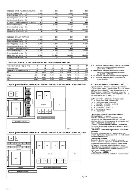
• Lay-out quadro elettrico unità <strong>CWA</strong>/E-<strong>CWA</strong>/<strong>ES</strong>-<strong>CWA</strong>/<strong>EX</strong>-<strong>CWA</strong>/<strong>ES</strong>X-<strong>CWR</strong>/E-<strong>CWR</strong>/<strong>ES</strong> <strong>185</strong> ÷ 300<br />
Canalina<br />
FV1 FV2<br />
TR IA<br />
Canalina<br />
FC1 FC2<br />
FV3 FV4<br />
Canalina<br />
Canalina<br />
Canalina<br />
FV5 FV6<br />
Canalina<br />
CE1<br />
KV1 KV2<br />
KV3 KV4<br />
KV5 KV6<br />
Canalina<br />
Morsettiera ausiliaria<br />
Canalina<br />
Canalina<br />
IG<br />
KC1 KC11 KC2 KC22<br />
Barra colleg. terre equipotenziali<br />
fig. 9<br />
• Lay-out quadro elettrico unità <strong>CWA</strong>/E-<strong>CWA</strong>/<strong>ES</strong>-<strong>CWA</strong>/<strong>EX</strong>-<strong>CWA</strong>/<strong>ES</strong>X-<strong>CWR</strong>/E-<strong>CWR</strong>/<strong>ES</strong> 370 ÷ 600<br />
TR IA<br />
FV1 FV2 FV3 FV4 FV5 FV6 FV7 FV8 FV9 FV10 FV11 FV12<br />
Canalina<br />
KV1 KV2 KV3 KV4 KV5 KV6 KV7 KV8 KV9 KV10 KV11 KV12<br />
Canalina<br />
Canalina<br />
FC1 FC2 FC3 FC4<br />
Canalina<br />
IG<br />
4.3 D<strong>ES</strong>CRIZIONE QUADRO ELETTRICO<br />
Il quadro elettrico è dotato di sezionatore generale con<br />
funzione di bloccoporta. L’alimentazione dei circuiti ausiliari<br />
a 230 V e di controllo a 24 V viene derivata internamente<br />
dall’alimentazone trifase. Disposizione dei componenti<br />
elettrici nel QE di macchine a 2 e a 4 compressori con 4, 6,<br />
8 e 12 ventilatori: vedi fig. 9 e fig. 10.<br />
CE1= Controllore elettronico a microprocessore<br />
FC = Fusibili protezione compressore<br />
FV = Fusibili protezione ventilatore<br />
IA = Interruttore automatico ausiliario<br />
IG = Interruttore generale<br />
KC = Contattore compressore<br />
KV = Contattore ventilatore<br />
TR = Trasformatore<br />
• Morsettiera d’interfaccia con i componenti<br />
principali esterni al quadro<br />
Permette di remotare, mediante contatti puliti,<br />
l’accensione e lo spegnimento della macchina, la<br />
selezione del tipo di funzionamento, la segnalazione di<br />
blocco e il comando pompa utenza.<br />
• Fusibili a protezione compressore e ventilatore<br />
Dispositivo a protezione da sovraccorrenti e correnti di<br />
corto circuito.<br />
• Interruttore automatico di protezione sul circuito<br />
ausiliario<br />
Dispositivo elettromeccanico di sezionamento con<br />
funzioni di protezione da sovracorrenti e correnti di corto<br />
circuito a riarmo manuale.<br />
• Interruttore generale<br />
Dispositivo di sezionamento dell’alimentazione a<br />
comando manuale. È provvisto di contatti ausiliari che<br />
permettono l’interruzione del circuito ausiliario prima<br />
dell’apertura dei contatti principali dell’interruttore.<br />
• Contattore di potenza compressore e ventilatore<br />
Dispositivo elettromeccanico pilotato dalla scheda<br />
elettronica a microprocessore.<br />
• Trasformatore V 230/24<br />
Fornisce l’alimentazione di controllo in bassa tensione.<br />
Canalina<br />
CE1<br />
KC1<br />
KC11<br />
KC2 KC22 KC3 KC33 KC4 KC44<br />
Canalina<br />
Barra colleg. terre equipotenziali<br />
Morsettiera ausiliaria<br />
fig. 10<br />
10


