Descrizione quadro Il quadro elettrico ZC3 è adatto al ... - Tribpt
Descrizione quadro Il quadro elettrico ZC3 è adatto al ... - Tribpt
Descrizione quadro Il quadro elettrico ZC3 è adatto al ... - Tribpt

Create successful ePaper yourself
Turn your PDF publications into a flip-book with our unique Google optimized e-Paper software.
CANCELLI AUTOMATICI<br />
SERIE Z | Z SERIES / SÉRIE Z | BAUREIHE Z | SERIE Z<br />
SCHEDA COMANDO<br />
CONTROL BOARD<br />
CARTE DE COMMANDE<br />
STEUERPLATINE<br />
TARJETA DE MANDO<br />
<strong>ZC3</strong><br />
Documentazione<br />
Tecnica<br />
S33<br />
rev. 2.2<br />
09/2001<br />
© CAME<br />
CANCELLI<br />
AUTOMATICI<br />
319S33<br />
320 mm<br />
120 mm<br />
240 mm<br />
145 mm<br />
ITALIANO<br />
CARATTERISTICHE GENERALI<br />
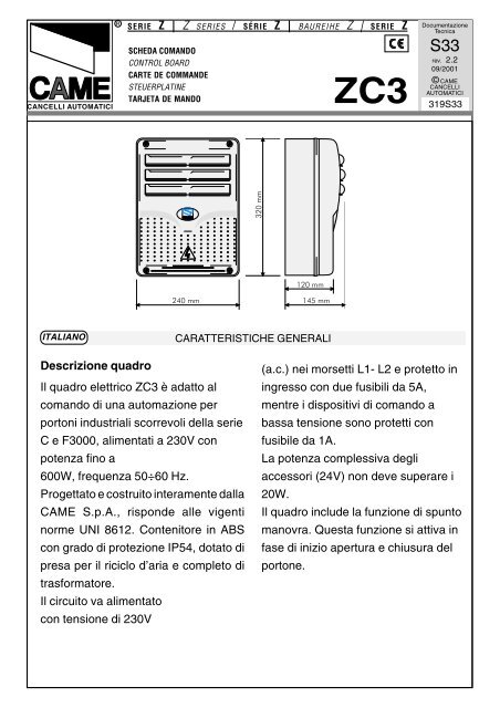
<strong>Descrizione</strong> <strong>quadro</strong><br />
<strong>Il</strong> <strong>quadro</strong> <strong>elettrico</strong> <strong>ZC3</strong> è <strong>adatto</strong> <strong>al</strong><br />
comando di una automazione per<br />
portoni industri<strong>al</strong>i scorrevoli della serie<br />
C e F3000, <strong>al</strong>imentati a 230V con<br />
potenza fino a<br />
600W, frequenza 50÷60 Hz.<br />
Progettato e costruito interamente d<strong>al</strong>la<br />
CAME S.p.A., risponde <strong>al</strong>le vigenti<br />
norme UNI 8612. Contenitore in ABS<br />
con grado di protezione IP54, dotato di<br />
presa per il riciclo d’aria e completo di<br />
trasformatore.<br />
<strong>Il</strong> circuito va <strong>al</strong>imentato<br />
con tensione di 230V<br />
(a.c.) nei morsetti L1- L2 e protetto in<br />
ingresso con due fusibili da 5A,<br />
mentre i dispositivi di comando a<br />
bassa tensione sono protetti con<br />
fusibile da 1A.<br />
La potenza complessiva degli<br />
accessori (24V) non deve superare i<br />
20W.<br />
<strong>Il</strong> <strong>quadro</strong> include la funzione di spunto<br />
manovra. Questa funzione si attiva in<br />
fase di inizio apertura e chiusura del<br />
portone.
ENGLISH<br />
GENERAL CHARACTERISTICS<br />
Description of control panel<br />
The <strong>ZC3</strong> electric panel is suitable for<br />
controlling the automation of series C<br />
and F3000, 230V sliding industri<strong>al</strong><br />
gates, with up to 600W power and 50-<br />
60 Hz frequency.<br />
Wholly designed and built by CAME<br />
S.p.A., it meets UNI 8612 regulations<br />
in force. ABS Case with an IP54 protective<br />
level, with air recycling inlet and<br />
transformer.<br />
The circuit requires 230V (a.c.) at termin<strong>al</strong><br />
blocks L1- L2 and the inlet is protected<br />
with two 5A fuses, whilst the low<br />
voltage command devices are protected<br />
by a 1A fuse.<br />
The accessories’ tot<strong>al</strong> wattage (24V)<br />
must not exceed 20W.<br />
The panel includes a manoeuvre pickup<br />
function. This function is activated<br />
during the initi<strong>al</strong> phase of the gate’s<br />
opening and closing.<br />
Safety<br />
Photocells can be connected to obtain:<br />
- Re-opening during closure (2-C1), if<br />
the photocells identify an obstacle<br />
while the gate is closing, they will<br />
reverse the direction of movement until<br />
the gate is completely open;<br />
- Re-closing during opening (2-CX, see<br />
dip n°8 to OFF - 9 to OFF), if the<br />
photocells identify an obstacle while<br />
the gate is opening, they will reverse<br />
the direction of movement until the<br />
gate is completely close;<br />
- Parti<strong>al</strong> stop, shutdown of moving<br />
gate, with activation of an automatic<br />
closing cycle (2-CX, dip n°8 OFF - 9<br />
ON);<br />
- Tot<strong>al</strong> stop (1-2), shutdown of gate<br />
movement without automatic closing; a<br />
pushbutton or radio remote control<br />
must be actuated to resume<br />
movement.<br />
N.B: If an NC safety contact (2-C1, 2-<br />
CX, 1-2) is opened, the LED (pag.12<br />
-n°8) will flash to indicate this fact;<br />
- Obstacle presence detection. When<br />
the motor is stopped (gate is closed,<br />
open or h<strong>al</strong>f-open after an emergency<br />
stop command), the transmitter and<br />
the control pushbutton will be<br />
deactivated if an obstacle is detected<br />
by one of the safety devices (for<br />
example, the photocells);<br />
- Safety test function. The control unit<br />
will now check the safety system every<br />
time an opening or closing command is<br />
given (see p.18).<br />
Accessories which can be<br />
connected to this unit<br />
- Cycle lamp. The lamp which lights the<br />
manoeuvring zone: it remains lit from<br />
the moment the doors begin to open<br />
-4-
until they are completely closed<br />
(including the time required for the<br />
automatic closure). In case automatic<br />
closure is not enabled, the lamp<br />
remains lit only during movement (E-<br />
EX, dip n°16 OFF - 17 ON);<br />
-Courtesy Light. A light that illuminates<br />
the manoeuvring zone; after an opening<br />
command, the light remains on for<br />
a fixed time of 5 minutes and 30 seconds<br />
(E-EX, dip n°16 ON - 17 OFF);<br />
- Open gate pilot lamp. It is a light that<br />
indicates the sliding gate’s open<br />
position and turns off when the gate<br />
activates the closing end-stop.<br />
Other functions<br />
- Automatic closing. The automatic<br />
closing timer is automatic<strong>al</strong>ly activated<br />
at the end of the opening cycle. The<br />
preset, adjustable automatic closing<br />
time is automatic<strong>al</strong>ly interrupted by the<br />
activation of any safety system, and is<br />
deactivated after a STOP command or<br />
in case of power failure;<br />
-Parti<strong>al</strong> opening. Opening of the gate to<br />
<strong>al</strong>low for foot traffic; activated by<br />
connecting to termin<strong>al</strong>s 2-3P and<br />
adjusted with the AP-PARZ. trimmer.<br />
With this function, the automatic<br />
closing can vary in the following way:<br />
1) Dip 12 set to ON: after a parti<strong>al</strong><br />
opening, the time for automatic closing<br />
functions independently of the adjustment<br />
of the TCA trimmer and of the position<br />
of Dip 1; it is set at 8 seconds.<br />
2) Dip 12 set to OFF: after a parti<strong>al</strong><br />
opening, the time for automatic closing<br />
is adjustable only if Dip 1 is set to ON.<br />
- "Operator present". Gate operates<br />
only when the pushbutton is held down<br />
(the radio remote control system is<br />
deactivated);<br />
- Pre-flashing. After an opening or<br />
closing command, the flasher<br />
connected to the W-E flashes for 5<br />
seconds before beginning the procedure;<br />
-Type of command:<br />
-Open-stop-close-stop by button and<br />
transmitter;<br />
-Open-close by button and transmitter;<br />
-Open only by transmitter.<br />
Adjiustments<br />
- Operating time;<br />
- Automatic closure time;<br />
- Parti<strong>al</strong> opening time.<br />
Caution! Disconnect the unit<br />
from the main power lines before<br />
carrying out any operation inside the<br />
unit.<br />
-5-
ON<br />
1 2 3 4 5 6 7 8 9 10<br />
ON<br />
11 12 13 14 15 16 17 18 19 20<br />
SCHEDA BASE - MOTHERBOARD - CARTE BASE - GRUNDPLATINE - TARJETA BASE<br />
12<br />
RENO<br />
1 2 3 4<br />
0 12 24<br />
SPUNTO<br />
Nota: collegare i fili neri che<br />
fuoriescono d<strong>al</strong>la scheda sui<br />
connettori del condensatore.<br />
5 6 7 8 9<br />
T.L. T.C.A. AP.PARZ.<br />
NB: connect the black wires coming<br />
out of the board to the condenser’s<br />
connectors.<br />
3<br />
4<br />
US. ACCESSORI 1A<br />
10<br />
Note: connecter les fils noirs qui<br />
sortent de la carte sur les<br />
connecteurs du condensateur.<br />
US. LINEA 5A<br />
QUADRO COMANDO<br />
<strong>ZC3</strong><br />
AF<br />
11<br />
Hinweis: Die schwarzen Kabel, die<br />
von der Karte wegführen, an die<br />
Verbinder am Kondensator<br />
anschließen.<br />
2<br />
1<br />
Nota: conectar los hilos negros<br />
que s<strong>al</strong>en de la tarjeta en los<br />
conectores del condensador.<br />
ITALIANO<br />
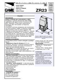
COMPONENTI PRINCIPALI<br />
1 Morsettiere di collegamento<br />
2 Fusibili di linea 5A<br />
3 Fusibile accessori 1A<br />
4 LED segn<strong>al</strong>azione tensione presente a 24V<br />
5 Trimmer di regolazione tempo lavoro<br />
6 Trimmer di regolazione tempo di chiusura automatica<br />
7 Trimmer di regolazione apertura parzi<strong>al</strong>e<br />
8 LED segn<strong>al</strong>azione<br />
9 Pulsanti memorizzazione codice<br />
10 Selettore funzioni (vedi pag.20)<br />
11 Innesto scheda radiofrequenza (vedi tabella)<br />
12 Limitatore di coppia motore (vedi pagina 16)<br />
-12-
ENGLISH<br />
MAIN COMPONENTES<br />
1 Termin<strong>al</strong> block for extern<strong>al</strong> conections<br />
2 Line fuses, 5A<br />
3 Fuse on accessory power line, 1A<br />
4 24V power-supply sign<strong>al</strong>ling LED<br />
5 Trimmer for adjustment operating time<br />
6 Trimmer for adjustment automatic closing<br />
7 Trimmer for adjustment parti<strong>al</strong> opening<br />
8 Sign<strong>al</strong> LED<br />
9 Radio-code save buttons<br />
10 20-Dip function switch (see pag.20)<br />
11 Socket AF radiofrequency board (see table)<br />
12 Motor torque limiter (see page 16)<br />
FRANÇAIS<br />
PRINCIPAUX COMPOSANTS<br />
1 Plaque à bornes de connexion<br />
2 Fusibles de ligne 5A<br />
3 Fusible accessoires 1A<br />
4 LED de sign<strong>al</strong>isation <strong>al</strong>imentation à 24V<br />
5 Trimmer de réglage temps de fonctionnement<br />
6 Trimmer de réglage fermeture automatique<br />
7 Trimmer de réglage temps ouverture partielle<br />
8 LED de sign<strong>al</strong>isation<br />
9 Boutons-poussoir mémorisation code radio<br />
10 Selecteur de fonctions à 20 interrupteurs à positions multiples (voir pag.20)<br />
11 Branchement carte radiofréquence AF (voir tableau)<br />
12 Limiteur de couple moteur (voir pag.16)<br />
DEUTSCH<br />
HAUPTKOMPONENTEN<br />
1 AnschlußKlemmenleiste<br />
2 Hauptsicherungen 5A<br />
3 Zubehör-Sicherung 1A<br />
4 LED Kontrolleuchte für Stromversorgung mit 24V<br />
5 Trimmer zur Einstellung Laufzeit<br />
6 Trimmer zur Einstellung der Schließautomatik<br />
7 Trimmer zur Einstellung Teilöffnung<br />
8 LED Kontrolleuchte zur Anzeige<br />
9 Knöpfe zum Abspeicher der Radiocodes<br />
10 Wählsch<strong>al</strong>ter für Funktionen mit 20 Dip (sehen S.20)<br />
11 Steckanschluß Funkfrequenze-Platine AF (sehen Tabelle)<br />
12 Drehmomentbegrenzer des Motors (sehen Seite 16)<br />
ESPANOL<br />
PRINCIPALES COMPONENTES<br />
1 Caja de bornes para las conexiónes<br />
2 Fusibles de línea 5A<br />
3 Fusible accesorios 1A<br />
4 Indicador luminoso de <strong>al</strong>imentación de 24V<br />
5 Trimmer de regulación tiempo trabajo<br />
6 Trimmer de regulación tiempo cierre automático<br />
7 Trimmer de regulación tiempo apertura parci<strong>al</strong><br />
8 LED de señ<strong>al</strong><br />
9 Teclas de memorización del código radio<br />
10 Selector de funciones con 20 dip (vedas pág.20)<br />
11 Conexión tarjeta radiofrecuencia AF (vedas tabla)<br />
12 Limitador de par motor (vedas pág.16)<br />
-13-
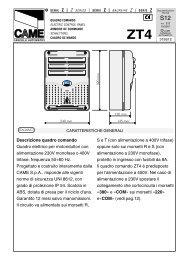
COLLEGAMENTI ELETTRICI - ELECTRICAL CONNECTIONS - BRANCHEMENTS ÉLECTRIQUES<br />
ELEKRISCHE ANSCHLÜSSE - CONEXIONES ELÉCTRICAS<br />
L1<br />
L2<br />
L1 L2 U V W E EX 10 11 TS 1 2 3 3P 4 5 7<br />
Alimentazione 230V (a.c.)<br />
230V (a.c.) power input<br />
Alimentation 230V (c.a.)<br />
Stromversorgung 230V (Wechselstrom)<br />
Alimentación 230V (a.c.)<br />
2 C1CXFCFA F B1B2<br />
U<br />
W<br />
V<br />
M<br />
Motore monofase 230V (a.c.) max. 600 W<br />
230V (a.c.) single-phase motor max. 600 W<br />
Moteur monophasé 230V (c.a.) max.600 W<br />
Einphasenmotor 230V (Wechselstrom) max. 600 W<br />
Motor monofásico 230V (a.c.) max. 600 W<br />
W<br />
E<br />
Uscita 230V (a.c.) in movimento<br />
(es.lampeggiatore - max. 25W)<br />
230V (a.c.) output in motion<br />
(e.g. flashing light - max. 25W)<br />
Sortie 230V (c.a.) en mouvement<br />
(ex. branchement clignotant - max. 25W)<br />
Ausgang 230V (Wechselstrom) in Bewegung<br />
(z.B. Blinker-Anschluß - max. 25W)<br />
S<strong>al</strong>ida de 230V (a.c.) en movimento<br />
(p.ej. conexión lámpara intermitente - max. 25W)<br />
U V W E EX<br />
E<br />
EX<br />
Uscita 230V (a.c.)<br />
lampada ciclo - max. 60W<br />
Output 230V (a.c.)<br />
max.60W - cycle lamp<br />
Sortie 230V (c.a.)<br />
lampe cycle - max. 60W<br />
Ausgang 230V (Wechselstrom)<br />
Betriebszyklus-Anzeigeleuchte - max.60W<br />
S<strong>al</strong>ida de 230V (a.c.)<br />
lámpara ciclo - max.60W<br />
Uscita 230V (a.c.)<br />
lampada cortesia - max. 60W<br />
Output 230V (a.c.)<br />
max.60W - courtesy lamp<br />
Sortie 230V (c.a.)<br />
lampe d’éclairage - max. 60W<br />
Ausgang 230V (Wechselstrom)<br />
Torbeleuchtung - max.60W<br />
S<strong>al</strong>ida de 230V (a.c.)<br />
lámpara cortesía - max.60W<br />
16 OFF - 17 ON<br />
ON<br />
11 12 13 14 15 16 17 18 19 20<br />
16 ON - 17 OFF<br />
ON<br />
U V W EEX<br />
11 12 13 14 15 16 17 18 19 20<br />
10<br />
11<br />
-14-<br />
Alimentazione accessori 24V (a.c.) max. 20W<br />
24V (a.c.)Powering accessories (max 20W)<br />
Alimentation accessoires 24V (c.a.) max. 20W<br />
Zubehörspeisung 24V (Wechselstrom) max. 20W<br />
Alimentación accesoios 24V (a.c.) max. 20W
10<br />
5<br />
Lampada spia (24V-3W max.) "portone aperto"<br />
(24V-3W max.) "gate-opened" sign<strong>al</strong> lamp<br />
Lampe-témoin (24V-3W max.) "portail ouverture"<br />
Sign<strong>al</strong>lampe (24V-3W max.) "Tor Öffnen"<br />
Lámpara indicadora (24V-3W max.) "puerta abierta"<br />
1<br />
2<br />
Pulsante stop (N.C.)<br />
Pushbutton stop (N.C.)<br />
Bouton-poussoir arrêt (N.F.)<br />
Stop-Taste (Ruhekontakt)<br />
Pulsador de stop (N.C.)<br />
2<br />
3<br />
Pulsante di apertura (N.O.)<br />
Pushbutton opens (N.O.)<br />
Bouton-poussoir de ouverture (N.O.)<br />
Taste (Arbeitskontakt) für Öffnen<br />
Pulsador de apertura (N.O.)<br />
2<br />
3P<br />
Pulsante per apertura parzi<strong>al</strong>e (N.O.)<br />
Button (N.O.) for parti<strong>al</strong> opening<br />
Bouton-poussoir (N.O.) pour ouverture parti<strong>al</strong><br />
Taste (Arbeitskontakt) für TeilÖffnung<br />
Pulsador (N.O.) para apertura parci<strong>al</strong><br />
2<br />
4<br />
Pulsante di chiusura (N.O.)<br />
Pushbutton closes (N.O.)<br />
Bouton-poussoir de ouverture (N.O.)<br />
Taste (Arbeitskontakt) für Schließen<br />
Pulsador de cierre (N.O.)<br />
2<br />
7<br />
Contatto radio e/o pulsante per comando (vedi dip p.20)<br />
Contact radio and/or button for control (see dip pag.20)<br />
Contact radio et/ou poussoir pour commande (dip p.20)<br />
Funkkontakt und/oder Taste Steuerart (sehen Dip S.20)<br />
Contacto radio y/o pulsador para mando (vedas dip p.20)<br />
2<br />
CX<br />
2<br />
C1<br />
Contatto (N.C.) di «richiusura durante la apertura»<br />
Contact (N.C.) for «re-closing during the opening»<br />
Contact (N.F.) de «réfermeture pendant la ouverture»<br />
Kontakt (Ruhekontakt) «erneutes Schließen beim Öffnen»<br />
Contacto (N.C.) para la «recierre<br />
8 OFF - 9 OFF<br />
en la fase de apertura»<br />
Contatto (N.C.) di «stop parzi<strong>al</strong>e»<br />
Contact (N.C.) for «parti<strong>al</strong> stop»<br />
Contact (N.F.) de «stop partiel»<br />
Kontakt (Ruhekontakt) «Teilstop»<br />
Contacto (N.C.) para la «parada parci<strong>al</strong>»<br />
1 2 3 4 5 6 7 8 9 10<br />
8 OFF - 9 ON<br />
Contatto (N.C.) di «riapertura durante la chiusura»<br />
Contact (N.C.) for «re-opening during the closing»<br />
Contact (N.F.) de «réouverture pendant la fermeture»<br />
Kontakt (Ruhekontakt) «Wiederöffnen beim Schliessen»<br />
Contacto (N.C.) para la «apertura en la fase de cierre»<br />
-15-<br />
ON<br />
1 2 3 4 5 6 7 8 9 10<br />
ON
US. LINEA 5A<br />
US. ACCESSORI 1A<br />
ON<br />
T.L. T.C.A. AP.PARZ.<br />
1 2 3 4 5 6 7 8 9 10<br />
ON<br />
11 12 13 14 15 16 17 18 19 20<br />
F<br />
FC<br />
Collegamento finecorsa chiude<br />
Connection limit switch closes<br />
Connexion fin de course fermeture<br />
Anschluß Endsch<strong>al</strong>lter Schließen<br />
Conexión fin de carrera cierre<br />
F<br />
FA<br />
Collegamento finecorsa apertura<br />
Connection limit switch opens<br />
Connexion fin de course ouverture<br />
Anschluß Endsch<strong>al</strong>lter Öffnen<br />
Conexión fin de carrera apertura<br />
B1<br />
B2<br />
Uscita contatto (N.O.) Portata contatto: 5A - 24V d.c.<br />
Contact output (N.O.) Resistive load: 5A - 24V d.c.<br />
Sortie contact (N.O.) Portée contact: 5A - 24V c.c.<br />
Ausgang Arbeitskontakt Stromfestigkeit: 5A-24V Gleichstrom<br />
S<strong>al</strong>ida contacto (N.O.) Carga resistiva: 5A - 24V d.c.<br />
Collegamento antenna<br />
Antenna connection<br />
Connexion antenne<br />
Antennenanschluß<br />
Conexión antena<br />
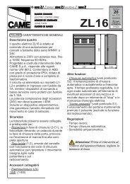
LIMITATORE DI COPPIA MOTORE / MOTOR TORQUE LIMITER / LIMITEUR DE COUPLE MOTEUR<br />
DREHMOMENTBEGRENZER DES MOTORS /LIMITADOR DE PAR MOTOR<br />
Per variare la<br />
coppia motrice,<br />
spostare il<br />
faston indicato<br />
(con filo di<br />
colore nero) su<br />
una delle 4<br />
posizioni; 1<br />
min. - 4 max<br />
To vary the<br />
motor torque,<br />
move the<br />
indicated faston<br />
to one of the<br />
four positions:<br />
1=min, 4=max<br />
Pour varier le<br />
couple du<br />
moteur,<br />
déplacer le<br />
connecteur<br />
indiqué sur<br />
l'une des 4<br />
positions; 1<br />
min. - 4 max.<br />
Zur Änderung<br />
des Motor-<br />
Drehmoments<br />
den angegebenen<br />
Faston auf<br />
eine der 4<br />
Stellungen<br />
positionieren: 1<br />
min. - 4 max.<br />
Para variar el<br />
par motor,<br />
desplazar el<br />
faston<br />
indicado hasta<br />
una de las 4<br />
posiciones; 1<br />
mín. - 4 máx.<br />
L2T<br />
2 3 4<br />
1 L1T<br />
SPUNTO<br />
0 12 24<br />
L2T<br />
1 2 3 4 L1T<br />
SPUNTO<br />
0 12 24<br />
AF<br />
QUADRO COMAN DO<br />
<strong>ZC3</strong><br />
L1T L2T CT VS 24 12 0<br />
-16-
ISTRUZIONI MONTAGGIO QUADRO S4340 - ASSEMBLY INSTRUCTIONS S4340 PANEL<br />
INSTRUCTIONS MONTAGE ARMOIRE S4340<br />
MONTAGEANWEISUNGEN SCHALTTAFEL S4340 - INSTRUCCIONES MONTAJE CUADRO S4340<br />
1<br />
Assemblare le cerniere a pressione<br />
Assemble the hinges by pressure<br />
Assembler les charnières à pression<br />
Setzen Sie die Druckscharniere zusammen.<br />
Ensamblar las bisagras a presión<br />
15 mm~<br />
scorrono per ruotare<br />
they must slide in order to turn<br />
elles glissent pour tourner<br />
laufen zum Drehen<br />
deslizan para girar<br />
!!<br />
2<br />
Inserire le cerniere nella scatola (sul lato<br />
destro o sinistro a scelta) e fermarle con le<br />
viti e le rondelle in dotazione<br />
Insert the hinges (on the right or left side,<br />
according to choice) and secure using the<br />
screws and washers supplied<br />
Placer les charnières (du côté droit ou<br />
gauche au choix) et les fixer avec les vis et<br />
les rondelles fournies de série<br />
Setzen Sie die Scharniere ein (je nach<br />
Wunsch auf der rechten oder linken Seite)<br />
und befestigen Sie sie mit den mitgelieferten<br />
Schrauben und Unterlegscheiben<br />
Introducir las bisagras (en el lado izquierdo o<br />
derecho, a placer) y fijarlas con los tornillos<br />
y las arandelas suministradas a t<strong>al</strong> efecto<br />
295 mm<br />
3<br />
215 mm<br />
Posizionare e fissare la scatola del<br />
<strong>quadro</strong><br />
Position and secure the control<br />
panel housing<br />
Placer et fixer la boîte de l'armoire<br />
Plazieren Sie das Gehäuse der<br />
Sch<strong>al</strong>ttafel und befestigen Sie es.<br />
Colocar y sujetar la caja del cuadro<br />
4<br />
Inserire a scatto il coperchio sulle cerniere,<br />
chiuderlo e fissarlo con le viti in dotazione<br />
Snap the cover onto the hinges and secure<br />
using the screws supplied.<br />
Assembler par encliquetage le couvercle sur<br />
les charnières et fixer le couvercle avec les vis<br />
fournies de série<br />
Lassen Sie den Deckel in den Scharnieren<br />
einrasten und befestigen Sie ihn mit den<br />
mitgelieferten Schrauben.<br />
Introducir la tapa en las bisagras hasta oír un<br />
chasquido y fijar la tapa con los tornillos<br />
suministrados a t<strong>al</strong> efecto.<br />
-17-
TEST FUNZIONAMENTO FOTOCELLULE - PHOTOCELL FUNCTION TEST<br />
TEST FONCTIONNEMENT PHOTOCELLULES<br />
TEST FÜR DAS FUNKTIONIEREN DER LICHTSCHRANKEN - TEST FUNCIONAMIENTO FOTOCELULAS<br />
FIG. 1<br />
ABB. 1<br />
FIG. 2<br />
ABB. 2<br />
Rx<br />
+ - + -<br />
N.O.<br />
C.<br />
N.C.<br />
10 2 TX C NC<br />
TX 2<br />
FUSIBILE 200mA<br />
+ - -<br />
«DOC»<br />
10 11 TS 1 2 3 3P 4 5 7<br />
«DIR»<br />
10 11 TS 1 2 3 3P 4 5 7<br />
ITALIANO<br />
Consente <strong>al</strong>la centr<strong>al</strong>ina di verificare<br />
l'efficienza dei dispositivi di<br />
sicurezza (fotocellule) dopo ogni<br />
comando di apertura o di chiusura.<br />
Un'eventu<strong>al</strong>e anom<strong>al</strong>ia delle<br />
fotocellule è identificata con un<br />
lampeggio del led sul <strong>quadro</strong> comando,<br />
di conseguenza annulla<br />
qu<strong>al</strong>siasi funzione del<br />
radiocomando e dei pulsanti.<br />
Collegamento <strong>elettrico</strong> per il funzionamento<br />
del test di sicurezza.<br />
I trasmettitori e i ricevitori delle<br />
fotocellule devono essere collegati<br />
come illustrati nelle fig.1 e fig.2.<br />
- selezionare il dip 13 in ON per<br />
attivare il funzionamento del test.<br />
IMPORTANTE: Quando si esegue la<br />
funzione test di sicurezza, VERIFI-<br />
CARE che NON CI SIANO PONTI tra<br />
i contatti 2-CX, 2-C1 e, se non<br />
utilizzati, escluderli tramite dip 7 e 8.<br />
ENGLISH<br />
It <strong>al</strong>lows the gearcase to check the<br />
efficiency of the safety devices<br />
(photoelectric cells) after each<br />
command to open or close. Any<br />
anom<strong>al</strong>y of the photoelectric cells is<br />
identified with a flash of the LED on the<br />
control panel; therefore <strong>al</strong>l functions of<br />
the remote control and buttons are<br />
cancelled.<br />
Electric<strong>al</strong> connection for safety-test<br />
functioning.<br />
The transmitters and the receivers of<br />
the photoelectric cells must be<br />
connected as illustrated in figs.1 and 2.<br />
- move dip switch 13 to ON, which will<br />
activate the test function.<br />
IMPORTANT: When the safety test<br />
function is performed, check that there<br />
are no jumpers between contacts 2-<br />
CX, 2-C1 and, if not being used,<br />
exclude them using dip switches 7 and<br />
8.<br />
-18-
FUS . LINEA 5A<br />
FUS . A CCE SSORI 1A<br />
ON<br />
T.L. T.C. A. AP .PAR Z.<br />
1 2 3 4 5 6 7 8 9 10<br />
ON<br />
11 12 13 14 15 16 17 18 19 20<br />
SELEZIONI FUNZIONI - SELECTION OF FUNCTIONS - SÉLECTION FONCTIONS<br />
FUNKTIONSWAHL- SELECCIÓN DE LAS FUNCIONES<br />
DIP-SWITCHES (1-10)<br />
AF<br />
QUADRO COMAN DO<br />
<strong>ZC3</strong><br />
ON<br />
ON<br />
O 1 2 3 4 5 6 7 8 9 10<br />
ITALIANO<br />
1 ON Chiusura automatica attivata; (1OFF - disattivata)<br />
2 ON "Apre-stop-chiude-stop" con pulsante (2-7) e radiocomando (scheda AF<br />
inserita) attivata;<br />
2 OFF "Apre-chiude" con pulsante (2-7) e radiocomando (scheda AF inserita) attiv.;<br />
3 ON "Sola apertura" con radiocomando (scheda AF inserita) attivata; (3OFF -<br />
disattivata)<br />
4 OFF "Uomo presente" (esclude il funzionamento del radiocomando) disattivata;<br />
(4ON - attivata)<br />
5 ON Prelampeggio attivato; (5OFF - disattivato)<br />
6 ON Rilevazione di presenza ostacolo attivata; (6OFF - disattivata)<br />
7 OFF Riapertura in fase di chiusura attivata; con dispositivo di sicurezza collegato<br />
ai morsetti 2-C1, (se non viene utilizzato il dispositivo, selezionare il dip in ON)<br />
8 OFF-9 OFF Richiusura in fase di apertura attivata; con dispositivo di sicurezza<br />
collegato ai morsetti 2-CX;<br />
8 OFF-9 ON Stop parzi<strong>al</strong>e attivata; con dispositivo di sicurezza collegato ai<br />
morsetti 2-CX;<br />
(se non vengono utilizzati i dispositivi su 2-CX, posizionare il dip 8 in ON)<br />
10OFF Stop tot<strong>al</strong>e attivato con pulsante collegato ai morsetti 1-2, (se non viene<br />
utilizzato, selezionare il dip in ON)<br />
-20-
ENGLISH<br />
1 ON Automatic closure activated; (1OFF-deactivated)<br />
2 ON "Open-stop-close-stop" with button (2-7) and radio control (AF board inserted)<br />
activated;<br />
2 OFF "Open-close" with button (2-7) and radio control (AF board inserted) activated;<br />
3 ON "Only opening" with radio control (AF board inserted) activated; (3OFFdeactivated)<br />
4 OFF "Operator present" (radio remote control is deactivated when function is<br />
selected) deactivated; (4ON -activated)<br />
5 ON Pre-flashing activated; (5OFF-deactivated)<br />
6 ON Obstacle detection device activated; (6OFF-deactivated)<br />
7 OFF Re-opening in closing phase activated; connect the safety device on termin<strong>al</strong>s<br />
2-C1, (if not used, set the dip-switch to ON)<br />
8 OFF-9 OFF Re-closing activated; connect the safety device on termin<strong>al</strong>s 2-CX,<br />
8 OFF-9 ON Parti<strong>al</strong> stop activated; connect the safety device on termin<strong>al</strong>s 2-CX,<br />
(if the devices on the 2-CX termin<strong>al</strong>s are not used, set Dip 8 to ON)<br />
10OFF Tot<strong>al</strong> stop activated; connect the safety device on termin<strong>al</strong>s 1-2, (if not used,<br />
set the dip-switch to ON)<br />
FRANÇAIS<br />
1 ON Fermeture automatique activée; (1OFF-désactivée)<br />
2 ON "Ouvre-stop-ferme-stop" avec bouton (2-7) et commande-radio (carte AF<br />
insérée) activée;<br />
2 OFF "Ouvre-ferme" avec bouton (2-7) et commande-radio (carte AF insérée)<br />
activée;<br />
3 ON "Soulement ouverture" avec commande-radio (carte AF insérée) activée;<br />
(3OFF-désactivée)<br />
4 OFF "Homme mort" (exclut la fonction radiocommande) désactivée; (4ON-activée)<br />
5 ON Preclignotement activée; (5OFF-désactivée)<br />
6 ON Dispositif de détection d'obstacle activée; (6OFF-désactivée)<br />
7 OFF Réouverture en phase de fermeture activée; relier le dispositif de sécuritè<br />
aux bornes 2-C1; (s'il n'est pas utilisé, positionner l'interrupteur à positions<br />
multiples sur ON)<br />
8 OFF-9 OFF Réfermeture en phase de ouverture activée; relier le dispositif de<br />
sécuritè aux bornes 2-CX;<br />
8 OFF-9 ON Stop partiel activée; relier le dispositif de sécurite aux bornes 2-CX;<br />
(si les dispositifs sur 2-CX ne sont pas utilisés, positionner le dip 8 sur ON)<br />
10OFF Stop tot<strong>al</strong> activée relier le dispositif de sécurite aux bornes 1-2, (s'il n'est pas<br />
utilisé, positionner l'interrupteur à positions multiples sur ON)<br />
-21-
FUS . LINEA 5A<br />
FUS . ACCE SSORI 1A<br />
ON<br />
T.L. T.C. A. AP .PAR Z.<br />
1 2 3 4 5 6 7 8 9 10<br />
ON<br />
11 12 13 14 15 16 17 18 19 20<br />
DIP-SWITCHES (11-20)<br />
AF<br />
QUADRO COMAN DO<br />
<strong>ZC3</strong><br />
ON<br />
11 12 13 14 15 16 17 18 19 20<br />
ON<br />
O<br />
ITALIANO<br />
11 Non utlizzato, tenere il dip in posizione «OFF»<br />
12 ON Apertura parzi<strong>al</strong>e attivata; (la chiusura automatica è fissa a 8”)<br />
12 OFFApertura parzi<strong>al</strong>e attivata; (la chiusura automatica è regolabile mediante<br />
trimmer, se inserita)<br />
13 ON Test di sicurezza per la verifica dell’efficenza delle fotocellule (vedi pagina 18)<br />
attivata; (13 OFF-disattivata)<br />
14 Non utlizzato, tenere il dip in posizione «OFF»<br />
15 Non utlizzato, tenere il dip in posizione «OFF»<br />
16 ON Lampada di cortesia attivata; (16 OFF-disattivata)<br />
17 ON Lampada di ciclo attivata; (17 OFF-disattivata)<br />
18 Non utlizzato, tenere il dip in posizione «OFF»<br />
19 Non utlizzato, tenere il dip in posizione «OFF»<br />
20 Non utlizzato, tenere il dip in posizione «OFF»<br />
ENGLISH<br />
11 Not used, keep the dip in position "OFF"<br />
12 ON Parti<strong>al</strong> opening (automatic closing is fixed at 8 seconds) activated;<br />
12 OFFParti<strong>al</strong> opening (automatic closing is adjusted with the trimmer, if inserted)<br />
activated;<br />
13 ON Activates safety test that checks the photocells proper operation (see pag.18)<br />
activated; (13OFF-disabled)<br />
14 Not used, keep the dip in position "OFF"<br />
15 Not used, keep the dip in position "OFF"<br />
16 ON Courtesy light function activated; (16OFF-disabled)<br />
17 ON Lamp cycle function activated; (17OFF-disabled)<br />
18 Not used, keep the dip in position "OFF"<br />
19 Not used, keep the dip in position "OFF"<br />
20 Not used, keep the dip in position "OFF"<br />
-23-
FUS . LINEA 5A<br />
FUS . ACCESSORI 1A<br />
ON<br />
T.L. T.C. A. AP .PAR Z.<br />
1 2 3 4 5 6 7 8 9 10<br />
ON<br />
11 12 13 14 15 16 17 18 19 20<br />
REGOLAZIONI - ADJUSTMENTS - RÉGLAGES - EINSTELLUNGEN - REGULACIONES<br />
ENGLISH<br />
REGOLAZIONE TRIMMERS<br />
TRIMMERS ADJUSTMENT<br />
RÉGLAGE TRIMMERS<br />
EINTELLUNG TRIMMERS<br />
REGULACIÓN TRIMMERS<br />
T.L. T.C.A. AP.PARZ.<br />
QUADRO COMAN DO<br />
<strong>ZC3</strong><br />
AF<br />
ITALIANO<br />
Trimmer T.L. = Regolazione tempo<br />
di lavoro da un minimo di 10 secondi<br />
a un massimo di 150 secondi.<br />
Trimmer T.C.A. = Regolazione<br />
tempo di chiusura automatica da un<br />
minimo di 0 secondi a un massimo<br />
di 120 sec.<br />
Trimmer AP.PARZ. = Regolazione di<br />
apertura parzi<strong>al</strong>e da un minimo di 0<br />
secondi a un massimo di 16 secondi.<br />
FRANÇAIS<br />
Trimmer T.L. = Adjusts of operating<br />
time from a minimum of 10 seconds to<br />
a maximum of 150 seconds.<br />
Trimmer T.C.A. = Adjusts automatic<br />
closing time from a minimum of 0<br />
seconds to a maximum of 120<br />
seconds.<br />
Trimmer AP.PARZ. = Adjusts parti<strong>al</strong><br />
opening from a minimum of 0 seconds<br />
to a maximum of 16 seconds.<br />
Trimmer T.L. = Réglage du temps de<br />
fonctionnement d’un minimum de<br />
10 secondes à un maximun de 150<br />
secondes.<br />
Trimmer T.C.A. = Réglage du temps<br />
de fermeture automatique d'un<br />
minimum de 0 secondes à un<br />
maximun de 120 secondes.<br />
Trimmer AP.PARZ. = Réglage d'ouverture<br />
parti<strong>al</strong> d'un minimum de 0<br />
secondes à un maximun de 16 sec.<br />
DEUTSCH<br />
Trimmer T.L. = Laufzeit mit<br />
mindestens 10. Sekunden und<br />
höchstens 150 Sekunden eingestellt<br />
werden kann.<br />
Trimmer T.C.A. = Timer, auf dem die<br />
Verzögerung für das automatische<br />
Schließen mit mindestens 0 Sekunden<br />
und höchstens 120 Sekunden<br />
eingestellt werden kann.<br />
Trimmer AP.PARZ. = Timer, auf dem<br />
die Verzögerung für das Teilöffnung<br />
mit mindestens 0 Sekunden und<br />
höchstens 16 Sekunden eingestellt<br />
werden kann.<br />
ESPANOL<br />
Trimmer T.L. = Regulación tiempo<br />
de trabajo, desde un mínimo de 10<br />
segundos hasta un máximo de 150<br />
segundos.<br />
Trimmer T.C.A. = Regulación del<br />
tiempo de cierre automático, desde<br />
un mínimo de 0 segundos hasta un<br />
máximo de 120 segundos.<br />
Trimmer AP.PARZ. = Regulación de<br />
apertura parci<strong>al</strong>, desde un mínimo<br />
de 0 segundos hasta un máximo de<br />
16 segundos.<br />
-25-
COLLEGAMENTO PER 2 MOTORI ABBINATI - CONNECTIONS FOR 2 COMBINED MOTORS<br />
CONNEXIONS POUR 2 MOTEURS ACCOUPLÉS<br />
ANSCHLUSSE FÜR 2 PARALLELGESCHALTETEN MOTOREN - CONEXIÓN PARA 2 MOTORES ACOPLADOS<br />
ITALIANO<br />
Nel caso di inst<strong>al</strong>lazione di due motori<br />
abbinati, procedere nel seguente modo:<br />
1) Coordinare il senso di marcia dei<br />
motoriduttori "A" e "B", modificando la<br />
rotazione del motore "B" ed eventu<strong>al</strong>e<br />
collegamento del gruppo finecorsa;<br />
2) Assicurarsi che sia inserito il ricevitore<br />
radio (AF) sul <strong>quadro</strong> del motore "A";<br />
3) Su entrambi i quadri devono essere<br />
fatte le stesse regolazioni e funzioni;<br />
4) <strong>Il</strong> pulsante di apertura parzi<strong>al</strong>e (2-3P)<br />
va collegato sulla morsettiera del <strong>quadro</strong><br />
del motore interessato;<br />
5) Eseguire i collegamenti elettrici tra le<br />
morsettiere del <strong>quadro</strong> "A" e "B" come da<br />
«Fig. A».<br />
N.B. Per comandare le automazioni con<br />
l'utilizzo del radiocomando occorre,<br />
memorizzare il codice del trasmettitore<br />
sul can<strong>al</strong>e CH2 della scheda base del<br />
motore "A" (vedi programmazione del<br />
radiocomando a pagina 26). Dopo la<br />
memorizzazione del codice, collegare i<br />
contatti B1-B2 sui contatti 2-7. <strong>Il</strong> comando<br />
di apertura su 2-7 è a seconda della<br />
selezione effettuata sui dip 2-3 selezionati<br />
su entrambe le schede (vedi<br />
«fig.B»).<br />
A<br />
2<br />
1<br />
B<br />
Scheda radiofrequenza “AF”<br />
"AF" Radio frequency board<br />
Carte frequence radio "AF"<br />
Radiofrequenzkarte «AF»<br />
Tarjeta radiofrecuencia «AF»<br />
ENGLISH<br />
In case two combined motors are inst<strong>al</strong>led,<br />
proceed in the following manner:<br />
1) Co-ordinate the direction of the “A”<br />
and “B” reduction gears, modifying “B”<br />
gear’s rotation and the possible<br />
connection of the end-stop set.<br />
2) Make sure that the (AF) radio receiver<br />
is connected to the motor "A" control<br />
panel;<br />
3) The same settings and functions must<br />
be made on both control panels;<br />
4) The parti<strong>al</strong> aperture button (2-3P)<br />
should be connected to the termin<strong>al</strong><br />
board of the corresponding motor control<br />
-26-<br />
AF<br />
Scheda base del motore "A"<br />
"A" Motor main board<br />
Carte de base du moteur "A"<br />
Basiskarte vom Motor "A"<br />
Tarjeta base del motor «A»
panel;<br />
5) Make the necessary electric connections<br />
between the termin<strong>al</strong> boards of<br />
the "A" and "B" panels as in «Fig. A»;<br />
N.B. In order to control the automation<br />
with the remote control, it is necessary<br />
to memorize the transmitter’s code on<br />
channel CH2 of motor "A’s" motherboard<br />
(see radio remote control on page 26).<br />
B1-B2 exit control is obtained after<br />
memorization. After that, connect the<br />
B1-B2 exit on circuits 2-7 to get control<br />
according to the selection made on dip<br />
switch 2-3 on both panels (see «fig. B»).<br />
3<br />
ON<br />
Scheda base del motore "A"<br />
"A" Motor main board<br />
Carte de base du moteur "A"<br />
Basiskarte vom Motor "A"<br />
Tarjeta base del motor «A»<br />
T.L. T.C.A. AP.PARZ.<br />
1 2 3 4 5 6 7 8 9 10<br />
ON<br />
11 12 13 14 15 16 17 18 19 20<br />
FRANÇAIS<br />
Pour inst<strong>al</strong>ler deux moteurs accouplés,<br />
procéder comme suit:<br />
1) Coordonner le sens de marche des<br />
motoréducteurs "A" et "B" en modifiant la<br />
rotation du moteur "B" et le branchement<br />
éventuel du groupe des interrupteurs de<br />
fin de course;<br />
2) Contrôler si le récepteur radio (AF) est<br />
branché sur le tableau du moteur "A";<br />
3)Les mêmes réglages et fonctions<br />
doivent être effectués sur les deux<br />
tableaux.<br />
4) Brancher le bouton d’ouverture<br />
partielle (2-3P) à la plaque à bornes du<br />
tableau du moteur intéressé;<br />
5) Effectuer les branchements électriques<br />
entre les plaques à borne du<br />
tableau "A" et "B", comme indiqué sur la<br />
«Fig. A»;<br />
N.B.: Pour commander les automations<br />
à l'aide de la radiocommande,<br />
mémoriser le code de l'émetteur sur le<br />
can<strong>al</strong> CH2 de la carte de base du<br />
moteur "A" (voir radiocommande page<br />
26). Après la mémorisation, on obtient la<br />
commande à la sortie sur B1-B2.<br />
Brancher ensuite la sortie B1-B2 sur le<br />
contacts 2-7 pour obtenir la commande<br />
selon la sélection effectuée<br />
sur les commutateurs dip 2-3 sur les<br />
deux cartes (voir «fig. B»).<br />
Scheda base del motore "B"<br />
"B" Motor main board<br />
Carte de base du moteur "B"<br />
Basiskarte vom Motor "B"<br />
Tarjeta base del motor «B»<br />
4<br />
ON<br />
T.L. T.C.A. AP.PARZ.<br />
1 2 3 4 5 6 7 8 9 10<br />
11 12 13 14 15 16 17 18 19 20<br />
Pulsante (N.O.) «Apertura parzi<strong>al</strong>e»<br />
«Parti<strong>al</strong> opening» button (N.O.)<br />
Bouton-poussoir (N.O.) «Ouverture parti<strong>al</strong>»<br />
Taste (Arbeitskontakt) «Teilöffnung»<br />
Pulsador (N.O.) «Apertura parci<strong>al</strong>»<br />
10 11 TS 1 2 3 3P 4 5 7<br />
ON<br />
-27-
5<br />
«Fig.A»<br />
«Abb.A»<br />
Morsettiera del <strong>quadro</strong> motore «A»<br />
Termin<strong>al</strong> board of the "A" motor control panel<br />
Plaque à bornes du tableau du moteur «A»<br />
Klemmbrett der Sch<strong>al</strong>ttafel vom Motor «A»<br />
Tablero de bornes del cuadro motor «A»<br />
Morsettiera del <strong>quadro</strong> motore «B»<br />
Termin<strong>al</strong> board of the "B" motor control panel<br />
Plaque à bornes du tableau du moteur «B»<br />
Klemmbrett der Sch<strong>al</strong>ttafel vom Motor «B»<br />
Tablero de bornes del cuadro motor «B»<br />
10 11 TS 1 2 3 3P 4 5 7 2 C1 CX FC FA F B1 B2<br />
10 11 TS 1 2 3 3P 4 5 7 2 C1 CX FC FA F B1 B2<br />
(1-2)<br />
(2-3)<br />
(2-4)<br />
(2-7)<br />
(2-C1)<br />
(2-CX)<br />
«Fig.B»<br />
«Abb.B»<br />
Morsettiera del <strong>quadro</strong> motore «A»<br />
Termin<strong>al</strong> board of the "A" motor control panel<br />
Plaque à bornes du tableau du moteur «A»<br />
Klemmbrett der Sch<strong>al</strong>ttafel vom Motor «A»<br />
Tablero de bornes del cuadro motor «A»<br />
Morsettiera del <strong>quadro</strong> motore «B»<br />
Termin<strong>al</strong> board of the "B" motor control panel<br />
Plaque à bornes du tableau du moteur «B»<br />
Klemmbrett der Sch<strong>al</strong>ttafel vom Motor «B»<br />
Tablero de bornes del cuadro motor «B»<br />
10 11 TS 1 2 3 3P 4 5 7 2 C1 CX FC FA F B1 B2<br />
10 11 TS 1 2 3 3P 4 5 7 2 C1 CX FC FA F B1 B2<br />
(1-2)<br />
(2-3)<br />
(2-4)<br />
(2-7)<br />
(2-C1)<br />
(2-CX)<br />
-29-