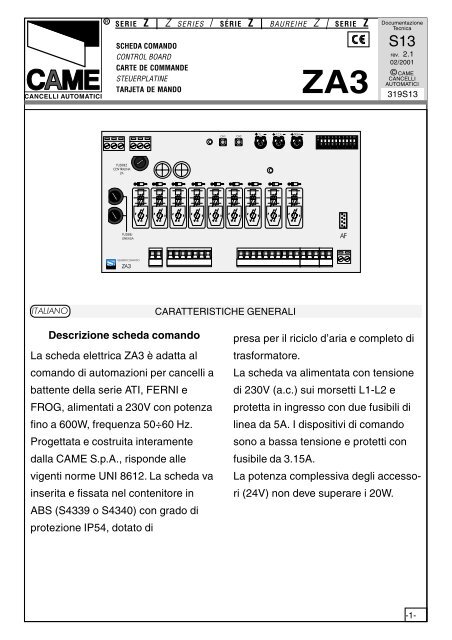
Descrizione scheda comando La scheda elettrica ZA3 è ... - Tribpt
Descrizione scheda comando La scheda elettrica ZA3 è ... - Tribpt
Descrizione scheda comando La scheda elettrica ZA3 è ... - Tribpt

Create successful ePaper yourself
Turn your PDF publications into a flip-book with our unique Google optimized e-Paper software.
CANCELLI AUTOMATICI<br />
SERIE Z | Z SERIES / SÉRIE Z | BAUREIHE Z | SERIE Z<br />
SCHEDA COMANDO<br />
CONTROL BOARD<br />
CARTE DE COMMANDE<br />
STEUERPLATINE<br />
TARJETA DE MANDO<br />
<strong>ZA3</strong><br />
Documentazione<br />
Tecnica<br />
S13<br />
rev. 2.1<br />
02/2001<br />
© CAME<br />
CANCELLI<br />
AUTOMATICI<br />
319S13<br />
CH1<br />
CH2<br />
T.L. T.C.A. TR2M.<br />
O 1 2 3 4 5 6 7 8 9 10<br />
N<br />
FUSIBILE<br />
CENTRALINA<br />
2A<br />
FUSIBILI<br />
LINEA 5A<br />
AF<br />
QUADRO COMANDO<br />
<strong>ZA3</strong><br />
ITALIANO<br />
CARATTERISTICHE GENERALI<br />
<strong>Descrizione</strong> <strong>scheda</strong> <strong>comando</strong><br />
<strong>La</strong> <strong>scheda</strong> <strong>elettrica</strong> <strong>ZA3</strong> è adatta al<br />
<strong>comando</strong> di automazioni per cancelli a<br />
battente della serie ATI, FERNI e<br />
FROG, alimentati a 230V con potenza<br />
fino a 600W, frequenza 50÷60 Hz.<br />
Progettata e costruita interamente<br />
dalla CAME S.p.A., risponde alle<br />
vigenti norme UNI 8612. <strong>La</strong> <strong>scheda</strong> va<br />
inserita e fissata nel contenitore in<br />
ABS (S4339 o S4340) con grado di<br />
protezione IP54, dotato di<br />
presa per il riciclo d’aria e completo di<br />
trasformatore.<br />
<strong>La</strong> <strong>scheda</strong> va alimentata con tensione<br />
di 230V (a.c.) sui morsetti L1-L2 e<br />
protetta in ingresso con due fusibili di<br />
linea da 5A. I dispositivi di <strong>comando</strong><br />
sono a bassa tensione e protetti con<br />
fusibile da 3.15A.<br />
<strong>La</strong> potenza complessiva degli accessori<br />
(24V) non deve superare i 20W.<br />
-1-
ENGLISH<br />
GENERAL CHARACTERISTICS<br />
Description of control board<br />
The <strong>ZA3</strong> electric board is suitable for<br />
controlling the automation of ATI,<br />
FERNI and FROG series 230V swing<br />
gates with up to 600W power and 50-<br />
60Hz frequency.<br />
Wholly designed and built by CAME<br />
S.p.A., it meets UNI 8612 regulations<br />
in force. The board is inserted and<br />
fixed to the ABS case (S4339 o<br />
S4340), which has an IP54 protection<br />
level, with air recycling inlet and<br />
transformer.<br />
The board requires 230V (a.c.) at<br />
terminal blocks L1-L2 and the inlet is<br />
protected with two 5A fuses. A 3.15A<br />
fuse protects the low voltage command<br />
devices.<br />
The accessories’ total wattage (24V)<br />
must not exceed 20W.<br />
Safety<br />
Photocells can be connected to<br />
obtain:<br />
- Re-opening during closure (2-C1), if<br />
the photocells identify an obstacle<br />
while the gate is closing, they will<br />
reverse the direction of movement until<br />
the gate is completely open;<br />
- Re-closing during opening (2-CX, dip<br />
8OFF-10OFF), if the photocells identify<br />
an obstacle while the gate is opening,<br />
they will reverse the direction of<br />
movement until the gate is completely<br />
closed;<br />
- Partial stop, shutdown of moving<br />
gate, with activation of an automatic<br />
closing cycle (2-CX);<br />
- Total stop (1-2), shutdown of gate<br />
movement without automatic closing; a<br />
pushbutton or radio remote control<br />
must be actuated to resume<br />
movement).<br />
NB: If an NC safety contact (2-C1, 2-<br />
CX, 1-2) is opened, the LED will flash<br />
to indicate this fact.<br />
Accessories which can be<br />
connected to this unit<br />
- “Gate open” signal light (10-5);<br />
- Cycle lamp. The lamp which lights the<br />
manoeuvring zone: it remains lit from<br />
the moment the doors begin to open<br />
until they are completely closed<br />
(including the time required for the<br />
automatic closure). In case automatic<br />
closure is not enabled, the lamp<br />
remains lit only during movement (E-<br />
E3);<br />
- Electric lock (11-S);<br />
-4-
Other functions available<br />
- Automatic closing. The automatic<br />
closing timer is automatically activated<br />
at the end of the opening cycle. The<br />
preset, adjustable automatic closing<br />
time is automatically interrupted by the<br />
activation of any safety system, and is<br />
deactivated after a STOP command or<br />
in case of power failure;<br />
- Obstacle presence detection: When<br />
the motor is stopped (gate is closed,<br />
open or half-open after an emergency<br />
stop command), the transmitter and<br />
the control pushbutton will be<br />
deactivated if an obstacle is detected<br />
by one of the safety devices (for<br />
example, the photocells);<br />
- Hammer movement. At every opening<br />
command, the wings press the closing<br />
stop-ledge for a second, thus facilitating<br />
the release operation of the electric<br />
lock connected to terminals 11-S.<br />
It is only active if the wings are closed<br />
and at the end of the work time or at<br />
the 1 st manoeuvre after the system has<br />
been powered;<br />
- Enabling functions of partial stop or<br />
re-closure during opening, normallyclosed<br />
contact (2-CX), select one of<br />
the two functions by setting Dip (see<br />
page 14);<br />
- "Operator present" function: Gate<br />
operates only when the pushbutton is<br />
held down (the radio remote control<br />
system is deactivated);<br />
- Partial opening, second motor door<br />
opening, adjusted with TR2M trimmer;<br />
it is activated by collecting to the<br />
terminals 2-3P;<br />
- Pre-flashing for 5 seconds, while the<br />
door is opening and closing;<br />
- Type of command:<br />
-open-stop-close-stop for pushbutton<br />
and radio transmitter;<br />
-open-close-reverse for pushbutton<br />
and radio transmitter;<br />
-open only for radio transmitter.<br />
Adjustments<br />
- Automatic closure time;<br />
- Partial opening time and delay in<br />
closing of the M2 motor;<br />
- Operating time.<br />
Important! Disconnect the unit<br />
from the main power lines before<br />
carrying out any operation inside the<br />
unit.<br />
-5-
SCHEDA BASE - MOTHERBOARD - CARTE BASE - GRUNDPLATINE - TARJETA BASE<br />
12<br />
L2T 1 2 3 4 L1T<br />
012<br />
24<br />
Nero<br />
Black<br />
Noir<br />
Schwarz<br />
Negro<br />
Rosso<br />
Red<br />
Rouge<br />
Rot<br />
Rojo<br />
Nota: serie FROG, collegare<br />
i fili neri che fuoriescono<br />
dalla <strong>scheda</strong> sui connettori<br />
del condensatore del 1°<br />
motore e i fili rossi sul condensatore<br />
del 2° motore.<br />
NB: FROG series, connect<br />
the black wires coming out of<br />
the board to the connectors<br />
of the first motor’s condenser<br />
and the red wires to the<br />
second motor’s condenser.<br />
3<br />
2<br />
FUSIBILE<br />
CENTRALINA<br />
2A<br />
FUSIBILI<br />
LINEA 5A<br />
4 5 6 7 8 9<br />
CH1<br />
CH2<br />
11<br />
T.L. T.C.A. TR2M.<br />
O 1 2 3 4 5 6 7 8 9 10<br />
N<br />
AF<br />
10<br />
Note: série FROG,<br />
connecter les fils noirs qui<br />
sortent de la carte sur les<br />
connecteurs du<br />
condensateur du 1 er moteur<br />
et les fils rouges sur le<br />
condensateur du 2 e moteur.<br />
Hinweis: Reihe FROG. Die<br />
schwarzen Kabel, die von der<br />
Karte wegführen, an die<br />
Verbinder am Kondensator<br />
vom 1. Motor anschließen,<br />
die roten Kabel an den<br />
Kondensator vom 2. Motor.<br />
QUADRO COMANDO<br />
1<br />
<strong>ZA3</strong><br />
Nota: serie FROG, conectar<br />
los hilos negros que salen<br />
de la tarjeta en los<br />
conectores del<br />
condensador del 1° motor<br />
y los hilos rojos en el<br />
condensador del 2° motor.<br />
ITALIANO<br />
COMPONENTI PRINCIPALI<br />
1 Morsettiere di collegamento<br />
2 Fusibili di linea 5A<br />
3 Fusibile centralina 3,15A<br />
4 LED di segnalazione tensione presente 24V<br />
5 Pulsanti memorizzazione codice radio<br />
6 Trimmer di regolazione tempo lavoro<br />
7 Trimmer di regolazione tempo in chiusura automatica<br />
8 Trimmer di regolazione ritardo in chiusura 2° motore e apertura parziale<br />
9 Selettore funzioni a 10 dip (vedi pagina 14)<br />
10 Innesto <strong>scheda</strong> radiofrequenza (vedi tabella)<br />
11 LED segnalazione<br />
12 Limitatore di coppia (vedi pagina 21)<br />
-12-
ENGLISH<br />
MAIN COMPONENTES<br />
1 Terminal block for external conections<br />
2 5A line fuses<br />
3 3.15A central control unit fuse<br />
4 24V power-supply signalling LED<br />
5 Radio-code save buttons<br />
6 Trimmer for adjustment operating time<br />
7 Trimmer for adjustment automatic closing<br />
8 Trimmer for adjustment delay on closing cycle motor n°2 and partial opening<br />
9 10-dip function switch (see p.14)<br />
10 Radiofrequency board socket (se table)<br />
11 Signal LED<br />
12 Motor torque limiter (see pag.21)<br />
FRANÇAIS<br />
PRINCIPAUX COMPOSANTS<br />
1 Plaque à bornes de connexion<br />
2 Fusibles de ligne 5A<br />
3 Fusible boîtier 3.15A<br />
4 LED de signalisation alimentation à 24V<br />
5 Boutons-poussoir mémorisation code radio<br />
6 Trimmer de réglage temps de fonctionnement<br />
7 Trimmer de réglage fermeture automatique<br />
8 Trimmer de réglage retard fermeture moteur 2à et ouverture partielle<br />
9 Selecteur de fonctions à 10 interrupteurs à positions multiples (voir pag.14)<br />
10 Branchement carte radiofréquence (voir tableau)<br />
11 LED de signalisation<br />
12 Limiteur de couple moteur (voir p.21)<br />
DEUTSCH<br />
HAUPTKOMPONENTEN<br />
1 AnschlußKlemmenleiste<br />
2 Hauptsicherung 5A<br />
3 Schaltkastensicherung 3.15A<br />
4 LED Kontrolleuchte für Stromversorgung mit 24V<br />
5 Code-Speichertasten<br />
6 Trimmer zur Einstellung <strong>La</strong>ufzeit<br />
7 Trimmer zur Einstellung der Schließautomatik<br />
8 Trimmer zur Einstellung Schließverzögerung Motor 2 und Teilweises Öffnung<br />
9 Wählschalter für Funktionen mit 10 Dip (sehen S.14)<br />
10 Steckanschluß Funkfrequenze-Platine (sehen Tabelle)<br />
11 LED Kontrolleuchte zur Anzeige<br />
12 Drehmomentbegrenzer des Motor (sehen S.21)<br />
ESPANOL<br />
PRINCIPALES COMPONENTES<br />
1 Caja de bornes las conexiónes<br />
2 Fusibles de línea 5A<br />
3 Fusible para central 3.15A<br />
4 Indicador luminoso de alimentación de 24V<br />
5 Teclas memorización códigos<br />
6 Trimmer de regulación tiempo trabajo<br />
7 Trimmer de regulación tiempo cierre automático<br />
8 Trimmer de regulación retraso cierre 2° motor y apertura parcial<br />
9 Selector de funciones con 10 dip (vedas pag.14)<br />
10 Conexión tarjeta radiofrecuencia (ver tabla)<br />
11 Indicador luminoso<br />
12 Limitador de par motor (ver pág. 21)<br />
-13-
FUSIBILE<br />
CENTRALINA<br />
2A<br />
FUSIBILI<br />
LINEA 5A<br />
QUADRO COMANDO<br />
CH1<br />
CH2<br />
T.L. T.C.A. TR2M.<br />
O<br />
N<br />
1 2 3 4 5 6 7 8 9 10<br />
SELEZIONI FUNZIONI - SELECTION OF FUNCTIONS - SÉLECTION FONCTIONS<br />
FUNKTIONSWAHL- SELECCIÓN DE LAS FUNCIONES<br />
DIP-SWITCH 10 VIE / 10-WAY DIP-SWITCH / DIP-SWITCH 10 VOIES<br />
ZEHNWEG-DIP-SWITCH / DIP-SWITCH 10 VÍAS<br />
AF<br />
ON<br />
OFF<br />
O<br />
N<br />
1 2 3 4 5 6 7 8 9 10<br />
<strong>ZA3</strong><br />
ITALIANO<br />
1 ON Chiusura automatica attivata; (1OFF-disattivata)<br />
2 ON "Apre-stop-chiude-stop" con pulsante (2-7) e radio<strong>comando</strong> (<strong>scheda</strong> AF<br />
inserita) attivata;<br />
2 OFF "Apre-chiude" con pulsante (2-7) e radio<strong>comando</strong> (<strong>scheda</strong> AF inserita)<br />
attivata;<br />
3 ON "Solo apertura" con radio<strong>comando</strong> (<strong>scheda</strong> AF inserita) attivata; (3OFFdisattivata)<br />
4 ON Prelampeggio in apertura e chiusura attivato; (4OFF-disat.)<br />
5 ON Rilevazione presenza ostacolo attivato; (5OFFdis.)<br />
6 OFF "Uomo presente" (esclude il funzionamento del radio<strong>comando</strong>) disattivata;<br />
(6ON - attivata)<br />
7 ON Colpo d'ariete attivato; (per facilitare lo sgancio della serratura) 7OFFdisattivato<br />
8 OFF - 10OFF Funzione di richiusura in fase di apertura (collegare il dispositivo di<br />
sicurezza sui morsetti 2-CX) attivato;<br />
8 OFF - 10ON Funzione di stop parziale (collegare il dispositivo di sicurezza sui<br />
morsetti 2-CX) attivato;<br />
(se non vengono utilizzati i dispositivi su 2-CX, posizionare il dip 8 in ON)<br />
9 OFF Funzione di riapertura in fase di chiusura attivato; con dispositivo di sicurezza<br />
collegato ai morsetti 2-C1, (se non viene utilizzato il dispositivo, selezionare<br />
il dip in ON)<br />
-14-
ENGLISH<br />
1 ON Automatic closure enabled; (1OFF-disabled)<br />
2 ON "Open-stop-close-stop" with button (2-7) and radio control (AF board inserted)<br />
enabled;<br />
2 OFF "Open-close" with button (2-7) and radio control (AF board inserted) enabled;<br />
3 ON "Only opening" with radio control (AF board inserted) enabled; (3OFFdisabled)<br />
4 ON Pre-flashing (opening and closing) enabled; (4OFF-disabled)<br />
5 ON Obstacle detection device enabled; (5OFF - disabled)<br />
6 OFF "Operator present" (radio remote control is deactivated when function is<br />
selected) desabled; (6ON-enabled)<br />
7 ON Hammer movement operation enabled; (this function helps unlock the<br />
electric lock) 7OFF-disabled<br />
8OFF - 10OFF Re-closure during opening (connect the safety device on terminals<br />
(2-CX) enabled;<br />
8OFF - 10ON Partial stop (connect the safety device on terminals (2-CX) enabled;<br />
(if the devices on the 2-CX terminals are not used, set Dip 8 in ON)<br />
9 OFF Re-opening in closing phase (connect the safety device on terminals 2-C1)<br />
enabled; if not used, set the dip-switch to ON.<br />
FRANÇAIS<br />
1 ON Fermeture automatique activé; (1OFF-éteinte)<br />
2 ON "Ouvre-stop-ferme-stop" avec bouton (2-7) et commande-radio (carte AF<br />
insérée) activé;<br />
2 OFF "Ouvre-ferme" avec bouton (2-7) et commande-radio (carte AF insérée)<br />
activé;<br />
3 ON "Soulement ouverture" avec commande-radio (carte AF insérée) activé;<br />
(3OFF-éteinte)<br />
4 ON Preclignotement pandant la phase d'ouverture et de fermeture activé; (4OFFéteinte.)<br />
5 ON Dispositif de détection d'obstacle activé; (5OFF éte.)<br />
6 OFF Fonction avec "homme mort" (exclut la fonction radiocommande) éteinte;<br />
(6ON - activé)<br />
7 ON Fonction coup de bélier activé; (pour faciliter le déblocage de la serrure)<br />
7OFF-éteinte<br />
8OFF - 10OFF Réfermeture en phase d'ouverture (relier le dispositif de sécurite aux<br />
bornes 2-CX) activé;<br />
8OFF - 10ON Stop partiel (relier le dispositif de sécurite aux bornes 2-CX) activé;<br />
(si le dispositif sur 2-CX ne sont pas utilisés, positionner le dip 8 sur ON)<br />
9 OFF Réouverture en phase de fermeture activé; relier le dispositif de sécuritè aux<br />
bornes 2-C1; s'il n'est pas utilisé, positionner l'interrupteur à positions multiples<br />
sur ON.<br />
-15-
FUSIBILE<br />
CENTRALINA<br />
2A<br />
FUSIBILI<br />
LINEA 5A<br />
QUADRO COMANDO<br />
CH1<br />
CH2<br />
T.L. T.C.A. TR2M.<br />
O<br />
N<br />
1 2 3 4 5 6 7 8 9 10<br />
REGOLAZIONI - ADJUSTMENTS - RÉGLAGES - EINSTELLUNGEN - REGULACIONES<br />
ITALIANO<br />
<strong>ZA3</strong><br />
T.L. T.C.A. TR2M.<br />
REGOLAZIONE TRIMMERS<br />
TRIMMERS ADJUSTMENT<br />
RÉGLAGE TRIMMERS<br />
EINTELLUNG TRIMMERS<br />
REGULACIÓN TRIMMERS<br />
AF<br />
Trimmer T.L. = Regolazione tempo di<br />
lavoro da un minimo di 0” a un massimo<br />
di 120”.<br />
Trimmer T.C.A. = Regolazione tempo<br />
di chiusura automatica da un minimo di<br />
1” a un massimo di 120”.<br />
Trimmer TR2M = Regolazione ritardo<br />
in chiusura 2° motore (min. 0”, max.<br />
15”) e contemporaneamente apertura<br />
parziale (min. 0”, max. 30”).<br />
ENGLISH<br />
Trimmer T.L. = Adjusts of operating<br />
time from a minimum of 0” to a<br />
maximum of 120”.<br />
Trimmer T.C.A. = Adjusts automatic<br />
closing time from a minimum of 1” to a<br />
maximum of 120”.<br />
Trimmer TR2M = Adjustment delay<br />
during closure of 2 nd motor (min. 0”,<br />
max. 15”) and simultaneously partial<br />
opening time (min. 0”, max. 30”).<br />
FRANÇAIS<br />
Trimmer T.L. = Réglage du temps de<br />
fonctionnement d'un minimum de 0” à<br />
un maximun de 120”.<br />
Trimmer T.C.A. = Réglage du temps<br />
de fermeture automatique d'un<br />
minimum de 1” à un maximun de 120”.<br />
Trimmer TR2M = Réglage retard en<br />
fermeture 2° moteur (min. 0”, max. 15”)<br />
et en même temps ouverture partielle<br />
(min. 0”, max. 30”).<br />
DEUTSCH<br />
Trimmer T.L. = <strong>La</strong>ufzeit mit<br />
mindestens 0” und höchstens 120 “<br />
eingestellt werden kann.<br />
Trimmer T.C.A. = Timer, auf dem die<br />
Verzögerung für das automatische<br />
Schlißen mit mindestens 1” und<br />
höchstens 120” eingestellt werden<br />
kann.<br />
Trimmer TR2M = Einstellung der<br />
Verzögerungszeit vom 2. Motor beim<br />
Schließen (min. 0”, max. 15”) und<br />
gleichzeitig vom Teilöffnen (min. 0”,<br />
max. 30”).<br />
ESPANOL<br />
Trimmer T.L. = Regulación tiempo de<br />
trabajo, desde un mínimo de 0” hasta<br />
un máximo de 120”.<br />
Trimmer T.C.A. = Regulación tiempo<br />
de cierre automático, desde un mínimo<br />
de 1” hasta un máximo de 120”.<br />
Trimmer TR2M = Regulación del<br />
retardo durante el cierre del 2° motor<br />
(min. 0”, máx. 15”) y<br />
contemporáneamente apertura parcial<br />
(min. 0”, máx. 30”).<br />
-17-
COLLEGAMENTI ELETTRICI - ELECTRICAL CONNECTIONS - BRANCHEMENTS ÉLECTRIQUES<br />
ELEKRISCHE ANSCHLÜSSE - CONEXIONES ELÉCTRICAS<br />
L1 L2 U V W X Y E E3 10 11 S 1 2 3 3P 4 5 7 2 C1CX B1B2<br />
L1<br />
L2<br />
Alimentazione quadro <strong>comando</strong> - 230V (a.c.)<br />
Power supply for control unit - 230V (a.c.)<br />
Alimentation armoire de commande - 230V (c.a.)<br />
Stromversorgung Steuergerät - 230V (Wechselstrom)<br />
Alimentación cuadro de mando - 230V (a.c.)<br />
U<br />
W<br />
V<br />
Collegamento 1 Motore (ritardato in apertura)<br />
Connection for 1 motor (delayed in opening)<br />
Connection du moteur 1 (retardé en ouverture)<br />
Auschluß Motor 1 (verzögertes Ansteuern beim Öffnen)<br />
Conexionado 1 motor (redardo en apertura)<br />
X<br />
W<br />
Y<br />
Collegamento 2 Motore (ritardato in chiusura)<br />
Connection for 2 motor (delayed in closing)<br />
Connection du moteur 2 (retardé en fermeture)<br />
Auschluß Motor 2 (verzögertes Ansteuern beim Schließen)<br />
Conexionado 2 motor (redardo en cierre)<br />
Nel caso si<br />
utilizzi un<br />
solo motore,<br />
collegare<br />
solo il motore<br />
n°2 in<br />
uscita X,W,Y.<br />
If only one<br />
reduction gear<br />
is used,<br />
connect only<br />
gear n°2 to the<br />
X,W,Y outlet.<br />
Si on n’utilise<br />
qu’un seul<br />
moteur, ne<br />
brancher que<br />
le moteur n°2<br />
à la sortie<br />
X,W,Y.<br />
Im Fall einer<br />
Inbetriebnahme<br />
mit nur einem<br />
Motor, wird nur<br />
der Motor Nr.2<br />
im Ausgang<br />
X,W,Y.<br />
Si se usa un<br />
sólo motor,<br />
conecte sólo<br />
el motor n°2<br />
en la salida<br />
X,W,Y.<br />
W<br />
E<br />
-18-<br />
Uscita 230V (a.c.)-25W max. in movimento (es. lampeggiatore)<br />
230V (a.c.)-25W max. output in motion (e.g. flashing light)<br />
Sortie 230V(c.a.)-25W max. en mouvement (ex.<br />
branchement clignotant)<br />
Ausgang 230V (Wechselstrom) in Bewegung (z.B. Blinker-<br />
Anschluß)<br />
Salida de 230V (a.c.) en movimiento (p.ej. conexión lámpara<br />
intermitente)
E<br />
E3<br />
Collegamento lampada ciclo (230V-60W)<br />
Connection (230V-60W) cycle lamp<br />
Connection lampe cycle (230V-60W)<br />
Anschluß Betriebszyklus-Anzeigeleuchte (230V60W)<br />
Conexionado lámpara ciclo (230V-60W)<br />
10<br />
5<br />
<strong>La</strong>mpada spia (24V-3W max.) "cancello aperto"<br />
(24V-3W max.) "gate-opened" signal lamp<br />
<strong>La</strong>mpe-témoin (24V-3W max.) "portail ouverture"<br />
Signallampe (24V-3W max.) "Tor Öffnen"<br />
<strong>La</strong>mpara indicadora (24V-3W max.) "puerta abierta"<br />
10<br />
11<br />
Uscita 24V (a.c.) alimentazione accessori (max 20W)<br />
24V (a.c.) output power supply to accessories (max. 20W)<br />
Sortie 24V (c.a.) alimentation accessoires (max 20W)<br />
Ausgang 24V (Wechselstrom) stromversorgung Zubehör<br />
(max 20W)<br />
Salida 24V (a.c.) alimentación accesorios (max 20W)<br />
11<br />
S<br />
Collegamento elettroserratura (12V-15W max.)<br />
Connection for electrically-actuated lock: 12V-15W max.<br />
Connexion serrure électrique (12V-15W max.)<br />
Anschluß Elektroschloß (12V-15W max.)<br />
Conexión electrocerradura (12V-15W max.)<br />
1<br />
2<br />
Pulsante di stop (N.C.)<br />
Stop button (N.C.)<br />
Bouton-poussoir de stop (N.F.)<br />
Stop-Taste (Ruhekontakt)<br />
Tecla de parada (N.C.)<br />
2<br />
3<br />
Pulsante apre (N.O.)<br />
Open button (N.O.)<br />
Bouton-poussoir d'ouverture (N.O.)<br />
Taste Öffnen (Arbeitskontakt)<br />
Tecla de apertura (N.O.)<br />
-19-
2<br />
3P<br />
Pulsante (N.O.) per apertura parziale (apertura del 2°<br />
motore)<br />
Pushbutton (normally open) partial opening (opens to motor<br />
no. 2)<br />
Bouton-poussoir (N.O.) pour ouverture partielle (ouverture<br />
du 2° moteur)<br />
Drucktaster (Arbeitskontakt) für Teilweises Öffnen (Öffnung<br />
eines einzigen Torflügels über Motor 2)<br />
Tecla (N.O.) para apertura parcial (apertura del 2° motor)<br />
2<br />
4<br />
Pulsante chiude (N.O.)<br />
(N.O.) Pushbutton-close<br />
Bouton-poussoir fermeture (N.O.)<br />
Taste Schließen (Arbeitskontakt)<br />
Pulsador de cierre (N.O.)<br />
2<br />
7<br />
Collegamento radio e/o pulsante (N.O.) per comandi<br />
(vedi dip-switch 2-3 sel.funzioni)<br />
Contact radio and/or button for control<br />
(see dip-switch 2-3 function selection)<br />
Contact radio et/ou poussoir pour commande<br />
(voir dip-switch 2-3 sel.fonction)<br />
Funkkontakt und/oder Taste Steuerung<br />
(siehe dip-switch 2-3 Funktionswahl)<br />
Contacto radio y/o pulsador para mando<br />
(vedas dip-switch 2-3 seleción función)<br />
2<br />
C1<br />
Contatto (N.C.) di riapertura in fase di chiusura<br />
Contact (N.C.) for re-opening during closing<br />
Contact (N.F.) de réouverture pendant la fermeture<br />
Ruhekontakt Wiederöffnen beim Schließen<br />
Contacto (N.C.) para la reapertura en la fase de cierre<br />
B1<br />
B2<br />
-20-<br />
Uscita contatto (N.O.) Portata contatto: 5A - 24V d.c.<br />
Contact output (N.O.) Resistive load: 5A - 24V d.c.<br />
Sortie contact (N.O.) Portée contact: 5A - 24V c.c.<br />
Ausgang Arbeitskontakt Stromfestigkeit: 5A - 24V Gleichstrom<br />
Salida contacto (N.O.) Carga resistiva: 5A - 24V d.c.
FUSIBIL E<br />
C ENTRALINA<br />
2A<br />
FUSIBIL I<br />
L INEA 5A<br />
QU AD RO COMANDO<br />
CH1<br />
CH2<br />
T. L. T. C. A. TR 2 M.<br />
O<br />
N<br />
1 2 3 4 5 6 7 8 9 10<br />
Contatto (N.C.) di richiusura durante l'apertura<br />
Contact (N.C.) for re-closing during opening<br />
Contact (N.F.) de réfermeture pendant l'ouverture<br />
Runekontakt Wiederschließen beim Öffnen<br />
Contacto (N.C.) de recierre en la fase de apertura<br />
2<br />
CX<br />
8 OFF - 10 OFF<br />
Contatto (N.C.) stop parziale<br />
Contact (N.C.) partial stop<br />
Contact (N.F.) stop partiel<br />
Runekontakt Teilstop<br />
Contacto (N.C.) parada parcial<br />
O<br />
N<br />
O<br />
N<br />
1 2 3 4 5 6 7 8 9 10<br />
1 2 3 4 5 6 7 8 9 10<br />
8 OFF - 10 ON<br />
Collegamento antenna<br />
Antenna connection<br />
Connexion antenne<br />
Antennenanschluß<br />
Conexión antena<br />
LIMITATORE DI COPPIA MOTORE - MOTOR TORQUE LIMITER - LIMITEUR DE COUPLE MOTEUR<br />
DREHMOMENTBEGRENZER DES MOTORS - LIMITADOR DE PAR MOTOR<br />
Per variare la<br />
coppia<br />
motore,<br />
spostare il<br />
faston indicato<br />
su una<br />
delle 4 posizioni;<br />
1 min -<br />
4 max.<br />
To vary the<br />
motor torque,<br />
move the<br />
indicated<br />
faston to one<br />
of the four<br />
positions:<br />
1=min, 4=max<br />
Pour varier le<br />
couple du<br />
moteur,<br />
déplacer le<br />
connecteur<br />
indiqué sur<br />
l'une des 4<br />
positions; 1<br />
min. - 4 max.<br />
Zur Änderung<br />
des Motor-<br />
Drehmoments<br />
den angegebenen<br />
Faston<br />
auf eine der 4<br />
Stellungen<br />
positionieren:<br />
1 min. - 4 max.<br />
Para variar el<br />
par motor,<br />
desplazar el<br />
faston indicado<br />
hasta una<br />
de las 4<br />
posiciones; 1<br />
mín. - 4 máx.<br />
L2T<br />
1 2 3 4<br />
L1T<br />
012<br />
24<br />
L2T 1 2 3 4 L1T<br />
012<br />
24<br />
AF<br />
<strong>ZA3</strong><br />
L1 L2 C T 0 12 24<br />
-21-
NOTE - NOTE - NOTE - HINWEIS - NOTA<br />
CANCELLI AUTOMATICI<br />
-28-<br />
ASSISTENZA TECNICA<br />
NUMERO VERDE<br />
800 295830<br />
WEB<br />
www.came.it<br />
E-MAIL<br />
info@came.it<br />
SISTEMA QUALITÀ<br />
CERTIFICATO<br />
CAME CANCELLI AUTOMATICI S.P.A.<br />
DOSSON DI CASIER (TREVISO)<br />
(+39) 0422 (+39) 0422 490944<br />
CAME LOMBARDIA S.R.L.___COLOGNO M. (MI)<br />
(+39) 02 26708293 (+39) 02 25490288<br />
CAME SUD S.R.L. _________________NAPOLI<br />
(+39) 081 752445 (+39) 081 7529109<br />
CAME (AMERICA) L.L.C._________MIAMI (FL)<br />
(+1) 305 5930227 (+1) 305 5939823<br />
CAME AUTOMATISMOS S.A_________MADRID<br />
(+34) 091 5285009 (+34) 091 4685442<br />
CAME BELGIUM____________LESSINES<br />
(+32) 068 333014 (+32) 068 338019<br />
CAME FRANCE S.A.___NANTERRE CEDEX (PARIS)<br />
(+33) 01 46130505 (+33) 01 46130500<br />
CAME GMBH____KORNTAL BEI (STUTTGART)<br />
(+49) 07 11839590 (+49) 07 118395925<br />
CAME GMBH________SEEFELD BEI (BERLIN)<br />
(+49) 03 33988390 (+49) 03 339885508<br />
CAME PL SP.ZO.O_________WARSZAWA<br />
(+48) 022 8699933 (+48) 022 6399933<br />
CAME UNITED KINGDOM LTD___NOTTINGHAM<br />
(+44) 01159 387200 (+44) 01159 382694