Automazioni per cancelli scorrevoli Automation systems for ... - Tribpt
Automazioni per cancelli scorrevoli Automation systems for ... - Tribpt
Automazioni per cancelli scorrevoli Automation systems for ... - Tribpt

You also want an ePaper? Increase the reach of your titles
YUMPU automatically turns print PDFs into web optimized ePapers that Google loves.
CANCELLI AUTOMATICI<br />
SERIE BX | BXSERIES | SÉRIE BX | BAUREIHE BX | SERIE BX<br />
BXE<br />
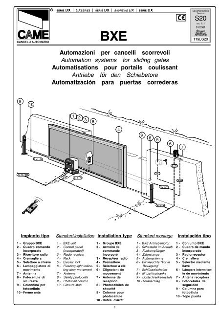
<strong>Automazioni</strong> <strong>per</strong> <strong>cancelli</strong> <strong>scorrevoli</strong><br />
<strong>Automation</strong> <strong>systems</strong> <strong>for</strong> sliding gates<br />
Automatisations pour portails coulissant<br />
Antriebe für den Schiebetore<br />
Automatización para puertas correderas<br />
Documentazione<br />
Tecnica<br />
S20<br />
rev. 1.1<br />
01/2001<br />
© CAME<br />
CANCELLI<br />
AUTOMATICI<br />
119BS20<br />
9<br />
11 10<br />
1 2 3<br />
8<br />
54<br />
1 2<br />
9<br />
10<br />
98<br />
65<br />
6<br />
7<br />
2 x 1 - TX<br />
2 x 1.5<br />
3 x 1.5 / 230V<br />
4 x 1 - RX<br />
23 x 1<br />
RG58<br />
2 x 1 - TX<br />
4 x 1 - RX<br />
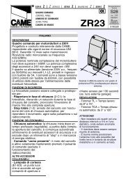
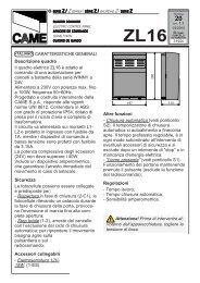
Impianto tipo Standard installation Installation type Standard montage Instalación tipo<br />
1 - Gruppo BXE<br />
2 - Quadro comando<br />
incorporato<br />
3 - Ricevitore radio<br />
4 - Cremagliera<br />
5 - Selettore a chiave<br />
6 - Lampeggiatore di<br />
movimento<br />
7 - Antenna<br />
8 - Fotocellule di<br />
sicurezza<br />
9 - Colonnina <strong>per</strong><br />
fotocellula<br />
10 - Fermo anta<br />
1 - BXE unit<br />
2 - Control panel<br />
(incorporated)<br />
3 - Radio receiver<br />
4 - Rack<br />
5 - Electric lock<br />
6 - Flashing light indicating<br />
door movement<br />
7 - Antenna<br />
8 - Safety photocells<br />
9 - Photocell column<br />
10 - Closure stop<br />
1 - Groupe BXE<br />
2 - Armoire de<br />
commande<br />
incorporé<br />
3 - Récepteur radio<br />
4 - Crémaillère<br />
5 - Sélecteur a clé<br />
6 - Clignotant de<br />
mouvement<br />
7 - Antenne de<br />
réception<br />
8 - Photocellules de<br />
sécurité<br />
9 - Colonne pour<br />
photocellule<br />
10 - Butée d'arrêt<br />
1<br />
1 - BXE Antriebsmotor<br />
2 - Schalttafel im Antrieb<br />
3 - Funkempfänger<br />
4 - Zahnstange<br />
5 - Außenantenne<br />
6 - Blinkleuchte “Tor in<br />
Bewegung”<br />
7 - Schlüsselschalter<br />
8 - IR Lichtschranke<br />
9 - Lichtschrankeensäule<br />
10 -Toranschlag<br />
1 - Conjunto BXE<br />
2 - Cuadro de mando<br />
incorporado<br />
3 - Radiorreceptor<br />
4 - Cremallera<br />
5 - Selector mediante<br />
llave<br />
6 - Lámpara intermitente<br />
de movimiento<br />
7 - Antena receptora<br />
8 - Fotocélulas de<br />
seguridad<br />
9 - Columna para<br />
fotocélula<br />
10 - Tope puerta
105<br />
310<br />
CARATTERISTICHE GENERALI - GENERAL SPECIFICATIONS - CARACTÉRISTIQUES GÉNÉRALES<br />
ALLGEMEINES - CARACTERÍSTICAS GENERALES<br />
Progettato e costruito<br />
interamente dalla CAME,<br />
risponde alle vigenti<br />
norme di sicurezza (UNI<br />
8612), con grado di protezione<br />
IP54.<br />
Garantito 12 mesi salvo<br />
manomissioni.<br />
Designed and constructed<br />
entirely by CAME;<br />
con<strong>for</strong>ms to (UNI 8612)<br />
safety standards with IP<br />
54 protection rating.<br />
12 mounth guarantee;<br />
guarantee void if unit is<br />
tam<strong>per</strong>ed with.<br />
Il a été entièrement<br />
conçu et realisé par les<br />
Ets CAME, con<strong>for</strong>mément<br />
aux normes de<br />
sécurité en vigueur<br />
(NFP 25362) avec degré<br />
de protection IP54.<br />
Il est garanti 12 mois<br />
sauf en cas d'endommagement.<br />
Vollständig von der CAME<br />
geplant und hergestellt,<br />
entsprechend den<br />
geltenden Sicherheitsbedigungen<br />
(UNI 8612)<br />
mit Schutzgrad IP54.<br />
12 Monate Garantie,<br />
Bedienungs - und Montagefehler<br />
ausgeschlossen.<br />
Diseñado y construido<br />
totalmente por CAME,<br />
con arreglo a las vigentes<br />
normas de seguridad<br />
(UNI 8612) con grado de<br />
protección IP54.<br />
Garantia de 12 meses<br />
salvo manipulaciones.<br />
Portata<br />
massima - Use<br />
limits - Portée max<br />
Torgewicht<br />
- Peso puerta<br />
uso residenziale<br />
Residential<br />
usage residentiel<br />
privaten einsatz<br />
uso residencial<br />
Kg 800<br />
CARATTERISTICHE TECNICHE - TECHNICAL CHARACTERISTICS - CARACTERISTIQUES TECHNIQUES<br />
TECNISCHE DATEN - CARACTERISTICAS TECNICAS<br />
MOTORIDUTTORE<br />
GEARMOTOR<br />
MOTORÉDUCTEUR<br />
GRADO DI<br />
PROTEZIONE<br />
PROTECTION<br />
RATING<br />
DEGRÉ DE<br />
PROTECTION<br />
GETRIEBEMOTOR SCHUTZGRAD GEWICHT<br />
MOTORREDUCTOR<br />
GRADO DE<br />
PROTECCION<br />
PESO ALIMENTAZIONE ASSORBIMENTO POTENZA<br />
INTERMITTENZA<br />
LAVORO<br />
WEIGHT POWER SUPPLY CURRENT POWER DUTY CICLE MAX TORQUE<br />
POIDS ALIMENTATION ABSORPTION PUISSANCE<br />
STROM_<br />
VERSORGUNG<br />
INTERMITTENCE<br />
DE TRAVAIL<br />
STROMAUFNAHME LEISTUNG EINSCHALTDAUER DREHMOMENT<br />
PESO ALIMENTACION ABSORBENCIA POTENCIA<br />
INTERMITENCIA<br />
TRABAJO<br />
COPPIA RAPPORTO DI RIDUZIONE SPINTA VELOCITA' MAX. CONDENSATORE<br />
REDUCTION<br />
RATIO<br />
PUSH MAX. SPEED CAPACITOR<br />
COUPLE RAPPORT DE REDUCTION POUSSÉE VITESSE MAX. CONDENSATEUR<br />
PAREJA<br />
(MOTOR)<br />
UNTERSETZUNGS_<br />
VERHÄLTNIS<br />
RELACION DE<br />
REDUCCION<br />
REGELBARER<br />
EMPUJE<br />
MAX.<br />
ÜBERTRAGUNGS<br />
VELOCIDAD<br />
MAX.<br />
KONDENSATOR<br />
CONDENSADOR<br />
BXE IP 54 15 Kg 230V a.c. 2,4A 300W 30 % * 32 Nm 1/33 800 N 10 m/min. 20 µF<br />
* Ottenuta mediante quadro comando CAME<br />
* Obtained with CAME control panel<br />
* Obtenue au moyen armoire de commande CAME<br />
* Erreicht mit Hilte der "CAME" Schalttafel<br />
* Se obtiene mediante el cuadro de mando CAME<br />
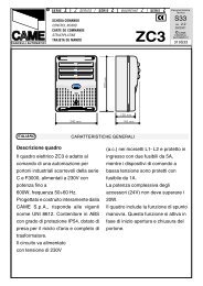
MISURE D'INGOMBRO - OVERALL DIMENSIONS - MESURES D'ENCOMBREMENT - ABMESSUNGEN - MEDIDAS<br />
240<br />
105<br />
22 max.<br />
165<br />
125<br />
290<br />
150<br />
2
PRIMA DELL'INSTALLAZIONE ... - BEFORE INSTALLING ..... - AVANT D'INSTALLER L'AUTOMATISME .....<br />
VOR DEN INSTALLATION ÜBERPRÜFEN ... - ANTES DE INSTALAR EL AUTOMATISMO...<br />
- Controllare che l'anta sia<br />
rigida e compatta e che le<br />
ruote di scorrimento<br />
siano in buono stato e<br />
adeguatamente ingrassate.<br />
- La guida a terra dovrà<br />
essere ben fissata al<br />
suolo, completamente in<br />
su<strong>per</strong>ficie in tutta la sua<br />
lunghezza e priva di<br />
irregolarità che possano<br />
ostacolare il movimento<br />
del cancello.<br />
- I pattini-guida su<strong>per</strong>iori<br />
non devono creare attriti.<br />
- Prevedere un fermo anta<br />
in a<strong>per</strong>tura e uno in<br />
chiusura ed il <strong>per</strong>corso<br />
dei cavi elettrici come da<br />
impianto tipo.<br />
- The gate must be sufficiently<br />
rigid and solid.<br />
- The wheels on which the<br />
gate slide must be in <strong>per</strong>fect<br />
condition and adequately<br />
lubricated.<br />
- The wheel guide must be<br />
firmly attached to the<br />
ground, completely exposed,<br />
and without any dips<br />
or irregular sections which<br />
might hinder the movement<br />
of the gate.<br />
- The up<strong>per</strong> guide must allow<br />
<strong>for</strong> the correct amount of<br />
play in order to guarantee<br />
smooth and silent movement<br />
of the gate.<br />
- Opening and closure stops<br />
must be installed.<br />
- The wiring must be routed<br />
as specified by the control<br />
and safety requirements.<br />
- Le panneau mobile du<br />
portail devra être suffisamment<br />
rigide et solide.<br />
- Les roues de coulissement<br />
devront être en<br />
très bon état. En outre,<br />
elles devront être convenablement<br />
graissées.<br />
- Le rail de guidage devra<br />
être bien fixé au sol. De<br />
plus, il devra se présenter<br />
entièrement en surface<br />
sans affaissement ou<br />
irrégularité (qui pourraient<br />
empêcher le<br />
mouvement du portail).<br />
- Le guide supérieur devra<br />
avoir un jeu convenable<br />
avec le portail (pour<br />
<strong>per</strong>mettre un mouvement<br />
régulier et silencieux).<br />
- Prévoir une butée d’arrêt<br />
à l’ouverture et à la<br />
fermeture.<br />
- Prévoir le passage des<br />
câbles électriques selon<br />
les dispositifs de commande<br />
et de sécurité.<br />
- Die Leistungfähigkeit der<br />
feststehenden und<br />
beweglichen Teile des Tores<br />
überprüfen.<br />
- Das Tor sollte ausreichend<br />
stabil sein. Die Gleitrollen<br />
sollten in guten Zustand<br />
und angemessen geschmiert<br />
sein.<br />
- Die Gleitführung auf dem<br />
Boden sollte sich in<br />
optimaler Position befinden:<br />
gut auf dem Boden<br />
befestigt, in seiner<br />
Gesamtlänge vollständig<br />
über dem Boden, ohne<br />
Vertiefungen und/oder<br />
Unebenheiten, die die<br />
Torbewegung behindern<br />
können.<br />
- Die oberen Führungsschienen<br />
sollten das<br />
richtige Spiel zum Tor<br />
haben, um ein präzises und<br />
regelmäßiges Gleiten zu<br />
garantieren.<br />
- Einen Anschlag für Tor Auf<br />
und Tor Tu sollte vorhanden<br />
sein.<br />
- Den Lauf der elektrischen<br />
Kabel nach den Steuerungs<br />
und Sicherheitsbestimmungen<br />
vorsehen.<br />
- La hoja de la puerta debe<br />
estar suficientemente rigida<br />
y compacta<br />
- Las ruedas de deslizamiento<br />
deben estar<br />
<strong>per</strong>fecta y engrasadas<br />
adecuadamente.<br />
- La guia de deslizamiento<br />
debe estar bien fijada en<br />
el suelo, sobresaliendo a<br />
lo largo de su entera<br />
longitud, sin huecos ni<br />
irregularidades (que<br />
podrian obstaculizar el<br />
movimiento de la puerta).<br />
- La guia su<strong>per</strong>ior debe tener<br />
el justo juego con la<br />
puerta metálica (para<br />
garantizar un movimiento<br />
regular y silencioso).<br />
- Disponer un tope para<br />
a<strong>per</strong>tura y el cierre.<br />
- Disponer un conducto<br />
para los cables eléctricos<br />
que cumpla con las<br />
disposiciones de mando<br />
y seguridad.<br />
FISSAGGIO BASE MOTORE - MOTOR TO BASE ANCHORAGE - FIXATION DE LA PLAQUE DU MOTEUR<br />
BEFESTIGUNGS DER MOTORBASIS - FIJACIÓN BASE MOTOR<br />
Anta cancello<br />
Gate wing<br />
Panneau mobile du portail<br />
Gleitachse<br />
Puerta<br />
Piastra di ancoraggio / Zanche<br />
Fixing plate / Anchor stays<br />
Plaque de fixation / Agrafes<br />
Gleitachse / Verankerung<br />
Placa de fijación / Barras de fijción<br />
50 mm.<br />
Cremagliera<br />
Rack-limit<br />
Cremaillére<br />
Zahnstange<br />
Cremallera<br />
75 mm.<br />
105 mm.<br />
Struttura fissa<br />
Wall<br />
Structrure fixe<br />
Feste Struktur<br />
Estructura fija<br />
Piazzola in cemento<br />
Concrete base<br />
Plate-<strong>for</strong>me en ciment<br />
Plattenachse<br />
Plata<strong>for</strong>ma de cemento<br />
Cavi<br />
Cable<br />
Câbles<br />
Kabel<br />
Cables<br />
- Inserire le viti nella piastra<br />
di ancoraggio bloccandole<br />
con i dadi in dotazione,<br />
ed estrarre le<br />
zanche pre<strong>for</strong>mate verso<br />
il basso.<br />
- Predisporre, dimensionandola<br />
in base alle<br />
misure del motoriduttore,<br />
una piazzola in cemento<br />
(si consiglia di farla<br />
sporgere dal terreno di<br />
circa 50 mm.) con<br />
annegata la piastra di<br />
ancoraggio e relative<br />
zanche sulla quale sara'<br />
fissato il gruppo.<br />
- La base di fissaggio<br />
dovra' risultare <strong>per</strong>fettamente<br />
in bolla, pulita in<br />
tutte le sue estremita',<br />
con il filetto delle viti<br />
completamente in<br />
su<strong>per</strong>fice.<br />
N.B.: Dalla stessa dovranno<br />
emergere i tubi flessibili<br />
<strong>per</strong> il passaggio dei cavi di<br />
collegamento elettrico.<br />
- Install the screws in the<br />
anchor plate and fasten<br />
them with a nut, then bend<br />
the pre-<strong>for</strong>med clamps<br />
downwards.<br />
- Construct a cement<br />
foundation that is large<br />
enough to accomodate the<br />
gear motor (it is a good idea<br />
to protrude 50 mm. from the<br />
ground). When pouring the<br />
foundation, embed the gear<br />
motor anchor plate and the<br />
relative clamps in the<br />
cement.<br />
- The anchor bolts should be<br />
embedded in the concrete<br />
in the positions indicated;<br />
the drive unit is then<br />
attached to this bots. The<br />
anchor plate must be<br />
<strong>per</strong>fectly level and absolutly<br />
clean; the bolts threads<br />
must be completly<br />
exposed.<br />
N.B.: The flexible tubes <strong>for</strong><br />
the electrical wiring must be<br />
embedded in the base and<br />
protude in the correct<br />
position.<br />
- Introduire les vis dans la<br />
plaque d'ancrage en les<br />
bloquant avec un écrou,<br />
et replier les agrafes<br />
pré<strong>for</strong>mées ver le bas.<br />
- Préparer une base en<br />
ciment d'une dimension<br />
adéquate aux mesures du<br />
motoréducteur (il est conseillé<br />
de la faire dépasser<br />
du terrain d'environ 50<br />
mm.), et noyer dedans la<br />
plaque d'ancrage et les<br />
agrafes correspondantes<br />
afin de <strong>per</strong>mettre le<br />
fixage du groupe.<br />
- La base de fixation devrà<br />
être parfaitement de<br />
niveau et propre sur toute<br />
sa surface et le filet des<br />
vis devra être complètement<br />
en surface.<br />
N.B. Les câbles pour le<br />
branchement électrique<br />
devront sortir de cette<br />
base.<br />
3<br />
- Die Schrauben in die<br />
Ankerplatte einfügen und<br />
mit einer Schraubenmutter<br />
blockieren, die vorge<strong>for</strong>mten<br />
Fundamentanker<br />
nach unten umbiegen.<br />
- Eine den Abmessungen<br />
des Getriebemotors entsprechende<br />
Betonfundamentplatte<br />
(Es empfiehlt<br />
sich, diese ca. 50 mm. vom<br />
Boden herausragen zu lassen)<br />
zum Einbetten der<br />
Ankerplatte und der entsprechenden<br />
Fundamentanker,<br />
die zur Befestigung<br />
des Antriebsaggregats<br />
dienen, vorbereiten.<br />
- Die Befestigungs-unterlage<br />
muß in seiner gesamten<br />
Länge vollkommen eben<br />
und sauber sein.<br />
Das Gewinde der Schrauben<br />
müssen gänzlich.<br />
hervorstehen.<br />
Wichtig: die Kabel für den<br />
Elektroanschluß müssen<br />
herausrgen.<br />
- Introducir los tornillos en<br />
la placa de anclaje,<br />
bloqueándolos con una<br />
tuerca, y doblar las<br />
palancas pre<strong>for</strong>madas<br />
hacia abajo.<br />
- Preparar, dándole las<br />
dimensiones adecuadas<br />
en función de las medidas<br />
del motorreductor,<br />
una plata<strong>for</strong>ma de cemento<br />
(se aconseja<br />
dejarla sobresalir del<br />
suelo aprox. 50 mm.) con<br />
la placa de enclaje<br />
embedida y con las<br />
correspondientes varillas,<br />
que <strong>per</strong>mitrá la<br />
fijación del grupo.<br />
- La base de fijación debe<br />
estar <strong>per</strong>fectamente<br />
nivelada, limpia en todos<br />
sus extremos, con la rosca<br />
de los tornillos totalmente<br />
in su<strong>per</strong>ficie.<br />
N.B.: De ésta deben<br />
sobresilar los tubos<br />
flexibles para el paso de<br />
los cables para las<br />
conexiones eléctricas.
INSTALLAZIONE DEL GRUPPO - UNIT INSTALLATION - INSTALATION DU GROUPE<br />
AUFSTELLUNG DES AGGREGATS - COLOCACIÓN DEL GRUPO<br />
Regolazione orizzontale e fissaggio<br />
Horizontal adjustment unit and achorage<br />
Réglage horizontal et fixation<br />
Horizontale Einstellung<br />
Regulación horizontal y fijación<br />
Accoppiamento pignone-cremagliera<br />
con gioco 1÷2 mm.<br />
Rack-to-pinion coupling with 1÷2 mm. clearance<br />
Assemblage pignon-crémailère avec jeu<br />
de 1 à 2 mm.<br />
Zwischen Zahnstange und dem Antriebsritzel<br />
1÷2 mm. Spiel einstellen<br />
Acoplamiento piñon-cremaliera<br />
1÷2 mm. de juego<br />
1÷2 mm.<br />
Regolazione verticale - messa in bolla<br />
Vertical adjustment and unit leveling<br />
Réglage vertical - mise à niveau<br />
Vertikale Einstellung<br />
Regulación vertical y nivelación<br />
Ingresso cavi<br />
Cable entrances<br />
Passage des câbles<br />
Kabeleinführungen<br />
Entrada cables<br />
5÷10 mm.<br />
Nella fase preliminare di<br />
installazione, i piedini<br />
dovranno sporgere di 5-<br />
10 mm. <strong>per</strong> <strong>per</strong>mettere<br />
allineamenti, fissaggio<br />
della crema-gliera e<br />
regolazioni successive.<br />
L'accoppiamento esatto<br />
con la linea di scorrimento<br />
del cancello è<br />
ottenibile dal sistema di<br />
regolazione integrale<br />
(brevettato) composto<br />
da:<br />
- le asole che <strong>per</strong>mettono<br />
la regolazione<br />
orizzontale;<br />
- i piedini filettati in<br />
acciaio che <strong>per</strong>mettono<br />
la regolazione<br />
verticale e la messa in<br />
bolla;<br />
- le piastrine e i dadi di<br />
fissaggio che rendono<br />
solidale l'aggancio del<br />
gruppo alla base.<br />
During the initial phase of<br />
installation, the feet should<br />
protrude by 5-10 mm. in<br />
order to allow <strong>for</strong><br />
alignment, anchorage of<br />
the rack and further<br />
adjustments.<br />
Perfect alignment with the<br />
guide rail is made possible<br />
by the (patented) built-in<br />
regulation system, which<br />
consists of:<br />
- slots <strong>for</strong> horizontal<br />
adjustment;<br />
- threaded steel feet <strong>for</strong><br />
vertical adjustment and<br />
levelling;<br />
- plates and bolts <strong>for</strong><br />
anchorage to the base.<br />
Dans la phase de<br />
instalation préliminaire,<br />
les broches devront<br />
dépasser de 5 à 10 mm<br />
afin de <strong>per</strong>mettre les<br />
alignements et les<br />
réglages nécessaires<br />
après la pose.<br />
L’accouplement exact<br />
avec la ligne de<br />
coulissement du portail<br />
s’effectue par le<br />
système de réglage<br />
hauteur (breveté) dont<br />
le groupe est pourvu, et<br />
qui comprend plus<br />
précisément:<br />
- les trous oblong<br />
<strong>per</strong>mettant le réglage<br />
horizontal;<br />
- les broches filetées en<br />
acier qui donnent le<br />
réglage vertical et la<br />
mise à niveau;<br />
- les plaques et les<br />
écrous de fixation qui<br />
assemblent solidement<br />
le groupe à la<br />
plaque de fixation<br />
scellée.<br />
Nun die Montage des<br />
Antriebsmotors vornehmen.<br />
Die genaue Kopplung<br />
mit der Gleitlinie des<br />
Tors wird von dem<br />
integrierten Einstellungssystem<br />
(patentiert)<br />
garantiert, mit dem das<br />
Aggregat ausgestattet ist<br />
und zwar:<br />
- die Osen für die<br />
horizontale Einstellung,<br />
- die Gewindefüße aus<br />
Stahl für die vertikale<br />
Einstellung und die<br />
Nivellierung,<br />
- die Befestigungsplättchen<br />
und muttern zur<br />
soliden Befestigung des<br />
Aggregats an die<br />
Bodenplatte.<br />
Während der Vorbereitungsarbeiten<br />
der<br />
Montage sollten die<br />
Füße 5-10 mm herausragen,<br />
um Ausfluchtungen<br />
und Einstellung<br />
auch nach der Fertigstellung<br />
zu ermöglich.<br />
En la fase previa de la<br />
colocación, los pies<br />
deben sobresalir 5-10<br />
mm para consentir la<br />
alineación, la fijación de<br />
la cremallera y las regulaciones<br />
sucesivas.<br />
El acoplamiento exacto<br />
con la linea de deslizamiento<br />
de la puerta<br />
metálica se obtiene mediante<br />
el sistema de<br />
regulación integral<br />
(patentado) que consta<br />
de:<br />
- los agujeros ovalados<br />
que consienten la<br />
regulación horizontal;<br />
- las tuercas de acero<br />
que <strong>per</strong>miten la<br />
regulación vertical y la<br />
nivelación;<br />
- las placas y las tuercas<br />
de fijación que hacen<br />
solidario el enganche<br />
del conjunto con la<br />
base.<br />
4
FISSAGGIO CREMAGLIERA- ATTACHING THE RACK/LIMIT - FIXATION CREMAILLÉRE<br />
MONTAGE DE ZAHNSTANGE - FIJACIÓN DE LA CREMALLERA<br />
Al fine di <strong>per</strong>mettere<br />
all'ENCODER di rilevare<br />
la corsa del cancello,<br />
fissare la cremagliera<br />
con il cancello a meta'<br />
corsa:<br />
Install the rack with the<br />
gate at the half-way point.<br />
This will enable the<br />
ENCODER to detect<br />
gate travel pro<strong>per</strong>ly:<br />
Afin de <strong>per</strong>mettre à<br />
l'ENCODEUR de relever<br />
la course du portail,<br />
fixer la crémaillère avec<br />
le portail à mi-course:<br />
Ist der ENCODER zur<br />
Erfassung bzw. Überwachung<br />
des Torlaufs auf<br />
halber Laufhöhe auf der<br />
Zahnstange zu befestigen:<br />
Con el fin de <strong>per</strong>mitir al<br />
ENCODER medir la<br />
carrera de la puerta, fijar<br />
la cremallera con el<br />
mismo a mitad de<br />
carrera:<br />
- portare l'anta a meta'<br />
corsa, appoggiare la<br />
cremagliera sul<br />
pignone del motoriduttore<br />
e far scorrere<br />
manualmente il cancello<br />
fissando la<br />
cremagliera in tutta la<br />
sua lunghezza;<br />
- La corsa massima del<br />
cancello é di 14 m;<br />
- ultimata l'o<strong>per</strong>azione<br />
di fissaggio della<br />
cremagliera, regolare i<br />
piedini (servendosi di<br />
un cacciavite) in modo<br />
da ottenere il giusto<br />
giuoco tra pignone e<br />
cremagliera (1-2 mm).<br />
N.B. : Questo evitera'<br />
che il peso del cancello<br />
vada a gravare sul<br />
gruppo.<br />
- Se la cremagliera é gia'<br />
fissata, procedere<br />
direttamente alla regolazione<br />
dell'accoppiamento<br />
pignonecremagliera.<br />
- Eseguite tutte le<br />
regolazioni, fissare il<br />
gruppo stringendo i<br />
dadi di fissaggio.<br />
- allow the door to reach<br />
mid-run, set the rack on<br />
the rationmotor's pinion<br />
and slide the gate<br />
manually, fixing the<br />
rack's entire lenght;<br />
- The gate's maximum run<br />
is 14 m;<br />
- when the rack is attached<br />
to the gate, adjust the<br />
feet using a screwdriver<br />
until the play between<br />
the pinion and the rack is<br />
correct (1-2 mm.).<br />
N.B.: This position<br />
ensures that the weight of<br />
the gate does not rest on<br />
the gearmotor.<br />
- If the rack is already<br />
attached, proceed<br />
directly to the adjustment<br />
of the rack/pinion<br />
coupling.<br />
- When the necessary<br />
adjustment have been<br />
completed, fasten the<br />
unit in position by<br />
tightening the two anchor<br />
bolts.<br />
- mettre la porte à la<br />
moitié de sa course,<br />
poser la crémaillère<br />
sur le pignon du<br />
motoréducteur et faire<br />
coulisser manuellement<br />
le portail en<br />
fixant la crémaillère sur<br />
toute sa longueur;<br />
- La course maximum du<br />
portail est de 14 m;<br />
- Lorsque la fixation de<br />
la crémaillère est<br />
terminée régler les<br />
broches (en utilisant<br />
un tournevis) de façon<br />
à obtenir un jeu<br />
convenable (1-2 mm)<br />
dans l’assemblage du<br />
pignon et de la<br />
crémaillère.<br />
N.B. Ceci pour éviter<br />
que le poids du portail<br />
ne repose sur le groupe.<br />
- Si la crémaillère est<br />
déjà fixée, utiliser le<br />
système de réglage<br />
hauteur pour assembler<br />
correctement de<br />
facon exacte le pignon<br />
et la crémaillère.<br />
- Exécuter tous les<br />
réglages, fixer le<br />
groupe en serrant les<br />
deux écrous de<br />
fixation.<br />
- den Torflügel halb öffnen<br />
und die Zahnstange auf<br />
dem Ritzel vom<br />
Getriebe-motor auflegen.<br />
Dann das Tor von<br />
Hand verschieben und<br />
dabei die Zahnstange<br />
auf ganzer Länge<br />
befestigen;<br />
- Der maximale Lauf vom<br />
Tor beträgt 14 m;<br />
- Die verstellbaren Füße<br />
des Antriebsmotors (mit<br />
einem Schraubenzieher)<br />
so einstellen,<br />
daß zwischen Ritzel und<br />
Zahnstange ein Spiel (1-<br />
2 mm) besteht.<br />
Wichtig: Dadurch wird<br />
vermieden, daß das<br />
Gewicht des Tores auf<br />
dem Aggregat lastet.<br />
- Nach diesen Einstellungsarbeiten<br />
das<br />
Aggregat durch Anziehen<br />
der beiden Muttem<br />
befestigen.<br />
- coloque la hoja en la<br />
mitad de la carrera,<br />
apoye la cremallera<br />
sobre el piñon del<br />
motorreductor y<br />
deslice manualmente<br />
la puerta, fijando la<br />
cremallera a todo lo<br />
largo;<br />
- La carrera máxima de<br />
la puerta es de 14 m;<br />
- Finalizadas las o<strong>per</strong>aciones<br />
para la<br />
fijacion de la cremallera,<br />
regular los pies<br />
(por medio de un<br />
destornillador) de<br />
modo que se obtenga<br />
el justo juego entre el<br />
piñón y la cremallera<br />
(1-2 mm).<br />
N.B. Esto hace que el<br />
peso de la puerta<br />
metálica no cargue<br />
sobre el conjunto.<br />
- Si la cremallera ya ha<br />
sido fijada, hay que<br />
regular el acoplamiento<br />
piñón-cremallera.<br />
- Una vez realizados los<br />
ajuste, fijar el conjunto<br />
cerrando las dos<br />
tuercas de fijación.<br />
5
SBLOCCO MOTORIDUTTORE - GEAR RELEASE - OPÉRATION DE DÉBLOCAGE - ANTRIEBSENTRIEGELUNG<br />
DESBLOQUEO MOTORREDUCTOR<br />
Per aprire lo sportellino<br />
inserire la chiave,<br />
spingerla e ruotala in<br />
senso orario; sbloccare<br />
quindi il motoriduttore<br />
ruotando la manopola<br />
nella direzione indicata.<br />
To open the access door,<br />
insert the key, push down<br />
and rotate clockwise.<br />
Now, release the gear<br />
motor by rotating the knob<br />
in the direction shown.<br />
Pour ouvrir la trappe,<br />
introduire la clé, la<br />
pousser et la tourner<br />
dans le sens des<br />
aiguilles d'une montre.<br />
Débloquer ensuite le<br />
motoréducteur en<br />
tournant la poignée<br />
dans la direction<br />
indiquée.<br />
Zum Öffnen der klappe<br />
den Schlüssel einfügen,<br />
hineindrücken und im<br />
Uhrzeigersinn drehen.<br />
Dann den Getriebemotor<br />
durch Drehen des Knopfs<br />
in die angegebene<br />
Richtung ents<strong>per</strong>ren.<br />
Para abrir la portezuela<br />
introducir la llave,<br />
empujarla y girarla en<br />
sentido horario;<br />
desbloqear el motorreductor<br />
girando la<br />
manilla en la dirección<br />
indicada.<br />
ATTENZIONE:<br />
l'a<strong>per</strong>tura dello sportellino<br />
di sblocco impedisce<br />
il funzionamento del<br />
motore.<br />
ATTENTION:<br />
the opening of the unblock<br />
panel arrests the motor.<br />
ATTENTION:<br />
l’ouverture de la porte<br />
de déblocage empêche<br />
le fonctionnement du<br />
moteur.<br />
ACHTUNG:<br />
Wenn das Freigabetürchen<br />
geöffnet wird,<br />
funktioniert der Motor<br />
nicht.<br />
ATENCIÓN:<br />
la a<strong>per</strong>tura de la tapa de<br />
desbloqueo, impide el<br />
funcionamiento del<br />
motor.<br />
CAME<br />
Blocco<br />
Engage<br />
Blocage<br />
Blockierend<br />
Bloqueo<br />
Sblocco<br />
Release<br />
Déblocage<br />
Entriegelt<br />
Desbloqueo<br />
6
ITALIANO<br />
DESCRIZIONE TECNICA SCHEDA BASE ZBXE<br />
La scheda comando va alimentata a (230V<br />
a.c.) sui morsetti L1 e L2 ed è protetto in<br />
ingresso con fusibili da 5A e varistore V1.<br />
I dispositivi di comandi sono a bassa tensione<br />
(24V), e sono protetti con fusibile da 1A<br />
e varistori V2. La potenza complessiva degli<br />
accessori a 24V, non deve su<strong>per</strong>are i<br />
20W.<br />
Il tempo lavoro è fisso a 90 secondi.<br />
SICUREZZA<br />
Le fotocellule possono essere collegate e<br />
predisposte <strong>per</strong>:<br />
- Ria<strong>per</strong>tura in fase di chiusura (2-C1);<br />
- Stop parziale, arresto del cancello se in<br />
movimento con conseguente predisposizione<br />
alla chiusura automatica<br />
(2-C3);<br />
- Stop totale, (1-2) arresta il cancello escludendo<br />
l'eventuale ciclo di chiusura<br />
automatica; <strong>per</strong> riprendere il movimento bisogna<br />
agire sulla pulsantiera o sul<br />
radiocomando;<br />
Nota: Se un contatto di sicurezza normalmente<br />
chiuso (2-C1, 2-C3, 1-2) si apre,<br />
viene segnalato dal lampeggio del LED di<br />
segnalazione (n°11)<br />
- Rilevazione di presenza ostacolo. A motore<br />
fermo (cancello chiuso, a<strong>per</strong>to o dopo un<br />
comando di stop totale), impedisce qualsiasi<br />
movimento se i dispositivi di sicurezza<br />
(es.fotocellule) rilevano un ostacolo.<br />
- La scheda, inoltre, integra e gestisce automaticamente<br />
una funzione di sicurezza che,<br />
in caso di rilevazione di ostacoli, funziona<br />
nel seguente modo:<br />
in a<strong>per</strong>tura<br />
il cancello inverte il senso di marcia fino alla<br />
completa a<strong>per</strong>tura;<br />
in chiusura<br />
il cancello inverte il senso di marcia fino alla<br />
completa a<strong>per</strong>tura con conseguente intervento<br />
della chiusura automatica.<br />
Attenzione! dopo tre inversioni consecutive,<br />
il cancello resta a<strong>per</strong>to escludendo la<br />
chiusura automatica: <strong>per</strong> chiudere, usare il<br />
radiocomando o il pulsante di chiusura.<br />
ACCESSORI COLLEGABILI<br />
-Lampada ciclo. Lampada che illumina la<br />
zona di manovra, rimane accesa dal momento<br />
in cui l'anta inizia l'a<strong>per</strong>tura fino alla<br />
completa chiusura (compreso il tempo di<br />
chiusura automatica). La funzione della lampada<br />
ciclo si ottiene in uscita W-E1 solo se<br />
i dip n°9 «chiusura automatica» e n°8<br />
«rilevazione di presenza ostacolo» sono<br />
posizionati in ON, vedi pagina 12;<br />
-Lampada spia cancello a<strong>per</strong>to. Lampada<br />
che segnala la posizione di a<strong>per</strong>tura del<br />
cancello e che si spegne quando il cancello<br />
attiva il finecorsa chiude; collegarla ai<br />
morsetti 10-5.<br />
Nota: gli accessori a 24V non necessitano<br />
di collegamento a terra.<br />
ALTRE FUNZIONI<br />
- Chiusura automatica. Il temporizzatore di<br />
chiusura automatica si autoalimenta a<br />
finecorsa in a<strong>per</strong>tura. Il tempo prefissato<br />
regolabile, é comunque subordinato dall'intervento<br />
di eventuali accessori di sicurezza<br />
e si esclude dopo un intervento di «stop»<br />
totale o in mancanza di energia elettrica;<br />
- A<strong>per</strong>tura parziale. A<strong>per</strong>tura del cancello<br />
<strong>per</strong> passaggio pedonale, viene attivata collegandosi<br />
ai morsetti 2-3P ed è regolabile<br />
mediante trimmer AP.PARZ.;<br />
-Funzionamento a uomo presente. Funzionamento<br />
del cancello mantenendo premuto<br />
il pulsante (selezionandolo si esclude la<br />
funzione del radiocomando);<br />
- Programmazione taratura dei finecorsa<br />
elettronici di a<strong>per</strong>tura e di chiusura;<br />
- Funzione master, il quadro assume tutte le<br />
funzioni di comando nel caso di due motori<br />
abbinati (vedi pagina 15);<br />
- Prelampeggio in a<strong>per</strong>tura e chiusura;<br />
-Tipo di comando:<br />
- apre-chiude-inversione;<br />
- apre-stop-chiude-stop;<br />
- solo a<strong>per</strong>tura.<br />
Regolazioni<br />
- Trimmer AP.PARZ. = A<strong>per</strong>tura parziale:<br />
da 4"a 15";<br />
- Trimmer TCA = Tempo chiusura automatica:<br />
da 1" a 160";<br />
Attenzione:<br />
- l'a<strong>per</strong>tura dello sportellino di sblocco impedisce<br />
il funzionamento del motore.<br />
- prima di intervenire all'interno dell'apparecchiatura,<br />
togliere la tensione di linea e<br />
scollegare le batterie (se inserite).<br />
ENGLISH<br />
TECHNICAL DESCRIPTION ZBXE MOTHERBOARD<br />
This control board is powered by 230V AC<br />
across terminals L1 and L2, and is protected<br />
by a 5A fuse on the main power line with<br />
varistor V1. Control <strong>systems</strong> are powered<br />
by low voltage and protected with by a 1A<br />
fuse with varistor V2.<br />
The total power consumption of 24 V<br />
accessories must not exceed 20 W.<br />
Fixed o<strong>per</strong>ating time of 90 seconds.<br />
SAFETY<br />
Photocells can be connected to obtain:<br />
- Re-opening during the closing cycle (2-<br />
C1);<br />
- Partial stop, shutdown of moving gate, with<br />
activation of an automatic closing cycle (2-<br />
C3);<br />
- Total stop, (1-2) shutdown of gate<br />
movement without automatic closing; a<br />
pushbutton or radio remote control must be<br />
actuated to resume movement;<br />
Note: If a safety contact which is normally<br />
closed (2-C1, 2-C3, 1-2) is opened, the LED<br />
(n°11) will flash to indicate this fact;<br />
- Obstacle presence detection. When the<br />
motor is stopped (gate is closed, open or<br />
half-open after an emercency stop<br />
command), the transmitter and the control<br />
pushbutton will be deactivated if an obstacle<br />
is detected by one of the safety devices (<strong>for</strong><br />
example, the photocells).<br />
- In addition, the board automatically<br />
integrates and runs a safety function that<br />
works in the following manner in case<br />
obstacles are detected;<br />
during opening<br />
the gate inverts the movement direction until<br />
it is completely close;<br />
during closure<br />
the gate inverts its direction until it is<br />
completely open, after which it closes<br />
automatically.<br />
Warning! after three consecutive inversions,<br />
the gate will remain open and automatic<br />
closure will be discontinued. Toclose the<br />
gate, use the radio remote control or the<br />
push-button.<br />
ACCESSORIES WHICH CAN BE<br />
CONNECTED<br />
- Cycle lamp. The lamp which lights the<br />
manoeuvring zone: it remains lit from the<br />
moment the gate begin to open until it is<br />
completely closed (including the time<br />
required <strong>for</strong> the automatic closure). The<br />
function of the cycle lamp is obtained in<br />
output W-E1 only if dip switch numbers: No.9<br />
«automatic closing» and No.8 «detect<br />
obstacle presence» are set to ON (see<br />
page 12).<br />
- Open gate pilot lamp. It is a light that indicates<br />
the sliding gate's open position and<br />
turns off when the gate activates the closing<br />
end-stop, connect it to terminal blocks 10-5.<br />
N.B.: the 24V accessories do not need a<br />
earth connection.<br />
OTHER FUNCTIONS<br />
- Automatic closing. The automatic closing<br />
timer is automatically activated at the end<br />
of the opening cycle. The preset, adjustable<br />
7<br />
automatic closing time is automatically<br />
interrupted by the activation of any safety<br />
system, and is deactivated after a STOP<br />
command or in case of power failure;<br />
- Partial opening. Gate opening <strong>for</strong> passage<br />
on foot is activated by connecting to the 2-<br />
3P terminal blocks and it can be adjusted<br />
by the AP.PARZ. trimmer;<br />
- "O<strong>per</strong>ator present" function: Gate o<strong>per</strong>ates<br />
only when the pushbutton is held down (radio<br />
remote control is deactivated when<br />
function is selected);<br />
- Programming the calibration of the<br />
electronic opening and closing limit<br />
switches;<br />
- Master function; the panel assumes all the<br />
command functions when two paired<br />
motors are used (see pag. 15);<br />
- Flashing light activated be<strong>for</strong>e opening and<br />
closing cycle begins;<br />
- Selection of command sequence:<br />
-open-close-reverse;<br />
-open-stop-close-stop;<br />
-open only<br />
ADJUSTMENTS<br />
-Trimmer AP.PARZ. = Partial opening: 4" to<br />
15";<br />
-Trimmer TCA = Automatic closing time: 1"<br />
to 160";<br />
Important:<br />
- the opening of the unblock panel arrests<br />
the motor.<br />
- Shut off the mains power and disconnect<br />
the batteries be<strong>for</strong>e servicing the inside of<br />
the unit.
ZBXE<br />
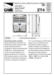
SCHEDA BASE ZBXE - ZBXE MOTHERBOARD - CARTE BASE ZBXE - GRUNDPLATINE ZBXE - TARJETA BASE ZBXE<br />
2<br />
1<br />
3<br />
ENCODER<br />
AF<br />
13<br />
4<br />
5<br />
CHIUDE<br />
11<br />
10<br />
O<br />
N<br />
7<br />
1 2 3 4 5 6 7 8 9 10<br />
CH1<br />
6<br />
CH2<br />
12<br />
APRE<br />
8<br />
9<br />
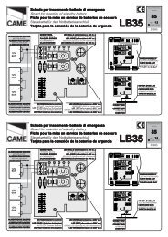
COMPONENTI PRINCIPALI<br />
1 Morsettiere di collegamento<br />
2 Fusibili di linea 5A e varistore 420V<br />
3 Fusibile accessori 1A e 6 varistori 60V<br />
4 Innesto scheda radiofrequenza (vedi tabella)<br />
5 LED di segnalazione codice radio<br />
6 Pulsanti memorizzazione codice radio<br />
7 Dip-switch "selezione funzioni"<br />
8 Trimmer AP.PARZ.: regolazione a<strong>per</strong>tura parziale<br />
9 Trimmer TCA: regolazione tempo di chiusura automatica<br />
10 LED di segnalazione chiusura automatica e<br />
prog.encoder<br />
11 Pulsante programmazione finecorsa chiude<br />
12 Pulsante programmazione finecorsa apre<br />
13 Scheda fissa Encoder<br />
I<br />
MAIN COMPONENTS<br />
1 Terminal block <strong>for</strong> external connections<br />
2 5A line fuse and varistor 420V<br />
3 1A accessories fuse and 6 varistors 60V<br />
4 Socket radiofrequency board (see table)<br />
5 Radio code signal LED<br />
6 Buttons <strong>for</strong> storing radio code numbers<br />
7 "Function selection" dip-switch<br />
8 Trimmer AP.PARZ.: Partial opening adjustment<br />
9 Trimmer TCA: automatic closing time adjustment<br />
10 Automatic closing and program encoder signal LED<br />
11 Closing limit switch programming button<br />
12 Opening limit switch programming button<br />
13 Encoder mother board<br />
HAUPTKOMPONENTEN<br />
GB<br />
1 Anschluss-Klemmenleiste<br />
2 5A-Sicherung Leitungs und varistor 420V<br />
3 1A-Sicherung Zubehörs und 6 varistor 60V<br />
4 Steckanschluß Funkfrequenze-Platine (sehen Tabelle)<br />
5 Anzeige-LED Funkcode<br />
6 Funkcode-Speichertasten<br />
7 "Funktionswahl" dip-switch<br />
8 Trimmer AP.PARZ.: Einstellung Teilöffnung<br />
9 Trimmer TCA: Einstellung Zeiteinstellung<br />
Schließautomatik<br />
10 Anzeige-LED Schließautomatik und Programmier encoder<br />
11 Endausschalter Schließen-Programmiertaste<br />
12 Endausschalter Öffnen-Programmiertaste<br />
13 feste Encoder-Platine<br />
D<br />
COMPOSANTS PRINCIPAUX<br />
1 Plaque à bornes pour les branchements<br />
2 Fusibles de ligne 5A et varistance 420V<br />
3 Fusible accessoires 1A et 6 varistance 60V<br />
4 Branchement carte radiofréquence (voir tableau)<br />
5 LED de signalisation code radio<br />
6 Boutons-poussoirs mémorisation codes code radio<br />
7 Dip-switch "sélection fonction"<br />
8 Trimmer AP.PARZ.: Réglage Ouverture partielle<br />
9 Trimmer TCA: Réglage Temps de fermeture<br />
automatique<br />
10 LED de signalisation fermeture automatique et<br />
prog.encoder<br />
11 Bouton-poussoir programmation fin de course<br />
fermeture<br />
12 Bouton-poussoir programmation fin de course ouverture<br />
13 Carte fixe Encodeur<br />
COMPONENTES PRINCIPALES<br />
1 Caja de bornes para las conexiónes<br />
2 Fusible de linea 5A y varistor 420V<br />
3 Fusible accesorios 5A y 6 varistor 60V<br />
4 Conexión tarjeta radiofrecuencia (ver tabla)<br />
5 LED de señal código radio<br />
6 Teclas memorización código radio<br />
7 Dip-switch "seleción función"<br />
8 Trimmer AP.PARZ.: Regulación A<strong>per</strong>tura parcial<br />
9 Trimmer TCA: Regulación cierre automático<br />
10 LED de señal cierre automático y programación<br />
encoder<br />
11 Tecla programación final de carrera cierre<br />
12 Tecla programación final de carrera abierta<br />
13 Tarjeta fija Encoder<br />
F<br />
E<br />
10
ZBXE<br />
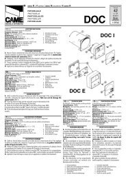
COLLEGAMENTI ELETTRICI - ELECTRICAL CONNECTIONS - BRANCHEMENTS ÉLECTRIQUES - ELEKRISCHE ANSCHLÜSSE - CONEXIONES ELÉCTRICAS<br />
L1 L2 0 220 CT 0 12 24 U V W E1 10 11 1 2 3 3P 4 5 7<br />
_<br />
2MOT + E 2 C1C3 B1 B2<br />
L1<br />
L2<br />
Alimentazione 230V (a.c.)<br />
230V (a.c.) power input<br />
Alimentation 230V (c.a.)<br />
Stromversorgung 230V (Wechselstrom)<br />
Alimentación 230V (a.c.)<br />
U<br />
W<br />
V<br />
Motore monofase 230V(a.c.)<br />
230V (a.c.) single-phase motor<br />
Moteur monophasé 230V (c.a.)<br />
Einphasenmotor 230V (Wechselstrom)<br />
Motor monofásico 230V (a.c.)<br />
Uscita 230V (a.c.) in movimento (es.lampeggiatore - max. 25W)<br />
230V (a.c.) output in motion (e.g. flashing light - MAX. 25W)<br />
Sortie 230V (c.a.) en mouvement (ex. branchement clignotant max. 25)<br />
Ausgang 230V (Wechselstrom) in Bewegung (z.B. Blinker-Anschluß - max.25W)<br />
Salida de 230V (a.c.) en movimento (p.ej. conexión lámpara intermitente<br />
max. 25W)<br />
W<br />
E1<br />
Uscita 230V (a.c.) lampada ciclo - max. 60W (vedi descrizione pag. 7)<br />
230V (a.c.) max. 60W -cycle lamp (see description pg. 7)<br />
Sortie 230V (c.a.) lampe cycle - max. 60W (voir description pag. 7)<br />
Betriebszyklus-Anzeigeleuchte - 230V (Wechselstrom) - max.60W (sehen S. 7)<br />
Salida de 230V (a.c.) lámpara ciclo - max. 60W (mirar descripción pág. 7)<br />
ON<br />
U V<br />
W E1<br />
1 2 3 4 5 6 7 8 9 10<br />
U V W E1<br />
10<br />
11<br />
1<br />
2<br />
2<br />
3<br />
Alimentazione accessori 24V (a.c.) max. 20W<br />
24V (a.c.) Powering accessories (max 20W)<br />
Alimentation accessoires 24V (a.c.) max.20W<br />
Zubehörspeisung 24V (Wechselstrom) max. 20W<br />
Alimentación accesorios 24V (a.c.) max. 20W<br />
Pulsante stop (N.C.)<br />
Pushbutton stop (N.C.)<br />
Bouton-poussoir arrêt (N.F.)<br />
Stop-Taste (N.C.)<br />
Pulsador de stop (N.C.)<br />
Pulsante apre (N.O.)<br />
Pushbutton open (N.O.)<br />
Bouton-possoir ouverture (N.O.)<br />
Taste Öffnen (N.O.)<br />
Pulsador de a<strong>per</strong>tura (N.O.)<br />
N.B. Rispettare la polarità nel<br />
collegamento delle fotocellule (TX e<br />
RX).<br />
N.B. When connecting the photocells<br />
(TX and RX), observe the correct<br />
polarities.<br />
N.B. Respecter la polarité lors de la<br />
connexion des photocellules (TX et<br />
RX).<br />
Anmerkung: beim Anschließen der<br />
Photozellen (TX und RX) auf die<br />
Polung achten.<br />
N.B. Respetar la polaridad en la<br />
conexión de las fotocélulas (TX y<br />
RX).<br />
TX RX<br />
10 11<br />
NO C NC<br />
2<br />
3P<br />
Pulsante apre (N.O.) <strong>per</strong> a<strong>per</strong>tura parziale<br />
Open button (N.O.) <strong>for</strong> partial opening<br />
Bouton-poussoir d'ouverture (N.O.) pour ouverture partial<br />
Taste Öffnen (Arbeitskontakt) für Partial-Stop<br />
Pulsador de a<strong>per</strong>tura (N.O.) para a<strong>per</strong>tura parcial<br />
11
ZBXE<br />
COLLEGAMENTI ELETTRICI - ELECTRICAL CONNECTIONS - BRANCHEMENTS ÉLECTRIQUES - ELEKRISCHE ANSCHLÜSSE - CONEXIONES ELÉCTRICAS<br />
Terra<br />
Ground<br />
Terre<br />
Erde<br />
Tierra<br />
2<br />
4<br />
Pulsante chiude (N.O.)<br />
Close button (N.O.)<br />
Poussoir de fermeture (N.O.)<br />
Taste Schließen (Arbeitskontakt)<br />
Pulsador de cierre (N.O.)<br />
2<br />
7<br />
Contatto radio e/o pulsante <strong>per</strong> comando (vedi dip-switch 2-3-4 sel.funzioni)<br />
Contact radio and/or button <strong>for</strong> control (see dip-switch 2-3-4function selection)<br />
Contact radio et/ou poussoir pour commande (dip-switch 2-3-4 sel.fonction)<br />
Funkkontakt und/oder Taste Steuerart (dip-switch 2-3-4 Funktionswahl)<br />
Contacto radio y/o pulsador para mando (dip-switch 2-3-4 sel.fonción)<br />
2<br />
C1<br />
Contatto (N.C.) di «ria<strong>per</strong>tura durante la chiusura»<br />
Contact (N.C.) <strong>for</strong> «re-a<strong>per</strong>ture during closure»<br />
Contact (N.F.) de «réouverture pendant la fermeture»<br />
Kontakt (Ruhekontakt) Wiederöffnen beim Schliessen<br />
Contacto (N.C.) para la a<strong>per</strong>tura en la fase de cierre<br />
2<br />
C3<br />
Contatto (N.C.) stop parziale<br />
Partial stop contact (N.C.)<br />
Contact (N.F.) d'arrêt partial<br />
Teil-Stop (Ruhekontakt) Kontakt<br />
Contacto (N.C.) de stop parcial<br />
10<br />
5<br />
Lampada spia (24V-3W) cancello a<strong>per</strong>to<br />
24V-3W gate-opened signal lamp<br />
Lampe-témoin (24V-3W) portail ouverture<br />
Signallampe (24V-3W), Öffnen<br />
Lampara indicadora (24V-3W) puerta abierta<br />
Collegamento antenna<br />
Antenna connection<br />
Connexion antenne<br />
Antennenanschluß<br />
Conexión antena<br />
B1<br />
B2<br />
Uscita contatto (N.O.) Portata contatto: 5A a 24V(d.c.)<br />
Contact output (N.O.) Resistive load: 5A 24V (d.c.)<br />
Sortie contact (N.O.) Portée contact: 5A a 24V(c.c.)<br />
Ausgang Arbeitskontakt Stromfestigkeit: 5A bei 24V (Gleichstrom)<br />
Salida contacto (N.O.) Carga resistiva: 5A a 24V (d.c.)<br />
2MOT<br />
Uscita <strong>per</strong> comando simultaneo di n.2 motori abbinati<br />
Connection <strong>for</strong> simultaneous control of 2 combined motors<br />
Sortie pour commande simultanée de 2 moteurs accouples<br />
Ausgang zur gleichzeitigen Steuerung von 2 parallelgeschalteten Motoren<br />
Salida para el mando simultáneo de n.2 motores acoplados<br />
12
COLLEGAMENTO A TERRA / EARTH CONNECTION / BRANCHEMENT Á LA TERRE<br />
ERDUNG / CONEXIÓN A TIERRA<br />
Collegare il filo di terra usando la vite<br />
automaschiante (A) in dotazione.<br />
(A)<br />
Connect the earth wire by using the provided<br />
self-tapping screw (A).<br />
Brancher le fil de terre en utilisant la vis<br />
auto<strong>for</strong>euse (A) fournie de série.<br />
Das Massekabel anschließen und dazu die<br />
selbsteinschneidenden Schrauben verwenden<br />
(A), die der Packung beiliegen.<br />
Conecte el hilo de tierra usando el tornillo<br />
autoterrajante (A) de serie.<br />
LIMITATORE DI COPPIA MOTORE / MOTOR TORQUE LIMITER / LIMITEUR DE COUPLE MOTEUR<br />
DREHMOMENTBEGRENZER DES MOTORS / LIMITADOR DE PAR MOTOR<br />
ITALIANO<br />
Per variare la coppia motore, spostare il faston indicato su una<br />
delle 4 posizioni; 1 min - 4 max.<br />
ENGLISH<br />
To vary the motor torque, move the indicated faston to one of the four<br />
positions: 1=min, 4=max.<br />
FRANÇAIS<br />
Pour varier le couple du moteur, déplacer le connecteur indiqué sur<br />
l'une des 4 positions; 1 min. - 4 max.<br />
DEUTSCH<br />
Zur Änderung des Motor-Drehmoments den angegebenen Faston auf<br />
eine der 4 Stellungen positionieren: 1 min. - 4 max.<br />
ESPANIOL<br />
Para variar el par motor, desplazar el faston indicado hasta una de<br />
las 4 posiciones; 1 mín. - 4 máx.<br />
L2T<br />
1 2 3 4<br />
012<br />
24<br />
L1T<br />
13
ZBXE<br />
PROGRAMMAZIONE FINECORSA - LIMIT SWITCH PROGRAMMING - PROGRAMMATION FIN DE COURSE<br />
ENDAUSSCHALTER-PROGRAMMIER - PROGRAMMACION FINAL DE CARRERA<br />
ITALIANO<br />
Chiudere lo sportello dello sblocco e inserire il dip-switch 6 in ON, il<br />
led di segnalazione inizia a lampeggiare (1). Portare il cancello in<br />
finecorsa chiude, premere il tasto "CHIUDE", il led rimane acceso<br />
finchè si mantiene premuto il tasto (2).<br />
Procedere portando il cancello a finecorsa apre e premere il tasto<br />
"APRE" (3).<br />
Riposizionare il Dip-switch 6 in OFF (4), aprire lo sportello e inserire<br />
la manopola di sblocco.<br />
N.B. In fase di programmazione finecorsa apre, se premendo il tasto<br />
"APRE" il led rimane spento, invertire le fasi del motore ed Encoder<br />
come illustrato (5).<br />
O<br />
N<br />
1 2 3 4 5 6 7 8 9 10<br />
1<br />
CHIUDE<br />
LED di segnalazione<br />
Signal LED<br />
LED de signalisation<br />
APRE<br />
Anzeige-LED<br />
LED de señal<br />
ENGLISH<br />
Close the door panel of the outlet and set dip-switch 6 to ON. The LED will<br />
begin flashing (1). Bring the gate to the close limit-switch, press button<br />
“CHIUDE”; the LED will remain lit as long as the button is released (2).<br />
Now, move the gate to the end-of-travel position when open, and press the<br />
"APRE" key (3).<br />
Move Dip-switch 6 to OFF (4), open the access door and turn the release<br />
Knob.<br />
N.B. If the LED does not light up when the "APRE" key is pressed to program<br />
the end-of-travel position when opened, reverse the motor and encoder<br />
connections as shown on the diagram (5).<br />
2<br />
CHIUDE<br />
LED di segnalazione<br />
Signal LED<br />
LED de signalisation<br />
Anzeige-LED<br />
LED de señal<br />
FRANÇAIS<br />
Fermer le volet de déblocage et insérer le dip-switch 6 sur ON, le del<br />
de signalisation commence à clignoter (1). Mettre le grille sur la butée<br />
de fin de course ferme, appuyer sur la touche “CHIUDE“, le led reste<br />
allumé tant que l’on appuie sur la touche (2).<br />
Procéder en amenantle portail en position de fin de course ouverture<br />
puis appuyer sur la touche "APRE" (3). Déconnecter le Dip-switch 6 sur<br />
OFF (4), ouvrir la porte et insérer la poignée de déblocage.<br />
N.B. Pendant la phase de programmation de la fin de course ouverture,<br />
si, en appuyant sur la touche "APRE", le led reste éteint, inverser les<br />
phases du moteur et de l'encodeur de la façon indiquée (5).<br />
DEUTSCH<br />
Schließen Sie das Freigabetürchen und schalten Sie den Dip-Switch 6 auf<br />
ON. Jetzt beginnt die Kontrolleuchte zu blinken (1). Das Tor bis zum<br />
Endanschlag Schließen bringen. Dazu die Taste "CHIUDE" drücken. Das<br />
LED bleibt so lange an, wie die Taste gedrückt gehalten wird (2).<br />
Das Tor ganz Öffnen (Öffnungsendstellung) und die Taste "APRE" drücken<br />
(3).<br />
Dip-Switch 6 ausschalten (4), Abdeckung öffnen und Entriegelungsgriff<br />
einfügen.<br />
HINWEIS: wenn die Anzeige-LED wõhrend des Drückens der Taste<br />
"APRE" in der Öffnungsendschalter-Programmierphase erloschenbleibt,<br />
dann sind die Anschlüsse der Motorphasendrõhte und des Encoders der<br />
Abbildung entsprechend zu wechseln (5).<br />
APRE<br />
CHIUDE<br />
APRE<br />
3<br />
CHIUDE<br />
LED di segnalazione<br />
Signal LED<br />
LED de signalisation<br />
Anzeige-LED<br />
LED de señal<br />
APRE<br />
4<br />
O<br />
N<br />
1 2 3 4 5 6 7 8 9 10<br />
ESPANIOL<br />
Cierre la tapa del dispositivo de desbloqueo y conecte el dip-switch 6<br />
en ON; el indicador luminoso inicia a parpadear (1). Lleve la verja<br />
hasta el final de carrera de cierre, pulsar la tecla “CHIUDE”; el indicador<br />
luminoso <strong>per</strong>manece encendido mientras se mantenga apretado la<br />
tecla (2).<br />
Proceder llevando la puerta a la posición final de carrera abre, pulsar<br />
la tecla "APRE" (3).<br />
Desconetar el Dip-switch 6 en OFF (4), abrir la portezuela e introducir<br />
la manópola de desbloqueo.<br />
NOTA. En la fase de programación final de carrera abre, si pulsando<br />
la tecla "APRE" el LED está apagado, invertir las fases del motor y<br />
Encoder como indicado en la figura (5).<br />
montaggio a sinistra vista interna<br />
mounting on the left-hand side<br />
of the gate<br />
montage à gauche vue de l'intérieur<br />
die Montage auf der linken Seite<br />
angeschlossen, interne Ansicht<br />
montaje a la izquierda vista interior<br />
5<br />
eventuale montaggio a destra<br />
if right-hand installation is desired<br />
éventuel montage à droite<br />
eventuelle Montage<br />
auf der rechten Seite<br />
eventual montaje a la derecha<br />
U V W E1<br />
M<br />
U V W E1<br />
M<br />
E<br />
E<br />
14
ZBXE<br />
COLLEGAMENTO PER 2 MOTORI ABBINATI - CONNECTIONS FOR 2 COMBINED MOTORS - CONNEXIONS POUR 2 MOTEURS ACCOUPLÉS<br />
ANSCHLUSSE FÜR 2 PARALLELGESCHALTETEN MOTOREN - CONEXIÓN PARA 2 MOTORES ACOPLADOS<br />
A<br />
B<br />
ITALIANO<br />
Nel caso di installazione di due motori abbinati, procedere nel<br />
seguente modo:<br />
- Coordinare il senso di marcia dei motoriduttori "A" e "B", modificando<br />
la rotazione del motore "B" (vedi programmazione<br />
finecorsa);<br />
- Stabilire tra A e B il motore master (o pilota), posizionare il dip 5<br />
in ON sul selettore funzioni della scheda base (1). Per "master"<br />
s'intende il motore che comanda ambedue i <strong>cancelli</strong>;<br />
- Assicurarsi che sia inserito il ricevitore radio (AF) sul quadro del<br />
motore "master" (2);<br />
- Eseguire solo sulla morsettiera master i collegamenti elettrici e<br />
selezionare le funzioni predisposte normalmente (3);<br />
- Eseguire tra le morsettiere i collegamenti come da "Figura A"<br />
- Assicurarsi che i dip del quadro del 2° motore siano in OFF (4).<br />
NOTA: Se i due <strong>cancelli</strong> abbinati sono di dimensioni diverse, la<br />
funzione master deve essere inserita nel quadro del motore installato<br />
sull'anta più lunga.<br />
ENGLISH<br />
In case two combined motors are installed, proceed in the following manner:<br />
- Match the directions in which gear motors A and B rotate by changing the<br />
direction in which motor B rotates (see limit switch);<br />
- Set the master (or pilot) motor between A and B by setting dip-switch 5<br />
to ON on the control board (1). "Master" refers to the motor that controls<br />
both the gates.<br />
- Check that the (AF) radio receiver is activated only on the MASTER<br />
board (2);<br />
- Make the electrical connections and the normally used selections only<br />
on the MASTER terminal board (3);<br />
- Wire the electrical connections between the terminal boards, as shown<br />
in the "Figure A";<br />
- Make sure that all the dip-switches on the board of the 2nd motor are OFF<br />
(4).<br />
NB: If the two coupled gates are of different sizes, the master function<br />
must be fitted to the motor control board installed on the longer door.<br />
«MASTER»<br />
ENCODER<br />
2<br />
O 1 2 3 4 5 6 7 8 9 10<br />
N<br />
AF<br />
SCHEDA BASE DEL MOTORE "MASTER"<br />
"MASTER" MOTOR MAIN BOARD<br />
CARTE DE BASE DU MOTEUR "MASTER"<br />
BASISKARTE VOM MOTOR "MASTER"<br />
TARJETA BASE DEL MOTOR «MASTER»<br />
1<br />
SCHEDA RADIOFREQUENZA "AF"<br />
"AF" RADIO FREQUENCY BOARD<br />
CARTE FREQUENCE RADIO "AF"<br />
RADIOFREQUENZKARTE «AF»<br />
TARJETA RADIOFRECUENCIA AF<br />
FRANÇAIS<br />
Pour installer deux moteurs accouplés, procéder comme suit:<br />
- Coordonnerle le sens de marche des motoreducteurs A et B en<br />
modifiantle sens de rotation du moteur B (voir fin de course);<br />
- Fixer entre A et B le moteur master (ou pilote) en positionnant le dipswitch<br />
5 sur ON sur la carte commande (1). Par "master" il s'agit du<br />
moteur qui commande les deux grilles.<br />
- S'assurer que le récepteur radio (AF) est inséré sur le cadre MASTER<br />
(2);<br />
- Effecteur seulement sur la barrette de connexion MASTER les<br />
liaisons électriques et les sélections normalment prédisposées (3);<br />
- Effectuer les branchements entre les plaques à bornes de la façon<br />
indiquée sur la "Figure A";<br />
- S'assurer que tous les dip du pupitre du 2sd moteur sont èteints OFF<br />
(4).<br />
NOTE: Si les deux grilles accouplées ont une dimension différente,<br />
la fonction maîtresse doit être prévue dans le tableau du moteur<br />
installé sur la porte la plus longue.<br />
1011 1 2 3 3P 4 5 7 2°<br />
MOT<br />
3<br />
FUNZIONI - FUNCTIONS- FONCTIONS<br />
FUNKTIONEN - FUNCIONES<br />
O<br />
N<br />
1 2 3 4 5 6 7 8 9 10<br />
REGOLAZIONI - SETTING - RÉGLAGES<br />
EINSTELLUNGEN - REGULACIONES<br />
2 C1C3B1B2<br />
15
DEUTSCH<br />
Wenn zwei kombinierte Motoren installiert werden sollen, gehen Sie<br />
dazu bitte folgendermaßen vor:<br />
- Die Gangrichtung der Getriebemotoren A und B durch Drehrichtungsõnderung<br />
des Motores B (siehe Endschalter) koordinieren;<br />
-Legen Sie fest, welcher der Motoren A und B der Master-Motor<br />
(übergeordnet) sein soll. Stellen Sie dazu den Dip-Switch 5 auf der<br />
Steuerungskarte auf ON (1). Unter Master-Motor wird der Motor<br />
verstanden, der beide Tore steuert.<br />
- Versichern Sie sich, daß der Radioempfänger (AF) nur auf der<br />
MASTER Schalttafel angebracht ist (2);<br />
-Führen Sie nur am MASTER Klemmbrett die elektrischen Anschlüsse und die normalerweise durchgeführten Voreinstellungen<br />
aus (3);<br />
- Die Verbindungen zwischen den beiden Klemmleisten der «Abbildung A» entsprechend ausführen;<br />
- Kontrollieren Sie, daß alle Dip-Switch auf der Schalttafel des untergeordneten Motor auf OFF stehen (4).<br />
HINWEIS: Wenn die beiden gekoppelten Tore unterschiedlich graß sind, muß die Master-Funktion in die Schalttafel der<br />
Motors eingesetzt werden, der am längeren Tor installiert ist.<br />
4<br />
«SLAVE»<br />
SETTAGGIO OBBLIGATORIO (2° motore)<br />
(2nd motor) OBLIGATORY SETTING<br />
INSTALLATION OBLIGATOIRE (2sd moteur)<br />
DAS SETUP IST OBLIGATORISCH (2° Motor)<br />
REGULACION OBLIGATORIA (2° motor)<br />
O<br />
N<br />
1 2 3 4 5 6 7 8 9 10<br />
ESPANIOL<br />
En el caso de instalación de dos motores combinados, actúe de la siguiente manera:<br />
- Coordinar el sentido de marcha de los motorreductores A y B, modificando la rotación del motor B (ver final de<br />
carrera);<br />
- Establezca el motor master (o piloto) entre los motores A y B, colocando el dip-switch 5 en ON en la tarjeta de<br />
mando (1). "Master" significa que el motor acciona ambas puertas;<br />
- Asegúrese de que el radiorreceptor (AF) estè conectado sólo en el cuadro MASTER (2);<br />
- Realice las conexiones eléctricas y las selecciones normalmente reguladas, sólo en el tablero de bornes MASTER<br />
(3);<br />
- Efectuar entre las cajas de bornes las conexions como indicado en la "Figura A";<br />
- Asegúrese de que todos los dip del cuadro del 2° motor estén desactivados OFF (4).<br />
NOTA: Si las dos verjas asociadas tienen distintos tamaño, la función master se tiene que conectar en el cuadro<br />
del motor instalado en la hoja más larga.<br />
«Fig. A / Abb. A»<br />
Morsettiera del quadro motore «MASTER»<br />
Terminal board of the "MASTER" motor control panel<br />
Plaque à bornes du tableau du moteur «MASTER»<br />
Klemmbrett der Schalttafel vom Motor «MASTER»<br />
Tablero de bornes del cuadro motor «MASTER»<br />
Morsettiera del quadro motore «2»<br />
Terminal board of the "2" motor control panel<br />
Plaque à bornes du tableau du moteur «2»<br />
Klemmbrett der Schalttafel vom Motor «2»<br />
Tablero de bornes del cuadro motor «2»<br />
1011 1 2 3 3P 4 5 7 2°<br />
MOT 2 C1C3B1B2 10 11 1 2 3 3P 4 5 7 2°<br />
MOT 2 C1C3B1B2<br />
16
O<br />
N<br />
1 2 3 4 5 6 7 8 9 10<br />
CH1<br />
CH2<br />
ZBXE<br />
SELEZIONI FUNZIONI - SELECTION OF FUNCTIONS - SÉLECTION FONCTIONS - FUNKTIONSWAHL- SELECCIÓN DE LAS FUNCIONES<br />
DIP-SWITCH 10 VIE / 10-WAY DIP-SWITCH / DIP-SWITCH 10 VOIES<br />
ZEHNWEG-DIP-SWITCH / DIP-SWITCH 10 VÍAS<br />
ON<br />
OFF<br />
O<br />
N<br />
1 2 3 4 5 6 7 8 9 10<br />
AF<br />
ITALIANO<br />
1 Non utilizzato<br />
2ON-3OFF-4OFF Funzione "solo a<strong>per</strong>tura" attivata;<br />
2OFF-3ON-4OFF Funzione "apre-stop-chiude-stop"<br />
attivata;<br />
2OFF-3OFF-4ON Funzione "apre-chiude-inversione"<br />
attivata;<br />
5 OFF Funzione "master" disattivata (da attivare nel<br />
caso di collegamento abbinato, pag. 16);<br />
6 ON Funzionamento "spare" (programmazione<br />
finecorsa) attivato;<br />
7 ON Funzionamento prelampeggio attivato;<br />
(tempo fisso 4sec.)<br />
8 ON Funzionamento rilevazione ostacolo attivato;<br />
9 ON Funzionamento chiusura automatica attivato;<br />
10 ON Funzionamento "uomo presente" attivato;<br />
(esclude la funzione del radiocomando)<br />
ENGLISH<br />
1 Not used<br />
2ON-3OFF-4OFF "Only open" function enabled;<br />
2OFF-3ON-4OFF "Open-stop-close-stop" function<br />
enabled;<br />
2OFF-3OFF-4ON "Open-close-reverse" function enabled,<br />
5 OFF "Master" function deactivated (to activate only <strong>for</strong><br />
coupled connection, see pag. 16);<br />
6 ON "Spare" (limit switch programming) enabled;<br />
7 ON "Pre-flashing" function enabled;(4 sec. fixed time)<br />
8 ON Obstacle detection device (motor of limit position)<br />
enabled;<br />
9 ON Automatic closure function enabled;<br />
10 ON "Present man" o<strong>per</strong>ation enabled (radio remote<br />
control is deactivated when function is selected)<br />
FRANÇAIS<br />
1 Non utilisé<br />
2ON-3OFF-4OFF Fonction "seulement ouverture"<br />
sélectionnée;<br />
2OFF-3ON-4OFF Fonction "ouverture-stop-fermeture-stop"<br />
sélectionnée;<br />
2OFF-3OFF-4ON Fonction "ouverture-fermeture-inversion"<br />
sélectionnée;<br />
5 OFF Fonctionnement "master" désactivée (à n'activer<br />
que pour le branchement accouplé, voir p. 16);<br />
6 ON Fonctionnement "spare" (programmation fin de<br />
course) sélectionnée;<br />
7 ON Fonctionnement preclignotement sélectionnée;<br />
(Temps fix 4sec.)<br />
8 ON Dispositif de détection de présence (moteur en fin<br />
de course) sélectionnée;<br />
9 ON Fonctionnement fermeture automatique<br />
sélectionnée;<br />
10 ON Fonctionnement "contact mantenu" sélectionnée<br />
(exclut la fonction radiocommande)<br />
DEUTSCH<br />
1 nich in Gebrauch<br />
2ON-3OFF-4OFF Funksteuerung "nur Öffnen"<br />
zugeschaltet;<br />
2OFF-3ON-4OFF Funk. "Öffnen-stop-Schließen-stop"<br />
zugeschaltet;<br />
2OFF-3OFF-4ON Funk. "Öffnen-Schließen-inversion"<br />
zugeschaltet;<br />
5 OFF Funk. "master" ausgeschlossen (wird nur für<br />
kombinierte Anschlüsse zugeschaltet siehe S. 16);<br />
6 ON Funksteuerung "spare (Programmierendausschalter)<br />
zugeschaltet;<br />
7 ON Funksteuerung Vorblinker zugeschaltet;<br />
(Zeiteinstellung feste 4sec.)<br />
8 ON Funksteuerung Hindernisaufnahme zugeschaltet;<br />
9 ON Funksteuerung Schließautomatik zugeschaltet;<br />
10 ON Bedienung vom "Steuerpult" zugeschaltet (bei<br />
Wahl dieser Betriebsart wird die Funkfernsteuerung<br />
ausgeschlossen)<br />
ESPANOL<br />
1 Fuera de uso<br />
2ON-3OFF-4OFF Función "sólo a<strong>per</strong>tura" activada;<br />
2OFF-3ON-4OFF<br />
Función "a<strong>per</strong>tura-stop-cierre-stop"<br />
activada;<br />
2OFF-3OFF-4ON Función "a<strong>per</strong>tura cierre-inversion"<br />
activada;<br />
5 OFF Funciónamiento "master" desactivado (se activa<br />
sólo para la conexión combinada, véase p.16)<br />
6 ON Funciónamiento "spare" (programación final de<br />
carrera) activado;<br />
7 ON Funciónamiento preintermitencia activado;(tiempo<br />
fijo 4sec.)<br />
8 ON Funciónamiento detección del obstàculo activado;<br />
9 ON Funciónamiento cierre automático activado;<br />
10 ON Funciónamiento "hombre presente" activado<br />
(escluye la función del mando de radio)<br />
17