Installation of your pet door Please read the instructions Pose de la ...
Installation of your pet door Please read the instructions Pose de la ...
Installation of your pet door Please read the instructions Pose de la ...

You also want an ePaper? Increase the reach of your titles
YUMPU automatically turns print PDFs into web optimized ePapers that Google loves.
ENGLISH<br />
FRANÇAIS<br />
ITALIANO<br />
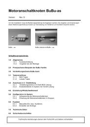
<strong>Instal<strong>la</strong>tion</strong> <strong>of</strong> <strong>your</strong> <strong>pet</strong> <strong>door</strong><br />
<strong>Please</strong> <strong>read</strong> <strong>the</strong> <strong>instructions</strong><br />
<strong>Pose</strong> <strong>de</strong> <strong>la</strong> chatière<br />
Prière <strong>de</strong> lire attentivement <strong>la</strong> notice<br />
Einbau <strong>de</strong>r Haustierk<strong>la</strong>ppe<br />
Anweisungen bitte sorgfältig durchlesen<br />
Instal<strong>la</strong>zione <strong>de</strong>l<strong>la</strong> gattaio<strong>la</strong>.<br />
Leggere attentamente le istruzioni<br />
Insta<strong>la</strong>ción <strong>de</strong> <strong>la</strong> puerta <strong>de</strong> mascota<br />
Lea atentamente <strong>la</strong>s instrucciones<br />
Insta<strong>la</strong>ção da porta para animais <strong>de</strong> estimação<br />
Leia as instruções<br />
ESPAÑOL<br />
DEUTSCH<br />
PORTUGUÊS
2<br />
ENGLISH<br />
CONTENTS<br />
1. ELECTRICAL INTERFERENCE...........................................................................1<br />
2. INSTALLATION......................................................................................................1<br />
3. CONNECTING POWER.......................................................................................1<br />
4. CONNECTING HOUSE ALARM.......................................................................1<br />
5. TURNING ON/OFF...............................................................................................2<br />
6. PAIRING COLLAR TAGS......................................................................................2<br />
7. WIPING ALL TAGS FROM THE MEMORY.....................................................2<br />
9. REPLACING COLLAR TAG BATTERIES..........................................................3<br />
10. REPLACING THE DOOR PANEL....................................................................3<br />
11. REPLACING THE CARTRIDGE.......................................................................4<br />
12. TROUBLESHOOTING........................................................................................4<br />
13. MAINTENANCE..................................................................................................5<br />
ALARM/ADAPTOR SPECIFICATIONS<br />
Re<strong>la</strong>y specifications:<br />
Switching Voltage: 120VAC, 30VDC - Max<br />
Contact Rating: (Current)1A<br />
Normal Close: (NC).<br />
Adaptor:<br />
Voltage: 12V - 1.5A<br />
DC connector 2.1mm ID (positive),<br />
5.5mm OD (negative)<br />
1. ELECTRICAL INTERFERENCE<br />
This <strong>door</strong> contains a sensitive radio receiver. Excessive levels <strong>of</strong> electrical interference can affect<br />
<strong>the</strong> range <strong>of</strong> <strong>the</strong> system. The following gui<strong>de</strong>lines will help to reduce electrical interference.<br />
Do not install <strong>the</strong> <strong>door</strong> near o<strong>the</strong>r RFID or microchip <strong>read</strong>ers or simi<strong>la</strong>r low frequency <strong>de</strong>vices.<br />
• Avoid obvious sources <strong>of</strong> electrical noise such as flickering lights<br />
• Avoid routing mains cables and DC mains adaptors close to <strong>the</strong> <strong>door</strong><br />
2. INSTALLATION<br />
Before installing <strong>your</strong> <strong>door</strong> you should consi<strong>de</strong>r<br />
how to manage <strong>the</strong> power and a<strong>la</strong>rm cables. You<br />
can choose to rout <strong>the</strong> cables insi<strong>de</strong> or outsi<strong>de</strong><br />
<strong>the</strong> wall cavity. Ei<strong>the</strong>r way you will need to make<br />
an allowance for <strong>the</strong>m.<br />
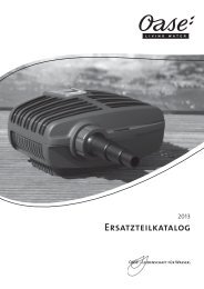
When cutting <strong>the</strong> hole in <strong>the</strong> wall you will need to<br />
make an extra cut out for <strong>the</strong> cables. The cut out<br />
should be 60mm wi<strong>de</strong> x 20mm high (2 ½” x ¾”) in<br />
<strong>the</strong> top right corner <strong>of</strong> <strong>the</strong> insi<strong>de</strong> wall.<br />
3. CONNECTING POWER<br />
Plug <strong>the</strong> power pack lead into <strong>the</strong> DC socket on<br />
<strong>the</strong> top <strong>of</strong> <strong>the</strong> <strong>door</strong>. Plug <strong>the</strong> o<strong>the</strong>r end into a<br />
power outlet nearby. Be sure to p<strong>la</strong>ce <strong>the</strong> power<br />
pack somewhere where it won’t overheat or get<br />
wet. If you hi<strong>de</strong> it in a wall be sure to leave some<br />
air space around it. Alternatively get a registered<br />
electrician to hardwire it in for you. Be sure to<br />
leave at least 200mm (8”) <strong>of</strong> loose cable to allow<br />
for easy removal <strong>of</strong> <strong>the</strong> cartridge.<br />
4. CONNECTING HOUSE ALARM<br />
The PC12 is equipped with an additional security<br />
a<strong>la</strong>rm in case <strong>the</strong> <strong>door</strong> panel does not close<br />
due to an obstruction. This a<strong>la</strong>rm can also be<br />
connected to <strong>your</strong> mains house a<strong>la</strong>rm by an<br />
electrician or pr<strong>of</strong>essional a<strong>la</strong>rm installer. The<br />
connectors for <strong>the</strong> a<strong>la</strong>rm are <strong>the</strong> green and<br />
orange connectors next to <strong>the</strong> power plug. Be<br />
sure to leave at least 200mm (8”) <strong>of</strong> loose cable<br />
to allow for easy removal <strong>of</strong> <strong>the</strong> cartridge.<br />
instal<strong>la</strong>tion extra cut<br />
20<br />
60<br />
ENGLISH<br />
1
2<br />
ENGLISH<br />
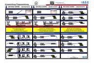
1 2 3<br />
5. TURNING ON/OFF<br />
Turn <strong>the</strong> <strong>door</strong> on by pushing <strong>the</strong> Power Button for 5 seconds (but less than 10). A green LED<br />
light will be on for 2 seconds to indicate that <strong>the</strong> <strong>door</strong> is on. When <strong>the</strong> <strong>door</strong> turns on it will<br />
automatically close <strong>the</strong> f<strong>la</strong>p.<br />
Turn <strong>the</strong> <strong>door</strong> <strong>of</strong>f by pushing <strong>the</strong> Power Button for 5 seconds (but less than 10). A red LED light<br />
will be on for 2 seconds to indicate that <strong>the</strong> <strong>door</strong> is on. When <strong>the</strong> <strong>door</strong> is turned <strong>of</strong>f it is still<br />
locked but it is not connected to <strong>the</strong> house a<strong>la</strong>rm.<br />
6. PAIRING COLLAR TAGS<br />
1. Short press <strong>the</strong> Tag Button for 5 seconds (but less than 10) to activate <strong>the</strong> tag <strong>read</strong>er<br />
function, a red LED will f<strong>la</strong>sh for 10 seconds, during this period <strong>the</strong> <strong>door</strong> is <strong>read</strong>y to <strong>read</strong> a<br />
new tag.<br />
2. Hold <strong>the</strong> col<strong>la</strong>r tag close to <strong>the</strong> <strong>door</strong>. A green LED light will f<strong>la</strong>sh to indicate that a new tag<br />
has been <strong>de</strong>tected.<br />
3. Press <strong>the</strong> Tag Button for 5 seconds (but less than 10). The LED will f<strong>la</strong>sh green for 2 seconds<br />
to indicate that <strong>the</strong> tag has been successfully paired with <strong>the</strong> <strong>door</strong> and saved in <strong>the</strong> memory.<br />
You may pair up to 16 tags.<br />
Old Tag: If <strong>the</strong> tag is al<strong>read</strong>y in <strong>the</strong> memory, <strong>the</strong> green led light will turn on for 2 seconds to<br />
indicate that <strong>the</strong> tag is al<strong>read</strong>y in <strong>the</strong> memory.<br />
Memory full: If <strong>the</strong> memory is full, <strong>the</strong> tag <strong>read</strong>er function will cancel and <strong>the</strong> Tag Button will<br />
f<strong>la</strong>sh a red LED light for 3 seconds to indicate that <strong>the</strong>re are 16 tags al<strong>read</strong>y stored and no more<br />
can be <strong>read</strong>.<br />
7. WIPING ALL TAGS FROM THE MEMORY<br />
In <strong>the</strong> unlikely circumstance you need to wipe all tags from <strong>the</strong> <strong>door</strong>s memory, press <strong>the</strong> Tag<br />
Button for 10 seconds or more, a red LED will light for 2 seconds to indicate that <strong>the</strong> memory has<br />
been wiped and it is now empty (16tags erased).<br />
You may not erase an individual tag.<br />
1. Power Button<br />
2. Tag button<br />
3. LED light indicator<br />
8. FITTING COLLAR TAG TO YOUR PET<br />
To ensure <strong>the</strong> col<strong>la</strong>r tags work well <strong>the</strong>y should be attached<br />
directly to <strong>your</strong> <strong>pet</strong>s col<strong>la</strong>r and <strong>the</strong> col<strong>la</strong>r should not be over or<br />
un<strong>de</strong>r tightened. The tag should sit on <strong>the</strong> front <strong>of</strong> <strong>your</strong> <strong>pet</strong>’s<br />
neck in front <strong>of</strong> it’s throat.<br />
9. REPLACING COLLAR TAG BATTERIES<br />
Col<strong>la</strong>r tag batteries will need to be rep<strong>la</strong>ced approximately every<br />
12 months. Simply twist <strong>the</strong> back cover <strong>of</strong>f using a coin and swap<br />
<strong>the</strong> battery with a fresh new CR2477 cell. Ensure it is inserted <strong>the</strong><br />
correct way around with <strong>the</strong> positive si<strong>de</strong> facing in.<br />
We recommend using good quality batteries to ensure a longer<br />
lifetime. Do not leave a battery in an unused tag. It will drain <strong>the</strong><br />
battery.<br />
10. REPLACING THE DOOR PANEL<br />
A. DOOR PANEL REMOVAL<br />
In <strong>the</strong> event you need to remove <strong>the</strong> <strong>door</strong>’s f<strong>la</strong>p press <strong>the</strong> Power<br />
Button for 10 seconds or more, <strong>the</strong> f<strong>la</strong>p will automatically unlock.<br />
With <strong>the</strong> internal locking mechanism released, <strong>your</strong> f<strong>la</strong>p is now<br />
<strong>read</strong>y for removal.<br />
The <strong>door</strong> will remain unlocked for 15 seconds.<br />
<strong>Please</strong> ensure that you push <strong>the</strong> f<strong>la</strong>p upwards slowly and never force or rush <strong>the</strong> removal.<br />
B. EMERGENCY DOOR PANEL REMOVAL<br />
If <strong>the</strong> cartridge has failed or <strong>the</strong>re is no power you can remove <strong>the</strong> f<strong>la</strong>p by inserting a long thin<br />
nail or wire into <strong>the</strong> hole in <strong>the</strong> middle <strong>of</strong> <strong>the</strong> cartridge (just below <strong>the</strong> buttons). You only need<br />
to press lightly to release <strong>the</strong> lock and at <strong>the</strong> same time you need to pull/push <strong>the</strong> <strong>door</strong> f<strong>la</strong>p<br />
upwards and <strong>the</strong>n remove <strong>the</strong> nail / screw driver to pull <strong>the</strong> f<strong>la</strong>p <strong>the</strong> rest <strong>of</strong> <strong>the</strong> way out.<br />
<strong>Please</strong> ensure that you push <strong>the</strong> f<strong>la</strong>p upwards slowly and never force or rush <strong>the</strong> removal.<br />
ENGLISH<br />
3
4<br />
ENGLISH<br />
C. INSERTING A NEW DOOR PANEL<br />
Gently insert <strong>the</strong> new f<strong>la</strong>p from above with <strong>the</strong> gear tracks facing <strong>the</strong> wall, being careful to keep<br />
it aligned, once it has engaged <strong>the</strong> gears you should be able to let it go and it will sli<strong>de</strong> down and<br />
close by itself. If it jams it might be out <strong>of</strong> alignment, if so <strong>the</strong>n gently pull it back out and start<br />
again.<br />
11. REPLACING THE CARTRIDGE<br />
One <strong>of</strong> <strong>the</strong> <strong>de</strong>sign features <strong>of</strong> <strong>the</strong> PC12 is that if <strong>the</strong>re is a fault with <strong>the</strong> electronics you can<br />
remove <strong>the</strong> cartridge and send away for repair or rep<strong>la</strong>cement without having to remove <strong>the</strong><br />
entire <strong>door</strong>.<br />
Tools Required: Small Philips screw driver<br />
A. REMOVING THE CARTRIDGE<br />
To remove <strong>the</strong> cartridge first you must remove <strong>the</strong> <strong>door</strong> panel, see previous page <strong>instructions</strong>.<br />
Once <strong>the</strong> <strong>door</strong> panel is removed you can remove <strong>the</strong> cartridge. First remove <strong>the</strong> 2 small Philips<br />
screws from <strong>the</strong> back <strong>of</strong> <strong>the</strong> cartridge. Then pull <strong>the</strong> cartridge down and backwards to remove it.<br />
Be careful to unplug <strong>the</strong> power and a<strong>la</strong>rm cables upon removal.<br />
B. INSTALLING THE CARTRIDGE<br />
Attaching a new cartridge is <strong>the</strong> opposite <strong>of</strong> removal: plug it in, push it in forwards and up and<br />
attach <strong>the</strong> two small screws at <strong>the</strong> rear. Then insert <strong>the</strong> f<strong>la</strong>p as per above <strong>instructions</strong>.<br />
12. TROUBLESHOOTING<br />
Symptom: A<strong>la</strong>rm is going <strong>of</strong>f<br />
Door Panel might be Blocked: The PC12 is equipped with an additional security a<strong>la</strong>rm which will<br />
kick in after 2 unsuccessful attempts to close. In <strong>the</strong> case <strong>the</strong> <strong>door</strong> panel does not close due to<br />
an obstruction please remove <strong>the</strong> object that is blocking <strong>the</strong> f<strong>la</strong>p. Then with a short push <strong>of</strong> <strong>the</strong><br />
(Power Button) <strong>the</strong> <strong>door</strong> will initiate its closing procedure.<br />
Door panel might be stuck: Dirty <strong>door</strong> tracks may be causing <strong>the</strong> <strong>door</strong> panel to stick, remove <strong>the</strong><br />
f<strong>la</strong>p as per <strong>instructions</strong> and give <strong>the</strong> tracks a thorough clean out.<br />
The Sensitivity <strong>of</strong> <strong>the</strong> <strong>door</strong> may need to be adjusted: Over time as components wear you may<br />
need to make a one-time adjustment to <strong>the</strong> sensitivity <strong>of</strong> <strong>the</strong> <strong>door</strong> to ensure it doesn’t trigger<br />
false a<strong>la</strong>rms. See Maintenance section.<br />
Symptom: The Door is stuck open<br />
• Check that <strong>the</strong> <strong>door</strong> is turned on<br />
• Check <strong>the</strong> <strong>door</strong> tracks for obstructions and clean <strong>the</strong>m. Then with a short push <strong>of</strong> <strong>the</strong><br />
(Power Button) <strong>the</strong> <strong>door</strong> will initiate its closing procedure.<br />
• The <strong>door</strong> panel may have become misaligned. Remove and reinsert <strong>the</strong> <strong>door</strong> panel as per<br />
<strong>the</strong> <strong>instructions</strong>.<br />
Symptom: The <strong>door</strong> isn’t letting my <strong>pet</strong> in or out<br />
• Check that <strong>the</strong> col<strong>la</strong>r tag is still attached to <strong>your</strong> <strong>pet</strong>’s col<strong>la</strong>r<br />
• Check that <strong>the</strong> tag is paired with <strong>the</strong> <strong>door</strong> (see pairing tags). Rep<strong>la</strong>ce <strong>the</strong> col<strong>la</strong>r tag batteries<br />
Symptom: The Door becomes stuck during opening/closing<br />
Opening: If <strong>the</strong> <strong>door</strong> panel becomes stuck during <strong>the</strong> opening process, it will stop and <strong>the</strong>n close<br />
after 5 seconds. During this period <strong>the</strong> red LED will f<strong>la</strong>sh to indicate <strong>the</strong>re is a problem.<br />
Closing: If <strong>the</strong> <strong>door</strong> panel becomes stuck during <strong>the</strong> closing process, it will stop and <strong>the</strong>n<br />
re-open. After 5 seconds it will attempt to close again.<br />
If <strong>the</strong> <strong>door</strong> is unable to close, <strong>the</strong> <strong>door</strong> panel will stop and an internal buzzer will activate in<br />
conjunction with <strong>the</strong> external a<strong>la</strong>rm (optional). The red LED will begin f<strong>la</strong>shing if this problem<br />
occurs.<br />
After solving <strong>the</strong> problem, press <strong>the</strong> Power Button for 5 seconds (but less than 10) and <strong>the</strong> <strong>door</strong><br />
will close. If <strong>the</strong> problem persists, adjust <strong>the</strong> <strong>door</strong> sensitivity.<br />
13. MAINTENANCE<br />
A. KEEP DOOR TRACKS CLEAR<br />
To prevent <strong>the</strong> <strong>door</strong> panel from jamming <strong>the</strong> tracks in <strong>the</strong> si<strong>de</strong>s and bottom <strong>of</strong> <strong>the</strong> <strong>door</strong> should<br />
be kept clean and free <strong>of</strong> <strong>de</strong>bris at all times.<br />
B. CHANGING BATTERIES<br />
Batteries in <strong>the</strong> col<strong>la</strong>r tag need to be changed periodically so it pays to check <strong>the</strong>m every so<br />
<strong>of</strong>ten. To remove and rep<strong>la</strong>ce col<strong>la</strong>r tag see section 9.<br />
C. ADJUST THE DOOR SENSITIVITY<br />
Over time as <strong>the</strong> motor and components <strong>of</strong><br />
<strong>the</strong> dog <strong>door</strong> wear you may need to adjust <strong>the</strong><br />
<strong>door</strong> sensitivity to ensure it operates normally<br />
and that it does not trigger a false a<strong>la</strong>rm. To<br />
do this you need to adjust <strong>the</strong> small dial in <strong>the</strong><br />
back <strong>of</strong> <strong>the</strong> cartridge with a small F<strong>la</strong><strong>the</strong>ad<br />
screw driver.<br />
• Turning <strong>the</strong> screw driver anticlockwise<br />
witll make it become more sensitive.<br />
• Turning <strong>the</strong> screw driver clockwise will<br />
make it become less sensitive.<br />
ENGLISH<br />
5
6<br />
FRANÇAIS<br />
CONTENU<br />
1. INTERFERENCE ELECTRIQUE.....................................................................................7<br />
2. INSTALLATION...................................................................................................................7<br />
3. CONNECTION ELECTRIQUE.......................................................................................7<br />
4. CONNECTION A L’ALARME DE LA MAISON........................................................7<br />
5. MARCHE/ARRET...............................................................................................................8<br />
6. ASSOCIATION DE DISQUES D’IDENTIFICATION..............................................8<br />
7. EFFACER TOUS LES DISQUES D’IDENTIFICATION DE LA MEMOIRE......8<br />
8. METTRE LE DISQUE D’IDENTIFICATION A VOTRE ANIMAL........................9<br />
9. CHANGER LES PILES DU DISQUE D’IDENTIFICATION...................................9<br />
10. REMPLACER LE BATTANT DE LA PORTE............................................................9<br />
11. CHANGEMENT DE CARTOUCHE........................................................................10<br />
12. DEPANNAGE.................................................................................................................10<br />
13. ENTRETIEN.....................................................................................................................11<br />
SPECIFICATIONS ALARME/ADAPTATEUR<br />
Spécifications du re<strong>la</strong>is:<br />
Changer <strong>de</strong> voltage: 120VAC, 30VDC - max<br />
Cote contact: (Courant) 1A<br />
Normallement fermé: (NF).<br />
Adaptateur:<br />
Voltage: 12V - 1.5A<br />
DC adaptateur: 2.1mm prise d’entrée<br />
(positive) 5.5mm prise <strong>de</strong> sortie (négative)<br />
1. INTERFERENCE ELECTRIQUE<br />
La porte contient un récepteur radio sensible. Un haut niveau d’interférence électrique peut<br />
avoir une influence sur <strong>la</strong> portée du système. Les indications suivantes ai<strong>de</strong>ront à réduire<br />
l’interférence électrique.<br />
Ne pas installer <strong>la</strong> porte près d’une autre source <strong>de</strong> fréquence radio à basses on<strong>de</strong>s ou d’un autre<br />
lecteur <strong>de</strong> puces électroniques.<br />
• Eviter <strong>de</strong>s sources <strong>de</strong> bruit électrique évi<strong>de</strong>ntes telle qu’une lumière vacil<strong>la</strong>nte<br />
• Eviter <strong>de</strong> faire passer <strong>de</strong>s fils électriques ou <strong>de</strong> mettre <strong>de</strong>s adaptateurs DC près <strong>de</strong> <strong>la</strong> porte<br />
2. INSTALLATION<br />
Avant d’installer <strong>la</strong> porte vous <strong>de</strong>vez prévoir l’instal<strong>la</strong>tion <strong>de</strong>s fils électrique et <strong>de</strong> l’a<strong>la</strong>rme. Vous<br />
pouvez choisir <strong>de</strong> les faire passer à l’intérieur ou à<br />
l’extérieur du mur.<br />
Quand vous faites le trou dans le mur vous <strong>de</strong>vez faire<br />
une coupure <strong>de</strong> plus pour les fils. La coupure doit être<br />
<strong>de</strong> 60mm <strong>de</strong> <strong>la</strong>rge et <strong>de</strong> 20mm <strong>de</strong> haut, en haut à droite<br />
60<br />
dans le mur intérieur.<br />
3. CONNECTION ELECTRIQUE<br />
Brancher l’adaptateur électrique dans <strong>la</strong> prise DC<br />
en haut <strong>de</strong> <strong>la</strong> porte. Connecter l’autre côté <strong>de</strong><br />
l’adaptateur à une prise proche. Faites attention <strong>de</strong><br />
p<strong>la</strong>cer l’adaptateur à un endroit où il ne subisse pas<br />
<strong>de</strong> surchauffe ni d’humidité. Si vous le mettez à<br />
l’intérieur du mur faites attention <strong>de</strong> <strong>la</strong>isser assez<br />
d’espace <strong>de</strong> venti<strong>la</strong>tion autour. Sinon <strong>de</strong>man<strong>de</strong>r à un<br />
électricien agréé <strong>de</strong> faire l’instal<strong>la</strong>tion. Laisser au moins<br />
200mm <strong>de</strong> fils supplémentaire pour pouvoir retirer <strong>la</strong><br />
cartouche plus facilement.<br />
4. CONNECTION A L’ALARME DE LA<br />
MAISON<br />
La PC12 est équipée d’une a<strong>la</strong>rme <strong>de</strong> sécurité<br />
supplémentaire au cas où le battant <strong>de</strong> porte ne se<br />
ferme pas à cause d’une obstruction. Cette a<strong>la</strong>rme<br />
peut être connectée directement à l’a<strong>la</strong>rme <strong>de</strong> <strong>la</strong><br />
maison par un électricien ou un instal<strong>la</strong>teur d’a<strong>la</strong>rme<br />
pr<strong>of</strong>essionel. L’embout connecteur pour l’a<strong>la</strong>rme est<br />
vert et orange à côté <strong>de</strong> <strong>la</strong> prise courant.<br />
Laisser au moins 200mm <strong>de</strong> fils supplémentaire pour<br />
pouvoir retirer <strong>la</strong> cartouche plus facilement.<br />
Suivre les <strong>instructions</strong> ci-jointes pour finir l’instal<strong>la</strong>tion.<br />
instal<strong>la</strong>tion extra cut<br />
20<br />
FRANÇAIS<br />
7
8<br />
FRANÇAIS<br />
1 2 3<br />
5. MARCHE/ARRET<br />
Metter <strong>la</strong> porte en marche en appuyant sur le bouton marche/arrêt pendant 5 secon<strong>de</strong>s ou plus<br />
(mais moins <strong>de</strong> 10 secon<strong>de</strong>s). Une LED verte clignotante indique que <strong>la</strong> porte est en marche. Le<br />
battant se ferme alors automatiquement. Eteigner <strong>la</strong> porte en appuyant sur le bouton marche/<br />
arrêt pendant 5 secon<strong>de</strong>s ou plus (mais moins <strong>de</strong> 10 secon<strong>de</strong>s). Une LED rouge clignote pendant<br />
2 secon<strong>de</strong>s pour indiquer que <strong>la</strong> porte est arrêtée. Quand <strong>la</strong> porte est éteinte elle n’est plus<br />
connectée à l’a<strong>la</strong>rme <strong>de</strong> <strong>la</strong> maison.<br />
NOTE: Quand <strong>la</strong> porte est mise en marche pour <strong>la</strong> première fois elle essaiera <strong>de</strong> fermer et<br />
vérouiller le battant automatiquement. Une LED verte clignote à ce moment. Si le battant ne<br />
se ferme pas à cause d’une obstruction, enlever l’objet qui bloque le battant. Une LED rouge<br />
clignotante indique que <strong>la</strong> porte ne peut pas se fermer et l’a<strong>la</strong>rme sera activée. Pour remettre le<br />
système à jour appuyer sur le bouton marche/arrêt pendant 5 secon<strong>de</strong>s ou plus (mais moins <strong>de</strong><br />
10 secon<strong>de</strong>s) pour que le processus recommence.<br />
6. ASSOCIATION DE DISQUES D’IDENTIFICATION<br />
1. Appuyer sur le bouton du disque d’i<strong>de</strong>ntification pendant 5 secon<strong>de</strong>s ou plus (mais moins<br />
<strong>de</strong> 10 secon<strong>de</strong>s) pour activer <strong>la</strong> lecture. Une LED rouge clignote pendant 15 secon<strong>de</strong>s,<br />
pendant lesquelles <strong>la</strong> porte est prête à être associée au disque d’i<strong>de</strong>ntification.<br />
2. Mettre le disque près <strong>de</strong> <strong>la</strong> porte. Une LED verte clignotante indique que le nouveau disque<br />
a été reconnu.<br />
3. Appuyer sur le bouton du disque d’i<strong>de</strong>ntification pendant 5 secon<strong>de</strong>s ou plus (mais moins<br />
<strong>de</strong> 10 secon<strong>de</strong>s) pour l’enregistrer. La LED reste verte pendant 2 secon<strong>de</strong>s pour indiquer que<br />
le disque et <strong>la</strong> porte sont maintenant associés et en mémoire. Vous pouvez associer jusqu’à<br />
16 disques d’i<strong>de</strong>ntification.<br />
Disques déjà associés: Si le disque est déjà en mémoire, <strong>la</strong> LED verte s’allumera pendant 2<br />
secon<strong>de</strong>s pour l’indiquer.<br />
Mémoire saturée: Si <strong>la</strong> mémoire est pleine, le lecteur <strong>de</strong> disque s’arrête et <strong>la</strong> LED rouge clignote<br />
pendant 3 secon<strong>de</strong>s pour indiquer qu’il y a déjà 16 disques associés.<br />
7. EFFACER TOUS LES DISQUES D’IDENTIFICATION DE LA MEMOIRE<br />
Si vous <strong>de</strong>vez effacer tous les disques qui sont en mémoire, appuyer sur le bouton du disque<br />
d’i<strong>de</strong>ntification pendant 10 secon<strong>de</strong>s ou plus, une LED rouge s’allume pendant 2 secon<strong>de</strong>s pour<br />
indiquer que <strong>la</strong> mémoire a été effacée et est maintenant vi<strong>de</strong> (16 disques d’i<strong>de</strong>ntification effacés)<br />
Il est impossible d’effacer un seul disque.<br />
1. Bouton marche/arrêt<br />
2. Bouton du disque<br />
d’i<strong>de</strong>ntification<br />
3. LED<br />
8. METTRE LE DISQUE D’IDENTIFICATION A<br />
VOTRE ANIMAL<br />
Pour être sûr que le disque marche bien il faut l’attacher<br />
directement au collier <strong>de</strong> votre animal. Le collier ne doit pas être<br />
trop serré ou trop lâche. Le disque doit être à l’avant sur <strong>la</strong> gorge<br />
<strong>de</strong> l’animal.<br />
9. CHANGER LES PILES DU DISQUE<br />
D’IDENTIFICATION<br />
Les piles <strong>de</strong>vront être remp<strong>la</strong>cées tous les 24 mois environ. Tourner<br />
simplement le couvercle à l’arrière du disque en utilisant une pièce<br />
<strong>de</strong> monnaie et metter une nouvelle pile CR2477. La face positive <strong>de</strong><br />
<strong>la</strong> pile doit vous faire face.<br />
Nous vous recommandons d’utiliser <strong>de</strong>s piles <strong>de</strong> bonne qualité pour<br />
une durée <strong>de</strong> vie optimale. Ne pas <strong>la</strong>isser une pile dans un disque<br />
non-utilisé car <strong>la</strong> pile se décharge.<br />
10. REMPLACER LE BATTANT DE LA PORTE<br />
A. REPLACEMENT<br />
Si vous <strong>de</strong>vez enlever le battant appuyer sur le bouton marche/arrêt pendant 10 secon<strong>de</strong>s ou<br />
plus et le battant se déverrouillera automatiquement. Avec le système <strong>de</strong> vérrouil<strong>la</strong>ge interne<br />
annulé le battant peut être enlever.<br />
La porte sera déverrouillée pendant 15 secon<strong>de</strong>s.<br />
Faites attention <strong>de</strong> pousser le battant vers le haut doucement, sans forcer ni vous dépêcher <strong>de</strong><br />
l’enlever.<br />
B. REMPLACEMENT D’URGENCE<br />
Si <strong>la</strong> cartouche ne marche pas ou qu’il n’y a pas <strong>de</strong> courant vous pouvez enlever le battant en<br />
insérant un long fil métallique ou un clou fin dans le trou au milieu <strong>de</strong> <strong>la</strong> cartouche (juste en<br />
<strong>de</strong>ssous <strong>de</strong>s boutons). Presser doucement pour déverrouiller et en même temps pousser/tirer<br />
le battant vers le haut. Enlever ensuite le long fil métallique ou le clou fin pour enlever le battant<br />
complétement.<br />
Faites attention <strong>de</strong> pousser le battant vers le haut doucement, sans forcer ni vous dépêcher <strong>de</strong><br />
l’enlever.<br />
FRANÇAIS<br />
9
10<br />
FRANÇAIS<br />
C. INSERER UN NOUVEAU BATTANT<br />
Insérer doucement un nouveau battant en ayant le côté marqué en face du mur et en faisant<br />
attention à gar<strong>de</strong>r le battant bien aligné. Une fois engagé le battant glissera et se fermera seul.<br />
S’il se coince c’est qu’il n’est pas bien aligné. Retirer le doucement et recommencer.<br />
11. CHANGEMENT DE CARTOUCHE<br />
Une <strong>de</strong>s caractéristiques <strong>de</strong> PC12 est qu’en cas <strong>de</strong> faute électronique vous pouvez enlever <strong>la</strong><br />
cartouche et l’envoyer pour réparation sans avoir à démonter <strong>la</strong> porte entière.<br />
Outils nécessaire: Petit tournevis Phillips<br />
A. ENLEVER LA CARTOUCHE<br />
Pour enlever <strong>la</strong> cartouche vous <strong>de</strong>vez d’abord enlever le battant <strong>de</strong> porte (voir <strong>instructions</strong> page<br />
précé<strong>de</strong>nte). Quand le battant est enlevé, vous pouvez enlever <strong>la</strong> cartouche en <strong>de</strong>vissant les<br />
<strong>de</strong>ux vis <strong>de</strong>rrière <strong>la</strong> cartouche et en <strong>la</strong> tirant vers le bas puis vers l’arrière. Faites attention <strong>de</strong><br />
<strong>de</strong>brancher ensuite les fils électriques et <strong>de</strong> l’a<strong>la</strong>rme.<br />
B. INSTALLER LA CARTOUCHE<br />
Remettre une cartouche et le contraire <strong>de</strong> l’étape ci-<strong>de</strong>ssus: Brancher <strong>la</strong> cartouche, pousser <strong>la</strong> en<br />
avant puis vers le haut et revisser les vis <strong>de</strong>rrière <strong>la</strong> cartouche. Puis insérer le battant en suivant<br />
les <strong>instructions</strong> ci-<strong>de</strong>ssus.<br />
12. DEPANNAGE<br />
L’a<strong>la</strong>rme se met en route<br />
ELe battant est bloqué: PC12 a une a<strong>la</strong>rme <strong>de</strong> sécurité supplémentaire qui s’active après ne pas<br />
avoir réussi à se fermer <strong>de</strong>ux fois.<br />
S’il y a obstruction, enlever l’object qui bloque le battant. Appuyer ensuite sur le bouton marche/<br />
arrêt pendant 5 secon<strong>de</strong>s ou plus (mais pas plus <strong>de</strong> 10 secon<strong>de</strong>s) et <strong>la</strong> porte essaie <strong>de</strong> se fermer<br />
à nouveau.<br />
Le battant peut être coincé: La saleté accummulée entre <strong>la</strong> porte et le battant peut être à<br />
l’origine du problème. Enlever le battant en suivant les <strong>instructions</strong> et nettoyer <strong>la</strong> porte à <strong>la</strong><br />
jointure du battant.<br />
La sensibilité <strong>de</strong> <strong>la</strong> porte doit être reglée: Avec les années il est possible que <strong>la</strong> porte ait besoin<br />
d’un ajustement pour que <strong>la</strong> sensibilité n’active pas <strong>de</strong> fauses a<strong>la</strong>rmes. Voir <strong>la</strong> partie ENTRETIEN.<br />
La porte reste ouverte<br />
• Vérifier que <strong>la</strong> porte soit en marche<br />
• Vérifier s’il y a obstruction et enlever <strong>la</strong> ou nettoyer. Appuyer ensuite sur le bouton marche/<br />
arrêt pendant 5 secon<strong>de</strong>s ou plus (mais pas plus <strong>de</strong> 10 secon<strong>de</strong>s) et <strong>la</strong> porte essaie <strong>de</strong> se<br />
fermer à nouveau<br />
• Le battant a pu se décaler. Enlever le et remetter le en suivant les <strong>instructions</strong><br />
L’animal ne peut ni entrer, ni sortir<br />
• Vérifier que le disque d’i<strong>de</strong>ntification soit toujours sur le collier<br />
• Vérifier que le disque d’i<strong>de</strong>ntification soit associé à <strong>la</strong> porte. Remp<strong>la</strong>cer les piles si nécessaire<br />
La porte se coince en s’ouvrant ou en se fermant<br />
A l’ouverture: Si <strong>la</strong> porte se coince, elle s’arrête et se ferme après 5 secon<strong>de</strong>s. La LED rouge<br />
s’allume pour indiquer qu’il y a un problème.<br />
A <strong>la</strong> fermeture: Si <strong>la</strong> porte se coince, elle s’arrête et s’ouvre à nouveau. Après 5 secon<strong>de</strong>s <strong>la</strong> porte<br />
essaie <strong>de</strong> se fermer à nouveau. Si <strong>la</strong> porte ne peut pas se fermer, le battant s’arrête et une a<strong>la</strong>rme<br />
interne retanti en conjonction avec l’a<strong>la</strong>rme externe (option).<br />
La LED rouge clignote s’il y a un problème. Après avoir ressolu le problème appuyer sur le bouton<br />
marche/arrêt pendant 5 secon<strong>de</strong>s ou plus (mais pas plus <strong>de</strong> 10 secon<strong>de</strong>s) et <strong>la</strong> porte se ferme. Si<br />
le problème persiste ajuster <strong>la</strong> sensibilité <strong>de</strong> <strong>la</strong> porte.<br />
13. ENTRETIEN<br />
A. GARDER LA PORTE PROPRE<br />
Pour que le battant ne se coince pas, nettoyer <strong>la</strong> porte régulièrement et enlever les <strong>de</strong>bris.<br />
B. CHANGER LES PILES<br />
Voir section 9.<br />
C. AJUSTER LA SENSIBILITE DE LA PORTE<br />
Avec les années il est possible que <strong>la</strong> porte ait besoin d’un ajustement pour que <strong>la</strong> sensibilité<br />
n’active pas <strong>de</strong> fausses a<strong>la</strong>rmes. Pour faire ca, régler le cadran au dos <strong>de</strong> <strong>la</strong> cartouche avec un<br />
tournevis à tête p<strong>la</strong>te.<br />
• Tourner dans le sens contraire <strong>de</strong>s aiguilles d’une montre pour plus <strong>de</strong> sensibilité.<br />
• Tourner dans le sens <strong>de</strong>s aiguilles d’une montre pour moins <strong>de</strong> sensibilité.<br />
FRANÇAIS<br />
11
12<br />
DEUTSCH<br />
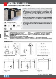
instal<strong>la</strong>tion extra cut<br />
INHALT<br />
1. ELEKTRISCHE STÖREINFLÜSSE....................................................................13<br />
2. INSTALLATION....................................................................................................13<br />
3. STROMANSCHLUSS..........................................................................................13<br />
4. ANSCHLUSS DES HAUSALARMS.................................................................13<br />
5. AN-/ABSCHALTEN.............................................................................................14<br />
6. KENNZEICHNUNG VON HALSBANDANHÄNGERN..............................14<br />
7. LŐSCHEN ALLER ANHÄNGER AUS DEM SPEICHER.............................14<br />
8. ANBRINGEN DES HALSBANDANHÄNGERS AN DAS HAUSTIER.....14<br />
9. ERSETZEN DER HALSBANDANHÄNGERBATTERIEN............................15<br />
10. ERSETZEN DER SCHWINGTÜR...................................................................15<br />
11. ERSETZEN DER PATRONE............................................................................16<br />
13. WARTUNG..........................................................................................................17<br />
TECHNISCHE DATEN DES ALARMS/ADAPTERS<br />
Technische Daten <strong>de</strong>s Re<strong>la</strong>is:<br />
Schaltspannung: 120V Wechselspannung,<br />
30V Gleichstromspannung-Max.<br />
Kontaktbe<strong>la</strong>stbarkeit: (Stromstärke) 1A<br />
Im Normalzustand geöffneter Kontakt: (Schließer).<br />
Adapter:<br />
Spannung: 12V – 1.5A<br />
Gleichstromsteckverbin<strong>de</strong>r:<br />
2,1mm Innendurchmesser (positiv),<br />
5,5mm Außendurchmesser (negativ)<br />
1. ELEKTRISCHE STÖREINFLÜSSE<br />
Diese Haustierk<strong>la</strong>ppe besitzt einen empfindlichen Funkempfänger. Zu hohe elektrische<br />
Stőreinflüsse kőnnen die Reichweite <strong>de</strong>s System beeinträchtigen. Die folgen<strong>de</strong>n Hinweise dienen<br />
dazu, elektrische Stőreinflüsse zu reduzieren.<br />
Die K<strong>la</strong>ppe nicht in <strong>de</strong>r Nähe von an<strong>de</strong>ren RFID-, Mikrochiplese- o<strong>de</strong>r ähnlichen<br />
Nie<strong>de</strong>rfrequenzgeräten installieren.<br />
• Offensichtliche elektrische Stőrquellen, wie zum Beispiel f<strong>la</strong>ckern<strong>de</strong> Leuchten, vermei<strong>de</strong>n<br />
• Das Verlegen von Netzleitungen sowie Gleichstromnetzadapter in <strong>de</strong>r Nähe <strong>de</strong>r K<strong>la</strong>ppe<br />
vermei<strong>de</strong>n<br />
2. INSTALLATION<br />
Vor <strong>de</strong>r <strong>Instal<strong>la</strong>tion</strong> <strong>de</strong>r K<strong>la</strong>ppe sollte in Betracht gezogen wer<strong>de</strong>n, wie die Strom- und A<strong>la</strong>rmkabel<br />
gehandhabt wer<strong>de</strong>n. Es besteht die Wahl, die Kabel in <strong>de</strong>r Wand o<strong>de</strong>r auβen zu verlegen. Sie<br />
műssen in je<strong>de</strong>m Fall berűcksichtigt wer<strong>de</strong>n.<br />
Wenn ein Loch in <strong>de</strong>r Wand gemacht wird, muss eine<br />
eigene Őffnung extra fűr die Kabel gemacht wer<strong>de</strong>n.<br />
Diese Őffnung sollte 60mm breit x 20mm hoch sein<br />
und sich in <strong>de</strong>r oberen rechten Ecke <strong>de</strong>r Innenwand<br />
befin<strong>de</strong>n.<br />
3. STROMANSCHLUSS<br />
Netzteilkabel in die Gleichstromsteckdose oben<br />
an <strong>de</strong>r K<strong>la</strong>ppe einstecken. Das an<strong>de</strong>re En<strong>de</strong><br />
in die nächstliegen<strong>de</strong> Steckdose einstecken.<br />
Sicherstellen, dass das Netzteil so p<strong>la</strong>tziert wird,<br />
dass es nicht űberhitzen o<strong>de</strong>r nass wer<strong>de</strong>n kann.<br />
Wird es in <strong>de</strong>r Wand verborgen, dafür sorgen, dass<br />
sich ein ausreichen<strong>de</strong>r Luftraum darum herum<br />
befin<strong>de</strong>t. An<strong>de</strong>rnfalls wen<strong>de</strong>n Sie sich an einen<br />
Elektr<strong>of</strong>achmann, um das Gerät fest zu verdrahten.<br />
Sicherstellen, dass min<strong>de</strong>stens 200mm loses Kabel<br />
zur Verfügung stehen, um die Patrone einfach<br />
entfernen zu können.<br />
4. ANSCHLUSS DES HAUSALARMS<br />
Die PC12 ist mit einem zusätzlichen Sicherheitsa<strong>la</strong>rm<br />
ausgerűstet fűr <strong>de</strong>n Fall, dass die K<strong>la</strong>ppe aufgrund<br />
eines Hin<strong>de</strong>rnisses nicht or<strong>de</strong>ntlich schlieβt.<br />
Ein Elektr<strong>of</strong>achmann o<strong>de</strong>r ein pr<strong>of</strong>essioneller<br />
A<strong>la</strong>rmtechniker kann diesen A<strong>la</strong>rm auch an <strong>de</strong>n<br />
Haupthausa<strong>la</strong>rm anschlieβen. Die Verbindungen<br />
fűr <strong>de</strong>n A<strong>la</strong>rm sind die grűnen und orangen<br />
Steckverbin<strong>de</strong>r neben <strong>de</strong>m Netzstecker. Sicherstellen,<br />
dass min<strong>de</strong>stens 200mm loses Kabel zur Verfügung<br />
stehen, um die Patrone einfach entfernen zu können.<br />
Die beigefűgten <strong>Instal<strong>la</strong>tion</strong>sanweisungen befolgen,<br />
um die <strong>Instal<strong>la</strong>tion</strong> zu En<strong>de</strong> zu führen.<br />
5. AN-/ABSCHALTEN<br />
K<strong>la</strong>ppe einschalten, in<strong>de</strong>m <strong>de</strong>r An-/Ausschalter 5 Sekun<strong>de</strong>n <strong>la</strong>ng o<strong>de</strong>r länger (aber nicht länger<br />
als 10 Sekun<strong>de</strong>n) gedrűckt wird. Eine grűne Leuchtdio<strong>de</strong> leuchtet 2 Sekun<strong>de</strong>n <strong>la</strong>ng auf, um<br />
anzuzeigen, dass die K<strong>la</strong>ppe eingeschaltet ist. Wenn sich die K<strong>la</strong>ppe einschaltet, schlieβt sich die<br />
Schwingtür automatisch.<br />
K<strong>la</strong>ppe ausschalten, in<strong>de</strong>m <strong>de</strong>r An-/Ausschalter 5 Sekun<strong>de</strong>n <strong>la</strong>ng o<strong>de</strong>r länger (aber nicht länger<br />
als 10 Sekun<strong>de</strong>n) gedrűckt wird. Eine rote Leuchtdio<strong>de</strong> leuchtet 2 Sekun<strong>de</strong>n <strong>la</strong>ng auf, um<br />
anzuzeigen, dass die K<strong>la</strong>ppe ausgeschaltet ist. Wenn die K<strong>la</strong>ppe abgeschaltet ist, ist sie noch<br />
immer verriegelt, steht jedoch nicht mit <strong>de</strong>m Hausa<strong>la</strong>rm in Verbindung.<br />
20<br />
60<br />
DEUTSCH<br />
13
14<br />
DEUTSCH<br />
BITTE BEACHTEN: Wenn die K<strong>la</strong>ppe zum ersten Mal eingeschaltet wird, wird sie versuchen,<br />
die Schwingtür zu schlieβen und zu verriegeln. Während diese Vorgangs leuchtet eine grűne<br />
Leuchtdio<strong>de</strong>. Falls die Schwingtür wegen eines Hin<strong>de</strong>rnisses nicht or<strong>de</strong>ntlich schlieβt, das<br />
Hin<strong>de</strong>rnis, das die Schwingtür blockiert, entfernen. Eine blinken<strong>de</strong> rote Leuchtdio<strong>de</strong> zeigt an,<br />
dass die Schwingtür nicht schlieβt, und <strong>de</strong>r A<strong>la</strong>rm wird aktiviert. Zur Neueinstellung <strong>de</strong>n An-/<br />
Ausschalter 5 Sekun<strong>de</strong>n <strong>la</strong>ng o<strong>de</strong>r länger (aber nicht länger als 10 Sekun<strong>de</strong>n) drűcken, um <strong>de</strong>n<br />
Vorgang zu wie<strong>de</strong>rholen.<br />
1 2 3<br />
1. An-/Ausschalter<br />
2. Anhängerknopf<br />
3. Leuchtdio<strong>de</strong>nanzeige<br />
6. KENNZEICHNUNG VON HALSBANDANHÄNGERN<br />
1. Den Anhängerknopf kurz 5 Sekun<strong>de</strong>n <strong>la</strong>ng o<strong>de</strong>r länger (aber nicht länger als 10 Sekun<strong>de</strong>n)<br />
drűcken, um die Anhängerlesefunktion zu aktivieren. Ein rote Leuchtdio<strong>de</strong> blinkt 15<br />
Sekun<strong>de</strong>n <strong>la</strong>ng, während<strong>de</strong>ssen die K<strong>la</strong>ppe bereit ist, einen neuen Anhänger abzulesen.<br />
2. Halsbandanhänger nahe an die K<strong>la</strong>ppe halten. Eine grűne Leuchtdio<strong>de</strong> leuchtet auf, um<br />
anzuzeigen, dass <strong>de</strong>r neue Anhänger registriert wur<strong>de</strong>.<br />
3. Den Anhängerknopf 5 Sekun<strong>de</strong>n <strong>la</strong>ng o<strong>de</strong>r länger (aber nicht länger als 10 Sekun<strong>de</strong>n)<br />
drűcken, um <strong>de</strong>n Anhänger zu speichern. Die grüne Leuchtdio<strong>de</strong> leuchtet 2 Sekun<strong>de</strong>n <strong>la</strong>ng<br />
auf, um anzuzeigen, dass <strong>de</strong>r Anhänger erfolgreich von <strong>de</strong>r K<strong>la</strong>ppe gekennzeichnet und<br />
gespeichert wur<strong>de</strong>. Bis zu 16 Anhänger kőnnen gespeichert wer<strong>de</strong>n.<br />
Alter Anhänger: Falls sich <strong>de</strong>r Anhänger bereits im Speicher befin<strong>de</strong>t, leuchtet die grűne<br />
Leuchtdio<strong>de</strong> 2 Sekun<strong>de</strong>n <strong>la</strong>ng auf, um anzuzeigen, dass <strong>de</strong>r Anhänger bereits gespeichert ist.<br />
Voller Speicher: Sollte <strong>de</strong>r Speicher voll sein, erlischt die Anhängerlesefunktion und am<br />
Anhängerknopf leuchtet eine rote Leuchtdio<strong>de</strong> 3 Sekun<strong>de</strong>n <strong>la</strong>ng auf, um anzuzeigen, dass bereits<br />
16 Anhänger gespeichert sind und nicht mehr abgelesen wer<strong>de</strong>n kőnnen.<br />
7. LŐSCHEN ALLER ANHÄNGER AUS DEM SPEICHER<br />
In <strong>de</strong>m unwahrscheinlichen Fall, dass alle Anhänger aus <strong>de</strong>m K<strong>la</strong>ppenspeicher gelőscht wer<strong>de</strong>n<br />
sollen, <strong>de</strong>n Anhängerknopf 10 Sekun<strong>de</strong>n <strong>la</strong>ng o<strong>de</strong>r länger drűcken. Eine rote Leuchtdio<strong>de</strong><br />
leuchtet 2 Sekun<strong>de</strong>n <strong>la</strong>ng auf, um anzuzeigen, dass <strong>de</strong>r Speicher gelőscht wur<strong>de</strong> und nun leer ist<br />
(16 Anhänger gelőscht).<br />
Ein einzelner Anhänger kann nicht gelőscht wer<strong>de</strong>n.<br />
8. ANBRINGEN DES HALSBANDANHÄNGERS AN DAS<br />
HAUSTIER<br />
Um sicherzugehen, dass Halsbandanhänger richtig funktionieren, sollten<br />
sie direkt am Halsband <strong>de</strong>s Haustiers angebracht wer<strong>de</strong>n. Das Halsband<br />
sollte nicht zu stramm o<strong>de</strong>r zu locker sitzen. Der Anhänger sollte<br />
vorne am Hals auf <strong>de</strong>r Kehle <strong>de</strong>s Haustiers sitzen.<br />
9. ERSETZEN DER<br />
HALSBANDANHÄNGERBATTERIEN<br />
Halsbandanhängererbatterien müssen ungefähr alle 24 Monate<br />
ersetzt wer<strong>de</strong>n. Einfach <strong>de</strong>n Deckel hinten mit Hilfe einer Münze<br />
abschrauben und die Batterie mit einer neuen CR2477 Batterie<br />
austauschen. Sicherstellen, dass sie richtig eingesetzt ist, so dass die<br />
positive Seite nach außen zeigt.<br />
Es wird empfohlen, Batterien von guter Qualität zu benutzen, um<br />
eine längere Lebensdauer zu garantieren. Batterie nicht in einem<br />
Anhänger <strong>la</strong>ssen, <strong>de</strong>r nicht benutzt wird, da dies die Batterie entleert.<br />
10. ERSETZEN DER SCHWINGTÜR<br />
A. ENTFERNEN DER SCHWINGTÜR<br />
Falls die Schwingtür entfernt wer<strong>de</strong>n muss, <strong>de</strong>n An-/Ausschalter 10 Sekun<strong>de</strong>n <strong>la</strong>ng<br />
o<strong>de</strong>r länger drűcken und die Schwingtür entriegelt sich automatisch. Wenn <strong>de</strong>r interne<br />
Verriegelungsmechanismus freigegeben ist, kann die Schwingtür nun entfernt wer<strong>de</strong>n.<br />
Die Schwingtür bleibt 15 Sekun<strong>de</strong>n <strong>la</strong>ng entriegelt.<br />
Bitte sichergehen, dass die Schwingtür <strong>la</strong>ngsam nach oben geschoben wird und nie mit Gewalt<br />
o<strong>de</strong>r unter Zeitdruck entfernt wird.<br />
B. UNVORHERGESEHENES ENTFERNEN DER SCHWINGTÜR<br />
Falls die Patrone versagt o<strong>de</strong>r bei Stromausfall, kann die Schwingtür entfernt wer<strong>de</strong>n, in<strong>de</strong>m ein<br />
<strong>la</strong>nger, dünner Nagel o<strong>de</strong>r ein Stück Draht<br />
in das Loch in <strong>de</strong>r Mitte <strong>de</strong>r Patrone (gleich<br />
unterhalb <strong>de</strong>r Schalter) eingeführt wird.<br />
Lediglich leicht drücken, um die Verriegelung<br />
zu lösen und gleichzeitig die Schwingtür nach<br />
oben ziehen o<strong>de</strong>r drücken. Dann <strong>de</strong>n Nagel<br />
o<strong>de</strong>r Schraubenzieher entfernen, um die<br />
K<strong>la</strong>ppe ganz herausziehen zu können.<br />
Bitte dafür sorgen, dass die Schwingtür<br />
<strong>la</strong>ngsam nach oben geschoben wird und nie<br />
mit Gewalt o<strong>de</strong>r unter Zeitdruck entfernt<br />
wird.<br />
C. EINSETZEN EINER NEUEN SCHWINGTÜR<br />
Neue Schwingtür behutsam von oben einführen, wobei die Leitschienen zur Wand zeigen. Darauf<br />
achten, dass die Schwingtür or<strong>de</strong>ntlich ausgerichtet ist. Sobald die Leitschienen greifen, kann die<br />
Schwingtür losge<strong>la</strong>ssen wer<strong>de</strong>n und sollte von selbst nach unten gleiten und schließen. Sollte<br />
sie klemmen, ist sie mőglicherweise nicht gera<strong>de</strong> ausgerichtet. Behutsam zurückziehen und<br />
nochmals von vorne beginnen.<br />
DEUTSCH<br />
15
16<br />
DEUTSCH<br />
11. ERSETZEN DER PATRONE<br />
Ein Konstruktionsmerkmal <strong>de</strong>r PC12 ist, dass die Patrone entfernt und zur Reparatur o<strong>de</strong>r zum<br />
Austausch weggeschickt wer<strong>de</strong>n kann, sollte es zu einer Störung in <strong>de</strong>r Elektronik, kommen,<br />
ohne die gesamte Haustierk<strong>la</strong>ppe entfernen zu müssen.<br />
Benötigtes Werkzeug: Kleiner Kreuzschraubenzieher<br />
A. ENTFERNEN DER PATRONE<br />
Um die Patrone entfernen zu können, muss erst die Schwingtür entfernt wer<strong>de</strong>n. Für<br />
Anweisungen siehe vorherige Seite. Wenn die Schwingtür entfernt ist, kann auch die Patrone<br />
entfernt wer<strong>de</strong>n. Zuerst die 2 kleinen Kreuzschrauben von <strong>de</strong>r Rückseite <strong>de</strong>r Patrone entfernen.<br />
Dann die Patrone nach unten und hinten ziehen, um sie zu entfernen. Darauf achten, dass beim<br />
Entfernen die Strom und A<strong>la</strong>rmkabel ausgesteckt wer<strong>de</strong>n.<br />
B. INSTALLATION DER PATRONE<br />
Das Anbringen einer neuen Patrone erfolgt entgegengesetzt zum Entfernen: Einstecken, nach<br />
vorne und oben drücken und die zwei kleinen Schrauben auf <strong>de</strong>r Rückseite anbringen. Dann<br />
Schwingtür nach oben beschriebener Anleitung einschieben.<br />
12. FEHLERSUCHE<br />
Symptom: A<strong>la</strong>rm wird ausgelöst<br />
Schwingtür kann blockiert sein: Die PC12 ist mit einem zusätzlichen Sicherheitsa<strong>la</strong>rm<br />
ausgerüstet, <strong>de</strong>r nach 2 missglückten Schließversuchen ausgelöst wird. Falls die Schwingtür<br />
aufgrund eines Hin<strong>de</strong>rnisses nicht or<strong>de</strong>ntlich schließt, bitte Gegenstand, <strong>de</strong>r die Schwingtür<br />
blockiert, entfernen. Danach <strong>de</strong>n An-/Ausschalter 5 Sekun<strong>de</strong>n <strong>la</strong>ng o<strong>de</strong>r länger (aber nicht länger<br />
als 10 Sekun<strong>de</strong>n) drücken, damit die Schwingtür <strong>de</strong>n Schließvorgang veran<strong>la</strong>ssen kann.<br />
Schwingtür kann klemmen: Schmutzige K<strong>la</strong>ppenschienen können <strong>de</strong>r Grund dafür sein, dass die<br />
Schwingtür klemmt. Schwingtür nach Anweisung entfernen und Schienen gründlich reinigen.<br />
Die Empfindlichkeit <strong>de</strong>r Haustierk<strong>la</strong>ppe muss neu eingestellt wer<strong>de</strong>n: Komponenten nutzen sich<br />
mit <strong>de</strong>r Zeit ab und es kann nötig wer<strong>de</strong>n, dass eine einmalige Einstellung <strong>de</strong>r Empfindlichkeit<br />
<strong>de</strong>r Haustierk<strong>la</strong>ppe vorgenommen wer<strong>de</strong>n muss, um dafür zu sorgen, dass kein falscher A<strong>la</strong>rm<br />
ausgelöst wird. Siehe Wartungsabschnitt.<br />
Symptom: Die K<strong>la</strong>ppe bleibt <strong>of</strong>fen<br />
• Überprüfen, dass Haustierk<strong>la</strong>ppe eingeschaltet ist<br />
• K<strong>la</strong>ppenschienen auf Hin<strong>de</strong>rnisse überprüfen und reinigen. Danach <strong>de</strong>n An-/Ausschalter<br />
5 Sekun<strong>de</strong>n <strong>la</strong>ng o<strong>de</strong>r länger (aber nicht länger als 10 Sekun<strong>de</strong>n) drücken, damit die<br />
Schwingtür <strong>de</strong>n Schließvorgang veran<strong>la</strong>ssen kann<br />
• Die Schwingtür kann sich verstellt haben. Schwingtür nach Anweisung entfernen und wie<strong>de</strong>r<br />
einsetzen<br />
Symptom: Die K<strong>la</strong>ppe lässt mein Haustier nicht hinein o<strong>de</strong>r hinaus<br />
• Überprüfen, dass sich <strong>de</strong>r Halsbandanhänger noch am Halsband <strong>de</strong>s Haustieres befin<strong>de</strong>t<br />
• Überprüfen, dass <strong>de</strong>r Anhänger von <strong>de</strong>r K<strong>la</strong>ppe gekennzeichnet ist (siehe Kennzeichnung<br />
<strong>de</strong>r Anhänger). Halsbandanhängerbatterien ersetzen<br />
Symptom: Die K<strong>la</strong>ppe bleibt beim Őffnen o<strong>de</strong>r Schließen stecken<br />
Őffnen: Wenn die Schwingtür beim Őffnungsvorgang steckenbleibt, stoppt sie und schließt dann<br />
nach 5 Sekun<strong>de</strong>n. Während dieser Zeit blinkt die rote Leuchtdio<strong>de</strong>, um anzuzeigen, dass es ein<br />
Problem gibt.<br />
Schließen: Wenn die Schwingtür beim Schließvorgang steckenbleibt, stoppt sie und öffnet dann<br />
wie<strong>de</strong>r. Nach 5 Sekun<strong>de</strong>n wird sie versuchen, wie<strong>de</strong>r zu schließen.<br />
Wenn sich die K<strong>la</strong>ppe nicht schließen lässt, stoppt sie und ein interner Summton wird aktiviert<br />
zusammen mit <strong>de</strong>m externen A<strong>la</strong>rm (optional). Wenn dieses Problem auftritt, beginnt die rote<br />
Leuchtdio<strong>de</strong> zu blinken.<br />
Nach<strong>de</strong>m das Problem gelöst ist, <strong>de</strong>n An-/Ausschalter 5 Sekun<strong>de</strong>n <strong>la</strong>ng o<strong>de</strong>r länger (aber nicht<br />
länger als 10 Sekun<strong>de</strong>n) drücken und die K<strong>la</strong>ppe schließt sich. Sollte das Problem andauern, die<br />
Empfindlichkeit <strong>de</strong>r K<strong>la</strong>ppe einstellen.<br />
13. WARTUNG<br />
A. LAUFSCHIENEN DER KLAPPE FREIHALTEN<br />
Um zu verhin<strong>de</strong>rn, dass sich die Schwingtür in <strong>de</strong>n Laufschienen verklemmt, sollte die Schwingtür<br />
seitlich und unten stets sauber und frei von Ab<strong>la</strong>gerungen gehalten wer<strong>de</strong>n.<br />
B. AUSTAUSCH DER BATTERIEN<br />
Zum Entfernen und Ersetzen <strong>de</strong>r Halsbandanhängerbatterie siehe Abschnitt 9.<br />
C. EMPFINDLICHKEIT DER TÜR EINSTELLEN<br />
Motor und Komponenten <strong>de</strong>r Haustierk<strong>la</strong>ppe nutzen sich mit <strong>de</strong>r Zeit ab und es kann nötig<br />
wer<strong>de</strong>n, dass die Empfindlichkeit <strong>de</strong>r Tür eingestellt wer<strong>de</strong>n<br />
muss, um dafür zu sorgen, dass sie normal operiert und dass<br />
kein falscher A<strong>la</strong>rm ausgelöst wird. Dazu muss <strong>de</strong>r kleine<br />
Einstellring auf <strong>de</strong>r Rückseite <strong>de</strong>r Patrone mit einem kleinen<br />
F<strong>la</strong>chschraubenzieher eingestellt wer<strong>de</strong>n.<br />
• Wenn im Gegenuhrzeigersinn gedreht wird, wird die<br />
K<strong>la</strong>ppe empfindlicher<br />
• Wenn im Uhrzeigersinn gedreht wird, wird die K<strong>la</strong>ppe<br />
weniger empfindlich<br />
DEUTSCH<br />
17
18<br />
ITALIANO<br />
instal<strong>la</strong>tion extra cut<br />
INDICE<br />
1. INTERFERENZA ELETTRICA...........................................................................19<br />
2. INSTALLAZIONE.................................................................................................19<br />
3. COLLEGAMENTO ELETTRICO.......................................................................19<br />
4. COLLEGAMENTO DELL’ALLARME DOMESTICO....................................19<br />
5. ATTIVAZIONE/DISATTIVAZIONE..................................................................20<br />
6. ABBINAMENTO DELLA TARGHETTA DEL COLLARE.............................20<br />
7. ELIMINAZIONE DI TUTTE LE TARGHETTE DALLA MEMORIA...........20<br />
8. POSIZIONAMENTO DELLA TARGHETTA DEL COLLARE<br />
SULL’ANIMALE.........................................................................................................20<br />
10. SOSTITUZIONE DEL PANNELLO DELLA GATTAIOLA........................21<br />
11. SOSTITUZIONE DELLA CARTUCCIA........................................................22<br />
12. RISOLUZIONE DEI PROBLEMI....................................................................22<br />
13. MANUTENZIONE.............................................................................................23<br />
1. INTERFERENZA ELETTRICA<br />
Questa porta contiene un ricevitore radio sensibile. Livelli eccessivi di interferenza elettrica<br />
possono ripercuotersi sul<strong>la</strong> gamma <strong>de</strong>l sistema. Le seguenti linee guida consentono di ridurre<br />
l’interferenza elettrica. Non instal<strong>la</strong>re <strong>la</strong> porta in prossimità di altri sistemi di i<strong>de</strong>ntificazione a<br />
radio frequenza (RFID), lettori di microchip o dispositivi simili a bassa frequenza.<br />
• Evitare <strong>la</strong> presenza di fonti di disturbo elettrico come le luci intermittenti<br />
• Evitare di far passare cavi di alimentazione e adattatori CC in prossimità <strong>de</strong>l<strong>la</strong> porta<br />
2. INSTALLAZIONE<br />
SPECIFICHE DELL’ADATTATORE/ALLARME<br />
Specifiche <strong>de</strong>l relé:<br />
Tensione di commutazione:<br />
120 Vca, 30 Vcc–Max<br />
Valore di contatto: (Corrente) 1A<br />
Chiuso normale: (CN).<br />
Adattatore:<br />
Tensione: 12 V – 1,5 A<br />
Connettore CC: DI 2,1 mm (positivo),<br />
DE 5,5 mm (negativo)<br />
Prima di instal<strong>la</strong>re <strong>la</strong> gattaio<strong>la</strong>, organizzare <strong>la</strong> gestione <strong>de</strong>i cavi di alimentazione e di al<strong>la</strong>rme. Si<br />
può <strong>de</strong>ci<strong>de</strong>re di far passare i cavi all’interno o all’esterno <strong>de</strong>l<strong>la</strong> cavità <strong>de</strong>l muro. In entrambi i casi<br />
occorre sistemarne il passaggio.<br />
Quando si effettua il foro nel muro, occorre effettuare un altro<br />
foro per l’uscita <strong>de</strong>i cavi. Il foro, <strong>la</strong>rgo 60 mm e alto 20 mm,<br />
<strong>de</strong>ve essere posizionato nell’angolo in alto a <strong>de</strong>stra <strong>de</strong>l<strong>la</strong> parete<br />
interna.<br />
3. COLLEGAMENTO ELETTRICO<br />
Collegare l’alimentatore al<strong>la</strong> presa CC posta nel<strong>la</strong> parte superiore<br />
<strong>de</strong>l<strong>la</strong> gattaio<strong>la</strong>. Collegare l’altra estremità ad una vicina presa<br />
<strong>de</strong>l<strong>la</strong> corrente. Assicurarsi di posizionare l’alimentatore lontano<br />
da fonti di calore o di umidità. Se lo si nascon<strong>de</strong> all’interno<br />
<strong>de</strong>l<strong>la</strong> parete, assicurarsi di <strong>la</strong>sciare un po’ di spazio attorno. In<br />
alternativa, contattare un elettricista autorizzato affinché effettui<br />
il cab<strong>la</strong>ggio. Assicurarsi di <strong>la</strong>sciare almeno 200 mm di cavo libero<br />
per garantire un’agile rimozione <strong>de</strong>l<strong>la</strong> cartuccia.<br />
4. COLLEGAMENTO DELL’ALLARME<br />
DOMESTICO<br />
Il sistema PC12 è dotato di un al<strong>la</strong>rme di sicurezza aggiuntivo,<br />
in caso di mancata chiusura <strong>de</strong>l pannello <strong>de</strong>l<strong>la</strong> gattaio<strong>la</strong> per<br />
<strong>la</strong> presenza di un’ostruzione. Quest’al<strong>la</strong>rme può anche essere<br />
collegato all’al<strong>la</strong>rme domestico principale da un elettricista o<br />
da un instal<strong>la</strong>tore pr<strong>of</strong>essionista. I connettori <strong>de</strong>ll’al<strong>la</strong>rme, di<br />
colore ver<strong>de</strong> e arancione, sono posti accanto al<strong>la</strong> spina <strong>de</strong>l<strong>la</strong><br />
corrente. Assicurarsi di <strong>la</strong>sciare almeno 200 mm di cavo libero<br />
per garantire un’agile rimozione <strong>de</strong>l<strong>la</strong> cartuccia.<br />
Seguire le istruzioni allegate per completare l’instal<strong>la</strong>zione.<br />
5. ATTIVAZIONE/DISATTIVAZIONE<br />
Attivare <strong>la</strong> gattaio<strong>la</strong> premendo il pulsante di accensione per almeno 5 secondi (ma non più di 10).<br />
Un LED ver<strong>de</strong> <strong>la</strong>mpeggia per 2 secondi ad indicare che <strong>la</strong> gattaio<strong>la</strong> è attiva. Quando <strong>la</strong> gattaio<strong>la</strong><br />
viene attivata, <strong>la</strong> porta a battente viene automaticamente chiusa.<br />
Disattivare <strong>la</strong> gattaio<strong>la</strong> premendo il pulsante di accensione per almeno 5 secondi (ma non più di<br />
10). Un LED rosso <strong>la</strong>mpeggia per 2 secondi ad indicare che <strong>la</strong> gattaio<strong>la</strong> è disattivata. Quando è<br />
disattivata, <strong>la</strong> gattaio<strong>la</strong> continua ad essere bloccata ma non è collegata all’al<strong>la</strong>rme.<br />
NOTA: Al<strong>la</strong> prima attivazione, <strong>la</strong> gattaio<strong>la</strong> cercherà di chiu<strong>de</strong>re e bloccare il pannello. Mentre<br />
questa procedura è in corso, un LED ver<strong>de</strong> <strong>la</strong>mpeggerà. Nell’eventualità che il pannello <strong>de</strong>l<strong>la</strong><br />
1 2 3<br />
20<br />
60<br />
1. Pulsante di accensione<br />
2. Pulsante targhette<br />
3. Indicatore luminoso a<br />
LED<br />
ITALIANO<br />
19
20<br />
ITALIANO<br />
gattaio<strong>la</strong> non si chiu<strong>de</strong>sse a causa di un’ostruzione, rimuovere l’oggetto che blocca <strong>la</strong> porta a<br />
battente. Un LED rosso <strong>la</strong>mpeggerà ad indicare che <strong>la</strong> gattaio<strong>la</strong> non riesce a chiu<strong>de</strong>rsi e si attiverà<br />
l’al<strong>la</strong>rme. Per azzerare e ri<strong>pet</strong>ere <strong>la</strong> procedura, premere il pulsante di accensione per almeno 5<br />
secondi (ma non più di 10).<br />
6. ABBINAMENTO DELLA TARGHETTA DEL COLLARE<br />
1. Premere il pulsante <strong>de</strong>l<strong>la</strong> targhetta per 5 almeno secondi (ma non più di 10) per attivare<br />
<strong>la</strong> funzione di lettura <strong>de</strong>l<strong>la</strong> targhetta: un LED rosso <strong>la</strong>mpeggerà per 15 secondi, durante<br />
quest’intervallo di tempo è possibile abbinare una targhetta al<strong>la</strong> gattaio<strong>la</strong>.<br />
2. Tenere <strong>la</strong> targhetta <strong>de</strong>l col<strong>la</strong>re vicino al<strong>la</strong> gattaio<strong>la</strong>. Un LED ver<strong>de</strong> <strong>la</strong>mpeggiante indica che è<br />
stata rilevata una nuova targhetta.<br />
3. Premere il pulsante <strong>de</strong>l<strong>la</strong> targhetta per almeno 5 secondi (ma non più di 10) per<br />
memorizzare <strong>la</strong> targhetta. La luce ver<strong>de</strong> <strong>de</strong>l LED resterà accesa per 2 secondi ad indicare<br />
che l’abbinamento <strong>de</strong>l<strong>la</strong> targhetta al<strong>la</strong> gattaio<strong>la</strong> è stato eseguito correttamente e salvato in<br />
memoria. È possibile abbinare fino a 16 targhette.<br />
Vecchia targhetta: Se <strong>la</strong> targhetta è già stata memorizzata, <strong>la</strong> luce ver<strong>de</strong> <strong>de</strong>l LED si accen<strong>de</strong>rà per<br />
2 secondi ad indicare che <strong>la</strong> targhetta è già presente in memoria.<br />
Memoria piena: Se <strong>la</strong> memoria è piena, <strong>la</strong> funzione di lettura <strong>de</strong>l<strong>la</strong> targhetta verrà annul<strong>la</strong>ta e il<br />
pulsante <strong>de</strong>l<strong>la</strong> targhetta emetterà una luce rossa intermittente per 3 secondi ad indicare che non<br />
è possibile aggiungere altre targhette perché ne sono state già memorizzate 16.<br />
7. ELIMINAZIONE DI TUTTE LE TARGHETTE<br />
DALLA MEMORIA<br />
Nell’eventualità in cui fosse necessario eliminare tutte le targhette<br />
dal<strong>la</strong> memoria <strong>de</strong>l<strong>la</strong> gattaio<strong>la</strong>, premere il pulsante <strong>de</strong>l<strong>la</strong> targhetta<br />
per almeno 10 secondi: un LED emetterà una luce rossa per 2<br />
secondi ad indicare che <strong>la</strong> memoria è stata cancel<strong>la</strong>ta e che ora è<br />
vuota (16 targhette eliminate).<br />
Non è possibile eliminare una singo<strong>la</strong> targhetta.<br />
8. POSIZIONAMENTO DELLA TARGHETTA DEL<br />
COLLARE SULL’ANIMALE<br />
Per assicurare il corretto funzionamento <strong>de</strong>l<strong>la</strong> targhetta occorre<br />
attaccar<strong>la</strong> direttamente al col<strong>la</strong>re <strong>de</strong>ll’animale che non <strong>de</strong>ve essere né<br />
troppo stretto né troppo lento. La targhetta <strong>de</strong>ve essere posizionata nel<strong>la</strong><br />
parte anteriore <strong>de</strong>l collo <strong>de</strong>ll’animale, in corrispon<strong>de</strong>nza <strong>de</strong>l<strong>la</strong> go<strong>la</strong>.<br />
9. SOSTITUZIONE DELLE BATTERIE DELLA<br />
TARGHETTA DEL COLLARE<br />
La sostituzione <strong>de</strong>lle batterie <strong>de</strong>l<strong>la</strong> targhetta <strong>de</strong>l col<strong>la</strong>re <strong>de</strong>ve essere effettuata<br />
approssimativamente ogni 24 mesi. Sollevare il coperchio posteriore usando una moneta e<br />
sostituire <strong>la</strong> batteria con una nuova pi<strong>la</strong> CR2477. Assicurarsi di aver<strong>la</strong> inserita correttamente, con<br />
il <strong>la</strong>to positivo rivolto verso l’esterno.<br />
Si consiglia di usare batterie al litio di buona qualità per <strong>of</strong>frire il massimo <strong>de</strong>l<strong>la</strong> durata. Non<br />
<strong>la</strong>sciare <strong>la</strong> batteria in una targhetta inutilizzata. Così facendo <strong>la</strong> batteria si scaricherebbe<br />
inutilmente<br />
10. SOSTITUZIONE DEL PANNELLO DELLA GATTAIOLA<br />
A. RIMOZIONE DEL PANNELLO DELLA GATTAIOLA<br />
Per rimuovere <strong>la</strong> porta a battente, premere il pulsante di accensione per almeno 10 secondi: <strong>la</strong><br />
porta a battente verrà automaticamente sbloccata. Ora che il meccanismo interno è sbloccato, <strong>la</strong><br />
porta a battente è pronta per essere rimossa.<br />
La gattaio<strong>la</strong> resterà sbloccata per 15 secondi.<br />
Spingere <strong>de</strong>licatamente <strong>la</strong> porta a battente verso l’alto, senza forzare né affrettare l’operazione.<br />
B. RIMOZIONE DI EMERGENZA DEL PANNELLO DELLA GATTAIOLA<br />
In caso di guasto <strong>de</strong>l<strong>la</strong> cartuccia o di assenza di alimentazione, è possibile rimuovere <strong>la</strong> porta a<br />
battente inserendo un chiodo lungo e sottile o un filo metallico nel foro posto nel mezzo <strong>de</strong>l<strong>la</strong><br />
cartuccia (appena sotto i pulsanti). Basta applicare una leggera pressione per ottenere lo sblocco.<br />
Allo stesso tempo occorre tirare/spingere <strong>la</strong> porta a battente verso l’alto e rimuovere il chiodo/<br />
cacciavite per completare <strong>la</strong> rimozione.<br />
Spingere <strong>de</strong>licatamente <strong>la</strong> porta a battente verso l’alto, senza forzare né affrettare l’operazione.<br />
C. INSERIMENTO DI UN NUOVO PANNELLO DELLA GATTAIOLA<br />
Inserire <strong>de</strong>licatamente dall’alto <strong>la</strong> nuova porta a battente con le gui<strong>de</strong> rivolte verso <strong>la</strong> parete,<br />
facendo attenzione a mantenerle allineate. Una volta inserita nelle gui<strong>de</strong>, <strong>la</strong> porta dovrebbe<br />
scivo<strong>la</strong>re verso il basso e chiu<strong>de</strong>rsi da so<strong>la</strong>. Se si blocca potrebbe non essere allineata. In questo<br />
caso, estrar<strong>la</strong> di nuovo con <strong>de</strong>licatezza e rieseguire l’operazione.<br />
11. SOSTITUZIONE DELLA CARTUCCIA<br />
Una <strong>de</strong>lle caratteristiche progettuali <strong>de</strong>l sistema PC12 è che, in caso di guasto <strong>de</strong>l<strong>la</strong> parte<br />
elettronica, è possibile rimuovere <strong>la</strong> cartuccia per riparar<strong>la</strong> o sostituir<strong>la</strong> senza dover rimuovere<br />
l’intera gattaio<strong>la</strong>.<br />
ITALIANO<br />
21
22<br />
ITALIANO<br />
Utensili richiesti: Piccolo cacciavite Philips<br />
A. RIMOZIONE DELLA CARTUCCIA<br />
Per rimuovere <strong>la</strong> cartuccia occorre prima di tutto rimuovere il pannello <strong>de</strong>l<strong>la</strong> gattaio<strong>la</strong>: ve<strong>de</strong>re<br />
le istruzioni contenute nel<strong>la</strong> pagina prece<strong>de</strong>nte. Una volta rimosso il pannello <strong>de</strong>l<strong>la</strong> gattaio<strong>la</strong>, è<br />
possibile rimuovere <strong>la</strong> cartuccia. Rimuovere le due piccole viti Philips poste sul<strong>la</strong> parte posteriore<br />
<strong>de</strong>l<strong>la</strong> cartuccia. Dopodiché tirare <strong>la</strong> cartuccia indietro e verso il basso per rimuover<strong>la</strong>. Fare<br />
attenzione a staccare i cavi di alimentazione e di al<strong>la</strong>rme al momento <strong>de</strong>l<strong>la</strong> rimozione.<br />
B. INSTALLAZIONE DELLA CARTUCCIA<br />
Per instal<strong>la</strong>re una nuova cartuccia, seguire il procedimento inverso al<strong>la</strong> rimozione: inserir<strong>la</strong>,<br />
spingere in avanti e verso l’alto e avvitare le due piccole viti sul<strong>la</strong> parte posteriore. Dopodiché<br />
inserire <strong>la</strong> porta a battente come indicato nelle prece<strong>de</strong>nti istruzioni.<br />
12. RISOLUZIONE DEI PROBLEMI<br />
Segnale: L’al<strong>la</strong>rme scatta<br />
Il pannello <strong>de</strong>l<strong>la</strong> gattaio<strong>la</strong> potrebbe essere bloccato: Il sistema PC12 è dotato di un al<strong>la</strong>rme<br />
di sicurezza aggiuntivo che si attiva dopo 2 tentativi di chiusura non riusciti. Nel caso in cui il<br />
pannello <strong>de</strong>l<strong>la</strong> gattaio<strong>la</strong> non si chiu<strong>de</strong>sse a causa di un’ostruzione, rimuovere l’oggetto che blocca<br />
<strong>la</strong> porta a battente. Dopodiché, premere il pulsante di accensione per almeno 5 secondi (ma non<br />
più di 10) per avviare <strong>la</strong> procedura di chiusura <strong>de</strong>l<strong>la</strong> gattaio<strong>la</strong>.<br />
Il pannello <strong>de</strong>l<strong>la</strong> gattaio<strong>la</strong> potrebbe essere bloccato: Le gui<strong>de</strong> sporche potrebbero causare il<br />
blocco <strong>de</strong>l pannello <strong>de</strong>l<strong>la</strong> gattaio<strong>la</strong>: in questo caso rimuovere <strong>la</strong> porta a battente come indicato<br />
nelle istruzioni e pulire accuratamente le gui<strong>de</strong>.<br />
Potrebbe essere necessario rego<strong>la</strong>re <strong>la</strong> sensibilità <strong>de</strong>l<strong>la</strong> gattaio<strong>la</strong>: Con il passare <strong>de</strong>l tempo<br />
e l’usura <strong>de</strong>i componenti, può essere necessario effettuare una rego<strong>la</strong>zione una tantum <strong>de</strong>l<strong>la</strong><br />
sensibilità <strong>de</strong>l<strong>la</strong> gattaio<strong>la</strong> per assicurare che non scatti per falso al<strong>la</strong>rme. Consultare <strong>la</strong> sezione<br />
Manutenzione.<br />
Segnale: La gattaio<strong>la</strong> rimane aperta<br />
• Verificare che <strong>la</strong> gattaio<strong>la</strong> sia stata attivata<br />
• Verificare <strong>la</strong> presenza di eventuali ostruzioni nelle gui<strong>de</strong> e pulirle accuratamente. Dopodiché,<br />
premere il pulsante di accensione per almeno 5 secondi (ma non più di 10) per avviare <strong>la</strong><br />
procedura di chiusura <strong>de</strong>l<strong>la</strong> gattaio<strong>la</strong>.<br />
• Il pannello <strong>de</strong>l<strong>la</strong> gattaio<strong>la</strong> può essere disallineato. Rimuovere e reinserire il pannello <strong>de</strong>l<strong>la</strong><br />
gattaio<strong>la</strong> come indicato nelle istruzioni.<br />
Segnale: La gattaio<strong>la</strong> non consente l’ingresso o l’uscita <strong>de</strong>ll’animale<br />
• Verificare che <strong>la</strong> targhetta <strong>de</strong>l col<strong>la</strong>re sia ancora attaccata al col<strong>la</strong>re <strong>de</strong>ll’animale<br />
• Verificare che <strong>la</strong> targhetta sia abbinata al<strong>la</strong> gattaio<strong>la</strong> (consultare <strong>la</strong> sezione sull’abbinamento<br />
<strong>de</strong>lle targhette). Sostituire le batterie <strong>de</strong>l<strong>la</strong> targhetta <strong>de</strong>l col<strong>la</strong>re<br />
Segnale: La gattaio<strong>la</strong> rimane bloccata in apertura/chiusura<br />
Apertura: Se resta bloccato in fase di apertura, il pannello <strong>de</strong>l<strong>la</strong> gattaio<strong>la</strong> si ferma e si chiu<strong>de</strong><br />
dopo 5 secondi. Durante quest’intervallo di tempo, il LED rosso <strong>la</strong>mpeggerà ad indicare <strong>la</strong><br />
presenza di un problema.<br />
Chiusura: Se resta bloccato in fase di chiusura, il pannello <strong>de</strong>l<strong>la</strong> gattaio<strong>la</strong> si ferma e poi si riapre.<br />
Dopo 5 secondi tenta nuovamente di chiu<strong>de</strong>rsi.<br />
Se non riesce a chiu<strong>de</strong>rsi, il pannello <strong>de</strong>l<strong>la</strong> gattaio<strong>la</strong> si ferma ed un segnale acustico interno si<br />
attiva in congiunzione con l’al<strong>la</strong>rme esterno (opzionale). Se si verifica questo genere di problema,<br />
il LED rosso inizia a <strong>la</strong>mpeggiare.<br />
Dopo aver risolto il problema, premere il pulsante di accensione per 5 secondi (ma non più di 10)<br />
e <strong>la</strong> gattaio<strong>la</strong> si chiu<strong>de</strong>rà. Se il problema persiste, rego<strong>la</strong>re <strong>la</strong> sensibilità <strong>de</strong>l<strong>la</strong> gattaio<strong>la</strong>.<br />
13. MANUTENZIONE<br />
A. PULIZIA DELLE GUIDE<br />
Per evitare blocchi <strong>de</strong>l pannello <strong>de</strong>l<strong>la</strong> gattaio<strong>la</strong>, mantenere pulite e prive di <strong>de</strong>triti le gui<strong>de</strong> poste<br />
sul<strong>la</strong> parte inferiore e ai <strong>la</strong>ti <strong>de</strong>l<strong>la</strong> gattaio<strong>la</strong>.<br />
B. SOSTITUZIONE DELLE BATTERIE<br />
Per rimuovere e sostituire <strong>la</strong> batteria <strong>de</strong>l<strong>la</strong> targhetta <strong>de</strong>l col<strong>la</strong>re, consultare <strong>la</strong> sezione 9.<br />
C. REGOLAZIONE DELLA SENSIBILITÀ DELLA GATTAIOLA<br />
Con il passare <strong>de</strong>l tempo e l’usura <strong>de</strong>l motore e <strong>de</strong>i componenti, potrebbe essere necessario<br />
rego<strong>la</strong>re <strong>la</strong> sensibilità <strong>de</strong>l<strong>la</strong> gattaio<strong>la</strong> per assicurarne il normale funzionamento e per evitare che<br />
scatti per un falso al<strong>la</strong>rme. Per fare questo,<br />
occorre rego<strong>la</strong>re il piccolo quadrante posto sul<br />
retro <strong>de</strong>l<strong>la</strong> cartuccia con un cacciavite piccolo a<br />
testa piatta.<br />
• Ruotando il cacciavite in senso antiorario si<br />
aumenta <strong>la</strong> sensibilità<br />
• Ruotando il cacciavite in senso orario si<br />
riduce <strong>la</strong> sensibilità<br />
ITALIANO<br />
23
24<br />
ESPAÑOL<br />
CONTENIDO<br />
1. INTERFERENCIAS ELÉCTRICA.......................................................................13<br />
2. INSTALACION......................................................................................................13<br />
3. CONEXIÓN DE LA ALIMENTACIÓN.............................................................13<br />
4. CONEXIÓN ALARMA DE LA CASA..............................................................13<br />
5. ENCENDIDO / APAGADO...............................................................................14<br />
6. ALMACENAMIENTO DE LOS DISCOS DE ID............................................14<br />
7. BORRAR TODOS LOS DISCOS DE ID DE LA MEMORIA.......................14<br />
8. COLOCACION DEL DISCO DE ID EN LA MASCOTA...............................14<br />
9. CAMBIO DE LA PILA DEL DISCO DE ID.....................................................14<br />
10. SUSTITUCIÓN DEL PANEL DE LA PUERTA.............................................15<br />
11. REEMPLAZO DEL CARTUCHO...................................................................16<br />
12. SOLUCIÓN DE PROBLEMAS........................................................................16<br />
13. MANTENIMIENTO...........................................................................................17<br />
ESPECIFICACIONES DE ALARMA/ADAPTADOR<br />
Especificaciones <strong>de</strong>l re<strong>la</strong>y:<br />
Voltage <strong>de</strong> Conmutación: 120VAC, 30VDC–Max<br />
Contacto Nominal: (Corriente) 1A<br />
Normal Cerrado (NC).<br />
Adaptador:<br />
Voltage: 12V - 1.5A<br />
Conector <strong>de</strong> CC: 2.1mm ID (negativo)<br />
5.5mm OD (positivo)<br />
1. INTERFERENCIAS ELÉCTRICA<br />
Esta puerta contiene un receptor <strong>de</strong> radio sensible a interferencias. Niveles excesivos <strong>de</strong><br />
interferencia eléctrica pue<strong>de</strong> afectar su normal funcionamiento. Las siguientes pautas lo<br />
ayudarán a reducir <strong>la</strong>s interferencias eléctricas. No instale <strong>la</strong> puerta cerca <strong>de</strong> otros lectores <strong>de</strong><br />
RFID, microchip o dispositivos simi<strong>la</strong>res <strong>de</strong> baja frecuencia.<br />
• Evite fuentes <strong>de</strong> ruido eléctrico, tales como luces parpa<strong>de</strong>antes<br />
• Evite que los cables <strong>de</strong> red eléctrica y el adaptador se instalen cerca <strong>de</strong> <strong>de</strong> <strong>la</strong> puerta<br />
2. INSTALACION<br />
Antes <strong>de</strong> insta<strong>la</strong>r <strong>la</strong> puerta usted <strong>de</strong>be consi<strong>de</strong>rar <strong>la</strong> manera en que se conectaran los cables <strong>de</strong><br />
alimentación y a<strong>la</strong>rma (opcional). Pue<strong>de</strong> optar por<br />
instal<strong>la</strong>tion<br />
insta<strong>la</strong>r los cables<br />
extra<br />
en el interior<br />
cut<br />
o fuera <strong>de</strong> <strong>la</strong><br />
cavidad <strong>de</strong> <strong>la</strong> pared. De cualquier manera usted tendrá<br />
que reservar espacio para ellos.<br />
Cuando se corte el agujero en <strong>la</strong> pared se tendrá que<br />
hacer un recorte adicional para los cables. Este <strong>de</strong>be ser<br />
<strong>de</strong> 60 mm <strong>de</strong> ancho x 20mm <strong>de</strong> alto (2 ½ “x ¾”) en <strong>la</strong><br />
esquina superior <strong>de</strong>recha <strong>de</strong> <strong>la</strong> pared interior.<br />
3. CONEXIÓN DE LA ALIMENTACIÓN<br />
Conecte <strong>la</strong> salida <strong>de</strong>l adaptador en el conector <strong>de</strong> <strong>la</strong><br />
parte superior <strong>de</strong> <strong>la</strong> puerta. Conecte el otro extremo a<br />
una toma <strong>de</strong> corriente cercana. Asegúrese <strong>de</strong> colocar<br />
el adaptador en alguna parte don<strong>de</strong> no se recaliente<br />
o moje. Si se lo oculta <strong>de</strong>ntro <strong>de</strong> <strong>la</strong> pared, asegúrese<br />
<strong>de</strong> <strong>de</strong>jar espacio libre a su alre<strong>de</strong>dor. L<strong>la</strong>me a un<br />
electricista matricu<strong>la</strong>do para hacer el cablear por<br />
usted si es necesario. Asegúrese <strong>de</strong> <strong>de</strong>jar por lo menos<br />
200 mm (8”) <strong>de</strong> cable suelto para permitir <strong>la</strong> fácil<br />
extracción <strong>de</strong>l cartucho.<br />
4. CONEXIÓN ALARMA DE LA CASA<br />
PC12 está equipado con una a<strong>la</strong>rma <strong>de</strong> seguridad<br />
adicional en caso <strong>de</strong> que el panel <strong>de</strong> <strong>la</strong> puerta no se<br />
cierra <strong>de</strong>bido a una obstrucción. Esta también pue<strong>de</strong><br />
ser conectada a <strong>la</strong> a<strong>la</strong>rma <strong>de</strong> <strong>la</strong> casa por un electricista<br />
o insta<strong>la</strong>dor <strong>de</strong> a<strong>la</strong>rmas pr<strong>of</strong>esional. El conector <strong>de</strong> <strong>la</strong><br />
a<strong>la</strong>rma es el conector <strong>de</strong> color ver<strong>de</strong> y naranja al <strong>la</strong>do<br />
<strong>de</strong>l conector <strong>de</strong> alimentación. Asegúrese <strong>de</strong> <strong>de</strong>jar por<br />
lo menos 200 mm (8 “) <strong>de</strong> cable suelto para permitir <strong>la</strong><br />
fácil extracción <strong>de</strong>l cartucho.Siga <strong>la</strong>s instrucciones <strong>de</strong><br />
insta<strong>la</strong>ción adjuntas, para completar <strong>la</strong> insta<strong>la</strong>ción.<br />
20<br />
60<br />
ESPAÑOL<br />
25
26<br />
ESPAÑOL<br />
1 2 3<br />
5. ENCENDIDO / APAGADO<br />
Encienda <strong>la</strong> puerta pulsando el botón <strong>de</strong> encendido/apagado durante 5 segundos o más (pero<br />
menos <strong>de</strong> 10). El parpa<strong>de</strong>o <strong>de</strong>l LED ver<strong>de</strong> indicara que <strong>la</strong> puerta está encendida.<br />
Para el apagado <strong>de</strong> <strong>la</strong> puerta pulse el botón <strong>de</strong> encendido/apagado durante 5 segundos o más<br />
(pero menos <strong>de</strong> 10), un LED rojo parpa<strong>de</strong>ara durante 2 segundos para indicar que <strong>la</strong> puerta se ha<br />
apagado. Cuando <strong>la</strong> puerta está apagada, esta se mantendrá trabada, pero se <strong>de</strong>sconectara a <strong>la</strong><br />
a<strong>la</strong>rma <strong>de</strong> <strong>la</strong> casa.<br />
6. ALMACENAMIENTO DE LOS DISCOS DE ID<br />
1. Pulse el botón <strong>de</strong> programación durante 5 segundos o más (pero menos <strong>de</strong> 10). Un LED rojo<br />
parpa<strong>de</strong>ara por 15 segundos, durante este período <strong>la</strong> puerta estará lista para que usted<br />
pueda programar el disco <strong>de</strong> ID.<br />
2. Sostenga el disco <strong>de</strong> ID cerca a <strong>la</strong> puerta. Un LED ver<strong>de</strong> parpa<strong>de</strong>ara para indicar que este ha<br />
sido <strong>de</strong>tectado.<br />
3. Pulse el botón <strong>de</strong> programación durante 5 segundos o más (pero menos <strong>de</strong> 10) para<br />
almacenarlo.<br />
El led permanecerá en ver<strong>de</strong> durante 2 segundos para indicar que el disco <strong>de</strong> id ha sido<br />
almacenado con éxito en <strong>la</strong> puerta. Se pue<strong>de</strong>n almacenar hasta 16 IDs.<br />
Disco <strong>de</strong> id previamente almacenado: si este ya fue almacenado previamente, el led ver<strong>de</strong> se<br />
encen<strong>de</strong>rá durante 2 segundos.<br />
7. BORRAR TODOS LOS DISCOS DE ID DE LA MEMORIA<br />
En el caso <strong>de</strong> que se necesite borrar todas los discos <strong>de</strong> ID <strong>de</strong> <strong>la</strong> memoria, presione el botón <strong>de</strong><br />
programación durante 10 segundos o más, un LED rojo se encen<strong>de</strong>rá durante 2 segundos para<br />
indicar que <strong>la</strong> memoria ha sido borrada y ahora está vacía (16 discos <strong>de</strong> ID borrados).<br />
No se pue<strong>de</strong>n borrar <strong>la</strong>s discos <strong>de</strong> ID individualmente.<br />
8. COLOCACION DEL DISCO DE ID EN LA MAS-<br />
COTA<br />
Para asegurarse <strong>de</strong> que el disco <strong>de</strong> ID funcione correctamente, este<br />
<strong>de</strong>be colocarse directamente al cuello <strong>de</strong> <strong>la</strong> mascota con un col<strong>la</strong>r y<br />
ajustarlo apropiadamente. El disco <strong>de</strong> ID <strong>de</strong>be colocarse en <strong>la</strong> parte<br />
frontal <strong>de</strong>l cuello <strong>de</strong> su mascota.<br />
1. Botón encendido/<br />
apagado<br />
2. Botón <strong>de</strong> programación<br />
3. Indicador luminoso LED<br />
9. CAMBIO DE LA PILA DEL DISCO DE ID<br />
La Pi<strong>la</strong> <strong>de</strong>l disco <strong>de</strong> ID tendrá que ser reemp<strong>la</strong>zado aproximadamente<br />
cada 24 meses. Sólo tienes que girar <strong>la</strong> carcasa trasera con una moneda<br />
y remp<strong>la</strong>zar <strong>la</strong> pi<strong>la</strong> por otra nueva (CR2477). Asegúrese <strong>de</strong> insertar<strong>la</strong> <strong>de</strong><br />
<strong>la</strong> manera correcta (<strong>la</strong>do positivo hacia arriba).<br />
Si el disco <strong>de</strong> ID no está en uso, remueva <strong>la</strong> pi<strong>la</strong>. Esto prevendrá que<br />
esta se <strong>de</strong>scargue innecesariamente.<br />
10. SUSTITUCIÓN DEL PANEL DE PUERTA<br />
A. REMOVER EL PANEL DE LA PUERTA<br />
En el caso <strong>de</strong> que usted necesite remover el panel <strong>de</strong> <strong>la</strong> puerta presione el botón <strong>de</strong> encendido/<br />
apagado durante 10 segundos o más, el panel se <strong>de</strong>sbloqueará automáticamente. Con el<br />
mecanismo <strong>de</strong> bloqueo interno liberado, el panel está ahora listo para ser removido.<br />
La puerta permanecerá <strong>de</strong>sbloqueada durante 15 segundos.<br />
Por favor, asegúrese <strong>de</strong> ja<strong>la</strong>r lentamente el panel hacia arriba y nunca fuerce o apresure su<br />
extracción.<br />
B. REMOVER EL PANEL DE LA PUERTA EN EMERGENCIA<br />
Si el cartucho ha fal<strong>la</strong>do o <strong>la</strong> puerta no está energizada, el panel se pue<strong>de</strong> extraer mediante <strong>la</strong><br />
inserción <strong>de</strong> un c<strong>la</strong>vo <strong>la</strong>rgo y <strong>de</strong>lgado o un a<strong>la</strong>mbre en el orificio situado en el centro <strong>de</strong>l cartucho<br />
(justo por <strong>de</strong>bajo <strong>de</strong> los botones). Sólo tienes que presionar ligeramente para liberar el panel, al<br />
mismo tiempo ja<strong>la</strong>r el panel hacia arriba y luego retirar el c<strong>la</strong>vo o a<strong>la</strong>mbre para po<strong>de</strong>r extraerlo<br />
totalmente.<br />
Por favor, asegúrese <strong>de</strong> ja<strong>la</strong>r lentamente el panel hacia arriba y nunca fuerce o apresure su<br />
extracción.<br />
C. INSERTAR UN PANEL NUERVO EN LA PUERTA<br />
Inserte con cuidado el nuevo panel <strong>de</strong>s<strong>de</strong> arriba, con <strong>la</strong>s cremalleras <strong>de</strong> cara a <strong>la</strong> pared,<br />
mantenga <strong>la</strong> puerta para que <strong>la</strong> cremallera se enganche con los engranajes, luego <strong>la</strong> puerta se<br />
<strong>de</strong>slizara hacia abajo y cerrara por sí misma. Si se atasca pue<strong>de</strong> que este fuera <strong>de</strong> alineación, si<br />
es así, jále<strong>la</strong> suavemente hacia arribe y empiece <strong>de</strong> nuevamente.<br />
ESPAÑOL<br />
27
28<br />
ESPAÑOL<br />
11. REEMPLAZO EL CARTUCHO<br />
Una <strong>de</strong> <strong>la</strong>s características <strong>de</strong> diseño <strong>de</strong> PC12 es que si hay un fallo en <strong>la</strong> electrónica se pue<strong>de</strong><br />
quitar el cartucho y enviarlos para su reparación o sustitución sin tener que <strong>de</strong>smontar <strong>la</strong> puerta<br />
enteramente.<br />
Herramientas necesarias: Destornil<strong>la</strong>dor Philips pequeño<br />
A. EXTRACCIÓN DEL CARTUCHO<br />
Para extraer el cartucho primero <strong>de</strong>be quitar el panel <strong>de</strong> <strong>la</strong> puerta, ver <strong>la</strong>s instrucciones <strong>de</strong><br />
<strong>la</strong> página anterior. Una vez que el panel <strong>de</strong> <strong>la</strong> puerta se extrae se pue<strong>de</strong> extraer el cartucho.<br />
En primer lugar retirar los 2 pequeños tornillos Philips <strong>de</strong>s<strong>de</strong> <strong>la</strong> parte posterior <strong>de</strong>l cartucho.<br />
A continuación, tire <strong>de</strong>l cartucho hacia abajo y hacia atrás para extraerlo. Tenga cuidado <strong>de</strong><br />
<strong>de</strong>sconectar los cables <strong>de</strong> alimentación y <strong>de</strong> <strong>la</strong> a<strong>la</strong>rma al retirarlo.<br />
B. INSTALACIÓN DEL CARTUCHO<br />
La insta<strong>la</strong>ción <strong>de</strong> un nuevo cartucho es lo opuesto a <strong>la</strong> extracción: conecte <strong>la</strong> alimentación y <strong>la</strong><br />
a<strong>la</strong>rma (opcional), empújelo hacia <strong>de</strong><strong>la</strong>nte y hacia arriba y coloque los dos tornillos pequeños en<br />
<strong>la</strong> parte trasera. A continuación, inserte el panel según <strong>la</strong>s instrucciones anteriores.<br />
12. SOLUCIÓN DE PROBLEMAS<br />
Síntoma: La a<strong>la</strong>rma se activa<br />
El panel <strong>de</strong> <strong>la</strong> puerta podría estar bloqueado: PC12 está equipado con una a<strong>la</strong>rma <strong>de</strong> seguridad<br />
adicional que entrará en funcionamiento <strong>de</strong>spués <strong>de</strong> 2 intentos fallidos <strong>de</strong> cerrado.<br />
En el caso <strong>de</strong> que el panel <strong>de</strong> <strong>la</strong> puerta no se cierra <strong>de</strong>bido a una obstrucción, por favor, elimine<br />
el objeto que lo está obstruyendo. A continuación, pulse el botón <strong>de</strong> encendido/apagado<br />
durante 5 segundos o más (pero menos que 10) <strong>la</strong> puerta iniciará el procedimiento <strong>de</strong> cierre.<br />
El panel <strong>de</strong> <strong>la</strong> puerta pue<strong>de</strong> estar trancado: <strong>la</strong>s guías <strong>de</strong> <strong>la</strong> puerta pue<strong>de</strong>n estar sucias<br />
impidiendo su <strong>de</strong>slizamiento, quite el panel según <strong>la</strong>s instrucciones y realice una limpieza a<br />
fondo.<br />
La sensibilidad <strong>de</strong> <strong>la</strong> puerta pue<strong>de</strong> necesitar ajustes: Con el tiempo, <strong>de</strong>bido al <strong>de</strong>sgaste <strong>de</strong><br />
componentes pueda que sea necesario ajustar <strong>la</strong> sensibilidad <strong>de</strong> <strong>la</strong> puerta para asegurarse <strong>de</strong><br />
que no ocurran falsas a<strong>la</strong>rmas. Vea <strong>la</strong> sección <strong>de</strong> mantenimiento.<br />
Síntoma: La puerta queda abierta<br />
• Verifique que <strong>la</strong> puerta este encendida<br />
• Compruebe que en los guías <strong>de</strong> <strong>la</strong>s puertas que no haya obstrucciones, límpielos si es<br />
necesario. A continuación, pulse el botón <strong>de</strong> encendido durante 5 segundos o más (pero 10<br />
menos que) <strong>la</strong> puerta iniciará el procedimiento <strong>de</strong> cierre.<br />
• El panel <strong>de</strong> <strong>la</strong> puerta pue<strong>de</strong> haberse <strong>de</strong>salineado. Retírelo y vuelva a insertar el panel según<br />
<strong>la</strong>s instrucciones.<br />
Síntoma: La puerta no está <strong>de</strong>jando entrar o salir a mi mascota<br />
• Compruebe que el disco <strong>de</strong> ID está todavía unido al col<strong>la</strong>r <strong>de</strong> su mascota Compruebe que<br />
ese disco <strong>de</strong> ID se encuentre almacenado en <strong>la</strong> memoria (ver almacenamiento <strong>de</strong> disco <strong>de</strong><br />
ID). Cambie <strong>la</strong>s pi<strong>la</strong>s <strong>de</strong>l disco <strong>de</strong> ID si es necesario.<br />
Síntoma: La puerta se queda atascada durante <strong>la</strong> apertura o cierre<br />
Apertura: Si el panel <strong>de</strong> <strong>la</strong> puerta se queda atascado durante el proceso <strong>de</strong> apertura, esta<br />
se <strong>de</strong>tendrá y cerrara <strong>de</strong>spués <strong>de</strong> 5 segundos. Durante este período el LED rojo parpa<strong>de</strong>ara<br />
indicando que hay un problema.<br />
Cierre: Si el panel <strong>de</strong> <strong>la</strong> puerta se queda atascado durante el proceso <strong>de</strong> cierre, este se <strong>de</strong>tendrá<br />
y volverá a abrirse. Después <strong>de</strong> 5 segundos intentará cerrarse. Si el panel no pue<strong>de</strong> cerrarse,<br />
un zumbador interno se activara en combinación con <strong>la</strong> a<strong>la</strong>rma externa (opcional). El LED rojo<br />
comenzará a parpa<strong>de</strong>ar.<br />
Después <strong>de</strong> resolver el problema, presione el botón <strong>de</strong> encendido/apagado durante 5 segundos<br />
o más (pero menos <strong>de</strong> 10) <strong>la</strong> puerta se cerrará automáticamente. Si el problema persiste, ajustar<br />
<strong>la</strong> sensibilidad <strong>de</strong> <strong>la</strong> puerta.<br />
13. MANTENIMIENTO<br />
A. MANTENER LAS GUIAS LIMPIAS<br />
Para evitar que el panel <strong>de</strong> <strong>la</strong> puerta se estanque <strong>la</strong>s guías situados en ambos <strong>la</strong>dos y en <strong>la</strong> parte<br />
inferior <strong>de</strong> <strong>la</strong> puerta, <strong>de</strong>ben mantenerse limpias y libre <strong>de</strong> obstrucciones en todo momento.<br />
B. REMPLAZAR LA PILA<br />
Para retirar y reemp<strong>la</strong>zar <strong>la</strong> pi<strong>la</strong> <strong>de</strong>l disco <strong>de</strong> ID ver <strong>la</strong> sección 9.<br />
C. AJUSTE DE LA SENSIBILIDAD DE LA PUERTA<br />
Debido al paso <strong>de</strong>l tiempo, uso <strong>de</strong>l motor y <strong>de</strong> los componentes, <strong>la</strong> puerta requerirá un ajuste<br />
<strong>de</strong> <strong>la</strong> sensibilidad <strong>de</strong>l panel para asegurarse <strong>de</strong> que funciona con normalidad y que no dé lugar a<br />
falsas a<strong>la</strong>rma. Para ello es necesario ajustar un<br />
pequeño dial en <strong>la</strong> parte posterior <strong>de</strong>l cartucho<br />
usando un pequeño <strong>de</strong>stornil<strong>la</strong>dor <strong>de</strong> cabeza<br />
p<strong>la</strong>na.<br />
• Al girar el <strong>de</strong>stornil<strong>la</strong>dor en sentido anti<br />
horario, hará que <strong>la</strong> puerta sea más<br />
sensible.<br />
• Al girar el <strong>de</strong>stornil<strong>la</strong>dor en sentido horario,<br />
hará que <strong>la</strong> puerta se vuelva menos<br />
sensible.<br />
ESPAÑOL<br />
29
30<br />
PORTUGUÊS<br />
CONTEÚDO<br />
ALARME / ESPECIFICAÇÕES DO ADAPTADOR...........................................30<br />
1. INTERFERÊNCIA ELÉTRICA............................................................................31<br />
2. INSTALAÇÃO.......................................................................................................31<br />
3. CONEXÃO DE ENERGIA...................................................................................31<br />
4. CONECTANDO AO ALARME DA CASA......................................................31<br />
5. LIGAR/DESLIGAR...............................................................................................32<br />
6. EMPARELHANDO TAGS DE COLEIRA.........................................................32<br />
7. LIMPANDO TODAS AS TAGS DA MEMÓRIA............................................32<br />
8. COLOCANDO A TAG DE COLEIRA NO SEU ANIMAL DE<br />
ESTIMAÇÃO..............................................................................................................32<br />
9. SUBSTITUIR AS PILHAS DA TAG DE COLEIRA.........................................33<br />
10. SUBSTITUIÇÃO DO PAINEL DE PORTA...................................................33<br />
11. SUBSTITUIÇÃO DO CARTUCHO................................................................34<br />
12. SOLUCIONANDO PROBLEMAS.................................................................34<br />
13. MANUTENÇÃO................................................................................................35<br />
ALARME / ESPECIFICAÇÕES DO ADAPTADOR<br />
Especificações <strong>de</strong> relé:<br />
Mudando a voltagen: 120VAC, 30VDC–Max<br />
C<strong>la</strong>ssificação do contato: 1A (atual)<br />
Normalmente fechado: (NF).<br />
Adaptador:<br />
Voltagen: 12V - 1.5A<br />
Conector <strong>de</strong> CC: 2.1 mm ID (positivo), 5,5<br />
mm OD (negativo)<br />
1. INTERFERÊNCIA ELÉTRICA<br />
Esta porta contém um sensível receptor <strong>de</strong> rádio. Níveis excessivos <strong>de</strong> interferência elétrica<br />
po<strong>de</strong>rão afetar o funcionamento do sistema. As seguintes orientações irão ajudar a reduzir a<br />
interferência elétrica.<br />
• Não instale a porta perto <strong>de</strong> outro RFID, leitores <strong>de</strong> microchip ou dispositivos simi<strong>la</strong>res <strong>de</strong><br />
baixa frequência<br />
• Evite fontes óbvias <strong>de</strong> ruído elétrico, tais como luzes piscando<br />
• Evite passar cabos <strong>de</strong> re<strong>de</strong> e adaptadores <strong>de</strong> re<strong>de</strong> elétrica CC perto da porta<br />
2. INSTALAÇÃO<br />
Antes <strong>de</strong> insta<strong>la</strong>r a sua porta, você <strong>de</strong>ve levar em<br />
consi<strong>de</strong>ração como insta<strong>la</strong>r os cabos <strong>de</strong> energia e a<strong>la</strong>rme.<br />
Você po<strong>de</strong> escolher passar os cabos <strong>de</strong>ntro ou fora da<br />
cavida<strong>de</strong> da pare<strong>de</strong>. De qualquer forma você precisará<br />
fazer uma provisão para eles.<br />
Ao cortar o buraco na pare<strong>de</strong>, você precisará fazer um<br />
corte extra para os cabos. O corte <strong>de</strong>ve ser <strong>de</strong> 60 mm <strong>de</strong><br />
<strong>la</strong>rgura x 20 mm <strong>de</strong> altura (2 ½ “x ¾”) no canto superior<br />
direito <strong>de</strong>ntro pare<strong>de</strong>.<br />
3. CONEXÃO DE ENERGIA<br />
Ligue o cabo <strong>de</strong> energia à tomada CC na parte superior<br />
da porta. Conecte a outra extremida<strong>de</strong> à uma tomada<br />
elétrica próxima. Certifique-se <strong>de</strong> colocar o cabo <strong>de</strong><br />
energia em algum lugar on<strong>de</strong> ele não irá superaquecer<br />
ou molhar. Se você o passar <strong>de</strong>ntro da pare<strong>de</strong><br />
certifique-se <strong>de</strong> <strong>de</strong>ixar espaço <strong>de</strong> ar ao seu redor. Como<br />
alternativa, contrate um eletricista registrado para<br />
instalá-lo para você. Certifique-se <strong>de</strong> <strong>de</strong>ixar pelo menos<br />
<strong>de</strong> 200 mm (8 “) <strong>de</strong> cabo solto para permitir a fácil<br />
remoção do cartucho.<br />
4. CONECTANDO AO ALARME DA CASA<br />
O PC12 é equipado com um a<strong>la</strong>rme <strong>de</strong> segurança<br />
adicional, se caso o painel da porta não fechar<br />
<strong>de</strong>vido a uma obstrução. Este a<strong>la</strong>rme também po<strong>de</strong><br />
ser conectado à re<strong>de</strong> do seu a<strong>la</strong>rme <strong>de</strong> casa por um<br />
eletricista ou insta<strong>la</strong>dor <strong>de</strong> a<strong>la</strong>rme pr<strong>of</strong>issional. Os<br />
conectores do a<strong>la</strong>rme são os conectores ver<strong>de</strong>s e<br />
<strong>la</strong>ranjas, ao <strong>la</strong>do do plug <strong>de</strong> energia. Certifique-se <strong>de</strong><br />
<strong>de</strong>ixar pelo menos 200 mm (8”) <strong>de</strong> cabo solto para<br />
permitir a fácil remoção do cartucho. Siga as instruções<br />
<strong>de</strong> insta<strong>la</strong>ção em anexo para concluir a insta<strong>la</strong>ção.<br />
instal<strong>la</strong>tion extra cut<br />
20<br />
60<br />
PORTUGUÊS<br />
31
32<br />
PORTUGUÊS<br />
1 2 3<br />
5. LIGAR/DESLIGAR<br />
Ligue a porta pressionando o Botão Power por 5 segundos ou mais (mas menos <strong>de</strong> 10). Um LED<br />
ver<strong>de</strong> piscará por 2 segundos para indicar que a porta está ligada. Quando a porta é ativada e<strong>la</strong><br />
irá automaticamente fechar o painel.<br />
Desligue a porta pressionando o Botão Power por 5 segundos ou mais (mas menos <strong>de</strong> 10), um<br />
LED vermelho piscará por 2 segundos para indicar que a porta está <strong>de</strong>sligada. Quando a porta for<br />
<strong>de</strong>sligada e<strong>la</strong> estará travada, mas não estará conectada ao a<strong>la</strong>rme da casa.<br />
Observação: Quando a porta for ligada pe<strong>la</strong> primeira vez, e<strong>la</strong> tentará fechar e travar o painel.<br />
Um LED ver<strong>de</strong> piscará durante este processo. No caso em que o painel da porta não feche <strong>de</strong>vido<br />
a uma obstrução, remova o objeto que está bloqueando o painel. Um LED vermelho piscará<br />
indicando que a porta não pô<strong>de</strong> ser fechada e o a<strong>la</strong>rme será ativado. Para reiniciar pressione o<br />
Botão Power por 5 segundos ou mais (mas menos <strong>de</strong> 10), para re<strong>pet</strong>ir o processo<br />
6. EMPARELHANDO TAGS DE COLEIRA<br />
1. Pressione o Botão Tag por 5 segundos ou mais (mas menos <strong>de</strong> 10) para ativar a função<br />
leitor <strong>de</strong> tags, um LED vermelho piscará por 15 segundos, durante este período a porta está<br />
pronta para ler uma nova tag.<br />
2. Segure a tag <strong>de</strong> coleira perto da porta. Um LED ver<strong>de</strong> piscará indicando que uma nova tag<br />
foi <strong>de</strong>tectada.<br />
3. Pressione o Botão Tag por 5 segundos ou mais (mas menos <strong>de</strong> 10) para armazenar a tag. O<br />
LED permanecerá ver<strong>de</strong> por 2 segundos para indicar que a tag foi emparelhada à porta com<br />
sucesso. Você po<strong>de</strong> emparelhar até 16 tags<br />
Tag Antiga: Se a tag já está na memória, um LED ver<strong>de</strong> ficará aceso por 2 segundos para indicar<br />
que a tag já está na memória.<br />
Memória Cheia: Se a memória estiver cheia, a função leitor <strong>de</strong> tag será cance<strong>la</strong>da e o Botão Tag<br />
piscará um LED vermelho por 2 segundos para indicar que não se po<strong>de</strong> adicionar mais tags.<br />
7. LIMPANDO TODAS AS TAGS DA MEMÓRIA<br />
Se na improvável circunstância você precisar apagar todas as tags<br />
da memória da porta, pressione o Botão Tag por 10 segundos ou<br />
mais, um LED vermelho acen<strong>de</strong>rá por 2 segundos para indicar que a<br />
memória foi apagada e que agora está vazia (16 tags apagadas).<br />
Não é possivel apagar uma tag individualmente.<br />
1. Botão Power<br />
2. Botão Tag<br />
3. Indicador luminoso <strong>de</strong><br />
LED<br />
8. COLOCANDO A TAG DE COLEIRA NO SEU<br />
ANIMAL DE ESTIMAÇÃO<br />
Para garantir que as tags <strong>de</strong> coleira funcionen bem eles <strong>de</strong>vem ser afixados diretamente às<br />
coleiras <strong>de</strong> seus animais <strong>de</strong> estimação e a coleira não <strong>de</strong>ve estar muito<br />
apertada ou muito frouxa. A tag <strong>de</strong>ve ficar na parte da frente do<br />
pescoço do seu animal, na frente <strong>de</strong> sua garganta.<br />
9. SUBSTITUIR AS PILHAS DA TAG DE COLEIRA<br />
As baterias da tag <strong>de</strong> coleira precisarão ser substituídas<br />
aproximadamente a cada 24 meses. Simplesmente gire a tampa traseira<br />
usando uma moeda e troque a pilha por uma célu<strong>la</strong> <strong>de</strong> CR2477 nova.<br />
Certifique-se <strong>de</strong> que e<strong>la</strong> esteja inserida corretamente com <strong>la</strong>do positivo<br />
para fora. Recomendamos usar pilhas <strong>de</strong> boa qualida<strong>de</strong> para garantir<br />
uma vida útil prolongada. Não <strong>de</strong>ixe uma pilha em tag que não está<br />
sendo utilizada. Isto irá <strong>de</strong>scarregar a pilha.<br />
10. SUBSTITUIÇÃO DO PAINEL DE PORTA<br />
A. REMOÇÃO DO PAINEL DA PORTA<br />
No caso <strong>de</strong> você precisar remover o painel, da porta pressione o Botão Power por 10 segundos<br />
ou mais, o painel irá <strong>de</strong>stravar automaticamente. Com o mecanismo <strong>de</strong> travamento interno<br />
liberado, seu painel está pronto para a remoção. A porta permanecerá <strong>de</strong>stravada por 15<br />
segundos.<br />
Certifique-se <strong>de</strong> que você empurre o painel para cima lentamente e nunca force ou apresse ao<br />
fazer a remoção.<br />
B. REMOÇÃO DO PAINEL DE PORTA EM CASO DE EMERGÊNCIA<br />
Se o cartucho falhou ou há falta <strong>de</strong> energia você po<strong>de</strong> remover o painel, inserindo um prego<br />
longo e fino ou um arame em um orifício no meio do cartucho (logo abaixo dos botões). Você<br />
só precisa pressionar levemente para liberar a trava e ao mesmo tempo puxe/empurre o painel<br />
da porta para cima e, em seguida, remova o prego / arame para puxar o painel todo para fora.<br />
Certifique-se <strong>de</strong> empurrar o painel para cima lentamente e nunca forçar ou apressar a remoção.<br />
C. INSERINDO UM NOVO PAINEL À PORTA<br />
Insira com cuidado o novo painel mencionado a cima, com as faixas <strong>de</strong>ntadas voltadas para a<br />
pare<strong>de</strong>, tomando cuidado para mantê-lo alinhado, uma vez que ele encaixar às engrenagens<br />
você po<strong>de</strong>rá soltá-lo e ele irá <strong>de</strong>slizar para baixo e fechar sozinho. Se ele agarrar ele po<strong>de</strong> está<br />
fora <strong>de</strong> alinhamento, se assim for então, com cuidado, puxe-o <strong>de</strong> volta para fora e comece<br />
novamente<br />
PORTUGUÊS<br />
33
34<br />
PORTUGUÊS<br />
11. SUBSTITUIÇÃO DO CARTUCHO<br />
Uma das características <strong>de</strong> <strong>de</strong>sign do PC12 é que se há uma falha eletrônica você po<strong>de</strong> remover<br />
o cartucho e enviar para reparo ou substituição, sem ter que remover a porta inteira.<br />
Ferramentas necessárias: Chave Philips pequena<br />
A. REMOVENDO O CARTUCHO<br />
Para remover o cartucho, primeiro você <strong>de</strong>verá remover o painel <strong>de</strong> porta, consulte as instruções<br />
na página anterior. Uma vez que o painel da porta é removido, você po<strong>de</strong> remover o cartucho.<br />
Primeiro remova os 2 parafusos Philips pequenos da parte traseira do cartucho. Em seguida,<br />
puxe o cartucho para baixo e para trás para removê-lo. Tenha cuidado ao <strong>de</strong>sconectar os cabos<br />
<strong>de</strong> energia e a<strong>la</strong>rme após a remoção.<br />
B. INSTALANDO O CARTUCHO<br />
Anexar um novo cartucho é o oposto <strong>de</strong> remoção: conecte os cabos <strong>de</strong> energia e a<strong>la</strong>rme,<br />
empurre-o para frente e para cima e parafuse os dois pequenos parafusos na parte traseira. Em<br />
seguida, insira o painel seguindo as instruções a cima.<br />
12. SOLUCIONANDO PROBLEMAS<br />
Sintoma: A<strong>la</strong>rme está ativado<br />
Painel da porta po<strong>de</strong> estar bloqueado: O PC12 é equipado com um a<strong>la</strong>rme <strong>de</strong> segurança<br />
adicional que terá início após 2 tentivas malsucedidas <strong>de</strong> fechar. No caso o painel da porta não<br />
fechar <strong>de</strong>vido a uma obstrução por favor retire o objeto que está bloqueando o painel. Em<br />
seguida, pressione o Botão Power por 5 segundos ou mais (mas menos que 10) a porta iniciará<br />
seu processo <strong>de</strong> fechamento.<br />
Painel da porta po<strong>de</strong> estar preso: sujeira nas faixas <strong>de</strong>ntasas da porta po<strong>de</strong>m estar causando o<br />
painel da porta a emperrar, remova o painel como nas instruções e dê uma limpesa pr<strong>of</strong>unda<br />
nas faixas <strong>de</strong>ntadas.<br />
A sensibilida<strong>de</strong> da porta talvez precise ser ajustado: ao longo do tempo como componentes se<br />
<strong>de</strong>sgastam você po<strong>de</strong>rá necessitar fazer um ajuste único da sensibilida<strong>de</strong> da porta para garantir<br />
que e<strong>la</strong> não acione a<strong>la</strong>rmes falsos. Consulte a seção <strong>de</strong> manutenção.<br />
Sintoma: A porta está travada na posição aberta<br />
• Verifique se a porta está ativada<br />
• Verifique as faixas <strong>de</strong>ntadas da porta por obstruções e os remova. Em seguida, pressione o<br />
Botão Power por 5 segundos ou mais (mas menos que 10) a porta irá iniciar o processo <strong>de</strong><br />
fechamento<br />
Sintoma: A porta não está <strong>de</strong>ixando o meu animal <strong>de</strong> estimação entrar ou sair<br />
• Verifique se a tag da coleira ainda está afixada à coleira do seu animal <strong>de</strong> estimação.<br />
• Verifique se a tag está emparelhada com a porta (veja emparelhamento <strong>de</strong> tags). Substitua<br />
as pilhas da tag <strong>de</strong> coleira<br />
Sintoma: A porta fica presa ao abrir/fechar<br />
Ao abrir: Se o painel da porta fica preso durante o processo <strong>de</strong> abertura, ele vai parar e, em<br />
seguida, fechar após 5 segundos. Durante este período o LED vermelho piscará para indicar que<br />
há um problema.<br />
Ao Fechar: Se o painel da porta fica preso durante o processo <strong>de</strong> fechamento, ele vai parar e, em<br />
seguida, reabrir. Após 5 segundos ele tentará fechar novamente.<br />
Se a porta é incapaz <strong>de</strong> fechar, o painel da porta irá parar e uma sirene interna será ativada<br />
em conjunto com o a<strong>la</strong>rme externo (opcional). Um LED vermelho começará a piscar se esse<br />
problema ocorrer.<br />
Após resolver o problema, pressione o Botão Power por 5 segundos ou mais (mas menos <strong>de</strong> 10)<br />
e a porta será fechada. Se o problema persistir, ajuste a sensibilida<strong>de</strong> <strong>de</strong> porta.<br />
13. MANUTENÇÃO<br />
A. MANTENHA AS FAIXAS DENTADAS DA PORTA LIMPAS<br />
Para evitar que o painel da porta trave, os trilhos <strong>la</strong>terais e inferior da porta <strong>de</strong>vem ser mantidos<br />
limpos e livre <strong>de</strong> <strong>de</strong>tritos a todo o tempo.<br />
B. TROCANDO PILHAS<br />
Para remover e substituir pilhas da tag <strong>de</strong> coleira consulte a seção 9.<br />
C. AJUSTE A SENSIBILIDADE DA PORTA<br />
Ao longo do tempo como o motor e componentes da porta <strong>de</strong> cachorro se <strong>de</strong>sgastam, você po<strong>de</strong><br />
necessitar ajustar a sensibilida<strong>de</strong> da porta para garantir que e<strong>la</strong> funciona normalmente e que<br />
e<strong>la</strong> não aciona um a<strong>la</strong>rme falso. Para isso, você precisará ajustar o pequeno regu<strong>la</strong>dor na parte<br />
traseira do cartucho com uma chave <strong>de</strong> fenda pequena.<br />
• Girando a chave <strong>de</strong> fenda no sentido anti-horário fará com que e<strong>la</strong> se torne mais sensível.<br />
• Girando a chave <strong>de</strong> fenda no sentido<br />
horário fará com que e<strong>la</strong> se torne menos<br />
sensível.<br />
PORTUGUÊS<br />
35
PETCORP 2012 PETCORP 2012
Warranty<br />
These <strong>pet</strong> <strong>door</strong>s have a 3 year warranty from date <strong>of</strong> purchase, subject to pro<strong>of</strong> <strong>of</strong> purchase date,<br />
against faulty workmanship and malfunction due to manufacturing error. This warranty does not apply<br />
to any product that in our opinion has been improperly installed or used and no liability is accepted<br />
for any <strong>de</strong>fect caused by acci<strong>de</strong>ntal damage or negligence. <strong>Please</strong> return any faulty product to <strong>your</strong><br />
retailer or supplier for repair or rep<strong>la</strong>cement.<br />
Garantie<br />
Ces chatières sont garanties 3 ans à compter <strong>de</strong> <strong>la</strong> date d’achat, sous réserve <strong>de</strong> présentation d’un<br />
justificatif, contre les défauts d’exécution ou les dysfonctionnements dus à une erreur <strong>de</strong> fabrication.<br />
Cette garantie ne s’applique pas à un quelconque produit qui, selon notre opinion, a été mal posé<br />
ou mal utilisé, et nous déclinons toute responsabilité vis-à-vis <strong>de</strong>s éventuelles défectuosités dues à<br />
<strong>de</strong>s dommages acci<strong>de</strong>ntels ou à une négligence.Prière <strong>de</strong> retourner tout produit défectueux à votre<br />
reven<strong>de</strong>ur ou fournisseur pour réparation ou remp<strong>la</strong>cement.<br />
Garantie.<br />
Auf die Katzenk<strong>la</strong>ppen ist eine Garantie von 3 Jahren ab Kaufdatum auf fehlerhafte Verarbeitung<br />
und Funktionsfehler durch Herstellungsmängel. Bei Rek<strong>la</strong>mationen ist <strong>de</strong>r Kaufbeleg mit Datum<br />
vorzulegen. Diese Garantie umfasst nicht <strong>de</strong>n nach unserem Ermessen unsachgemäßen Einbau<br />
o<strong>de</strong>r die unsachgemäße Verwendung <strong>de</strong>s Produktes. Außer<strong>de</strong>m übernehmen wir keine Haftung für<br />
Schä<strong>de</strong>n, die durch Unfälle o<strong>de</strong>r Fahrlässigkeit entstan<strong>de</strong>n sind. Bitte bringen Sie das fehlerhafte<br />
Produkt zwecks Reparatur o<strong>de</strong>r Ersatz zu Ihrem Händler zurück.<br />
Garanzia.<br />
Le gattaiole hanno una garanzia di 3 anni valida, a partire dal<strong>la</strong> data di acquisto, in caso di<br />
presentazione di una prova <strong>de</strong>l<strong>la</strong> data di acquisto e di malfunzionamento o di guasto di manifattura.<br />
La garanzia non è valida nel caso in cui si riscontrasse un’instal<strong>la</strong>zione o un uso improprio <strong>de</strong>ll’oggetto.<br />
L’azienda, inoltre, non si assume alcuna responsabilità per eventuali difetti causati da danni acci<strong>de</strong>ntali<br />
o negligenza. In caso di prodotto difettoso, recarsi presso il negoziante o il fornitore per ripararlo o<br />
sostituirlo.<br />
Garantía.<br />
Estas puertas <strong>de</strong> mascota tienen una garantía <strong>de</strong> 3 años a partir <strong>de</strong> <strong>la</strong> fecha <strong>de</strong> compra - a condición <strong>de</strong><br />
que se presente el recibo <strong>de</strong> compra -, contra <strong>de</strong>fectos en <strong>la</strong> fabricación y el funcionamiento <strong>de</strong>bidos<br />
a errores <strong>de</strong> fabricación.Esta garantía no se aplica a ningún producto que, según nuestro criterio, se<br />
haya insta<strong>la</strong>do o utilizado incorrectamente, y no se acepta ninguna responsabilidad en re<strong>la</strong>ción con los<br />
<strong>de</strong>fectos producidos por daños acci<strong>de</strong>ntales o negligencia.Devuelva todos los productos <strong>de</strong>fectuosos a<br />
su distribuidor o minorista para su reparación o sustitución.<br />
Garantia.<br />
Estas portas para animais <strong>de</strong> estimação têm uma garantia <strong>de</strong> 3 anos a partir da data da compra,<br />
sujeito a que se apresente recibo con data <strong>de</strong> compra, contra <strong>de</strong>feitos <strong>de</strong> mão-<strong>de</strong>-obra e<br />
funcionamiento causadas por erros <strong>de</strong> fabrica. Esta garantia não se aplica a qualquer produto que<br />
na nossa opinião tenha sido insta<strong>la</strong>do ou utilizado incorrectamente e não se aceita nenhum tipo <strong>de</strong><br />
responsabilida<strong>de</strong> por qualquer <strong>de</strong>feito causado por danos aci<strong>de</strong>ntais ou negligência. Devolva qualquer<br />
produto com <strong>de</strong>feito ao seu reven<strong>de</strong>dor ou fornecedor para reparação ou substituição.<br />
WWW.PET-CORP.COM