MANUALE ISTRUZIONE - Jula
MANUALE ISTRUZIONE - Jula
MANUALE ISTRUZIONE - Jula

You also want an ePaper? Increase the reach of your titles
YUMPU automatically turns print PDFs into web optimized ePapers that Google loves.
switched off.<br />
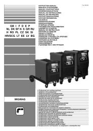
STANDARD ACCESSORIES 2- Power supply cable<br />
- Plasma cutting torch. 3- Compressed air connector (not present in the Kompressor version)<br />
- Connector kit for compressed air hookup. Connect the machine to a compressed air circuit with a minimum<br />
pressure of 5 bar and max.8 bar (TAB. 2).<br />
OPTIONAL ACCESSORIES 4- Pressure reduction valve for compressed air hookup (where<br />
- Spare electrode-nozzle kit. provided).<br />
- Electrode-nozzle extension kit (where provided for).<br />
Front panel (Fig. D1)<br />
3. TECHNICAL INFORMATION 1- Cutting current adjustment knob.<br />
DATA PLATE<br />
Used to set the cutting current intensity supplied by the machine, to<br />
The most important information regarding use and performance of the be chosen according to the application (material thickness / speed).<br />
plasma cutting system is summarised on the rating plate and has the See the TECHNICAL INFORMATION for the correct duty cyclefollowing<br />
meanings:<br />
pause to be chosen, depending on the selected current.<br />
Fig. A 2- Yellow LED indicating general alarm event:<br />
1- EUROPEAN standard of reference, for safety and construction of arc - When this comes on it indicates overheating of a component in the<br />
welding and plasma cutting machines.<br />
power circuit, or an incorrect input power supply voltage (over- or<br />
2- Symbol referring to the internal structure of the machine. under-voltage). Mains over- or under-voltage safeguard: stops the<br />
3- Symbol referring to plasma cutting procedure.<br />
machine: the power supply voltage is outside the +/- 15% range<br />
4- S symbol: indicates that cutting operations may be carried out in based on the rating plate value. WARNING: Exceeding the higher<br />
environments with heightened risk of electric shock (e.g. close to voltage limit given above will seriously damage the device.<br />
large metal masses).<br />
- During this event all machine operation will be disabled.<br />
5- Symbol indicating the main power supply:<br />
- Reset is automatic (the yellow LED goes off) when the values<br />
1~: single phase alternating voltage<br />
determining the above faults return within allowed limits.<br />
3~: 3-phase alternating voltage<br />
3- Yellow LED indicating that the torch is powered.<br />
6- Casing protection rating.<br />
- that the cutting circuit is enabled: Pilot<br />
When this is lit it indicates<br />
7- Technical specifications for main power supply:<br />
Arc or Cutting Arc "ON".<br />
- U : Alternating voltage and frequency of power supply to the - When it is off (cutting circuit OFF) the torch button is normally<br />
1<br />
machine (allowed limits ±10%):<br />
DISABLED (standby mode).<br />
- I : Maximum current absorbed by the line.<br />
- It is off, with the torch button enabled, under the following<br />
1 max<br />
- I : Effective current supplied<br />
conditions:<br />
1eff<br />
8- Performance of cutting circuit:<br />
- During the POST AIR phase.<br />
- If the pilot arc is not transferred to the piece within a maximum of<br />
- U 0 : maximum no-load voltage (open cutting circuit).<br />
2 seconds.<br />
- I 2/U 2 : Current and corresponding normalized voltage that the<br />
If the cutting arc is interrupted because the torch and piece are<br />
too far apart, if there is excessive electrode wear or if the torch is<br />
- X : the machine is able taken away from the piece by force.<br />
to supply the corresponding current (same column). It is<br />
- If a SAFEGUARD system has triggered.<br />
expressed in %, based on a 10 min. cycle (e.g. 60% = 6 4- Green LED indicating presence of mains power supply and that<br />
minutes work, 4 minutes pause; and so on).<br />
auxiliary circuits are powered.<br />
If the usage factors (on the plate, referring to a 40°C The control and service circuits are powered.<br />
environment) are exceeded the thermal cutout will trigger (the 5- Red LED indicating compressed air circuit (where present).<br />
machine will remain in standby until its temperature returns When this is lit it indicates overheating in the electric motor windings<br />
within the allowed limits).<br />
on the air compressor.<br />
- A/V-A/V: indicates the range over which the cutting current may be 6- Pressure gauge.<br />
adjusted (minimum - maximum) at the corresponding arc Used to read the air pressure.<br />
voltage. 7- Torch connection connector.<br />
9- Machine serial number (indispensable identification when asking for Torch with direct or centralised connection.<br />
technical assistance, ordering spare parts or discovering the origin of - The torch button is the only control device that can be used to<br />
the product).<br />
control the start and end of cutting operations.<br />
10- : Size of delayed action fuses to be provided to protect the - When the button is released the cycle is instantly interrupted at any<br />
power line.<br />
stage, while cooling air (post air) continues.<br />
11-Symbols referring to safety standards, the meaning of which is - Accidental operation: the cycle will only start if the button is<br />
explained in chapter 1 "General safety instructions for plasma arc pressed and kept down for a minimum of some tenths of a second.<br />
cutting”.<br />
- Electrical safeguard: button operation is disabled if the insulating<br />
machine is able to supply during cutting.<br />
Duty cycle: indicates the time for which<br />
nozzle holder has NOT been mounted on the head of the torch, or<br />
Note: The data plate shown here is an example for explaining the if it has been mounted incorrectly.<br />
meaning of the symbols and figures; the exact values of the technical 8- Earth cable connector<br />
specifications for your plasma cutting system must be read directly on the Front panel (Fig. D2)<br />
rating plate of the machine itself. 1- Cutting current adjustment knob.<br />
Used to set the cutting current intensity supplied by the machine, to<br />
OTHER TECHNICAL INFORMATION:<br />
be chosen according to the application (material thickness / speed).<br />
- POWER SOURCE: see table 1 (TAB.1) See the TECHNICAL INFORMATION for the correct duty cycle-<br />
- TORCH: see table 2 (TAB.2) pause to be chosen, depending on the selected current.<br />
The weight of the machine is given in table 1 (TAB. 1). 2- Red LED indicating general alarm event:<br />
- When this comes on it indicates overheating of a component in the<br />
4. DESCRIPTION OF THE PLASMA CUTTING SYSTEM power circuit, or an incorrect input power supply voltage (over- or<br />
The machine consists essentially of power modules built on PCB’s and under-voltage). Mains over- or under-voltage safeguard: stops the<br />
optimised for maximum reliability and minimum maintenance.<br />
machine: the power supply voltage is outside the +/- 15% range<br />
(Fig. B)<br />
based on the rating plate value. WARNING: Exceeding the higher<br />
1- Single phase power supply line, rectifier assembly and levelling voltage limit given above will seriously damage the device.<br />
capacitors.<br />
- During this event all machine operation will be disabled.<br />
2- Transistor (IGBT) switching bridge and drivers ; converts the rectified - Reset is automatic (the red LED goes off) when the values<br />
mains voltage into high frequency alternating voltage and adjusts the determining the above faults return within allowed limits.<br />
power according to the required cutting current/voltage. 3- Yellow LED indicating that the torch is powered.<br />
3- High frequency transformer: the primary winding is powered by the - When this is lit it indicates that the cutting circuit is enabled: Pilot<br />
voltage that has been converted by block 2; its function is to adapt Arc or Cutting Arc "ON".<br />
voltage and current to the values required for the cutting procedure - When it is off (cutting circuit OFF) the torch button is normally<br />
and at the same time to perform galvanic isolation of the cutting circuit DISABLED (standby mode).<br />
from the main power supply.<br />
- It is off, with the torch button enabled, under the following<br />
4- Secondary rectifier bridge with levelling inductance: converts the conditions:<br />
alternating voltage/current supplied by the secondary winding into - During the POST AIR phase.<br />
direct current/voltage with very low ripple.<br />
- If the pilot arc is not transferred to the piece within a maximum of<br />
5- Control and adjustment electronics: controls cutting current value 2 seconds.<br />
instantaneously and compares it with the operator’s setting;<br />
If the cutting arc is interrupted because the torch and piece are<br />
modulates IGBT driver control pulses that make the adjustment.<br />
too far apart, if there is excessive electrode wear or if the torch is<br />
Determines the dynamic current response during cutting and<br />
taken away from the piece by force.<br />
oversees the safety systems.<br />
- If a SAFEGUARD system has triggered.<br />
4- Green LED indicating presence of mains power supply and that<br />
CONTROL, ADJUSTMENT AND CONNECTION DEVICES<br />
auxiliary circuits are powered.<br />
Back panel (Fig. C)<br />
The control and service circuits are powered.<br />
1- Main switch 5- Yellow LED indicating phase failure (where provided).<br />
I (ON) Power source ready for operation, torch is not powered. Power When it comes on the yellow LED indicates a main supply phase<br />
source in standby<br />
failure, operation is disabled and reset is automatic 4 seconds after<br />
O (OFF) All functions off; auxiliary devices and indicator lights are all the fault has been corrected.<br />
- 5 -